US6249260B1 - T-top antenna for omni-directional horizontally-polarized operation - Google Patents
T-top antenna for omni-directional horizontally-polarized operationDownload PDFInfo
- Publication number
- US6249260B1 US6249260B1US09/356,073US35607399AUS6249260B1US 6249260 B1US6249260 B1US 6249260B1US 35607399 AUS35607399 AUS 35607399AUS 6249260 B1US6249260 B1US 6249260B1
- Authority
- US
- United States
- Prior art keywords
- outer edge
- dipole
- antenna
- antenna structure
- dipole antenna
- Prior art date
- Legal status (The legal status is an assumption and is not a legal conclusion. Google has not performed a legal analysis and makes no representation as to the accuracy of the status listed.)
- Expired - Fee Related
Links
- 230000005404monopoleEffects0.000claimsdescription14
- 239000002184metalSubstances0.000claimsdescription9
- 229910052751metalInorganic materials0.000claimsdescription9
- 230000000712assemblyEffects0.000claims1
- 238000000429assemblyMethods0.000claims1
- 230000005855radiationEffects0.000description19
- 239000004020conductorSubstances0.000description10
- 239000011152fibreglassSubstances0.000description7
- 239000003990capacitorSubstances0.000description6
- RYGMFSIKBFXOCR-UHFFFAOYSA-NCopperChemical compound[Cu]RYGMFSIKBFXOCR-UHFFFAOYSA-N0.000description4
- 239000011889copper foilSubstances0.000description4
- 238000010586diagramMethods0.000description4
- 239000000919ceramicSubstances0.000description3
- 230000001939inductive effectEffects0.000description3
- 238000003491arrayMethods0.000description1
- 238000005452bendingMethods0.000description1
- 230000008878couplingEffects0.000description1
- 238000010168coupling processMethods0.000description1
- 238000005859coupling reactionMethods0.000description1
- 230000000694effectsEffects0.000description1
- 239000006260foamSubstances0.000description1
- 239000000463materialSubstances0.000description1
- 230000004048modificationEffects0.000description1
- 238000012986modificationMethods0.000description1
Images

Classifications
- H—ELECTRICITY
- H01—ELECTRIC ELEMENTS
- H01Q—ANTENNAS, i.e. RADIO AERIALS
- H01Q1/00—Details of, or arrangements associated with, antennas
- H01Q1/36—Structural form of radiating elements, e.g. cone, spiral, umbrella; Particular materials used therewith
- H01Q1/38—Structural form of radiating elements, e.g. cone, spiral, umbrella; Particular materials used therewith formed by a conductive layer on an insulating support
- H—ELECTRICITY
- H01—ELECTRIC ELEMENTS
- H01Q—ANTENNAS, i.e. RADIO AERIALS
- H01Q9/00—Electrically-short antennas having dimensions not more than twice the operating wavelength and consisting of conductive active radiating elements
- H01Q9/04—Resonant antennas
- H01Q9/16—Resonant antennas with feed intermediate between the extremities of the antenna, e.g. centre-fed dipole
- H01Q9/28—Conical, cylindrical, cage, strip, gauze, or like elements having an extended radiating surface; Elements comprising two conical surfaces having collinear axes and adjacent apices and fed by two-conductor transmission lines
- H01Q9/285—Planar dipole
Definitions
- This inventionrelates to antennas of the T-Top type, particularly for achieving omni-directional horizontally-polarized operation.
- T-Top antennasBoth monopole and T-Top antennas have been used in aircraft for some time.
- T-Top antennasgenerate a radiation pattern of a natural elliptical shape and are limited in capacity for omni-directional horizontally-polarized operation.
- an antenna array in an elliptical T-Top sectionsits on a vertical blade support structure, and includes two bent dipole antenna elements which appear back to back on a printed circuit board with fully integrated micro-strip balun transformers.
- two very short director structures extending between opposite tips of opposite dipolesshape the radiation pattern and force it more circular from its more natural elliptical shape.
- a Wilkinson dividerdrives the baluns 180 degrees out of phase.
- a single connectorfeeds the Wilkinson divider.
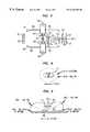
- FIG. 1is a partially schematic view of an antenna array, including a bottom view of a circuit board embodying the invention.
- FIG. 2is a top view of FIG. 1 .
- FIG. 3is a schematic diagram illustrating an antenna embodying the invention and including the array of FIGS. 1 and 2 and showing the connections to a feed allay.
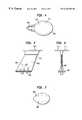
- FIG. 4is a top view of an antenna embodying the invention and including the array of FIGS. 1 to 3 .
- FIG. 5is side view of the antenna in FIG. 4 .
- FIG. 6is an elevation of the antenna in FIG. 5 .
- FIG. 7is a detailed view of the base of the antenna in FIGS. 4, 5 and 6 .
- FIG. 8is a diagram illustrating the T-Top radiation pattern in the azimuthal plane looking down on top of the elliptical disk in the T-Top of the antenna in FIGS. 4 to 7 .
- FIG. 9is a diagram of the radiation patterns in the elevational plane of the antenna in FIGS. 1 to 7 .
- an antenna array AA 1includes a circuit board CB 1 with a fiberglass board FB 1 supporting two copper-foil arrow-shaped back-to-back dipole antennas DA 1 and DA 2 .
- the dipole antenna DA 1includes two mutually-angular radiator elements RE 1 and RE 2 and the dipole antenna DA 2 includes two mutually-angular radiator elements RE 3 and RE 4 .
- the radiator elements RE 1 and RE 2 of the dipole antenna DA 1 and radiator elements RE 3 and RE 4 of the dipole antenna DA 2form respective arrowhead shapes directed away from each other.
- a gap GP 1separates the radiator elements RE 1 and RE 2 while a gap GP 2 separates the radiator elements RE 3 and RE 4 .
- a high-Q ceramic chip capacitor CA 1 between the elements RE 1 and RE 2tunes the dipole antenna DA 1
- a second high-Q ceramic chip capacitor CA 2 between the elements RC 3 and RE 4tunes the dipole antenna DA 2
- Mutually-separated conductive directors DI 1 and DI 2are spaced from, but span, the ends of the radiator elements RE 1 and RE 3
- mutually-separated conductive directors DI 3 and DI 4are spaced from, but span, the ends of radiator elements RE 2 and RE 4
- Central conductive copper foil stems (or legs) CS 1 and CS 2 and a copper foil cross member CM 1form an H-shaped structure with spaces SP 1 and SP 2 .
- the stem CS 1extends from radiator RE 1 to radiator RE 3 while the stem CS 1 extends between radiators RE 2 and RE 4 .
- the stems CS 1 and CS 2constitute inductive paths at the operating frequencies of the array AA 1 . Openings OP 1 and OP 2 in the metal at the cross member CM 1 allow passage of conductors through the metal and the fiberglass board FB 1 without contacting the metal of cross member CM 1 .
- FIG. 2shows the top view of the array in FIG. 1 .
- a gap GP 3isolates two copper-foil U-shaped conductors CO 1 and CO 2 located opposite the central stems CS 1 and CS 2 of the dipoles DA 1 and DA 2 .
- a resistor RE 1connects points PT 1 and PT 2 on the conductors CO 1 and CO 2 .
- the points PT 1 and PT 2are aligned with the centers of the openings OP 1 and OP 2 .
- the conductors CO 1 and CO 2form balun transformers BA 1 and BA 2 with the stems CS 1 and CS 2 .
- the conductors CO 1 and CO 2follow opposing clockwise and counterclockwise paths to produce 180 degree relative phase reversal during operation of the balun transformers BA 1 and BA 2 .
- Such phase reversalhelps generate an omni-directional radiation pattern.
- Tabs TA 1 and TA 2connect through the fiberglass board FB 1 to the ends of the respective radiator elements RE 1 and RE 2 of the dipole antenna DA 1 , and conductive tabs TA 3 and TA 4 , connected through the fiberglass board FB 1 to the ends of the radiation elements RE 3 and RE 4 of the dipole antenna DA 2 .
- the tabs TA 1 and TA 2help shape the radiation pattern and can be adjusted for tuning.
- Through holes HO 1 and HO 2 in the fiberglass boardallow passage of foam to lock the circuit board CB 1 in place.
- the alignment of the points PT 1 and PT 2 with the centers of openings OP 1 and OP 2allows conductors to pass through the openings and the fiberglass board FB 1 to connect to the points.
- FIG. 3is a schematic diagram illustrating the circuitry of the antenna array AA 1 in FIGS. 1 and 2.
- the resistor RE 1connects the balun transformers BT 1 and BT 2 between points PT 1 and PT 2 in FIG. 2 .
- the resistor RE 1is 100 ohms.
- Two quarter-wave 75-ohm coaxial cables CC 1 and CC 2have central conductors which connect to points PT 1 and PT 2 across the 100-ohm resistor RE 1 to form a Wilkinson divider that connects at one end to a single TNC(F) connector.
- the central conductors of the coaxial cables CC 1 and CC 2pass through the openings OP 1 and OP 2 as well as through the fiberglass board FB 1 , without touching the metal at the cross member CM 1 in FIGS. 1 and 2.
- the shields of the cables CC 1 and CC 2connect to the metal at the cross member CM 1 .
- the cables CC 1 and CC 2join to form a common shielded cable CC 3 .
- the stems CS 1 and CS 2form inductive connections from the radiator elements RE 1 to RE 4 to the central member CM 1 .
- the latterforms a ground plane which the outer shields of cables CC 1 and CC 2 connect to other grounds.
- the capacitors CA 1 and CA 2are ceramic chip capacitors connected across the balun transformers BT 1 and BT 2 .
- the spacings across the gaps GP 1 and GP 2have capacitive effects which add to the capacitances of the chip capacitors CA 1 and CA 2 .
- balun transformers BT 1 and BT 2are of the micro-strip type and are physically arranged on the printed circuit board to cause 180 degree relative phase reversal when driven by the Wilkinson divider.
- FIGS. 4, 5 and 6illustrate the support for the T-Top antenna array AA 1 of FIGS. 1 to 3 .
- an elliptical housing EH 1which surrounds the array AA 1 with the circuit board CB 1 as well as the resistor RE 1 , sits on top of a vertical blade VB 1 that supports the T-Top TT 1 .
- Suitable bolts BO 1support a base BA 1 of the blade VB 1 on a section of an aircraft as shown in FIGS. 5 and 7. According to other embodiments arrangements other than a base with bolts support the blade VB 1 .
- other forms of connectors and cable valuesserve in other embodiments.
- the long dimension of the circuit board CB 1extends along the longer axis of the eliptical housing EH 1 .
- the alignmentmy be otherwise in other embodiments.
- a vertical monopole VM 1passes vertically through the vertical blade at the front (left in FIG. 5) to furnish vertically polarized coverage along with regular vertically polarized transponder operation.
- the vertical monopole VM 1is of the wide-band type connected to a type N(F) connector to provide operation in two UHF frequency bands.
- the monopole VM 1may be any of several conventional types, for example a conventional folded type with an embedded quarter-wave stub for broadening the antenna's coverage to span the two frequency bands.
- the frequency bandsmay, for example, be 824-894 MHz and 1030-1090 MHz although other ranges are possible. Sufficient space separates the flexible coaxial feed cable (at the rear, to the right in FIG.
- FIG. 8illustrates a sample radiation pattern in the azimuthal plane (looking down on top of the elliptical disk), namely in the YAW plane. At 0 elevation, there is a gain of 0 dB i at a minimum.
- the E fieldextends horizontally. As shown in FIG.
- a nullappears directly above the T-Top and lobes appear on each side of the radiation pattern.
- a gain at 25 degrees above the metal frame of the aircraftis equal to +4 dB i maximum while a gain closer to zero is equal to 0 dB i minimum.
- the E fieldextends horizontally.
- the bottom of the circuit board CB 1faces downward in the T-Top TT 1 as shown in FIGS. 5 and 6. This allows easy access for the shields of the cables CC 1 and CC 2 to the cross member CM 1 which forms the ground plane of the circuit board CB 1 .
- the shields of the cable CC 1 and CC 2are grounded through the shield of the common cable CC 3 to the aircraft.
- the bending of the dipoles DA 1 and DA 2fill in nulls in front and back of the radiation pattern.
- the directors DI 1 and DI 2 as well as DI 3 and DI 4have approximate lengths ⁇ /4 where ⁇ is the operating wavelength at the center of the band and serve to reradiate energy and help produce a round radiation pattern.
- the directors DI 1 and DI 2 as well as DI 3 and DI 4are located at a fraction of ⁇ /4 from the radiators RA 1 , RA 2 , RA 3 , and RA 4 , close enough to operate in the near field.
- the radiators RA 1 , RA 2 , RA 3 , and RA 4are trimmed to help achieve the desired radiation pattern.
- the tabs TA 1 , TA 2 , TA 3 , and TA 4may also be trimmed to assist in producing a desired pattern.
- the disclosed embodimentsform circuit-board-mounted dipole antennas bent backwards toward each other and grounded at CM 1 through inductive legs (the stems CS 1 and CS 2 ).
- the latterform fully integrated, 180 degree out of phase, balun transformers with mutually-isolated U-shaped conductors CO 1 and CO 2 on the opposite side of the circuit board CB 1 .
- the conductors CO 1 and CO 2follow opposing paths to achieve the phase reversal when driven by a Wilkinson divider.
- the bent dipole antennas DA 1 and DA 2combine with the quarter wave directors DI 1 to DI 4 (which are very short and) disposed very close to the tips of the opposing dipoles at the near field of the dipole antennas, and with the tabs TA 1 to TA 4 as well as the capacitors CA 1 and CA 2 , to achieve omnidirectiolal radiation in a T-Top antenna.
- the tabs TA 1 to TA 4 and the directors DI 1 to DI 4are adjusted by removal of material to establish a desired omnidirectional radiation pattern.
- the configurationis repeated.
- a single CC 3feeds the array through the Wilkinson divider.
- FIGS. 1 to 3is used in supports that differ from the supports in FIGS. 4 to 7 , both with and without the vertical monopole.
Landscapes
- Details Of Aerials (AREA)
- Variable-Direction Aerials And Aerial Arrays (AREA)
Abstract
Description
This invention relates to antennas of the T-Top type, particularly for achieving omni-directional horizontally-polarized operation.
Both monopole and T-Top antennas have been used in aircraft for some time. T-Top antennas generate a radiation pattern of a natural elliptical shape and are limited in capacity for omni-directional horizontally-polarized operation.
According to an embodiment of the invention, an antenna array in an elliptical T-Top section sits on a vertical blade support structure, and includes two bent dipole antenna elements which appear back to back on a printed circuit board with fully integrated micro-strip balun transformers.
According to an embodiment two very short director structures extending between opposite tips of opposite dipoles shape the radiation pattern and force it more circular from its more natural elliptical shape.
According to another embodiment, a Wilkinson divider drives the baluns 180 degrees out of phase. A single connector feeds the Wilkinson divider.
The various features that characterize the invention are pointed out in the claims forming a part of this specification. The various advantages, benefits, and enhancements will become apparent with the following detailed description of exemplary embodiments when taken in view of the appended drawings.
FIG. 1 is a partially schematic view of an antenna array, including a bottom view of a circuit board embodying the invention.
FIG. 2 is a top view of FIG.1.
FIG. 3 is a schematic diagram illustrating an antenna embodying the invention and including the array of FIGS. 1 and 2 and showing the connections to a feed allay.
FIG. 4 is a top view of an antenna embodying the invention and including the array of FIGS. 1 to3.
FIG. 5 is side view of the antenna in FIG.4.
FIG. 6 is an elevation of the antenna in FIG.5.
FIG. 7 is a detailed view of the base of the antenna in FIGS. 4,5 and6.
FIG. 8 is a diagram illustrating the T-Top radiation pattern in the azimuthal plane looking down on top of the elliptical disk in the T-Top of the antenna in FIGS. 4 to7.
FIG. 9 is a diagram of the radiation patterns in the elevational plane of the antenna in FIGS. 1 to7.
In FIG. 1, an antenna array AA1 includes a circuit board CB1 with a fiberglass board FB1 supporting two copper-foil arrow-shaped back-to-back dipole antennas DA1 and DA2. The dipole antenna DA1 includes two mutually-angular radiator elements RE1 and RE2 and the dipole antenna DA2 includes two mutually-angular radiator elements RE3 and RE4. The radiator elements RE1 and RE2 of the dipole antenna DA1 and radiator elements RE3 and RE4 of the dipole antenna DA2 form respective arrowhead shapes directed away from each other. A gap GP1 separates the radiator elements RE1 and RE2 while a gap GP2 separates the radiator elements RE3 and RE4. A high-Q ceramic chip capacitor CA1 between the elements RE1 and RE2 tunes the dipole antenna DA1, and a second high-Q ceramic chip capacitor CA2 between the elements RC3 and RE4 tunes the dipole antenna DA2. Mutually-separated conductive directors DI1 and DI2 are spaced from, but span, the ends of the radiator elements RE1 and RE3, while mutually-separated conductive directors DI3 and DI4 are spaced from, but span, the ends of radiator elements RE2 and RE4. Central conductive copper foil stems (or legs) CS1 and CS2 and a copper foil cross member CM1 form an H-shaped structure with spaces SP1 and SP2. The stem CS1 extends from radiator RE1 to radiator RE3 while the stem CS1 extends between radiators RE2 and RE4. The stems CS1 and CS2 constitute inductive paths at the operating frequencies of the array AA1. Openings OP1 and OP2 in the metal at the cross member CM1 allow passage of conductors through the metal and the fiberglass board FB1 without contacting the metal of cross member CM1.
FIG. 2 shows the top view of the array in FIG.1. Here, a gap GP3 isolates two copper-foil U-shaped conductors CO1 and CO2 located opposite the central stems CS1 and CS2 of the dipoles DA1 and DA2. A resistor RE1 connects points PT1 and PT2 on the conductors CO1 and CO2. The points PT1 and PT2 are aligned with the centers of the openings OP1 and OP2. The conductors CO1 and CO2 form balun transformers BA1 and BA2 with the stems CS1 and CS2. The conductors CO1 and CO2 follow opposing clockwise and counterclockwise paths to produce 180 degree relative phase reversal during operation of the balun transformers BA1 and BA2. Such phase reversal helps generate an omni-directional radiation pattern. Tabs TA1 and TA2 connect through the fiberglass board FB1 to the ends of the respective radiator elements RE1 and RE2 of the dipole antenna DA1, and conductive tabs TA3 and TA4, connected through the fiberglass board FB1 to the ends of the radiation elements RE3 and RE4 of the dipole antenna DA2. The tabs TA1 and TA2 help shape the radiation pattern and can be adjusted for tuning. Through holes HO1 and HO2 in the fiberglass board allow passage of foam to lock the circuit board CB1 in place. The alignment of the points PT1 and PT2 with the centers of openings OP1 and OP2 allows conductors to pass through the openings and the fiberglass board FB1 to connect to the points.
FIG. 3 is a schematic diagram illustrating the circuitry of the antenna array AA1 in FIGS. 1 and 2. Here, the resistor RE1 connects the balun transformers BT1 and BT2 between points PT1 and PT2 in FIG.2. According to one embodiment of the invention the resistor RE1 is 100 ohms. However other values may be used and are contemplated. Two quarter-wave 75-ohm coaxial cables CC1 and CC2 have central conductors which connect to points PT1 and PT2 across the 100-ohm resistor RE1 to form a Wilkinson divider that connects at one end to a single TNC(F) connector. The central conductors of the coaxial cables CC1 and CC2 pass through the openings OP1 and OP2 as well as through the fiberglass board FB1, without touching the metal at the cross member CM1 in FIGS. 1 and 2. The shields of the cables CC1 and CC2 connect to the metal at the cross member CM1. The cables CC1 and CC2 join to form a common shielded cable CC3.
At the operating frequency of the system, the stems CS1 and CS2 form inductive connections from the radiator elements RE1 toRE 4 to the central member CM1. The latter forms a ground plane which the outer shields of cables CC1 and CC2 connect to other grounds. The capacitors CA1 and CA2 are ceramic chip capacitors connected across the balun transformers BT1 and BT2. The spacings across the gaps GP1 and GP2 have capacitive effects which add to the capacitances of the chip capacitors CA1 and CA2.
When both dipoles DA1 and DA2 transmit or receive radiation, no current flows through the 100-ohm resistor RE1. The directors DI1, DI2, and DI3, DI4 force the usual elliptical radiation pattern toward a more circular shape. Moreover, the dipole radiator elements in FIGS. 1 and 2 are angled inwardly to promote a more circular radiation pattern. The balun transformers BT1 and BT2 are of the micro-strip type and are physically arranged on the printed circuit board to cause 180 degree relative phase reversal when driven by the Wilkinson divider.
FIGS. 4,5 and6 illustrate the support for the T-Top antenna array AA1 of FIGS. 1 to3. Here, an elliptical housing EH1, which surrounds the array AA1 with the circuit board CB1 as well as the resistor RE1, sits on top of a vertical blade VB1 that supports the T-Top TT1. Suitable bolts BO1 support a base BA1 of the blade VB1 on a section of an aircraft as shown in FIGS. 5 and 7. According to other embodiments arrangements other than a base with bolts support the blade VB1. Also, other forms of connectors and cable values serve in other embodiments. According to the embodiment shown, the long dimension of the circuit board CB1 extends along the longer axis of the eliptical housing EH1. The alignment my be otherwise in other embodiments.
A vertical monopole VM1 passes vertically through the vertical blade at the front (left in FIG. 5) to furnish vertically polarized coverage along with regular vertically polarized transponder operation. The vertical monopole VM1 is of the wide-band type connected to a type N(F) connector to provide operation in two UHF frequency bands. The monopole VM1 may be any of several conventional types, for example a conventional folded type with an embedded quarter-wave stub for broadening the antenna's coverage to span the two frequency bands. The frequency bands may, for example, be 824-894 MHz and 1030-1090 MHz although other ranges are possible. Sufficient space separates the flexible coaxial feed cable (at the rear, to the right in FIG. 5) including the quarter-wave 75-ohm coaxial cables of the Wilkinson divider, and the TNC(F) cable from the vertical monopole VM1 to preserve the monopole's broad-band characteristics and minimize mutual coupling between the coaxial cables and the monopole. According to an embodiment
In operation of an embodiment shown, the array of FIGS. 1 to3 in a structure in FIGS. 4 to8, with the shields of the cables CA1 and CA2 connecting the ground plane at the metal of the member CM1 to the metal of the aircraft, produces a radiation pattern of the type illustrated in FIGS. 8 and 9. Specifically, FIG. 8 illustrates a sample radiation pattern in the azimuthal plane (looking down on top of the elliptical disk), namely in the YAW plane. At 0 elevation, there is a gain of 0 dBiat a minimum. The E field extends horizontally. As shown in FIG. 9, in the elevation plane looking from front to back or each side, namely the roll/pitch planes, a null appears directly above the T-Top and lobes appear on each side of the radiation pattern. As an example, a gain at 25 degrees above the metal frame of the aircraft is equal to +4 dBimaximum while a gain closer to zero is equal to 0 dBiminimum. The E field extends horizontally.
The bottom of the circuit board CB1 faces downward in the T-Top TT1 as shown in FIGS. 5 and 6. This allows easy access for the shields of the cables CC1 and CC2 to the cross member CM1 which forms the ground plane of the circuit board CB1. The shields of the cable CC1 and CC2 are grounded through the shield of the common cable CC3 to the aircraft.
The bending of the dipoles DA1 and DA2 fill in nulls in front and back of the radiation pattern. The directors DI1 and DI2 as well as DI3 and DI4 have approximate lengths λ/4 where λ is the operating wavelength at the center of the band and serve to reradiate energy and help produce a round radiation pattern. The directors DI1 and DI2 as well as DI3 and DI4 are located at a fraction of λ/4 from the radiators RA1, RA2, RA3, and RA4, close enough to operate in the near field. According to an embodiment the radiators RA1, RA2, RA3, and RA4 are trimmed to help achieve the desired radiation pattern. The tabs TA1, TA2, TA3, and TA4 may also be trimmed to assist in producing a desired pattern. Once a particular result is established, the particular structure is maintained in other arrays.
The disclosed embodiments form circuit-board-mounted dipole antennas bent backwards toward each other and grounded at CM1 through inductive legs (the stems CS1 and CS2). The latter form fully integrated, 180 degree out of phase, balun transformers with mutually-isolated U-shaped conductors CO1 and CO2 on the opposite side of the circuit board CB1. The conductors CO1 and CO2 follow opposing paths to achieve the phase reversal when driven by a Wilkinson divider. The bent dipole antennas DA1 and DA2 combine with the quarter wave directors DI1 to DI4 (which are very short and) disposed very close to the tips of the opposing dipoles at the near field of the dipole antennas, and with the tabs TA1 to TA4 as well as the capacitors CA1 and CA2, to achieve omnidirectiolal radiation in a T-Top antenna. According to embodiments of the invention, the tabs TA1 to TA4 and the directors DI1 to DI4 are adjusted by removal of material to establish a desired omnidirectional radiation pattern. According to an embodiment, once a particular configuration is established for a desired radiation pattern, the configuration is repeated. A single CC3 feeds the array through the Wilkinson divider.
While various embodiments have been described in detail, it will be understood that other and further modifications can be made to the herein disclosed embodiments without departing from the spirit and scope of the present invention. For example the 75 ohm cables are replaced by other values in other embodiments of the invention. Also, according to an embodiment, the array of FIGS. 1 to3 is used in supports that differ from the supports in FIGS. 4 to7, both with and without the vertical monopole.
Claims (26)
1. An antenna structure, comprising:
a dielectric board having two faces;
two bent dipole antennas placed back-to-back on one face of said dielectric board;
two balun transformers on the faces of said board each connected to one of said dipole antennas, and in 180 degree out-of-phase relationship with each other;
a first director assembly extending between said first dipole antenna and said second dipole antenna and a second director assembly extended between said first dipole antenna and said second dipole antenna.
2. A device as in claim1, wherein a Wilkinson divider is connected to said dipole antennas between said balun transformers.
3. An antenna structure as in claim2, wherein
a first of said dipole antennas includes a first outer edge at one end and a second outer edge at an opposing end;
a second of said dipole antennas includes a first outer edge at one end opposite a second outer edge at a second end;
and said first director assembly extends between said first outer edge of said fist dipole antenna and said first outer edge of said second dipole antenna,
and said second director assembly extends between said second outer edge of said first dipole antenna and said second outer edge of said second dipole antenna.
4. An antenna structure as in claim1, wherein said dipole antenna elements each include two dipole radiators elements and said first director assembly extends from a radiator element of said first dipole antenna to a first radiator of said second dipole antenna, and said second director assembly extends from a second radiator element of said first dipole antenna to a second radiator of said second dipole antenna.
5. An antenna structure as in claim1, wherein each of said director assemblies includes two directors.
6. An antenna structure as in claim1, wherein a resistor connects said balun transformers.
7. A device as in claim5, wherein a Wilkinson divider includes quarter-wave coaxial cables connects to each of the balun transformers.
8. An antenna structure as in claim7, wherein said coaxial cables of said Wilkinson divider join in a single third coaxial cable.
9. An antenna structure as in claim1, wherein a Wilkinson divider includes quarter-wave coaxial cables connects to each of the balun transformers.
10. An antenna structure as in claim1, wherein said balun transformers include two pairs of central sections, each pair connected one of said dipole antennas, each of said dipoles forming an arrowhead shape with one pair of said central sections.
11. An antenna structure as in claim10, wherein said central sections in each balun transformer include metal forming an H-shape with spaces at extremes, each of said dipole antennas including a pair of radiating elements; each of said central sections being formed on a face of said dielectric board and connected to said radiating elements.
12. An antenna structure as in claim11, wherein each of said balun transformers includes a U shaped element having conductive arms on the face of the dielectric board away from the central sections and located on face of the board opposite the central sections, said U-shaped elements being conductive and isolated from each other.
13. An antenna structure as in claim12, wherein said U shaped elements together form a clockwise and then counterclockwise path so as to form a modified S shape.
14. An antenna structure as in claim11, wherein said U-shaped elements are narrower in width than the central sections of said balun transformers.
15. An antenna structure as in claim10, wherein
a first of said dipole antennas includes a first outer edge at one end and a second outer end at an opposing end;
a second of said dipole antennas includes a first outer edge at one extremity opposite a second outer edge at a second extremity;
and said first director assembly extends between said first outer edge of said first dipole antenna and said first outer edge of said second dole antenna;
and said second director assembly extends between said second outer edge of said first dipole antenna and said second outer edge of said second dipole antenna.
16. An antenna structure as in claim1, wherein said board includes the dipole antennas on one face and two pairs of tabs on a second face, each pair of tabs being connected to a dipole antenna.
17. An antenna structure as in claim1, wherein
a first of said dipole antennas includes a first outer edge at one end and a second outer edge at an opposing end;
a second of said dipole antennas includes a first outer edge at one end opposite a second outer edge at a second end;
said first director assembly extends between said first outer edge of said first dipole antenna and said first outer edge of said second dipole antenna; and
said second director assembly extends between said second outer edge of said first dipole antenna and said second outer edge of said second dipole antenna.
18. An antenna structure, comprising:
a blade section extending, and a T-Top housing supported by said blade section;
said T-Top including:
a dielectric board having two faces;
two bent dipole antennas placed back-to-back on one face of said dielectric board;
two balun transformers on the faces of said board each connected to one of said dipole antennas, and in 180 out-of-phase relationship with each other;
a first director assembly extending between said first dipole and said second pole, and a second director assembly said first dipole and said second pole.
19. An antenna structure as in claim18, wherein said blade section includes a wide-band monopole.
20. An antenna structure as in claim19, wherein said monopole is tuned to two frequency bands.
21. An antenna structure as in claim20, wherein said monopole includes a quarter-wave stub.
22. An antenna structure as in claim21, wherein said blade section includes a monopole, said monopole and said coaxial cable being placed for maximum decoupling between each other.
23. An antenna structure as in claim19, wherein said monopole is of the folded type.
24. An antenna structure as in claim18, wherein said dipole antennas are connected to a coaxial cable.
25. An antenna structure as in claim24, wherein said coaxial cable includes a Wilkinson divider.
26. An antenna structure as in claim18, wherein
a first of said dipole antennas includes a first outer edge at one end and a second outer edge at an opposing end;
a second of said dipole antennas includes a first outer edge at one end opposite a second outer edge at a second end;
and said first director assembly extends between said first outer edge of said first dipole antenna and said first outer edge of said second dipole antenna;
and said second director assembly extends between said second outer edge of said first dipole antenna and said second outer edge of said second dipole antenna.
Priority Applications (1)
| Application Number | Priority Date | Filing Date | Title |
|---|---|---|---|
| US09/356,073US6249260B1 (en) | 1999-07-16 | 1999-07-16 | T-top antenna for omni-directional horizontally-polarized operation |
Applications Claiming Priority (1)
| Application Number | Priority Date | Filing Date | Title |
|---|---|---|---|
| US09/356,073US6249260B1 (en) | 1999-07-16 | 1999-07-16 | T-top antenna for omni-directional horizontally-polarized operation |
Publications (1)
| Publication Number | Publication Date |
|---|---|
| US6249260B1true US6249260B1 (en) | 2001-06-19 |
Family
ID=23400006
Family Applications (1)
| Application Number | Title | Priority Date | Filing Date |
|---|---|---|---|
| US09/356,073Expired - Fee RelatedUS6249260B1 (en) | 1999-07-16 | 1999-07-16 | T-top antenna for omni-directional horizontally-polarized operation |
Country Status (1)
| Country | Link |
|---|---|
| US (1) | US6249260B1 (en) |
Cited By (20)
| Publication number | Priority date | Publication date | Assignee | Title |
|---|---|---|---|---|
| US20020126057A1 (en)* | 2000-07-18 | 2002-09-12 | King Patrick F. | Wireless communication device and method |
| US20020175818A1 (en)* | 2000-07-18 | 2002-11-28 | King Patrick F. | Wireless communication device and method for discs |
| US20020175873A1 (en)* | 2000-07-18 | 2002-11-28 | King Patrick F. | Grounded antenna for a wireless communication device and method |
| US20040036655A1 (en)* | 2002-08-22 | 2004-02-26 | Robert Sainati | Multi-layer antenna structure |
| US20040252070A1 (en)* | 2003-06-12 | 2004-12-16 | Huey-Ru Chuang | Printed dual dipole antenna |
| US20050040994A1 (en)* | 2003-08-22 | 2005-02-24 | Checkpoint Systems, Inc. | Security tag with three dimensional antenna array made from flat stock |
| US20050116874A1 (en)* | 2003-12-02 | 2005-06-02 | Ahmed El-Mahdawy | Horizontally polarized omni-directional antenna |
| US20050116869A1 (en)* | 2003-10-28 | 2005-06-02 | Siegler Michael J. | Multi-band antenna structure |
| US20050212674A1 (en)* | 2004-03-29 | 2005-09-29 | Impinj, Inc., A Delaware Corporation | RFID tag uncoupling one of its antenna ports and methods |
| US20060055620A1 (en)* | 2004-03-29 | 2006-03-16 | Impinj, Inc. | Circuits for RFID tags with multiple non-independently driven RF ports |
| US7191507B2 (en) | 2002-04-24 | 2007-03-20 | Mineral Lassen Llc | Method of producing a wireless communication device |
| US20090045966A1 (en)* | 2007-07-20 | 2009-02-19 | Marko Rocznik | Clothing means having a sensor element for detecting a left position |
| USD587691S1 (en) | 2004-03-29 | 2009-03-03 | Impinj, Inc. | Radio frequency identification tag antenna assembly |
| US7525438B2 (en) | 2004-03-31 | 2009-04-28 | Impinj, Inc. | RFID tags combining signals received from multiple RF ports |
| US7616120B1 (en) | 2007-02-28 | 2009-11-10 | Impinj, Inc. | Multiple RF-port modulator for RFID tag |
| US8059049B2 (en)* | 2006-10-11 | 2011-11-15 | Raytheon Company | Dual band active array antenna |
| JPWO2014122925A1 (en)* | 2013-02-05 | 2017-01-26 | パナソニックIpマネジメント株式会社 | Antenna device |
| US10431881B2 (en)* | 2016-04-29 | 2019-10-01 | Pegatron Corporation | Electronic apparatus and dual band printed antenna of the same |
| US10535917B1 (en) | 2018-05-03 | 2020-01-14 | First Rf Corporation | Antenna structure for use with a horizontally polarized signal |
| US11509039B2 (en)* | 2017-12-26 | 2022-11-22 | Samsung Electro-Mechanics Co., Ltd. | Antenna module and antenna apparatus |
Citations (38)
| Publication number | Priority date | Publication date | Assignee | Title |
|---|---|---|---|---|
| US2700104A (en) | 1949-04-29 | 1955-01-18 | Airborne Instr Lab Inc | Antenna feed system |
| US2968038A (en) | 1959-02-19 | 1961-01-10 | Hauptschein Arthur | Multiband tail-cap antenna |
| US3604006A (en) | 1968-12-11 | 1971-09-07 | William C Rogers | Aircraft mounted mast for multiple antennae |
| US3739390A (en) | 1970-12-14 | 1973-06-12 | Beukers Labor Inc | Duplexed antenna for retransmission devices |
| US3945013A (en) | 1973-10-31 | 1976-03-16 | Siemens Aktiengesellschaft | Double omni-directional antenna |
| US4008479A (en) | 1975-11-03 | 1977-02-15 | Chu Associates, Inc. | Dual-frequency circularly polarized spiral antenna for satellite navigation |
| US4072952A (en) | 1976-10-04 | 1978-02-07 | The United States Of America As Represented By The Secretary Of The Army | Microwave landing system antenna |
| US4083050A (en) | 1976-09-01 | 1978-04-04 | The Bendix Corporation | Dual band monopole omni antenna |
| US4084162A (en) | 1975-05-15 | 1978-04-11 | Etat Francais Represented By Delegation Ministerielle Pour L'armement | Folded back doublet microstrip antenna |
| US4160977A (en) | 1978-02-23 | 1979-07-10 | Davis Ross A | Automobile antenna |
| US4329690A (en) | 1978-11-13 | 1982-05-11 | International Telephone And Telegraph Corporation | Multiple shipboard antenna configuration |
| US4331961A (en) | 1980-04-08 | 1982-05-25 | Davis Ross A | Windshield antenna |
| US4392139A (en) | 1979-12-14 | 1983-07-05 | The Boeing Company | Aircraft television antenna receiving system |
| US4438437A (en) | 1981-09-14 | 1984-03-20 | Hazeltine Corporation | Dual mode blade antenna |
| US4573056A (en)* | 1981-12-18 | 1986-02-25 | Thomson Csf | Dipole radiator excited by a shielded slot line |
| US4635066A (en) | 1984-03-08 | 1987-01-06 | Avionics Antenna Systems | Multiband multimode aircraft antenna |
| US4686536A (en)* | 1985-08-15 | 1987-08-11 | Canadian Marconi Company | Crossed-drooping dipole antenna |
| US4825220A (en) | 1986-11-26 | 1989-04-25 | General Electric Company | Microstrip fed printed dipole with an integral balun |
| US4847626A (en)* | 1987-07-01 | 1989-07-11 | Motorola, Inc. | Microstrip balun-antenna |
| US4868577A (en) | 1987-12-23 | 1989-09-19 | Wingard Jefferson C | Multiband television/communications antenna |
| US4870426A (en) | 1988-08-22 | 1989-09-26 | The Boeing Company | Dual band antenna element |
| US5021799A (en) | 1989-07-03 | 1991-06-04 | Motorola, Inc. | High permitivity dielectric microstrip dipole antenna |
| US5148183A (en) | 1990-06-01 | 1992-09-15 | Algira Primo Inc. | Four-way antenna |
| US5191352A (en) | 1990-08-02 | 1993-03-02 | Navstar Limited | Radio frequency apparatus |
| US5198826A (en) | 1989-09-22 | 1993-03-30 | Nippon Sheet Glass Co., Ltd. | Wide-band loop antenna with outer and inner loop conductors |
| US5272485A (en) | 1992-02-04 | 1993-12-21 | Trimble Navigation Limited | Microstrip antenna with integral low-noise amplifier for use in global positioning system (GPS) receivers |
| US5300936A (en) | 1992-09-30 | 1994-04-05 | Loral Aerospace Corp. | Multiple band antenna |
| US5313218A (en) | 1990-09-06 | 1994-05-17 | Ncr Corporation | Antenna assembly |
| US5489912A (en) | 1994-09-08 | 1996-02-06 | Comant Industries, Inc. | Non-resonant antenna and feed apparatus therefor |
| US5495260A (en) | 1993-08-09 | 1996-02-27 | Motorola, Inc. | Printed circuit dipole antenna |
| US5532708A (en) | 1995-03-03 | 1996-07-02 | Motorola, Inc. | Single compact dual mode antenna |
| US5572226A (en) | 1992-05-15 | 1996-11-05 | Micron Technology, Inc. | Spherical antenna pattern(s) from antenna(s) arranged in a two-dimensional plane for use in RFID tags and labels |
| US5610620A (en) | 1995-05-19 | 1997-03-11 | Comant Industries, Inc. | Combination antenna |
| US5614917A (en) | 1993-10-04 | 1997-03-25 | Ford Motor Company | RF sail pumped tuned antenna |
| US5621420A (en) | 1995-04-07 | 1997-04-15 | Comant Industries, Inc. | Duplex monopole antenna |
| US5838285A (en)* | 1995-12-05 | 1998-11-17 | Motorola, Inc. | Wide beamwidth antenna system and method for making the same |
| US5892486A (en)* | 1996-10-11 | 1999-04-06 | Channel Master Llc | Broad band dipole element and array |
| US5999141A (en)* | 1997-06-02 | 1999-12-07 | Weldon; Thomas Paul | Enclosed dipole antenna and feeder system |
- 1999
- 1999-07-16USUS09/356,073patent/US6249260B1/ennot_activeExpired - Fee Related
Patent Citations (38)
| Publication number | Priority date | Publication date | Assignee | Title |
|---|---|---|---|---|
| US2700104A (en) | 1949-04-29 | 1955-01-18 | Airborne Instr Lab Inc | Antenna feed system |
| US2968038A (en) | 1959-02-19 | 1961-01-10 | Hauptschein Arthur | Multiband tail-cap antenna |
| US3604006A (en) | 1968-12-11 | 1971-09-07 | William C Rogers | Aircraft mounted mast for multiple antennae |
| US3739390A (en) | 1970-12-14 | 1973-06-12 | Beukers Labor Inc | Duplexed antenna for retransmission devices |
| US3945013A (en) | 1973-10-31 | 1976-03-16 | Siemens Aktiengesellschaft | Double omni-directional antenna |
| US4084162A (en) | 1975-05-15 | 1978-04-11 | Etat Francais Represented By Delegation Ministerielle Pour L'armement | Folded back doublet microstrip antenna |
| US4008479A (en) | 1975-11-03 | 1977-02-15 | Chu Associates, Inc. | Dual-frequency circularly polarized spiral antenna for satellite navigation |
| US4083050A (en) | 1976-09-01 | 1978-04-04 | The Bendix Corporation | Dual band monopole omni antenna |
| US4072952A (en) | 1976-10-04 | 1978-02-07 | The United States Of America As Represented By The Secretary Of The Army | Microwave landing system antenna |
| US4160977A (en) | 1978-02-23 | 1979-07-10 | Davis Ross A | Automobile antenna |
| US4329690A (en) | 1978-11-13 | 1982-05-11 | International Telephone And Telegraph Corporation | Multiple shipboard antenna configuration |
| US4392139A (en) | 1979-12-14 | 1983-07-05 | The Boeing Company | Aircraft television antenna receiving system |
| US4331961A (en) | 1980-04-08 | 1982-05-25 | Davis Ross A | Windshield antenna |
| US4438437A (en) | 1981-09-14 | 1984-03-20 | Hazeltine Corporation | Dual mode blade antenna |
| US4573056A (en)* | 1981-12-18 | 1986-02-25 | Thomson Csf | Dipole radiator excited by a shielded slot line |
| US4635066A (en) | 1984-03-08 | 1987-01-06 | Avionics Antenna Systems | Multiband multimode aircraft antenna |
| US4686536A (en)* | 1985-08-15 | 1987-08-11 | Canadian Marconi Company | Crossed-drooping dipole antenna |
| US4825220A (en) | 1986-11-26 | 1989-04-25 | General Electric Company | Microstrip fed printed dipole with an integral balun |
| US4847626A (en)* | 1987-07-01 | 1989-07-11 | Motorola, Inc. | Microstrip balun-antenna |
| US4868577A (en) | 1987-12-23 | 1989-09-19 | Wingard Jefferson C | Multiband television/communications antenna |
| US4870426A (en) | 1988-08-22 | 1989-09-26 | The Boeing Company | Dual band antenna element |
| US5021799A (en) | 1989-07-03 | 1991-06-04 | Motorola, Inc. | High permitivity dielectric microstrip dipole antenna |
| US5198826A (en) | 1989-09-22 | 1993-03-30 | Nippon Sheet Glass Co., Ltd. | Wide-band loop antenna with outer and inner loop conductors |
| US5148183A (en) | 1990-06-01 | 1992-09-15 | Algira Primo Inc. | Four-way antenna |
| US5191352A (en) | 1990-08-02 | 1993-03-02 | Navstar Limited | Radio frequency apparatus |
| US5313218A (en) | 1990-09-06 | 1994-05-17 | Ncr Corporation | Antenna assembly |
| US5272485A (en) | 1992-02-04 | 1993-12-21 | Trimble Navigation Limited | Microstrip antenna with integral low-noise amplifier for use in global positioning system (GPS) receivers |
| US5572226A (en) | 1992-05-15 | 1996-11-05 | Micron Technology, Inc. | Spherical antenna pattern(s) from antenna(s) arranged in a two-dimensional plane for use in RFID tags and labels |
| US5300936A (en) | 1992-09-30 | 1994-04-05 | Loral Aerospace Corp. | Multiple band antenna |
| US5495260A (en) | 1993-08-09 | 1996-02-27 | Motorola, Inc. | Printed circuit dipole antenna |
| US5614917A (en) | 1993-10-04 | 1997-03-25 | Ford Motor Company | RF sail pumped tuned antenna |
| US5489912A (en) | 1994-09-08 | 1996-02-06 | Comant Industries, Inc. | Non-resonant antenna and feed apparatus therefor |
| US5532708A (en) | 1995-03-03 | 1996-07-02 | Motorola, Inc. | Single compact dual mode antenna |
| US5621420A (en) | 1995-04-07 | 1997-04-15 | Comant Industries, Inc. | Duplex monopole antenna |
| US5610620A (en) | 1995-05-19 | 1997-03-11 | Comant Industries, Inc. | Combination antenna |
| US5838285A (en)* | 1995-12-05 | 1998-11-17 | Motorola, Inc. | Wide beamwidth antenna system and method for making the same |
| US5892486A (en)* | 1996-10-11 | 1999-04-06 | Channel Master Llc | Broad band dipole element and array |
| US5999141A (en)* | 1997-06-02 | 1999-12-07 | Weldon; Thomas Paul | Enclosed dipole antenna and feeder system |
Cited By (51)
| Publication number | Priority date | Publication date | Assignee | Title |
|---|---|---|---|---|
| US7397438B2 (en) | 2000-07-18 | 2008-07-08 | Mineral Lassen Llc | Wireless communication device and method |
| US7098850B2 (en) | 2000-07-18 | 2006-08-29 | King Patrick F | Grounded antenna for a wireless communication device and method |
| US20020175818A1 (en)* | 2000-07-18 | 2002-11-28 | King Patrick F. | Wireless communication device and method for discs |
| US20020175873A1 (en)* | 2000-07-18 | 2002-11-28 | King Patrick F. | Grounded antenna for a wireless communication device and method |
| US20020126057A1 (en)* | 2000-07-18 | 2002-09-12 | King Patrick F. | Wireless communication device and method |
| US6806842B2 (en) | 2000-07-18 | 2004-10-19 | Marconi Intellectual Property (Us) Inc. | Wireless communication device and method for discs |
| US6828941B2 (en) | 2000-07-18 | 2004-12-07 | Marconi Intellectual Property (Us) Inc. | Wireless communication device and method |
| US7411552B2 (en) | 2000-07-18 | 2008-08-12 | Mineral Lassen Llc | Grounded antenna for a wireless communication device and method |
| US7460078B2 (en) | 2000-07-18 | 2008-12-02 | Mineral Lassen Llc | Wireless communication device and method |
| USRE43683E1 (en) | 2000-07-18 | 2012-09-25 | Mineral Lassen Llc | Wireless communication device and method for discs |
| US6483473B1 (en)* | 2000-07-18 | 2002-11-19 | Marconi Communications Inc. | Wireless communication device and method |
| US20050190111A1 (en)* | 2000-07-18 | 2005-09-01 | King Patrick F. | Wireless communication device and method |
| US20070171139A1 (en)* | 2000-07-18 | 2007-07-26 | Mineral Lassen Llc | Grounded antenna for a wireless communication device and method |
| US20050275591A1 (en)* | 2000-07-18 | 2005-12-15 | Mineral Lassen Llc | Grounded antenna for a wireless communication device and method |
| US7193563B2 (en) | 2000-07-18 | 2007-03-20 | King Patrick F | Grounded antenna for a wireless communication device and method |
| US20070001916A1 (en)* | 2000-07-18 | 2007-01-04 | Mineral Lassen Llc | Wireless communication device and method |
| US20100095519A1 (en)* | 2002-04-24 | 2010-04-22 | Forster Ian J | Apparatus for manufacturing wireless communication device |
| US7546675B2 (en) | 2002-04-24 | 2009-06-16 | Ian J Forster | Method and system for manufacturing a wireless communication device |
| US7647691B2 (en) | 2002-04-24 | 2010-01-19 | Ian J Forster | Method of producing antenna elements for a wireless communication device |
| US20080168647A1 (en)* | 2002-04-24 | 2008-07-17 | Forster Ian J | Manufacturing method for a wireless communication device and manufacturing apparatus |
| US8136223B2 (en) | 2002-04-24 | 2012-03-20 | Mineral Lassen Llc | Apparatus for forming a wireless communication device |
| US20100089891A1 (en)* | 2002-04-24 | 2010-04-15 | Forster Ian J | Method of preparing an antenna |
| US7191507B2 (en) | 2002-04-24 | 2007-03-20 | Mineral Lassen Llc | Method of producing a wireless communication device |
| US8171624B2 (en) | 2002-04-24 | 2012-05-08 | Mineral Lassen Llc | Method and system for preparing wireless communication chips for later processing |
| US7730606B2 (en) | 2002-04-24 | 2010-06-08 | Ian J Forster | Manufacturing method for a wireless communication device and manufacturing apparatus |
| US7908738B2 (en) | 2002-04-24 | 2011-03-22 | Mineral Lassen Llc | Apparatus for manufacturing a wireless communication device |
| US7650683B2 (en) | 2002-04-24 | 2010-01-26 | Forster Ian J | Method of preparing an antenna |
| US8302289B2 (en) | 2002-04-24 | 2012-11-06 | Mineral Lassen Llc | Apparatus for preparing an antenna for use with a wireless communication device |
| US20040036655A1 (en)* | 2002-08-22 | 2004-02-26 | Robert Sainati | Multi-layer antenna structure |
| US7042412B2 (en)* | 2003-06-12 | 2006-05-09 | Mediatek Incorporation | Printed dual dipole antenna |
| US20040252070A1 (en)* | 2003-06-12 | 2004-12-16 | Huey-Ru Chuang | Printed dual dipole antenna |
| US20050040994A1 (en)* | 2003-08-22 | 2005-02-24 | Checkpoint Systems, Inc. | Security tag with three dimensional antenna array made from flat stock |
| US7042413B2 (en)* | 2003-08-22 | 2006-05-09 | Checkpoint Systems, Inc. | Security tag with three dimensional antenna array made from flat stock |
| US20050116869A1 (en)* | 2003-10-28 | 2005-06-02 | Siegler Michael J. | Multi-band antenna structure |
| US7088299B2 (en) | 2003-10-28 | 2006-08-08 | Dsp Group Inc. | Multi-band antenna structure |
| US20050116874A1 (en)* | 2003-12-02 | 2005-06-02 | Ahmed El-Mahdawy | Horizontally polarized omni-directional antenna |
| US7006051B2 (en)* | 2003-12-02 | 2006-02-28 | Frc Components Products Inc. | Horizontally polarized omni-directional antenna |
| US20050212674A1 (en)* | 2004-03-29 | 2005-09-29 | Impinj, Inc., A Delaware Corporation | RFID tag uncoupling one of its antenna ports and methods |
| US7667589B2 (en) | 2004-03-29 | 2010-02-23 | Impinj, Inc. | RFID tag uncoupling one of its antenna ports and methods |
| US7528728B2 (en) | 2004-03-29 | 2009-05-05 | Impinj Inc. | Circuits for RFID tags with multiple non-independently driven RF ports |
| USD587691S1 (en) | 2004-03-29 | 2009-03-03 | Impinj, Inc. | Radio frequency identification tag antenna assembly |
| US20060055620A1 (en)* | 2004-03-29 | 2006-03-16 | Impinj, Inc. | Circuits for RFID tags with multiple non-independently driven RF ports |
| US7525438B2 (en) | 2004-03-31 | 2009-04-28 | Impinj, Inc. | RFID tags combining signals received from multiple RF ports |
| US8059049B2 (en)* | 2006-10-11 | 2011-11-15 | Raytheon Company | Dual band active array antenna |
| US7616120B1 (en) | 2007-02-28 | 2009-11-10 | Impinj, Inc. | Multiple RF-port modulator for RFID tag |
| US8294582B1 (en) | 2007-02-28 | 2012-10-23 | Impinj, Inc. | Multiple RF-port modulator for RFID tag |
| US20090045966A1 (en)* | 2007-07-20 | 2009-02-19 | Marko Rocznik | Clothing means having a sensor element for detecting a left position |
| JPWO2014122925A1 (en)* | 2013-02-05 | 2017-01-26 | パナソニックIpマネジメント株式会社 | Antenna device |
| US10431881B2 (en)* | 2016-04-29 | 2019-10-01 | Pegatron Corporation | Electronic apparatus and dual band printed antenna of the same |
| US11509039B2 (en)* | 2017-12-26 | 2022-11-22 | Samsung Electro-Mechanics Co., Ltd. | Antenna module and antenna apparatus |
| US10535917B1 (en) | 2018-05-03 | 2020-01-14 | First Rf Corporation | Antenna structure for use with a horizontally polarized signal |
Similar Documents
| Publication | Publication Date | Title |
|---|---|---|
| US6249260B1 (en) | T-top antenna for omni-directional horizontally-polarized operation | |
| US6734828B2 (en) | Dual band planar high-frequency antenna | |
| US10892559B2 (en) | Dipole antenna | |
| EP1590857B1 (en) | Low profile dual frequency dipole antenna structure | |
| EP1376757B1 (en) | Dual-band directional/omnidirectional antenna | |
| EP0777295B1 (en) | Antenna device having two resonance frequencies | |
| US5003318A (en) | Dual frequency microstrip patch antenna with capacitively coupled feed pins | |
| US6639558B2 (en) | Multi frequency stacked patch antenna with improved frequency band isolation | |
| EP1466386B1 (en) | Enhanced bandwidth dual layer current sheet antenna | |
| US4860020A (en) | Compact, wideband antenna system | |
| US4575725A (en) | Double tuned, coupled microstrip antenna | |
| US20050253769A1 (en) | Crossed dipole antenna element | |
| US11799207B2 (en) | Antennas for reception of satellite signals | |
| US20060001574A1 (en) | Wideband Patch Antenna | |
| US5940037A (en) | Stacked patch antenna with frequency band isolation | |
| US7151505B2 (en) | Quadrifilar helix antenna | |
| US5818397A (en) | Circularly polarized horizontal beamwidth antenna having binary feed network with microstrip transmission line | |
| JPS62285502A (en) | Wide band microstrip antenna | |
| US7339543B2 (en) | Array antenna with low profile | |
| US6977613B2 (en) | High performance dual-patch antenna with fast impedance matching holes | |
| US4740793A (en) | Antenna elements and arrays | |
| US4485385A (en) | Broadband diamond-shaped antenna | |
| KR100198687B1 (en) | Array antenna with forced excitation | |
| US3488657A (en) | Low profile antenna | |
| US5103238A (en) | Twisted Z omnidirectional antenna |
Legal Events
| Date | Code | Title | Description |
|---|---|---|---|
| AS | Assignment | Owner name:COMANT INDUSTRIES, INC., CALIFORNIA Free format text:ASSIGNMENT OF ASSIGNORS INTEREST;ASSIGNOR:HOLLOWAY, DAVID J.;REEL/FRAME:010454/0780 Effective date:19990902 | |
| CC | Certificate of correction | ||
| REMI | Maintenance fee reminder mailed | ||
| FPAY | Fee payment | Year of fee payment:4 | |
| SULP | Surcharge for late payment | ||
| REMI | Maintenance fee reminder mailed | ||
| REIN | Reinstatement after maintenance fee payment confirmed | ||
| FP | Lapsed due to failure to pay maintenance fee | Effective date:20090619 | |
| FEPP | Fee payment procedure | Free format text:PETITION RELATED TO MAINTENANCE FEES FILED (ORIGINAL EVENT CODE: PMFP); ENTITY STATUS OF PATENT OWNER: LARGE ENTITY Free format text:PETITION RELATED TO MAINTENANCE FEES GRANTED (ORIGINAL EVENT CODE: PMFG); ENTITY STATUS OF PATENT OWNER: LARGE ENTITY | |
| PRDP | Patent reinstated due to the acceptance of a late maintenance fee | Effective date:20101102 | |
| FPAY | Fee payment | Year of fee payment:8 | |
| SULP | Surcharge for late payment | ||
| REMI | Maintenance fee reminder mailed | ||
| LAPS | Lapse for failure to pay maintenance fees | ||
| STCH | Information on status: patent discontinuation | Free format text:PATENT EXPIRED DUE TO NONPAYMENT OF MAINTENANCE FEES UNDER 37 CFR 1.362 | |
| FP | Lapsed due to failure to pay maintenance fee | Effective date:20130619 |