US6246677B1 - Automatic meter reading data communication system - Google Patents
Automatic meter reading data communication systemDownload PDFInfo
- Publication number
- US6246677B1 US6246677B1US09/242,793US24279399AUS6246677B1US 6246677 B1US6246677 B1US 6246677B1US 24279399 AUS24279399 AUS 24279399AUS 6246677 B1US6246677 B1US 6246677B1
- Authority
- US
- United States
- Prior art keywords
- management unit
- interface management
- data
- commodity
- meter
- Prior art date
- Legal status (The legal status is an assumption and is not a legal conclusion. Google has not performed a legal analysis and makes no representation as to the accuracy of the status listed.)
- Expired - Lifetime
Links
- 230000006854communicationEffects0.000titleclaimsabstractdescription161
- 238000004891communicationMethods0.000titleclaimsabstractdescription160
- 238000001228spectrumMethods0.000claimsabstractdescription64
- 230000006870functionEffects0.000claimsdescription21
- 238000000034methodMethods0.000claimsdescription21
- 230000000977initiatory effectEffects0.000claimsdescription4
- 238000012545processingMethods0.000claimsdescription2
- 238000013480data collectionMethods0.000abstract1
- 238000007726management methodMethods0.000description182
- 238000010586diagramMethods0.000description27
- 239000004020conductorSubstances0.000description17
- 230000004044responseEffects0.000description17
- XLYOFNOQVPJJNP-UHFFFAOYSA-NwaterSubstancesOXLYOFNOQVPJJNP-UHFFFAOYSA-N0.000description13
- 230000005540biological transmissionEffects0.000description12
- 230000008859changeEffects0.000description8
- 238000012360testing methodMethods0.000description6
- 238000013497data interchangeMethods0.000description5
- 230000000694effectsEffects0.000description5
- 238000009434installationMethods0.000description5
- 230000001413cellular effectEffects0.000description4
- 230000009977dual effectEffects0.000description4
- 230000010355oscillationEffects0.000description4
- 230000000007visual effectEffects0.000description4
- 239000013078crystalSubstances0.000description3
- 238000001514detection methodMethods0.000description3
- 239000004973liquid crystal related substanceSubstances0.000description3
- 230000008569processEffects0.000description3
- 230000007480spreadingEffects0.000description3
- 230000004397blinkingEffects0.000description2
- 230000000295complement effectEffects0.000description2
- 238000013461designMethods0.000description2
- 238000004519manufacturing processMethods0.000description2
- 238000012544monitoring processMethods0.000description2
- 230000002269spontaneous effectEffects0.000description2
- UGFAIRIUMAVXCW-UHFFFAOYSA-NCarbon monoxideChemical compound[O+]#[C-]UGFAIRIUMAVXCW-UHFFFAOYSA-N0.000description1
- 230000004913activationEffects0.000description1
- 230000003466anti-cipated effectEffects0.000description1
- 230000009118appropriate responseEffects0.000description1
- 230000006399behaviorEffects0.000description1
- 230000008901benefitEffects0.000description1
- 230000015572biosynthetic processEffects0.000description1
- 229910002091carbon monoxideInorganic materials0.000description1
- 238000012790confirmationMethods0.000description1
- 238000010276constructionMethods0.000description1
- 238000002592echocardiographyMethods0.000description1
- 238000005516engineering processMethods0.000description1
- 230000007613environmental effectEffects0.000description1
- 239000000835fiberSubstances0.000description1
- 230000036039immunityEffects0.000description1
- 230000002452interceptive effectEffects0.000description1
- 239000003550markerSubstances0.000description1
- 238000012986modificationMethods0.000description1
- 230000004048modificationEffects0.000description1
- 238000011084recoveryMethods0.000description1
- 230000002441reversible effectEffects0.000description1
- 238000005070samplingMethods0.000description1
- 239000004065semiconductorSubstances0.000description1
- 239000000779smokeSubstances0.000description1
- 238000003786synthesis reactionMethods0.000description1
- 238000012546transferMethods0.000description1
- 230000003442weekly effectEffects0.000description1
Images


Classifications
- G—PHYSICS
- G08—SIGNALLING
- G08C—TRANSMISSION SYSTEMS FOR MEASURED VALUES, CONTROL OR SIMILAR SIGNALS
- G08C17/00—Arrangements for transmitting signals characterised by the use of a wireless electrical link
- G08C17/02—Arrangements for transmitting signals characterised by the use of a wireless electrical link using a radio link
- G—PHYSICS
- G01—MEASURING; TESTING
- G01D—MEASURING NOT SPECIALLY ADAPTED FOR A SPECIFIC VARIABLE; ARRANGEMENTS FOR MEASURING TWO OR MORE VARIABLES NOT COVERED IN A SINGLE OTHER SUBCLASS; TARIFF METERING APPARATUS; MEASURING OR TESTING NOT OTHERWISE PROVIDED FOR
- G01D4/00—Tariff metering apparatus
- G01D4/002—Remote reading of utility meters
- G01D4/004—Remote reading of utility meters to a fixed location
- H—ELECTRICITY
- H02—GENERATION; CONVERSION OR DISTRIBUTION OF ELECTRIC POWER
- H02J—CIRCUIT ARRANGEMENTS OR SYSTEMS FOR SUPPLYING OR DISTRIBUTING ELECTRIC POWER; SYSTEMS FOR STORING ELECTRIC ENERGY
- H02J13/00—Circuit arrangements for providing remote indication of network conditions, e.g. an instantaneous record of the open or closed condition of each circuitbreaker in the network; Circuit arrangements for providing remote control of switching means in a power distribution network, e.g. switching in and out of current consumers by using a pulse code signal carried by the network
- H02J13/00001—Circuit arrangements for providing remote indication of network conditions, e.g. an instantaneous record of the open or closed condition of each circuitbreaker in the network; Circuit arrangements for providing remote control of switching means in a power distribution network, e.g. switching in and out of current consumers by using a pulse code signal carried by the network characterised by the display of information or by user interaction, e.g. supervisory control and data acquisition systems [SCADA] or graphical user interfaces [GUI]
- H—ELECTRICITY
- H02—GENERATION; CONVERSION OR DISTRIBUTION OF ELECTRIC POWER
- H02J—CIRCUIT ARRANGEMENTS OR SYSTEMS FOR SUPPLYING OR DISTRIBUTING ELECTRIC POWER; SYSTEMS FOR STORING ELECTRIC ENERGY
- H02J13/00—Circuit arrangements for providing remote indication of network conditions, e.g. an instantaneous record of the open or closed condition of each circuitbreaker in the network; Circuit arrangements for providing remote control of switching means in a power distribution network, e.g. switching in and out of current consumers by using a pulse code signal carried by the network
- H02J13/00002—Circuit arrangements for providing remote indication of network conditions, e.g. an instantaneous record of the open or closed condition of each circuitbreaker in the network; Circuit arrangements for providing remote control of switching means in a power distribution network, e.g. switching in and out of current consumers by using a pulse code signal carried by the network characterised by monitoring
- H—ELECTRICITY
- H02—GENERATION; CONVERSION OR DISTRIBUTION OF ELECTRIC POWER
- H02J—CIRCUIT ARRANGEMENTS OR SYSTEMS FOR SUPPLYING OR DISTRIBUTING ELECTRIC POWER; SYSTEMS FOR STORING ELECTRIC ENERGY
- H02J13/00—Circuit arrangements for providing remote indication of network conditions, e.g. an instantaneous record of the open or closed condition of each circuitbreaker in the network; Circuit arrangements for providing remote control of switching means in a power distribution network, e.g. switching in and out of current consumers by using a pulse code signal carried by the network
- H02J13/00006—Circuit arrangements for providing remote indication of network conditions, e.g. an instantaneous record of the open or closed condition of each circuitbreaker in the network; Circuit arrangements for providing remote control of switching means in a power distribution network, e.g. switching in and out of current consumers by using a pulse code signal carried by the network characterised by information or instructions transport means between the monitoring, controlling or managing units and monitored, controlled or operated power network element or electrical equipment
- H02J13/00016—Circuit arrangements for providing remote indication of network conditions, e.g. an instantaneous record of the open or closed condition of each circuitbreaker in the network; Circuit arrangements for providing remote control of switching means in a power distribution network, e.g. switching in and out of current consumers by using a pulse code signal carried by the network characterised by information or instructions transport means between the monitoring, controlling or managing units and monitored, controlled or operated power network element or electrical equipment using a wired telecommunication network or a data transmission bus
- H02J13/00017—Circuit arrangements for providing remote indication of network conditions, e.g. an instantaneous record of the open or closed condition of each circuitbreaker in the network; Circuit arrangements for providing remote control of switching means in a power distribution network, e.g. switching in and out of current consumers by using a pulse code signal carried by the network characterised by information or instructions transport means between the monitoring, controlling or managing units and monitored, controlled or operated power network element or electrical equipment using a wired telecommunication network or a data transmission bus using optical fiber
- H—ELECTRICITY
- H02—GENERATION; CONVERSION OR DISTRIBUTION OF ELECTRIC POWER
- H02J—CIRCUIT ARRANGEMENTS OR SYSTEMS FOR SUPPLYING OR DISTRIBUTING ELECTRIC POWER; SYSTEMS FOR STORING ELECTRIC ENERGY
- H02J2213/00—Indexing scheme relating to details of circuit arrangements for providing remote indication of network conditions of for circuit arrangements for providing remote control of switching means in a power distribution network
- H02J2213/10—Indexing scheme relating to details of circuit arrangements for providing remote indication of network conditions of for circuit arrangements for providing remote control of switching means in a power distribution network using simultaneously two or more different transmission means
- Y—GENERAL TAGGING OF NEW TECHNOLOGICAL DEVELOPMENTS; GENERAL TAGGING OF CROSS-SECTIONAL TECHNOLOGIES SPANNING OVER SEVERAL SECTIONS OF THE IPC; TECHNICAL SUBJECTS COVERED BY FORMER USPC CROSS-REFERENCE ART COLLECTIONS [XRACs] AND DIGESTS
- Y02—TECHNOLOGIES OR APPLICATIONS FOR MITIGATION OR ADAPTATION AGAINST CLIMATE CHANGE
- Y02B—CLIMATE CHANGE MITIGATION TECHNOLOGIES RELATED TO BUILDINGS, e.g. HOUSING, HOUSE APPLIANCES OR RELATED END-USER APPLICATIONS
- Y02B90/00—Enabling technologies or technologies with a potential or indirect contribution to GHG emissions mitigation
- Y02B90/20—Smart grids as enabling technology in buildings sector
- Y—GENERAL TAGGING OF NEW TECHNOLOGICAL DEVELOPMENTS; GENERAL TAGGING OF CROSS-SECTIONAL TECHNOLOGIES SPANNING OVER SEVERAL SECTIONS OF THE IPC; TECHNICAL SUBJECTS COVERED BY FORMER USPC CROSS-REFERENCE ART COLLECTIONS [XRACs] AND DIGESTS
- Y02—TECHNOLOGIES OR APPLICATIONS FOR MITIGATION OR ADAPTATION AGAINST CLIMATE CHANGE
- Y02E—REDUCTION OF GREENHOUSE GAS [GHG] EMISSIONS, RELATED TO ENERGY GENERATION, TRANSMISSION OR DISTRIBUTION
- Y02E60/00—Enabling technologies; Technologies with a potential or indirect contribution to GHG emissions mitigation
- Y—GENERAL TAGGING OF NEW TECHNOLOGICAL DEVELOPMENTS; GENERAL TAGGING OF CROSS-SECTIONAL TECHNOLOGIES SPANNING OVER SEVERAL SECTIONS OF THE IPC; TECHNICAL SUBJECTS COVERED BY FORMER USPC CROSS-REFERENCE ART COLLECTIONS [XRACs] AND DIGESTS
- Y04—INFORMATION OR COMMUNICATION TECHNOLOGIES HAVING AN IMPACT ON OTHER TECHNOLOGY AREAS
- Y04S—SYSTEMS INTEGRATING TECHNOLOGIES RELATED TO POWER NETWORK OPERATION, COMMUNICATION OR INFORMATION TECHNOLOGIES FOR IMPROVING THE ELECTRICAL POWER GENERATION, TRANSMISSION, DISTRIBUTION, MANAGEMENT OR USAGE, i.e. SMART GRIDS
- Y04S10/00—Systems supporting electrical power generation, transmission or distribution
- Y04S10/30—State monitoring, e.g. fault, temperature monitoring, insulator monitoring, corona discharge
- Y—GENERAL TAGGING OF NEW TECHNOLOGICAL DEVELOPMENTS; GENERAL TAGGING OF CROSS-SECTIONAL TECHNOLOGIES SPANNING OVER SEVERAL SECTIONS OF THE IPC; TECHNICAL SUBJECTS COVERED BY FORMER USPC CROSS-REFERENCE ART COLLECTIONS [XRACs] AND DIGESTS
- Y04—INFORMATION OR COMMUNICATION TECHNOLOGIES HAVING AN IMPACT ON OTHER TECHNOLOGY AREAS
- Y04S—SYSTEMS INTEGRATING TECHNOLOGIES RELATED TO POWER NETWORK OPERATION, COMMUNICATION OR INFORMATION TECHNOLOGIES FOR IMPROVING THE ELECTRICAL POWER GENERATION, TRANSMISSION, DISTRIBUTION, MANAGEMENT OR USAGE, i.e. SMART GRIDS
- Y04S10/00—Systems supporting electrical power generation, transmission or distribution
- Y04S10/40—Display of information, e.g. of data or controls
- Y—GENERAL TAGGING OF NEW TECHNOLOGICAL DEVELOPMENTS; GENERAL TAGGING OF CROSS-SECTIONAL TECHNOLOGIES SPANNING OVER SEVERAL SECTIONS OF THE IPC; TECHNICAL SUBJECTS COVERED BY FORMER USPC CROSS-REFERENCE ART COLLECTIONS [XRACs] AND DIGESTS
- Y04—INFORMATION OR COMMUNICATION TECHNOLOGIES HAVING AN IMPACT ON OTHER TECHNOLOGY AREAS
- Y04S—SYSTEMS INTEGRATING TECHNOLOGIES RELATED TO POWER NETWORK OPERATION, COMMUNICATION OR INFORMATION TECHNOLOGIES FOR IMPROVING THE ELECTRICAL POWER GENERATION, TRANSMISSION, DISTRIBUTION, MANAGEMENT OR USAGE, i.e. SMART GRIDS
- Y04S20/00—Management or operation of end-user stationary applications or the last stages of power distribution; Controlling, monitoring or operating thereof
- Y04S20/30—Smart metering, e.g. specially adapted for remote reading
- Y—GENERAL TAGGING OF NEW TECHNOLOGICAL DEVELOPMENTS; GENERAL TAGGING OF CROSS-SECTIONAL TECHNOLOGIES SPANNING OVER SEVERAL SECTIONS OF THE IPC; TECHNICAL SUBJECTS COVERED BY FORMER USPC CROSS-REFERENCE ART COLLECTIONS [XRACs] AND DIGESTS
- Y04—INFORMATION OR COMMUNICATION TECHNOLOGIES HAVING AN IMPACT ON OTHER TECHNOLOGY AREAS
- Y04S—SYSTEMS INTEGRATING TECHNOLOGIES RELATED TO POWER NETWORK OPERATION, COMMUNICATION OR INFORMATION TECHNOLOGIES FOR IMPROVING THE ELECTRICAL POWER GENERATION, TRANSMISSION, DISTRIBUTION, MANAGEMENT OR USAGE, i.e. SMART GRIDS
- Y04S40/00—Systems for electrical power generation, transmission, distribution or end-user application management characterised by the use of communication or information technologies, or communication or information technology specific aspects supporting them
- Y04S40/12—Systems for electrical power generation, transmission, distribution or end-user application management characterised by the use of communication or information technologies, or communication or information technology specific aspects supporting them characterised by data transport means between the monitoring, controlling or managing units and monitored, controlled or operated electrical equipment
- Y04S40/124—Systems for electrical power generation, transmission, distribution or end-user application management characterised by the use of communication or information technologies, or communication or information technology specific aspects supporting them characterised by data transport means between the monitoring, controlling or managing units and monitored, controlled or operated electrical equipment using wired telecommunication networks or data transmission busses
Definitions
- the present inventionrelates to automatic meter reading data communication systems. More specifically, the invention relates to an integrated device that attaches to utility meters and communicates commodity usage data and other information over a two-way wireless local area network (LAN) to a remotely located communication device that transmits the data over a two-way fixed common carrier wide area network (WAN) to a utility service provider.
- LANlocal area network
- WANwide area network
- Commodity usageis conventionally determined by utility companies using meters that monitor subscriber consumption.
- the utility service providertypically determines the subscriber's consumption by sending a service person to each meter location to manually record the information displayed on the meter dial. The manual reading is then entered into a computer which processes the information and outputs a billing statement for the subscriber. Often times it is very difficult for the service person to access a meter. When access to a meter is not possible, billings are made on the basis of estimated readings. These estimated billings often lead to customer complaints.
- Various types of deviceshave been attached to utility meters in an effort to simplify meter reading. These devices were developed to transfer commodity usage data over a communication link to a centrally located service center or utility. These communication links included telephone lines, power lines, or a radio frequency (RF) link.
- RFradio frequency
- Metershave been developed which can be read remotely. Such meters are configured as transponders and include a radio transmitter for transmitting data to the utility. These prior art systems required the meter to be polled on a regular basis by a data interrogator.
- the data interrogatormay be mounted to a mobile unit traveling around the neighborhood, incorporated within a portable hand-held unit carried by a service person, or mounted at a centrally located site.
- the meterWhen the meter is interrogated by an RF signal from the data interrogator, the meter responds by transmitting a signal encoded with the meter reading and any other information requested. The meter does not initiate the communication.
- the first disadvantageis that the device mounted to the meter generally has a small transceiver having a very low power output and thus a very short range. This would require that the interrogation unit be in close proximity to the meters.
- Another disadvantageis that the device attached to the meter must be polled on a regular basis by the data interrogator. The device attached to the meter is not able to initiate a communication.
- the mobile and hand-held data interrogatorsare of limited value since it is still necessary for utility service personnel to travel around neighborhoods and businesses to remotely read the meters. It only avoids the necessity of entering a residence or other building to read the meters.
- the systems utilizing a data interrogator at fixed locationsstill have the disadvantages of low power output from the devices attached to the meters, and requiring polling by the data interrogator to initiate communication.
- An object of the present inventionis to provide a reliable automatic meter reading data communication system extending from a commodity meter to the utility service provider.
- Another object of the present inventionis to provide an interface management unit that attaches to existing commodity meter register heads and provides commodity utilization data to a remotely located gateway node over a two-way wireless spread spectrum local area network.
- a further object of the inventionis to provide a gateway node for receiving commodity utilization data from the interface management unit and transmitting that data to a utility service provider over a commercially available fixed common carrier wide area network.
- Yet another object of the inventionis to provide the communication links necessary for performing data requests from the utility, preprogrammed scheduled meter readings and handling spontaneous tamper and alarm messages from an interface management unit attached to a commodity meter.
- the present inventionis an automatic meter reading data communication system which incorporates an interface management unit that is attachable to commodity meters such as water, gas and electric meters for collecting, processing and transmitting data from the meter to a remotely located gateway node which transmits the data to the utility service provider.
- the interface management unitreplaces the register head of the commodity meter using an adapter ring to retrofit the interface management unit onto the existing meter body for meters produced by a wide variety of manufacturers.
- the interface management unitcomprises a digital encoder and two-way wireless transceiver for automatically reading commodity usage based on requests from the utility or preprogrammed scheduled readings.
- the interface management unitalso monitors the status of the meters to determine tamper and alarm conditions.
- the encoder and transceiver of the interface management unitare made up of four major components. These components include a supervisory microcontroller, a communication microcontroller, a spread spectrum processor and an RF transceiver.
- the supervisory microcontrollermonitors and obtains commodity utilization data from the meter.
- the supervisory microcontrolleralso senses for the presence of an interrogation signal from the gateway node.
- the communication microcontrolleris connected to the supervisory microcontroller and controls the internal and external communication functions of the interface management unit.
- the spread spectrum processoris coupled to the communication microcontroller for enabling the interface management unit to transmit and receive data utilizing an RF spread spectrum communication technique over the local area network.
- the RF transceiveris coupled to the spread spectrum processor and the communication microcontroller for transmitting commodity utilization data from the meter and for receiving interrogation signals from the gateway node.
- the gateway nodeis located remotely from the interface management unit to complete the local area network.
- the gateway nodeis also made up of four major components. These components include a wide area network interface module, an initialization microcontroller, a spread spectrum processor and an RF transceiver.
- the gateway nodeis responsible for providing interrogation signals to the interface management unit and for receiving commodity utilization data from the interface management unit for the local area network. However, the gateway node also provides the link to the utility service provider over a commercially available fixed two-way common carrier wide area network.
- the RF transceiver of the gateway nodetransmits interrogation signals from the utility or preprogrammed signals for scheduled readings to the interface management unit, and receives commodity utilization data in return from the interface management unit for transmission to the utility over the wide area network.
- the spread spectrum processoris coupled to the RF transceiver and enables the gateway node to transmit and receive data utilizing the spread spectrum communication technique.
- the WAN interface moduleis coupled to the spread spectrum processor and transmits data to and from the utility service provider over any commercially available wide area network that is desired. A different WAN interface module can be used for each different commercially available wide area network desired.
- the initialization microcontrolleris interposed between the interface module and the spread spectrum processor for controlling operation of the spread spectrum processor and for controlling communication within the gateway node.
- a relay nodeis located between the interface management unit and the gateway node within the local area network to provide added communication power when needed.
- a relay nodeis required to retransmit RF communication data to and from the interface management unit.
- Meter reading, meter information management and network communicationsare all controlled by two-way system software that is preprogrammed into the interface management unit during manufacture and installation, and preprogrammed in the gateway node.
- the softwareallows the interface management unit to be configured to encode and manage input from a wide variety of water, gas and electric meters.
- the softwareenables an operator to easily change a serial number, provide a meter reading automatically or on demand, vary the units of measure being reported, and monitor system status for reporting tamper, alarm or low battery conditions.
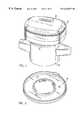
- FIG. 1is a perspective view of an interface management unit attached to a water meter in accordance with the present invention
- FIG. 2is a perspective view of an adapter ring used to attach the interface management unit to the meter;
- FIG. 3is an exploded perspective view of the internal structure of an interface management unit
- FIG. 4is a front elevational view of a gateway node
- FIG. 5Ais a schematic view of interface management units for water, gas and electric meters interfacing with a remote gateway node and the utility service provider;
- FIG. 5Bis a schematic view of interface management units for water, gas and electric meters interfacing with a proximate relay node, a remote gateway node and the utility service provider;
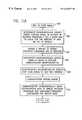
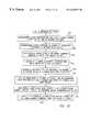
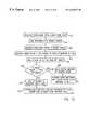
- FIG. 6Ais a flow diagram of an automatic meter reading data communication system
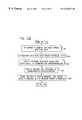
- FIG. 6Bis a flow diagram of an alternative automatic meter reading data communication system
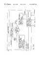
- FIG. 7is a block diagram of the interface management unit circuitry
- FIG. 8is a block diagram of the RF transceiver of the interface management unit, the relay node and the gateway node;
- FIG. 9is a block diagram of the frequency synthesizer portion of the RF transceiver of FIG. 8;
- FIG. 10is a block diagram of the gateway node circuitry
- FIG. 11Ais a flow diagram of the operation of the interface management unit in power management and communication
- FIG. 11Bis a continuation of the flow diagram of FIG. 11A;
- FIG. 11Cis a continuation of the flow diagram of FIG. 11B;
- FIG. 12is a flow diagram of interface management unit commissioning
- FIG. 13is a flow diagram of the interface management unit virtual shut-off function
- FIG. 14is a functional diagram of the automatic meter reading data communication system
- FIG. 15Ais a flow diagram of the WAN handler portion of the data communication system of FIG. 14;
- FIG. 15Bis a flow diagram of the message dispatcher portion of the data communication system of FIG. 14;
- FIG. 15Cis a flow diagram of the RF handler portion of the data communication system of FIG. 14;
- FIG. 15Dis a flow diagram of the scheduler portion of the data communication system of FIG. 14.
- FIG. 15Eis a flow diagram of the data stores portion of the data communication system of FIG. 14 .
- the present inventionprovides an automatic meter reading data communication system 20 having an interface management unit 22 which communicates with a gateway node 24 located remote from the interface management unit 22 .
- Located in between the interface management unit 22 and the gateway node 24may be a relay node 26 , FIGS. 5B and 6B, that is located proximate to the interface management units 22 and provides additional communication power from the interface management unit 22 to the gateway node 24 .
- the communication range of the interface management unit 22is approximately 400 ft. Therefore, if a gateway node 24 is farther than 400 ft. away from an interface management unit 22 then a relay node 26 is needed to retransmit the message from the interface management unit 22 to the gateway node 24 .
- the RF communication ranges of the relay node 26 and the gateway node 24are approximately one mile.
- the interface management unit 22is primarily a data gathering device that may be attached to a residential utility meter 28 such as a water or gas meter, for transmitting gathered data relating to consumed amounts of commodities, such as water or gas usage, to the gateway node 24 .
- the interface management unit 22may also interface with other devices to monitor such things as home security, environmental conditions, personal medical conditions, the existence of smoke or carbon monoxide, etc.
- the gateway node 24interrogates interface management unit 22 to obtain the gathered data by a radio frequency (RF) communication link and then transmits that data to a utility service provider 30 over a fixed wide area network (WAN) 34 .
- RFradio frequency
- FIGS. 5A and 6Aa plurality of interface management units 22 attached to meters 28 for different commodities, such as water, gas and electric, communicate over a local area network (LAN) 32 to a gateway node 24 which transmits the commodity data from interface management units 22 to a utility 30 over a fixed common carrier wide area network (WAN) 34 .
- the gateway node 24provides end to end communications from the meter 28 to the utility 30 .
- a first link in the data communication systemis a two-way 900 MHz spread spectrum LAN 32 .
- the second link within the data communication systemis designed to be any commercially available two-way common carrier WAN 34 .
- a gateway node 24must be within the communication range of the interface management unit 22 which is approximately 400 ft. However, if the gateway node 24 is outside of the interface management unit's communication range then a relay node 26 may be provided to retransmit the data from the interface management unit 22 to the gateway node 24 as shown in FIGS. 5 B and is 6 B.
- the operating range of the relay nodeis approximately one mile.
- the relay node 26utilizes the same RF transceiver circuitry as the interface management unit 22 and the gateway node 24 .
- the LAN communication links 32 A and 32 B shown in FIG. 6Btechnically comprise the same link as LAN 32 shown in FIG. 6 A. The only difference is that the gateway node 24 in FIG. 6B is outside the communication range of interface management unit 22 thus requiring a retransmission of the data by relay node 26 .
- the data gathered from interface management units 22is typically provided to computers in the utility company and used to generate billings or commodity usage data.
- interface management unit 22is an integrated unit that attaches to a water, gas or electric utility meter 28 by adapter ring 36 .
- the interface management unit 22replaces the register head of the meter 28 using the adapter ring 36 to retrofit the interface management unit 22 onto the existing meter body 28 for the meters of a wide variety of manufacturers. This is accomplished by the use of a plurality of different adapter rings 36 and programmable software within the interface management unit 22 .
- FIG. 3shows the internal structure of interface management unit 22 .
- Interface management unit 22comprises top cover 40 , bottom cover 46 , and two printed circuit boards 42 and 44 .
- Printed circuit board 42is preferably an RF antenna with a cut out 48 for the liquid crystal display 38 on printed circuit board 44 .
- the liquid crystal display 38displays meter reading, unit of measure, tamper and status conditions.
- Printed circuit board 44includes various components and connectors as detailed in the block diagram of FIG. 7 .
- Interface management unit 22is powered by a battery 50 .
- the compact integrated design and adaptability with various meters and meter brandspresents a cost savings from prior art systems.
- the interface management unit 22is an integrated, digital encoder and two-way wireless transceiver that monitors the activity of a utility meter 28 , such as a water, gas or electric meter, ascertaining commodity usage by counting pulses produced by a rotating vane in the meter, and communicates commodity usage data, via a RF local area network (LAN) to a relay node 26 or a gateway node 24 .
- a utility meter 28such as a water, gas or electric meter
- the events counted by interface management unit 22are usually pulses generated by a turbine or other transducer element responsive to commodity flow through the meter. Additional features, such as valve actuation outputs and tamper inputs, may also be provided in interface management unit 22 .
- communication between the interface management unit 22 and the relay node 26 or gateway node 24is preferably established using a two-way 900 MHz direct sequence, spread spectrum data transmission technique having a plurality of channels in the employed frequency band.
- the interface management unit 22performs its automatic meter reading functions in response to requests from the utility, from preprogrammed scheduled readings, or from spontaneous alarm messages. These automatic meter reading functions include monthly usage readings, remote first and final meter readings, real-time tamper detection and notification, virtual shut-off function, and alarm system functions.
- the interface management unit 22 attached to a water meteris capable of leak detection and low flow reporting, and is submersible in pit applications without a fixed antenna attachment.
- An interface management unit 22 attached to a gas meteris capable of runaway meter detection.
- the interface management unit 22also performs security and information management tasks.
- the interface management unit 22is installed using a portable computer to program utility identification numbers, meter settings and readings, units of measure, and alarm set points. Once the interface management unit is installed, it is linked to a gateway node over two-way wireless LAN 32 . As mentioned above, the interface management unit 22 does not need to be awakened in order to send data. The interface management unit can either initiate a communication on its own, perform previously programmed scheduled readings or respond to requests from the utility through the gateway node 24 .
- the gateway node 24is shown in FIG. 4 .
- the gateway node 24is typically located on top of a power pole so that it may act as a communication node between LAN 32 and WAN 34 . It thus functions as the LAN to WAN connection.
- the gateway node 24includes an antenna 52 for receiving and transmitting data over the communication links, and a power line carrier connector 54 for connecting a power line to power the gateway node 24 .
- the gateway node 24may also be solar powered.
- the compact designallows for easy placement on any existing utility pole or similarly situated elevated location.
- the gateway node 24provides end to end communications from the meter to the utility.
- the wireless gateway node 24interfaces with the interface management unit 22 over a two-way 900 MHz spread spectrum LAN 32 . Also, the gateway node 24 will interface and be compatible with any WAN 34 for communicating with the utility.
- the gateway node 24is field programmable to meet a variety of data reporting needs.
- the gateway node 24receives data requests for water, gas and electric meter data, interrogates the meter and forwards usage information, as well as condition status data, over the WAN 34 to the utility 30 . It also provides communication links with other safety, security and information nodes. The gateway node 24 exchanges data with certain, predetermined, interface management units for which it is responsible, and “listens” for signals from those interface management units. The gateway node 24 does not store data for extended periods, thus minimizing security risks. The gateway node's RF communication range is typically one mile.
- the relay node 26acts as an intermediate transceiver to provide additional power boost to get the RF signal from the interface management unit 22 to the gateway node 24 .
- the relay node 26can be either solar powered or powered through a power line carrier connection.
- the same RF transceiver circuitry found in the interface management unit 22 and the gateway node 24is utilized in the relay node 26 .
- WANwide area network
- PCSpersonal communication services
- CDPDcellular digital packet data
- satellitesmay be used to communicate data between the gateway nodes and the utility.
- the data communication systemutilizes channelized direct sequence spread spectrum transmissions for communicating between the interface management units, relay nodes and gateway nodes.
- FIG. 7shows a block diagram of a half duplex channelized, direct sequence, spread spectrum circuit board 44 within interface management unit 22 .
- the circuit boardis composed of four major functional components; supervisory microcontroller 56 , communication microcontroller 58 , spread spectrum processor 60 , and radio frequency (RF) transceiver 62 .
- supervisory microcontroller 56supervisory microcontroller 56
- communication microcontroller 58communication microcontroller 58
- spread spectrum processor 60a radio frequency (RF) transceiver 62 .
- RFradio frequency
- supervisory microcontroller 56carries out the primary interface function between interface management unit 22 and meter 28 . This includes detecting and accumulating pulses from utility meter transducer 64 . The accumulated pulse totalization may be converted to corresponding units of commodity volume and the results displayed on liquid crystal display (LCD) 38 to provide a visual indication of commodity consumption.
- the supervisory microcontrolleralso monitors inputs from tamper switch 66 for unauthorized use or status reporting.
- the microcontroller 56is coupled to a low battery detector 68 for monitoring battery power.
- This microcontroller 56also includes the data systems supervisory timer which controls power management functions. During normal operation supervisory microcontroller 56 is running at a predetermined clock speed, for example 32.768 KHz, which is provided by an external crystal oscillator 70 . All other components in the interface management unit 22 are either in a low power “sleep” mode or have power completely removed from them. Periodically, supervisory microcontroller 56 applies power to the other components and “wakes” them “up” to ascertain whether an interrogating RP signal from gateway node 24 is present or not. The wake up power application may occur every 2-8 seconds, typically. If an interrogatory signal is not present, power is removed from the other components or they are returned to the low power sleep mode. This technique is used to conserve battery power, and thus extend battery life. If a valid interrogatory signal is present, interface management unit 22 will transmit data to relay node 26 or gateway node 24 .
- a predetermined clock speedfor example 32.768 KHz
- Supervisory microcontroller 56may comprise the microprocessor component sold by Toshiba of Japan under the designation TMP47P422VN.
- Communication microcontroller 58is responsible for all aspects of radio frequency (RF) communication management in interface management unit 22 including determining whether or not any given RF signal is a valid interrogating signal and performing the actual data interchange with gateway node 24 .
- Microcontroller 58provides control information to spread spectrum processor 60 and RP transceiver 62 to control spread spectrum protocol and RF channelization.
- communication microcontroller 58when communication microcontroller 58 is not performing communication activities it is in a “sleep” mode.
- Communication microcontroller 58may comprise the microprocessor component sold by Microchip of Chandler, Ariz. under the designation PIC16LC74-04/L.
- data communication system 20 of the present inventionpreferably employs spread spectrum communications between interface management unit 22 and gateway node 24 , or relay node 26 .
- the spread spectrum communication techniquemakes use of a sequential noise-like signal structure, for example, pseudo-noise (PN) codes to spread a normally narrowband information signal over a relatively wide band of frequencies.
- PNpseudo-noise
- the receivercorrelates these signals to retrieve the original information signal.
- the techniquemay be further understood by reference to U.S. Pat. No. 5,166,952 and the numerous publications cited therein.
- Spread spectrum processor 60functions to perform spread spectrum encoding of the data from communication microcontroller 58 provided to RF transceiver 62 and decoding of the spread spectrum data from the RF transceiver.
- the spread spectrum processoralso generates the 2.4576 MHz clock signal for communication microcontroller 58 and the frequency synthesizer 72 of RF transceiver 62 .
- the spread spectrum processor 60may comprise an application specific integrated circuit (ASIC) gate array made and sold by Cylink Corporation of Sunnyvale, California, under the designation SST32ADL which contains a 9.8304 MHz crystal oscillator 74 , data registers, and encoding/decoding logic.
- ASICapplication specific integrated circuit
- the encoding/decoding logic of spread spectrum processor 60samples the incoming serial data from the communication microcontroller and converts it into a 32 bit pseudo-noise (PN) encoded data stream at a rate which is divided from crystal oscillator 74 by a factor of 192.
- the PN sequencerepresents two data input samples. Each pair of the serial data bits or “dibits” is represented by a unique 32 bit PN sequence.
- FIG. 8shows a block diagram of RF transceiver 62 of interface management unit 22 .
- Communication to and from interface management unit 22may be carried out in one of a preselected number, for example 24 channels in a preselected frequency band, for example 902-928 MHz.
- Interface management unit 22receives data and transmits a response on a single RF channel which is the same for both transmit and receive operation.
- the specific RF channel used for communicationis chosen during commissioning and installation of the unit and loaded into memory.
- the RF channelis chosen to be different from the operating channels of other, adjacent interface management units, thereby to prevent two or more interface management units from responding to the same interrogation signal.
- Frequency synthesizer 72performs the modulation and demodulation of the spread spectrum data provided by spread spectrum processor 60 onto a carrier signal and demodulation of such data from the carrier signal.
- the RF transceiverhas separate transmitter 76 and receiver 78 sections fed from frequency synthesizer 72 which is shared by the two sections.
- Antenna 80is coupled through band pass filter 82 to a transmit-receive antenna switch 84 , operated by communication microcontroller 58 , which connects the desired one of transmitter 76 or receiver 78 to antenna 80 .
- the output of spread spectrum processor 60 to frequency synthesizer 72comprises a 2.4576 MHz reference frequency signal in conductor 86 and a PN encoded base band signal in conductor 88 .
- Frequency synthesizer 72may comprise a National Semiconductor LMX2332A Dual Frequency Synthesizer.
- the direct sequence modulation technique employed by frequency synthesizer 72uses a high rate binary code (PN code) to modulate the base band signal.
- PN codebinary code
- the resulting spread signalis used to modulate the transmitter's RF carrier signal.
- the spreading codeis a fixed length PN sequence of bits, called chips, which is constantly being recycled. The pseudo-random nature of the sequence achieves the desired signal spreading, and the fixed sequence allows the code to be replicated in the receiver for recovery of the signal. Therefore, in direct sequence, the base band signal is modulated with the PN code spreading function, and the carrier is modulated to produce the wide band signal.
- Minimum shift keying (MSK) modulationis used in order to allow reliable communications, efficient use of the radio spectrum, and to keep the component count and power consumption low.
- the modulation performed by frequency synthesizer 72is minimum shift keying (MSK) at a chip rate of 819.2 Kchips per second, yielding a transmission with a 6 dB instantaneous bandwidth of 670.5 KHz.
- the receiver bandwidth of interface management unit 22is nominally 1 MHz, with a minimum bandwidth of 900 KHz.
- Frequency resolution of the synthesizeris 0.2048-MHz, which will be used to channelize the band into 24 channels spaced a minimum of 1.024 MHz apart. This frequency channelization is used to minimize interference between interface management units within a common communication range as well as providing growth for future, advanced features associated with the data communication system.
- Frequency control of the RF related oscillators in the systemis provided by dual phase locked loop (PLL) circuitry within frequency synthesizer 72 .
- the phase locked loopsare controlled and programmed by communication microcontroller 58 via a serial programming control bus 100 , FIG. 7 .
- frequency synthesizer 72produces two RF signals which are mixed together in various combinations to produce a transmission carrier and to demodulate incoming RF signals.
- the transmission carrieris based on frequencies in the 782-807 MHz range provided in conductor 102 and the demodulation signal is based on frequencies in the 792-817 MHz range provided in conductor 104 . These signals may be referred to as RF transmit and RF receive local oscillation signals.
- Table Iis a summary of the transmission channel frequencies and associated frequency synthesizer transmit/receive outputs in conductors 102 and 104 .
- the signals in the tableare provided by the two PLL sections in the dual frequency synthesizer 72 .
- a third signalwhich is fixed at 120.4224 MHz, is also supplied by the dual frequency synthesizer. This signal is supplied to conductor 106 and may be referred to as the intermediate frequency (IF) local oscillation signal.
- IFintermediate frequency
- RF receiver section 78 of RF transceiver 62includes low noise amplifier 108 , the input of which is connected to transmit-receive switch 84 .
- the output of low noise amplifier 108is connected to intermediate frequency (IF) signal mixer 110 .
- the other input to signal mixer 110is the output from frequency synthesizer 72 in conductor 104 .
- the output of signal mixer 110is an intermediate frequency signal which is passed through band pass filter 112 to intermediate frequency signal mixer 114 .
- the other input to intermediate frequency signal mixer 114is the 120.4224 MHz fixed frequency signal from frequency synthesizer 72 in conductor 106 .
- Intermediate frequency signal mixer 114converts the received signals to a final intermediate frequency of, for example, 9.8304 MHz.
- the intermediate frequency signal from intermediate frequency signal mixer 114is passed through band pass limiting circuitry comprising band pass filter 116 , amplifier 118 , band pass filter 120 , and amplifier 122 .
- the signal from amplifier 122is provided to quadrature frequency discriminator 124 comprised of band pass filter 126 and signal mixer 128 .
- the output of frequency discriminator 124is provided to a linear phase low pass filter 130 and a voltage comparator 132 .
- the output of voltage comparator 132 in conductor 134comprises the received baseband data signal for interface management unit 22 .
- the signal in conductor 134is provided to spread spectrum processor 60 , and in turn, to communication microcontroller 58 .
- frequency synthesizer 72provides a signal having a frequency in the 782-807 MHz range in conductor 102 , modulated with the data to be transmitted.
- RF transmitter section 76includes signal mixer 136 which mixes the signal in conductor 102 with the fixed frequency IF local oscillator signal in conductor 106 . This results in an RF signal which ranges between 902 MHz and 928 MHz.
- the signalis filtered by bandpass filter 138 to reduce harmonics and out of band signals, amplified by a medium power amplifier 138 and supplied to transmit/receive switch 84 .
- FIGS. 11A-11Cis a flow diagram of the power management and system communication of the interface management unit 22 in accordance with the present invention.
- a request communications episodecomprises three different phases: a wake-up interval of the communications hardware of the interface management unit, sometimes called “blinking”; the polling data from the gateway node; and a response by the interface management unit.
- the responsemay include the meter count indicative of the amount of commodity consumed.
- the interface management unitis operated in a pulsed mode where it wakes up from a sleep mode periodically, typically 2-8 seconds.
- the interface management unitstarts off in sleep mode as shown in FIGS. 11A by reference numeral 300 .
- communication microcontroller 58will activate RF receiver 78 periodically for a short time, or “blink” interval, to determine the presence of a signal from gateway node 24 on the RF channel established for the interface management unit. See step 302 .
- the signal from gateway node 24comprises spread spectrum PN data recognizable by interface management unit 22 as a valid interrogator signal. If no spread spectrum PN data is seen, or the data which is there is determined to be invalid, receiver 78 shuts down or goes back to “sleep.” If the PN sequence is recognized as valid, receiver 78 will remain on until the communication episode is complete.
- gateway node 24Since the interface management unit 22 is not listening continuously for data it is necessary for gateway node 24 to “wake up” the interface management unit before sending data to it. Polling or commissioning data will be sent only after the interface management unit has had sufficient time to wake up. It will respond with the requested information shortly after polling has terminated. Once the communication episode is finished the interface management unit will resume its normal behavior of blinking to test for the presence of a signal from the data interrogator in the RF channel.
- a blink cyclebegins with supervisory microcontroller 56 asserting the power control line low which applies power to spread spectrum processor 60 and starts all oscillators in the interface management unit 22 , step 304 .
- the supervisory microcontrollerAfter the supervisory microcontroller has allowed time for the oscillators to start and stabilize, it provides a pulse on wake up line 142 to activate communication microcontroller 58 , step 306 .
- Communication microcontroller 58generates a“keep alive” signal to supervisory microcontroller 56 in line 144 to indicate to supervisory microcontroller 56 that it has activities in progress and that supervisory microcontroller 56 must continue to maintain the components of interface management unit 22 in the operations condition. This occurs in step 308 .
- step 310 in the communication processis polling by gateway node 24 .
- gateway node 24For any meaningful data interchange to occur it is necessary to load spread spectrum processor 60 with its PN codes and mode control data. In this code, every pair of serial data bits, termed a “dibit”, is represented by a unique 32 bit PN sequence. It is also necessary to load MSK frequency synthesizer 72 with the proper channel programming data via control bus 100 .
- Spread spectrum datais transferred between communication microcontroller 58 and spread spectrum processor 60 via 8 bit control bus 146 .
- frequency synthesizer 72After frequency synthesizer 72 is programmed to the correct RF channel, it is time to sample the RF channel for valid spread spectrum data. See steps 312 and 314 . Direct sequence spread spectrum serial data is transferred at a rate of 2400 bits per second for all communication episodes.
- RF transceiver 62When RF transceiver 62 is stabilized, there will be demodulated data available at the input of spread spectrum processor 60 . In the event that valid codes are received, spread spectrum processor 60 will assert the “lock detect” signal 148 to communication microcontroller 58 at step 316 . If a lock detect signal is not asserted in conductor 148 within a predefined time period, interface management unit 22 will revert back to its sleep mode. Assuming, however, that lock detect did occur, there will be serial data present at the input of communication microcontroller 58 . See step 318 . When gateway node 24 has finished sending its packet of data it will cease transmitting over the RF channel, causing a loss of the lock detect signal at some random time after the end of the transmission. Once lock detect is lost, power to RF receiver 78 is removed. See step 320 .
- the serial data at the input to communication microcontroller 58is decoded by the communication microcontroller and the validity of the received message is determined. If the message is correctly formatted and the serial number data contained in the message matches the serial number of the interface management unit that received it, then data is interchanged with the supervisory microcontroller 56 via serial data conductors 150 , 152 , and 154 , with communication microcontroller 58 acting as the master. A message is sent from communication microcontroller 58 to supervisory microcontroller 56 . When supervisory microcontroller 56 responds, it will reverse the direction of the master/slave relationship on the serial interface system by a asserting the slave enable signal in conductor 156 . Data is then sent back using the supervisory microcontroller as the serial interface clock. The slave enable signal is removed when the message is completed. See steps 322 , 324 , 326 , and 328 .
- This data interchangewill occur for every received message except a valve actuation message and a request for serial number message. If there is no data interchange required, a response to that effect is sent.
- a return message to gateway node 24is formulated at step 330 .
- communication microcontroller 58When communication microcontroller 58 is ready to transmit, it must reprogram frequency synthesizer 72 to change its frequency offset. This is accomplished over control bus 100 .
- the RF transmitter 76 and spread spectrum processor 60are then enabled to transmit a response by the interface management unit 22 . After spread spectrum processor 60 has had time to stabilize, the return message is sent. This message is terminated by disabling spread spectrum processor 60 and RF transmitter 76 . See steps 332 through 340 .
- RF receiver 78is activated once again to check for more incoming data as at step 342 . This is done to allow multiple messages to be interchanged once interface management unit 22 has been awakened without the need to complete a wake up cycle for each message. If communication microcontroller 58 does not detect the presence of any incoming messages within a given time period it will cause interface management unit 22 to return to its sleep mode. Step 344 . Frequency synthesizer 72 is commanded to revert to its low power mode by a message on control bus 100 and the keep alive signal in conductor 144 to supervisory microcontroller 56 is released to tell the supervisory microcontroller that communication has ended. Step 346 . Supervisory microcontroller 56 then removes power to the remaining portions of interface management unit 22 . Step 348 .
- Communication between supervisory microcontroller 56 and the communication microcontroller 58is accomplished via the serial interface bus comprised of signals 150 , 152 and 154 .
- All interprocessor communicationconsists of a control code byte, a data byte, and a check sum byte. Messages that request information consist of only the control code byte and the check sum byte.
- the check sumis a twos complement check sum.
- An example communications episodecan be described as follows:
- the RF receiver 78 of interface management unit 22wakes up, sees no data, and goes back to sleep. The second time the RF receiver wakes up it sees the spread spectrum PN sequence from gateway node 24 , recognizes it, and waits for polling data to emerge from spread spectrum processor 60 . Once the unit is awake, it will receive and decode the polling message from gateway node 24 and formulate an appropriate response.
- gateway node 24transmits a continuous idle condition to allow spread spectrum processor 60 to synchronize and to assure that the interface management unit blink window is open long enough to see the incoming PN sequences. Once code lock is achieved the listen interval will extend to accommodate the incoming data, because the wake up is deemed successful if code lock is achieved. If code lock occurs but a message fails to be recognized or no data is seen within the specified time window, then the communication microcontroller 58 will go back to sleep.
- the gateway node 24After the unit 22 has been successfully awakened, the gateway node 24 must command it to perform one of many predefined functions. When the unit responds to a message, it echoes the control word back with the highest order bit cleared along with the meter serial number as a confirmation of the origin of the return message. This scheme should assure that gateway node 24 will not respond to any return data which did not originate from the intended interface management unit 22 .
- Each data messagestarts with a predefined control code followed by the necessary data and a check sum of all bytes up to the check sum byte.
- the check sumis calculated by taking the twos complement of the sum of all bytes preceding the check sum byte. This allows testing the check sum by adding all of the message bytes, including the check sum, and testing for a result of zero.
- Data types used for data interchangeinclude the following: meter count, utility serial number, RF channel, unit of measure, meter type, conversion factor, error code, actuator port, transmit, count, company identifier, software version and manufacturer serial number.
- FIG. 10shows a block diagram of the gateway node circuitry.
- the RF transceiver section 156 of gateway node 24is the same as the RF transceiver section 62 of interface management unit 22 .
- Spread spectrum processor 158is also the same as spread spectrum processor 60 in interface management unit 22 so that frequency synthesis, modulation, demodulation, and spread spectrum control in gateway node 24 are equivalent to that found in interface management unit 22 .
- WAN interface module 162may incorporate electronic circuitry for a two-way pager, power line carrier (PLC), satellite, cellular telephone, fiber optics, cellular digital packet data (CDPD) system, personal communication services (PCS), or other fixed wide area network (WAN) system.
- PLCpower line carrier
- CDPDcellular digital packet data
- PCSpersonal communication services
- WANwide area network
- the construction of WAN interface module 162 and initialization microcontroller 160may change depending on the desired WAN interface.
- RF channel selectionis accomplished through an RF channel select bus 164 which interfaces directly with the initialization microcontroller 160 .
- Initialization microcontroller 160controls all node functions including programming spread spectrum processor 158 , RF channel selection in frequency synthesizer 166 of RF transceiver 156 , transmit/receive switching, and detecting failures in WAN interface module 162 . Upon power up, initialization microcontroller 160 will program the internal registers of spread spectrum processor 158 , read the RF channel selection from the interface management unit 22 , and set the system for communication at the frequency corresponding to the channel selected by the interface management unit 22 .
- Selection of the RF channel used for transmission and receptionis accomplished via the RF channel select bus 164 to initialization microcontroller 160 .
- Valid channel numbersrange from 0 to 23.
- the inputshave been debounced through software.
- Channel selection datamust be present and stable on the inputs to initialization microcontroller 160 for approximately 250 ⁇ s before the initialization microcontroller will accept it and initiate a channel change. After the channel change has been initiated, it takes about 600 ⁇ s for frequency synthesizer 166 of RF transceiver 156 to receive the programming data and for the oscillators in the frequency synthesizer to settle to the changed frequency.
- Channel selectionmay only be completed while gateway node 24 is in the receive mode. If the RF channel select lines are changed during the transmit mode the change will not take effect until after the gateway node has been returned to the receive mode.
- initialization microcontroller 160begins its monitoring functions. When gateway node 24 is in the receive mode, the initialization microcontroller 160 continuously monitors RF channel select bus 164 to determine if a channel change is to be implemented.
- gateway node 24For receiving data, gateway node 24 monitors the interface management unit 22 to determine the presence of data. Some additional handshaking hardware may be required to sense the presence of a spread spectrum signal.
- An alarm messageis sent automatically by interface management unit 22 in the event of a tamper or alarm condition of meter 28 .
- the messageis sent periodically until the error has cleared.
- Gateway node 24must know how many bytes of data it is expecting to see and count them as they come in. When the proper number of bytes is received, reception is deemed complete and the message is processed. Any deviation from the anticipated number of received bytes may be assumed to be an erroneous message.
- initialization microcontroller 160monitors the data line to detect idle conditions, start bits, and stop bits. This is done to prevent gateway node 24 from continuously transmitting meaningless information in the event a failure of WAN interface module 162 occurs and also to prevent erroneous trailing edge data from being sent which cannot terminate transmissions in a timely fashion.
- the initialization microcontroller 160will not enable RF transmitter 168 of RF transceiver 156 unless the data line is in the invalid idle state when communication is initiated.
- a second watchdog function of initialization microcontroller 160 when gateway node 24 is in the transmit modeis to test for valid start and stop bits in the serial data stream being transmitted. This ensures that data is read correctly.
- the first start bitis defined as the first falling edge of serial data after it has entered the idle stage. All further timing during that communication episode is referenced from that start bit. Timing for the location of a stop bit is measured from the leading edge of a start bit for that particular byte of data.
- Initialization microcontroller 160measures an interval which is 9.5 bit times from that start bit edge and then looks for a stop bit. Similarly, a timer of 1 bit interval is started from the 9.5 bit point to look for the next start bit. If the following start bit does not assert itself within 1 bit time of a 9.5 bit time marker a failure is declared. The response to a failure condition is to disable RF transmitter 168 .
- An interface management unitWhen an interface management unit is initially installed it does not contain any utility serial number, meter scaling, or RF channel information. These constants must be programmed during installation and commissioning to allow the interface management unit to interface with the utility billing software and the meter type.
- a flow diagram of the interface management unit commissioningis shown in FIG. 12 .
- an interface management unitWhen an interface management unit is manufactured it will default to the first RF channel in its internal frequency list. This known channel will be used to speed production line testing and interface management unit commissioning.
- a commissioning deviceWhen an interface management unit is installed, a commissioning device will program the interface management unit with a utility serial number, meter scaling characteristics, and RF channel selection data. See step 360 . It will then try to obtain a response on the default RF channel first. If there is no response from the default channel, the commissioning device will move to the next channel on the frequency list and repeat the process until the interface management unit responds. This allows a commissioning device to set up new meters as well as to recommission meters which are already in the field.
- interface management unitIn order for the interface management unit to function as a part of the network and to co-exist with other interface management units in the area it may be necessary to coordinate their operating frequencies to minimize data collisions. This task must be performed at the time of interface management unit commissioning and will be the responsibility of the commissioning device. In a fixed local area network setting all interface management units could occupy the same frequency since they are accessed one at a time by serial number.
- Each interface management unithas a finite distance over which it can transmit and receive RF signals, typically 400 feet.
- a gateway nodeIn order for a gateway node to establish successful communication with an interface management unit it must be within that finite distance over which it can transmit and receive RF signals, otherwise it is necessary to install a relay node to boost the RF signal.
- Assignment of interface management unit frequencieswill be performed by the commissioning device at the time of installation. This will be accomplished through the use of an RF survey to determine the presence of interfering interface management units or other conflicting RF signals. See step 362 .
- the commissioning deviceUpon survey initiation the commissioning device will perform a send serial numbers message on the first or default RF channel, at step 364 . An interface management unit within range of the commissioning device should respond since this is a serial number independent message. If the commissioning device does not get a response on this channel, it will label it as okay for use and the survey will stop. However, should the channel be occupied, the commissioning device will move on to the next channel in the list as shown in step 366 . This process will repeat itself until an unoccupied channel is located or all 24 channels have been exhausted. See step 368 . Once an unoccupied RF channel is located, the commissioning device programs the utility serial number, the operating RF channel, and all remaining meter-parameters into the interface management unit's memory. See steps 370 and 372 . The utility serial number, RF channel and other meter parameters may be changed at any time by a “set serial numbers” message from the commissioning device as outlined in step 374 .
- the same RF frequenciesmay be used over and over again.
- this channelbecomes available for use again by another interface management unit.
- This planis preferable to a preassigned frequency plan since it takes into account actual radio propagation conditions in the area and does not require extensive preplanning or a complicated map of channels.
- FIG. 13shows a flow diagram of the virtual shut-off function of the interface management unit in accordance with the present invention.
- the virtual shut-off function of the interface management unitis used for situations such as a change of ownership where a utility service is to be temporarily inactive. When a residence is vacated there should not be any significant consumption of utilities at that location. If there is any meter movement, indicating either a leak or unauthorized usage, the utility needs to be notified. This tamper mode condition provides a means of flagging and reporting meter movement beyond a preset threshold value.
- Activation of the virtual shut-off modeis accomplished through the “set virtual threshold” message, defined as a meter count which the interface management unit is not to exceed.
- the relay node, gateway node, commissioning device, or other interface management unit communication devicemust read the meter count, steps 376 and 378 , add whatever offset is deemed appropriate, step 380 , send the result to the interface management unit as a “set virtual shut-off” message at step 382 .
- the interface management unitwill then enable the virtual shut-off mode at step 384 .
- the interface management unitthen accumulates the meter counts at step 386 .
- the interface management unitsends a “send alarm” message to the gateway node until a “clear error code” message is issued in response by the gateway node as detailed in steps 388 and 390 .
- the interface management unitcontinues to monitor the meter count at step 392 .
- the virtual shut-off modemay be canceled at any time by a “clear error code” message from the gateway node at step 394 .
- step 392the unit continues to count (step 392 ) until the preset threshold count is attained or until operation in the virtual shut-off mode is canceled (step 394 ).
- FIG. 14shows a functional flow diagram of the automatic meter reading data communication system of the present invention in which the components are described as functional blocks.
- a flow diagramincludes the main functional components of the gateway note 24 which include a message dispatcher 200 , an RF handler 202 , a WAN handler 204 , a data stores component 206 and a scheduler component 208 .
- the data stores and scheduler componentscomprise data that is preprogrammed into the gateway node's memory.
- the gateway nodeinterfaces with an interface management unit or a relay node 210 over the two-way wireless LAN.
- a gateway node 24also interfaces with a utility service provider over the fixed common carrier WAN.
- FIGS. 15Ais a detailed functional diagram of the WAN handler 204 of FIG. 14 .
- the utility. 212may initiate a request for data from the interface management unit 210 by sending a data stream over the WAN.
- the WAN handler of the gateway nodereceives the WAN data stream, creates a WAN message, verifies the utility ID of the sender from the data stores 206 and routes the WAN message to the message dispatcher 200 in the gateway node.
- the message dispatcher 200receives the WAN message from the WAN handler and determines the request from the utility 212 .
- the message dispatcher 200determines that the end recipient or target is the interface management unit or relay node 210 .
- the message dispatcherthen verifies the interface management unit ID from the data stores 206 , creates an RF message and routes the RF message to the RF handler 202 .
- the RF handlerreceives the RF message from the message dispatcher 200 , selects a proper RF channel, converts the RF message to an RF data stream, sends the RF data stream to the interface management unit or relay node 210 over the LAN and waits for a response.
- the interface management unitthen responds by sending an RF data stream over the LAN to the RF handler 202 of the gateway node 24 .
- the RF handler 202receives the RF data stream, creates an RF message from the RF data stream and routes the RF message to the message dispatcher 200 . As shown in FIG.
- the message dispatcherreceives the RF message, determines the target utility for response from the data stores 206 , creates a WAN message and routes the WAN message to the WAN handler 204 .
- the WAN handler 204receives the WAN message from the message dispatcher, converts the WAN message to a WAN data stream and sends the WAN data stream to the utility over the fixed common carrier WAN, as shown in FIG. 15A to complete the communication episode.
- a communication episodecan also be initiated by scheduled readings preprogrammed into the scheduler 208 of the gateway node as shown in FIG. 15D.
- a list of scheduled reading timesis preprogrammed into memory within the gateway node 24 .
- the scheduler 208runs periodically when a scheduled reading is due. When it is time for a scheduled reading, the scheduler 208 retrieves interface management unit or relay node information from the data stores 206 , creates an RF message and routes the RF message to the RF handler 202 , receives the RF message, selects a proper RF channel, converts the RF message to an RF data stream, sends the RF data stream to the interface management unit or relay node 210 and waits for a response.
- the interface management unitthen responds with an RF data stream to the RF handler 202 .
- the RF handler 202receives the RF data stream, creates an RF message from the RF data stream and routes the RF message to the message dispatcher 202 .
- the message dispatcherreceives the RF message, determines the target utility for response from the data stores 206 , creates a WAN message and routes the WAN message to the WAN handler 204 .
- the WAN handlerreceives the WAN message, converts the WAN message to a WAN data stream and sends the WAN data stream to the utility 212 .
- the utilitymay request data that is stored within the gateway node's memory.
- the utilityinitiates the communication episode by sending a WAN data stream to the WAN handler 204 .
- the WAN handlerreceives the WAN data stream, creates a WAN message, verifies the utility ID of the sender in the data stores 206 and routes the WAN message to the message dispatcher 200 .
- the message dispatcher 200receives the WAN message and determines the request from the utility 212 .
- the message dispatcher 200determines the target of the message.
- the gateway nodeperforms the requested task, determines that the requesting utility is the target utility for a response, creates a WAN message and routes the WAN message to the WAN handler 204 .
- the WAN handler 204receives the WAN message, converts the WAN message to a WAN data stream and sends the WAN data stream to the utility 212 .
- the last type of communication episodeis one which is initiated by the interface management unit.
- the interface management unitdetects an alarm or tamper condition and sends an RF data stream to the RF handler 202 of the gateway node 24 .
- the RF handler 202receives the RF data stream, creates an RF message from the RF data stream and routes the RF message to the message dispatcher 200 .
- the message dispatcher 200receives the RF message, determines the target utility for response from the data stores 206 , creates a WAN message and routes the WAN message to the WAN handler 204 .
- the WAN handlerreceives the WAN message, converts the WAN message to a WAN data stream and sends the WAN data stream to the utility.
- FIG. 15Drepresents information or data that is preprogrammed into the gateway node's memory. Included within the memory is a list of scheduled reading times to be performed by the interface management unit. These reading times may correspond to monthly or weekly usage readings, etc.
- FIGS. 15Erepresents data or information stored in the gateway node's memory dealing with registered utility information and registered interface management unit information.
- This dataincludes the utility identification numbers of registered utilities, interface management unit identification numbers of registered interface management units, and other information for specific utilities and specific interface management units, so that the gateway node may communicate directly with the desired utility or correct interface management unit.
Landscapes
- Engineering & Computer Science (AREA)
- Power Engineering (AREA)
- Computer Networks & Wireless Communication (AREA)
- Physics & Mathematics (AREA)
- General Physics & Mathematics (AREA)
- Human Computer Interaction (AREA)
- Arrangements For Transmission Of Measured Signals (AREA)
Abstract
Description
| TABLE I | |||
| Channel | Channel | Transmit Local | Receive Local |
| Number | Frequency (MHz) | Oscillation (MHz) | Oscillation (MHz) |
| 0 | 902.7584 | 782.3360 | 792.1664 |
| 1 | 903.7824 | 783.3600 | 793.1904 |
| 2 | 904.8064 | 784.3840 | 794.2144 |
| 3 | 905.8304 | 785.4080 | 795.2384 |
| 4 | 906.8544 | 786.4320 | 796.2624 |
| 5 | 907.8784 | 787.4560 | 797.2864 |
| 6 | 908.9024 | 788.4800 | 798.3104 |
| 7 | 910.1312 | 789.7088 | 799.5392 |
| 8 | 911.1552 | 790.7328 | 800.5632 |
| 9 | 912.1792 | 791.7568 | 801.5872 |
| 10 | 913.2032 | 792.7808 | 802.6112 |
| 11 | 914.2272 | 793.8048 | 803.6352 |
| 12 | 915.2512 | 794.8288 | 804.6592 |
| 13 | 916.2752 | 795.8528 | 805.6832 |
| 14 | 917.2992 | 796.8768 | 806.7072 |
| 15 | 918.3232 | 797.9008 | 807.7312 |
| 16 | 919.9616 | 799.5392 | 809.3696 |
| 17 | 920.9856 | 800.5632 | 810.3936 |
| 18 | 922.0096 | 801.5872 | 811.4176 |
| 19 | 923.2384 | 802.8160 | 812.6464 |
| 20 | 924.2624 | 803.8400 | 813.6704 |
| 21 | 925.2864 | 804.8640 | 814.6944 |
| 22 | 926.3104 | 805.8880 | 815.7184 |
| 23 | 927.3344 | 806.9120 | 816.7424 |
Claims (18)
Priority Applications (1)
| Application Number | Priority Date | Filing Date | Title |
|---|---|---|---|
| US09/242,793US6246677B1 (en) | 1996-09-06 | 1997-09-04 | Automatic meter reading data communication system |
Applications Claiming Priority (3)
| Application Number | Priority Date | Filing Date | Title |
|---|---|---|---|
| US2469896P | 1996-09-06 | 1996-09-06 | |
| PCT/US1997/015570WO1998010394A1 (en) | 1996-09-06 | 1997-09-04 | Automatic meter reading data communication system |
| US09/242,793US6246677B1 (en) | 1996-09-06 | 1997-09-04 | Automatic meter reading data communication system |
Publications (1)
| Publication Number | Publication Date |
|---|---|
| US6246677B1true US6246677B1 (en) | 2001-06-12 |
Family
ID=26698775
Family Applications (1)
| Application Number | Title | Priority Date | Filing Date |
|---|---|---|---|
| US09/242,793Expired - LifetimeUS6246677B1 (en) | 1996-09-06 | 1997-09-04 | Automatic meter reading data communication system |
Country Status (1)
| Country | Link |
|---|---|
| US (1) | US6246677B1 (en) |
Cited By (208)
| Publication number | Priority date | Publication date | Assignee | Title |
|---|---|---|---|---|
| US20010024163A1 (en)* | 1998-06-22 | 2001-09-27 | Petite Thomas D. | System and method for accessing residential monitoring devices |
| US20020012323A1 (en)* | 1999-03-18 | 2002-01-31 | Petite Thomas D. | Systems and methods for enabling a mobile user to notify an automated monitoring system of an emergency situation |
| US20020019725A1 (en)* | 1998-10-14 | 2002-02-14 | Statsignal Systems, Inc. | Wireless communication networks for providing remote monitoring of devices |
| US20020054619A1 (en)* | 2000-08-01 | 2002-05-09 | Haas Harry Price | Low power dual protocol transceiver |
| US20020109607A1 (en)* | 2000-07-21 | 2002-08-15 | Itron, Inc. | Spread spectrum meter reading system utilizing low-speed/high-power frequency hopping |
| US20020125998A1 (en)* | 1998-06-22 | 2002-09-12 | Petite Thomas D. | System and method for monitoring and controlling remote devices |
| US6556142B2 (en)* | 2001-09-20 | 2003-04-29 | Intel Corporation | System and method to communicate flow information between a service distribution line and a destination point |
| US6570857B1 (en)* | 1998-01-13 | 2003-05-27 | Telefonaktiebolaget L M Ericsson | Central multiple access control for frequency hopping radio networks |
| US20030135338A1 (en)* | 2002-01-11 | 2003-07-17 | Knaus Kenneth R. | Real-time energy monitoring system |
| US6611769B2 (en)* | 2001-04-13 | 2003-08-26 | Badger Meter, Inc. | Meter register with programming and data port and meter input resolution factor |
| US20030174070A1 (en)* | 2002-03-13 | 2003-09-18 | Garrod J. Kelly | Wireless supervisory control and data acquisition |
| EP1347272A2 (en)* | 2002-03-18 | 2003-09-24 | WIKON Kommunikationstechnik GmbH | Method for remote sensing of changes in physical values |
| US6650249B2 (en) | 1998-05-01 | 2003-11-18 | Elster Electricity, Llc | Wireless area network communications module for utility meters |
| US20030218614A1 (en)* | 2002-03-12 | 2003-11-27 | Lavelle Michael G. | Dynamically adjusting sample density in a graphics system |
| US20030222505A1 (en)* | 2002-05-28 | 2003-12-04 | Smartsynch, Incorporated | Systems and methods for energy storage in land-based telemetry applications |
| US6684245B1 (en) | 1997-04-08 | 2004-01-27 | Elster Electricity, Llc | Automatic meter reading system employing common broadcast command channel |
| US20040033812A1 (en)* | 2001-09-18 | 2004-02-19 | International Business Machines Corporation | Wireless communication apparatus, program and method |
| US20040039539A1 (en)* | 2000-07-19 | 2004-02-26 | Comas Romero Jose Mario | System for automatic collection and transport of readings from water, gas and electricity meters |
| US6700902B1 (en) | 1998-10-19 | 2004-03-02 | Elster Electricity, Llc | Method and system for improving wireless data packet delivery |
| US20040061625A1 (en)* | 1997-09-05 | 2004-04-01 | Silver Spring Networks, Inc. | Electronic electric meter for networked meter reading |
| US6737985B1 (en)* | 1997-12-16 | 2004-05-18 | Advanced Technology Ramar Limited | Remote metering |
| US20040128084A1 (en)* | 2002-10-07 | 2004-07-01 | Ray Keech | Consumption meter |
| US20040133719A1 (en)* | 2002-03-05 | 2004-07-08 | Howard Michael L. | Audio status communication from an embedded device |
| US20040137895A1 (en)* | 2001-03-09 | 2004-07-15 | Gordon David Hyman | Remote monitoring system |
| US6784806B1 (en)* | 1998-06-29 | 2004-08-31 | General Electric Company | Electronic electricity meter |
| US6836737B2 (en) | 2000-08-09 | 2004-12-28 | Statsignal Systems, Inc. | Systems and methods for providing remote monitoring of consumption for a utility meter |
| US20050035914A1 (en)* | 2001-03-09 | 2005-02-17 | Dan Winter | Meter register |
| US20050052288A1 (en)* | 2003-09-05 | 2005-03-10 | Osterloh Christopher L. | Sequence inversion keyed countdown timer utilized within a utility meter system |
| US6867707B1 (en) | 2002-04-24 | 2005-03-15 | Elster Electricity, Llc | Automated on-site meter registration confirmation using a portable, wireless computing device |
| US20050068193A1 (en)* | 2003-09-05 | 2005-03-31 | Osterloh Christopher L. | Data communication protocol in an automatic meter reading system |
| US6891838B1 (en)* | 1998-06-22 | 2005-05-10 | Statsignal Ipc, Llc | System and method for monitoring and controlling residential devices |
| US20050119930A1 (en)* | 2003-10-21 | 2005-06-02 | Itron, Inc. | Combined scheduling and management of work orders, such as for utility meter reading and utility servicing events |
| US20050132115A1 (en)* | 1999-06-10 | 2005-06-16 | Leach Mark A. | Host-client utility meter systems and methods for communicating with the same |
| US6914893B2 (en) | 1998-06-22 | 2005-07-05 | Statsignal Ipc, Llc | System and method for monitoring and controlling remote devices |
| US20050162283A1 (en)* | 2001-08-17 | 2005-07-28 | Salazar Cardozo Ruben E. | Fixed-network system for automatic meter reading having a one-way local area network |
| US20050179561A1 (en)* | 2003-05-07 | 2005-08-18 | Osterloh Christopher L. | Applications for a low cost receiver in an automatic meter reading system |
| US20050193432A1 (en)* | 2003-11-18 | 2005-09-01 | Whitehead Institute For Biomedical Research | Xenograft model of functional normal and malignant human breast tissues in rodents and methods thereof |
| US20050237959A1 (en)* | 2004-04-26 | 2005-10-27 | Christopher Osterloh | Mobile automatic meter reading system and method |
| US20050259580A1 (en)* | 2004-04-26 | 2005-11-24 | Christopher Osterloh | Fixed network utility data collection system and method |
| US20050267898A1 (en)* | 2004-05-28 | 2005-12-01 | Robert Simon | Data format and method for communicating data associated with utility applications, such as for electric, gas, and water utility applications |
| US6990473B1 (en)* | 1998-06-17 | 2006-01-24 | Fujitsu Limited | Information management system |
| US7012546B1 (en) | 2001-09-13 | 2006-03-14 | M&Fc Holding, Llc | Modular wireless fixed network for wide-area metering data collection and meter module apparatus |
| US20060071813A1 (en)* | 2004-10-05 | 2006-04-06 | Erran Kagan | Meter having a communication interface for receiving and interfacing with a communication device |
| US20060071776A1 (en)* | 2002-12-10 | 2006-04-06 | White Melvin J Ii | Power line communication system with automated meter reading |
| US7046682B2 (en) | 1997-02-12 | 2006-05-16 | Elster Electricity, Llc. | Network-enabled, extensible metering system |
| US20060114121A1 (en)* | 2004-10-29 | 2006-06-01 | Itron, Inc. | Integrated meter module and utility metering system |
| US7058524B2 (en) | 2002-10-25 | 2006-06-06 | Hudson Bay Wireless, Llc | Electrical power metering system |
| US7061924B1 (en)* | 2001-05-24 | 2006-06-13 | Intel Corporation | Methods and apparatus for remote metering |
| US7079810B2 (en) | 1997-02-14 | 2006-07-18 | Statsignal Ipc, Llc | System and method for communicating with a remote communication unit via the public switched telephone network (PSTN) |
| US7084783B1 (en) | 2002-08-13 | 2006-08-01 | Elster Electricity, Llc | Electronic meter with enhanced thermally managed communications systems and methods |
| US7119713B2 (en) | 2002-06-27 | 2006-10-10 | Elster Electricity, Llc | Dynamic self-configuring metering network |
| US7126494B2 (en) | 1997-02-12 | 2006-10-24 | Elster Electricity, Llc | Remote access to electronic meters using a TCP/IP protocol suite |
| US7137550B1 (en) | 1997-02-14 | 2006-11-21 | Statsignal Ipc, Llc | Transmitter for accessing automated financial transaction machines |
| US7142106B2 (en) | 2004-06-15 | 2006-11-28 | Elster Electricity, Llc | System and method of visualizing network layout and performance characteristics in a wireless network |
| US20060271314A1 (en)* | 2002-10-25 | 2006-11-30 | Hayes Paul V | Electrical power metering system |
| WO2006083996A3 (en)* | 2005-02-03 | 2006-12-21 | Itron Inc | Data communication protocol in an automatic meter reading system |
| WO2006063001A3 (en)* | 2004-12-06 | 2007-01-11 | Current Tech Llc | Power line communication system with automated meter reading |
| US7170425B2 (en) | 2004-09-24 | 2007-01-30 | Elster Electricity, Llc | System and method for creating multiple operating territories within a meter reading system |
| US7176807B2 (en) | 2004-09-24 | 2007-02-13 | Elster Electricity, Llc | System for automatically enforcing a demand reset in a fixed network of electricity meters |
| US20070043849A1 (en)* | 2003-09-05 | 2007-02-22 | David Lill | Field data collection and processing system, such as for electric, gas, and water utility data |
| US7187906B2 (en) | 2004-04-26 | 2007-03-06 | Elster Electricity, Llc | Method and system for configurable qualification and registration in a fixed network automated meter reading system |
| US20070057812A1 (en)* | 2005-09-09 | 2007-03-15 | Cornwall Mark K | RF meter reading system |
| US20070103335A1 (en)* | 2005-10-20 | 2007-05-10 | Fitzgerald Aaron J | Automatic detection of unusual consumption by a utility meter |
| US20070120705A1 (en)* | 2005-11-17 | 2007-05-31 | Silverspring Networks | Method And System for Providing A Network Protocol For Utility Services |
| US7227350B2 (en) | 2004-03-18 | 2007-06-05 | Elster Electricity, Llc | Bias technique for electric utility meter |
| US7230972B2 (en) | 2003-05-07 | 2007-06-12 | Itron, Inc. | Method and system for collecting and transmitting data in a meter reading system |
| US20070135973A1 (en)* | 2001-08-15 | 2007-06-14 | Hunt Technologies, Inc. | System for controlling electrically-powered devices in an integrated wireless network |
| US7239250B2 (en) | 2004-04-26 | 2007-07-03 | Elster Electricity, Llc | System and method for improved transmission of meter data |
| US20070165835A1 (en)* | 2006-01-09 | 2007-07-19 | Berkman William H | Automated utility data services system and method |
| US20070186644A1 (en)* | 2006-02-14 | 2007-08-16 | Badger Meter, Inc. | Meter with integral register having no visual display of consumption |
| US7262709B2 (en) | 2004-04-26 | 2007-08-28 | Elster Electricity, Llc | System and method for efficient configuration in a fixed network automated meter reading system |
| US20070208521A1 (en)* | 2001-08-09 | 2007-09-06 | Hunt Technologies, Llc | System for controlling electrically-powered devices in an electrical network |
| US20070211768A1 (en)* | 2006-02-03 | 2007-09-13 | Mark Cornwall | Versatile radio packeting for automatic meter reading systems |
| US20070211888A1 (en)* | 2006-01-30 | 2007-09-13 | Corcoran Kevin F | Power line communications module and method |
| US20070258574A1 (en)* | 2003-11-06 | 2007-11-08 | Paraskevakos Theodore G | Remote Management of Products and Services |
| US20070262652A1 (en)* | 2006-05-09 | 2007-11-15 | Hamilton Sundstrand Corporation | Solid state power control and method for reducing control power |
| US20070273549A1 (en)* | 2006-03-29 | 2007-11-29 | Timothy Ronald Jackson | Integrated AMR-enabled solid-state utility meter with highly optimized processing ASIC |
| US7308370B2 (en) | 2005-03-22 | 2007-12-11 | Elster Electricity Llc | Using a fixed network wireless data collection system to improve utility responsiveness to power outages |
| US7308369B2 (en) | 2005-09-28 | 2007-12-11 | Elster Electricity Llc | Ensuring automatic season change demand resets in a mesh type network of telemetry devices |
| US20070284293A1 (en)* | 2006-06-08 | 2007-12-13 | Fairfax County Water Authority | Systems and methods for remote utility metering and meter monitoring |
| US7312721B2 (en)* | 2002-06-28 | 2007-12-25 | Elster Electricity, Llc | Data collector for an automated meter reading system |
| US7315162B2 (en) | 2004-03-18 | 2008-01-01 | Elster Electricity, Llc | Reducing power consumption of electrical meters |
| US7327998B2 (en) | 2004-12-22 | 2008-02-05 | Elster Electricity, Llc | System and method of providing a geographic view of nodes in a wireless network |
| US20080040025A1 (en)* | 2004-07-28 | 2008-02-14 | Steve Hoiness | Mapping in mobile data collection systems, such as for utility meter reading and related applications |
| US20080052019A1 (en)* | 2006-08-25 | 2008-02-28 | Brennan W J | Compact Data Transmission Protocol for Electric Utility Meters |
| US20080051036A1 (en)* | 2005-11-17 | 2008-02-28 | Raj Vaswani | Method and system for providing a routing protcol for wireless networks |
| US20080069118A1 (en)* | 2006-09-15 | 2008-03-20 | Fabrice Monier | Broadcast acknowledgement in a network |
| US20080068215A1 (en)* | 2006-09-15 | 2008-03-20 | Stuber Michael T G | Home area networking (HAN) with low power considerations for battery devices |
| US20080092132A1 (en)* | 2006-08-31 | 2008-04-17 | Stuber Michael T G | Firmware download |
| US20080094248A1 (en)* | 2006-10-19 | 2008-04-24 | Lakich Daniel M | Extending contact life in remote disconnect applications |
| US20080129538A1 (en)* | 1999-02-23 | 2008-06-05 | Raj Vaswani | Electronic electric meter for networked meter reading |
| US20080132185A1 (en)* | 2002-01-02 | 2008-06-05 | Elliott Karl E | Wireless communication enabled meter and network |
| US7385524B1 (en) | 2001-09-21 | 2008-06-10 | James Robert Orlosky | Automated meter reading, billing and payment processing system |
| US7397907B2 (en) | 1997-02-14 | 2008-07-08 | Sipco, Llc | Multi-function general purpose transceiver |
| US7424527B2 (en) | 2001-10-30 | 2008-09-09 | Sipco, Llc | System and method for transmitting pollution information over an integrated wireless network |
| US7427927B2 (en) | 2006-02-16 | 2008-09-23 | Elster Electricity, Llc | In-home display communicates with a fixed network meter reading system |
| US20080238711A1 (en)* | 2007-04-02 | 2008-10-02 | Robert Kent Payne | Automated meter reader direct mount endpoint module |
| US20080266134A1 (en)* | 2001-02-14 | 2008-10-30 | Kline Paul A | Power Line Communication System, Device and Method |
| US7480501B2 (en) | 2001-10-24 | 2009-01-20 | Statsignal Ipc, Llc | System and method for transmitting an emergency message over an integrated wireless network |
| US7495578B2 (en) | 2005-09-02 | 2009-02-24 | Elster Electricity, Llc | Multipurpose interface for an automated meter reading device |
| US20090058676A1 (en)* | 2000-09-21 | 2009-03-05 | James Robert Orlosky | Automated meter reading, billing and payment processing system |
| US7525423B2 (en) | 2000-04-14 | 2009-04-28 | Current Technologies, Llc | Automated meter reading communication system and method |
| US20090125351A1 (en)* | 2007-11-08 | 2009-05-14 | Davis Jr Robert G | System and Method for Establishing Communications with an Electronic Meter |
| US20090135753A1 (en)* | 2007-11-25 | 2009-05-28 | Michel Veillette | Power-conserving network device for advanced metering infrastructure |
| US20090135018A1 (en)* | 2007-11-25 | 2009-05-28 | Michel Veillette | System and method for false alert filtering of event messages within a network |
| US20090135762A1 (en)* | 2007-11-25 | 2009-05-28 | Michel Veillette | Point-to-point communication within a mesh network |
| US7545285B2 (en) | 2006-02-16 | 2009-06-09 | Elster Electricity, Llc | Load control unit in communication with a fixed network meter reading system |
| WO2009086432A1 (en)* | 2007-12-26 | 2009-07-09 | Elster Electricity, Llc. | A system and method for detecting tampering of a utility meter |
| EP1782497A4 (en)* | 2004-08-27 | 2009-07-22 | Itron Inc | Embedded antenna and filter apparatus and methodology |
| US20090287838A1 (en)* | 2002-11-18 | 2009-11-19 | Seyamak Keyghobad | Method and apparatus for inexpensively monitoring and controlling remotely distributed appliances |
| US20090309755A1 (en)* | 2006-05-04 | 2009-12-17 | Capstone Mobile Techologies Llc | System and method for remotely monitoring and controlling a water meter |
| US7650425B2 (en) | 1999-03-18 | 2010-01-19 | Sipco, Llc | System and method for controlling communication between a host computer and communication devices associated with remote devices in an automated monitoring system |
| US20100026517A1 (en)* | 2008-01-04 | 2010-02-04 | Itron, Inc. | Utility data collection and reconfigurations in a utility metering system |
| US7688220B2 (en) | 2005-12-16 | 2010-03-30 | Hunt Power, L.P. | Device and method for processing meter data from multiple meters |
| US7702594B2 (en) | 2004-09-24 | 2010-04-20 | Elster Electricity, Llc | System and method for automated configuration of meters |
| US20100110617A1 (en)* | 2001-11-26 | 2010-05-06 | Itron, Inc. | Embedded antenna apparatus for utility metering applications |
| US20100117856A1 (en)* | 2008-11-11 | 2010-05-13 | Itron, Inc. | System and method of high volume import, validation and estimation of meter data |
| US20100127889A1 (en)* | 2008-11-21 | 2010-05-27 | William Steven Vogel | Methods and systems for virtual energy management display |
| US7741976B2 (en) | 2005-12-16 | 2010-06-22 | Hunt Power, L.P. | Server and method for processing meter data into a common format |
| US7742430B2 (en) | 2004-09-24 | 2010-06-22 | Elster Electricity, Llc | System for automated management of spontaneous node migration in a distributed fixed wireless network |
| US7756086B2 (en) | 2004-03-03 | 2010-07-13 | Sipco, Llc | Method for communicating in dual-modes |
| US20100176967A1 (en)* | 2007-01-04 | 2010-07-15 | Scott Cumeralto | Collecting utility data information and conducting reconfigurations, such as demand resets, in a utility metering system |
| US20100188263A1 (en)* | 2009-01-29 | 2010-07-29 | Itron, Inc. | Prioritized collection of meter readings |
| US20100262395A1 (en)* | 2009-04-08 | 2010-10-14 | Manu Sharma | System and Method for Determining a Phase Conductor Supplying Power to a Device |
| US20100262393A1 (en)* | 2009-04-08 | 2010-10-14 | Manu Sharma | System and Method for Determining a Phase Conductor Supplying Power to a Device |
| US20100265095A1 (en)* | 2009-04-20 | 2010-10-21 | Itron, Inc. | Endpoint classification and command processing |
| US20100269596A1 (en)* | 2007-12-10 | 2010-10-28 | Hajime Miyata | Gas meter device and gas supply system using the device |
| US7843391B2 (en) | 2006-09-15 | 2010-11-30 | Itron, Inc. | RF local area network antenna design |
| US7847536B2 (en) | 2006-08-31 | 2010-12-07 | Itron, Inc. | Hall sensor with temperature drift control |
| US20110035063A1 (en)* | 2009-10-20 | 2011-02-10 | Saju Anthony Palayur | Water Management System |
| US20110078253A1 (en)* | 2008-12-12 | 2011-03-31 | eVent Medical, Inc | System and method for communicating over a network with a medical device |
| EP2314997A1 (en)* | 2004-10-08 | 2011-04-27 | Itron, Inc. | Tracking vibrations in a pipeline network |
| US20110179123A1 (en)* | 2010-01-19 | 2011-07-21 | Event Medical, Inc. | System and method for communicating over a network with a medical device |
| FR2955453A1 (en)* | 2010-01-21 | 2011-07-22 | Eco Compteur | ELECTRONIC HOUSING INTENDED TO BE FIXED UNDER A COVER OF A LOOK |
| US8000314B2 (en) | 1996-12-06 | 2011-08-16 | Ipco, Llc | Wireless network system and method for providing same |
| US8031650B2 (en) | 2004-03-03 | 2011-10-04 | Sipco, Llc | System and method for monitoring remote devices with a dual-mode wireless communication protocol |
| US8049642B2 (en) | 2006-09-05 | 2011-11-01 | Itron, Inc. | Load side voltage sensing for AMI metrology |
| US8055461B2 (en) | 2006-09-15 | 2011-11-08 | Itron, Inc. | Distributing metering responses for load balancing an AMR network |
| US20110295730A1 (en)* | 2007-02-02 | 2011-12-01 | Raj Vaswani | Systems and methods for charging vehicles |
| US8073384B2 (en) | 2006-12-14 | 2011-12-06 | Elster Electricity, Llc | Optimization of redundancy and throughput in an automated meter data collection system using a wireless network |
| US20110303310A1 (en)* | 2007-10-24 | 2011-12-15 | Michael Klicpera | Water Use Monitoring Apparatus |
| US20120007743A1 (en)* | 2009-11-16 | 2012-01-12 | Aquarius Spectrum Ltd. | System method and device for leak detection and localization in a pipe network |
| US8138944B2 (en) | 2006-09-15 | 2012-03-20 | Itron, Inc. | Home area networking (HAN) with handheld for diagnostics |
| US20120089263A1 (en)* | 2010-10-12 | 2012-04-12 | Samsung Electronics Co., Ltd. | Power management apparatus, power management system including the power management apparatus, and method for controlling the power management system |
| US8171364B2 (en) | 2007-11-25 | 2012-05-01 | Trilliant Networks, Inc. | System and method for power outage and restoration notification in an advanced metering infrastructure network |
| US8203463B2 (en) | 2009-02-13 | 2012-06-19 | Elster Electricity Llc | Wakeup and interrogation of meter-reading devices using licensed narrowband and unlicensed wideband radio communication |
| US8212687B2 (en) | 2006-09-15 | 2012-07-03 | Itron, Inc. | Load side voltage sensing for AMI metrology |
| EP2069805A4 (en)* | 2006-10-02 | 2012-07-11 | Analog Devices Inc | INTEGRATED ENERGY MEASUREMENT SYSTEM |
| US8269650B2 (en) | 2010-04-14 | 2012-09-18 | Itron, Inc. | Meter right sizing |
| US8312103B2 (en) | 2006-08-31 | 2012-11-13 | Itron, Inc. | Periodic balanced communication node and server assignment |
| US8320302B2 (en) | 2007-04-20 | 2012-11-27 | Elster Electricity, Llc | Over the air microcontroller flash memory updates |
| US8319658B2 (en) | 2009-03-11 | 2012-11-27 | Trilliant Networks, Inc. | Process, device and system for mapping transformers to meters and locating non-technical line losses |
| US8332055B2 (en) | 2007-11-25 | 2012-12-11 | Trilliant Networks, Inc. | Energy use control system and method |
| US8330669B2 (en) | 2010-04-22 | 2012-12-11 | Itron, Inc. | Remote antenna coupling in an AMR device |
| US20120314341A1 (en)* | 2011-06-09 | 2012-12-13 | Florida Power & Light Company | Gateway node |
| US8334787B2 (en) | 2007-10-25 | 2012-12-18 | Trilliant Networks, Inc. | Gas meter having ultra-sensitive magnetic material retrofitted onto meter dial and method for performing meter retrofit |
| US8410931B2 (en) | 1998-06-22 | 2013-04-02 | Sipco, Llc | Mobile inventory unit monitoring systems and methods |
| US8489063B2 (en) | 2001-10-24 | 2013-07-16 | Sipco, Llc | Systems and methods for providing emergency messages to a mobile device |
| US8502640B2 (en) | 2007-11-25 | 2013-08-06 | Trilliant Networks, Inc. | System and method for transmitting and receiving information on a neighborhood area network |
| US8525692B2 (en) | 2008-06-13 | 2013-09-03 | Elster Solutions, Llc | Techniques for limiting demand from an electricity meter with an installed relay |
| US8660134B2 (en) | 2011-10-27 | 2014-02-25 | Mueller International, Llc | Systems and methods for time-based hailing of radio frequency devices |
| US8690117B2 (en) | 2006-05-04 | 2014-04-08 | Capstone Metering Llc | Water meter |
| US8699377B2 (en) | 2008-09-04 | 2014-04-15 | Trilliant Networks, Inc. | System and method for implementing mesh network communications using a mesh network protocol |
| US20140125316A1 (en)* | 2012-11-08 | 2014-05-08 | Landis+Gyr, Inc. | Mechanical switch activity detection on power outage |
| US20140141711A1 (en)* | 2012-11-16 | 2014-05-22 | Elster Solutions, Llc | Use of a mobile data collection device |
| US8781462B2 (en) | 2009-09-28 | 2014-07-15 | Itron, Inc. | Methodology and apparatus for validating network coverage |
| US8787210B2 (en) | 2006-09-15 | 2014-07-22 | Itron, Inc. | Firmware download with adaptive lost packet recovery |
| US8787246B2 (en) | 2009-02-03 | 2014-07-22 | Ipco, Llc | Systems and methods for facilitating wireless network communication, satellite-based wireless network systems, and aircraft-based wireless network systems, and related methods |
| US8823509B2 (en) | 2009-05-22 | 2014-09-02 | Mueller International, Llc | Infrastructure monitoring devices, systems, and methods |
| US8832428B2 (en) | 2010-11-15 | 2014-09-09 | Trilliant Holdings Inc. | System and method for securely communicating across multiple networks using a single radio |
| US8833390B2 (en) | 2011-05-31 | 2014-09-16 | Mueller International, Llc | Valve meter assembly and method |
| WO2014151859A1 (en)* | 2013-03-15 | 2014-09-25 | Itron, Inc. | Power management device |
| US8856323B2 (en) | 2011-02-10 | 2014-10-07 | Trilliant Holdings, Inc. | Device and method for facilitating secure communications over a cellular network |
| US8855569B2 (en) | 2011-10-27 | 2014-10-07 | Mueller International, Llc | Systems and methods for dynamic squelching in radio frequency devices |
| US8891338B2 (en) | 2009-01-29 | 2014-11-18 | Itron, Inc. | Measuring the accuracy of an endpoint clock from a remote device |
| US8931505B2 (en) | 2010-06-16 | 2015-01-13 | Gregory E. HYLAND | Infrastructure monitoring devices, systems, and methods |
| US8970394B2 (en) | 2011-01-25 | 2015-03-03 | Trilliant Holdings Inc. | Aggregated real-time power outages/restoration reporting (RTPOR) in a secure mesh network |
| US9001787B1 (en) | 2011-09-20 | 2015-04-07 | Trilliant Networks Inc. | System and method for implementing handover of a hybrid communications module |
| US9013173B2 (en) | 2010-09-13 | 2015-04-21 | Trilliant Networks, Inc. | Process for detecting energy theft |
| US9041349B2 (en) | 2011-03-08 | 2015-05-26 | Trilliant Networks, Inc. | System and method for managing load distribution across a power grid |
| US9084120B2 (en) | 2010-08-27 | 2015-07-14 | Trilliant Networks Inc. | System and method for interference free operation of co-located transceivers |
| US9105181B2 (en) | 2006-06-08 | 2015-08-11 | Mueller International, Llc | Systems and methods for generating power through the flow of water |
| US9202362B2 (en) | 2008-10-27 | 2015-12-01 | Mueller International, Llc | Infrastructure monitoring system and method |
| BE1021756B1 (en)* | 2013-09-12 | 2016-01-15 | Xemex, Naamloze Vennootschap | COMMUNICATION MODULE FOR TRANSFERRING THE CONSUMPTION DATA OF CONSUMPTION METERS AND DEVICE FOR COLLECTING THESE CONSUMPTION DATA |
| US9282383B2 (en) | 2011-01-14 | 2016-03-08 | Trilliant Incorporated | Process, device and system for volt/VAR optimization |
| US9419888B2 (en) | 2011-12-22 | 2016-08-16 | Itron, Inc. | Cell router failure detection in a mesh network |
| US9439126B2 (en) | 2005-01-25 | 2016-09-06 | Sipco, Llc | Wireless network protocol system and methods |
| US9494480B2 (en) | 2009-08-11 | 2016-11-15 | Michael Edward Klicpera | Water use monitoring apparatus |
| US9494249B2 (en) | 2014-05-09 | 2016-11-15 | Mueller International, Llc | Mechanical stop for actuator and orifice |
| US9565620B2 (en) | 2014-09-02 | 2017-02-07 | Mueller International, Llc | Dynamic routing in a mesh network |
| US9612132B2 (en) | 2007-12-26 | 2017-04-04 | Elster Solutions, Llc | Optimized data collection in a wireless fixed network metering system |
| US9631913B2 (en) | 2013-08-29 | 2017-04-25 | Mitutoyo Corporation | Calibration control device for metrology tools |
| US9729678B2 (en) | 2013-10-03 | 2017-08-08 | Duke Energy Corporation | Methods of processing data corresponding to a device that corresponds to a gas, water, or electric grid, and related devices and computer program products |
| US9749792B2 (en) | 2009-08-11 | 2017-08-29 | Michael Edward Klicpera | Water use monitoring apparatus |
| US20170358856A1 (en)* | 2016-06-10 | 2017-12-14 | Aclara Technologies Llc | Capacitively coupled external antenna system and method for electric meters |
| US10180414B2 (en) | 2013-03-15 | 2019-01-15 | Mueller International, Llc | Systems for measuring properties of water in a water distribution system |
| US10200476B2 (en) | 2011-10-18 | 2019-02-05 | Itron, Inc. | Traffic management and remote configuration in a gateway-based network |
| US10410501B2 (en) | 2007-10-24 | 2019-09-10 | Michael Edward Klicpera | Water meter and leak detection system |
| US10459014B2 (en) | 2014-11-26 | 2019-10-29 | Kabushiki Kaisha Toshiba | Electronic device |
| US10506653B1 (en) | 2018-05-30 | 2019-12-10 | Neptune Technology Group Inc. | Selection and use of different wireless networks by meter reading devices |
| US10833799B2 (en) | 2018-05-31 | 2020-11-10 | Itron Global Sarl | Message correction and dynamic correction adjustment for communication systems |
| US11041839B2 (en) | 2015-06-05 | 2021-06-22 | Mueller International, Llc | Distribution system monitoring |
| US11095960B2 (en) | 2018-03-07 | 2021-08-17 | Michael Edward Klicpera | Water meter and leak detection system having communication with a intelligent central hub listening and speaking apparatus, wireless thermostat and/or home automation system |
| US20220407345A1 (en)* | 2021-06-17 | 2022-12-22 | Samsung Electronics Co., Ltd. | Method of controlling a charging voltage for extending the lifetime of a secondary power source and a storage device performing the same |
| US11549837B2 (en) | 2016-02-04 | 2023-01-10 | Michael Edward Klicpera | Water meter and leak detection system |
| US11725366B2 (en) | 2020-07-16 | 2023-08-15 | Mueller International, Llc | Remote-operated flushing system |
| US12314063B2 (en) | 2013-02-18 | 2025-05-27 | Fortune Brands Water Innovations LLC | Fluid monitoring and control system |
| US12405184B1 (en) | 2023-11-22 | 2025-09-02 | Michael Edward Klicpera | Water meter and leak detection system |
Citations (3)
| Publication number | Priority date | Publication date | Assignee | Title |
|---|---|---|---|---|
| US5432507A (en)* | 1992-10-27 | 1995-07-11 | Societa' Italiana Per Il Gas P.A. | Method and network for operating a distribution network |
| US5553094A (en)* | 1990-02-15 | 1996-09-03 | Iris Systems, Inc. | Radio communication network for remote data generating stations |
| US5719564A (en)* | 1996-05-10 | 1998-02-17 | Sears; Lawrence M. | Utility meter reading system |
- 1997
- 1997-09-04USUS09/242,793patent/US6246677B1/ennot_activeExpired - Lifetime
Patent Citations (3)
| Publication number | Priority date | Publication date | Assignee | Title |
|---|---|---|---|---|
| US5553094A (en)* | 1990-02-15 | 1996-09-03 | Iris Systems, Inc. | Radio communication network for remote data generating stations |
| US5432507A (en)* | 1992-10-27 | 1995-07-11 | Societa' Italiana Per Il Gas P.A. | Method and network for operating a distribution network |
| US5719564A (en)* | 1996-05-10 | 1998-02-17 | Sears; Lawrence M. | Utility meter reading system |
Cited By (428)
| Publication number | Priority date | Publication date | Assignee | Title |
|---|---|---|---|---|
| US8000314B2 (en) | 1996-12-06 | 2011-08-16 | Ipco, Llc | Wireless network system and method for providing same |
| US8625496B2 (en) | 1996-12-06 | 2014-01-07 | Ipco, Llc | Wireless network system and method for providing same |
| US8233471B2 (en) | 1996-12-06 | 2012-07-31 | Ipco, Llc | Wireless network system and method for providing same |
| US8982856B2 (en) | 1996-12-06 | 2015-03-17 | Ipco, Llc | Systems and methods for facilitating wireless network communication, satellite-based wireless network systems, and aircraft-based wireless network systems, and related methods |
| US7046682B2 (en) | 1997-02-12 | 2006-05-16 | Elster Electricity, Llc. | Network-enabled, extensible metering system |
| US7126494B2 (en) | 1997-02-12 | 2006-10-24 | Elster Electricity, Llc | Remote access to electronic meters using a TCP/IP protocol suite |
| US7137550B1 (en) | 1997-02-14 | 2006-11-21 | Statsignal Ipc, Llc | Transmitter for accessing automated financial transaction machines |
| US20090068947A1 (en)* | 1997-02-14 | 2009-03-12 | Petite Thomas D | Multi-function general purpose transceivers & devices |
| US7397907B2 (en) | 1997-02-14 | 2008-07-08 | Sipco, Llc | Multi-function general purpose transceiver |
| US7079810B2 (en) | 1997-02-14 | 2006-07-18 | Statsignal Ipc, Llc | System and method for communicating with a remote communication unit via the public switched telephone network (PSTN) |
| US8335304B2 (en) | 1997-02-14 | 2012-12-18 | Sipco, Llc | Multi-function general purpose transceivers and devices |
| US6684245B1 (en) | 1997-04-08 | 2004-01-27 | Elster Electricity, Llc | Automatic meter reading system employing common broadcast command channel |
| US20040210544A1 (en)* | 1997-04-08 | 2004-10-21 | Shuey Kenneth C | Broadcast technology for an automatic meter reading system |
| US7064679B2 (en)* | 1997-09-05 | 2006-06-20 | Silver Spring Networks, Inc. | Electronic electric meter for networked meter reading |
| US7277027B2 (en) | 1997-09-05 | 2007-10-02 | Silver Spring Networks, Inc. | Electronic electric meter for networked meter reading |
| US20100141474A1 (en)* | 1997-09-05 | 2010-06-10 | Ehrke Lance A | Electronic electric meter for networked meter reading |
| US20040061625A1 (en)* | 1997-09-05 | 2004-04-01 | Silver Spring Networks, Inc. | Electronic electric meter for networked meter reading |
| US20040070517A1 (en)* | 1997-09-05 | 2004-04-15 | Silver Spring Networks, Inc. | Electronic electric meter for networked meter reading |
| US6737985B1 (en)* | 1997-12-16 | 2004-05-18 | Advanced Technology Ramar Limited | Remote metering |
| US6570857B1 (en)* | 1998-01-13 | 2003-05-27 | Telefonaktiebolaget L M Ericsson | Central multiple access control for frequency hopping radio networks |
| US6650249B2 (en) | 1998-05-01 | 2003-11-18 | Elster Electricity, Llc | Wireless area network communications module for utility meters |
| US6990473B1 (en)* | 1998-06-17 | 2006-01-24 | Fujitsu Limited | Information management system |
| US6914533B2 (en) | 1998-06-22 | 2005-07-05 | Statsignal Ipc Llc | System and method for accessing residential monitoring devices |
| US9129497B2 (en) | 1998-06-22 | 2015-09-08 | Statsignal Systems, Inc. | Systems and methods for monitoring conditions |
| US7295128B2 (en) | 1998-06-22 | 2007-11-13 | Sipco, Llc | Smoke detection methods, devices, and systems |
| US20010024163A1 (en)* | 1998-06-22 | 2001-09-27 | Petite Thomas D. | System and method for accessing residential monitoring devices |
| US20020125998A1 (en)* | 1998-06-22 | 2002-09-12 | Petite Thomas D. | System and method for monitoring and controlling remote devices |
| US7053767B2 (en) | 1998-06-22 | 2006-05-30 | Statsignal Systems, Inc. | System and method for monitoring and controlling remote devices |
| US8223010B2 (en) | 1998-06-22 | 2012-07-17 | Sipco Llc | Systems and methods for monitoring vehicle parking |
| US7697492B2 (en) | 1998-06-22 | 2010-04-13 | Sipco, Llc | Systems and methods for monitoring and controlling remote devices |
| US9430936B2 (en) | 1998-06-22 | 2016-08-30 | Sipco Llc | Systems and methods for monitoring and controlling remote devices |
| US9691263B2 (en) | 1998-06-22 | 2017-06-27 | Sipco, Llc | Systems and methods for monitoring conditions |
| US8964708B2 (en) | 1998-06-22 | 2015-02-24 | Sipco Llc | Systems and methods for monitoring and controlling remote devices |
| US8410931B2 (en) | 1998-06-22 | 2013-04-02 | Sipco, Llc | Mobile inventory unit monitoring systems and methods |
| US6891838B1 (en)* | 1998-06-22 | 2005-05-10 | Statsignal Ipc, Llc | System and method for monitoring and controlling residential devices |
| US8212667B2 (en) | 1998-06-22 | 2012-07-03 | Sipco, Llc | Automotive diagnostic data monitoring systems and methods |
| US8013732B2 (en) | 1998-06-22 | 2011-09-06 | Sipco, Llc | Systems and methods for monitoring and controlling remote devices |
| US8064412B2 (en) | 1998-06-22 | 2011-11-22 | Sipco, Llc | Systems and methods for monitoring conditions |
| US6914893B2 (en) | 1998-06-22 | 2005-07-05 | Statsignal Ipc, Llc | System and method for monitoring and controlling remote devices |
| US9571582B2 (en) | 1998-06-22 | 2017-02-14 | Sipco, Llc | Systems and methods for monitoring and controlling remote devices |
| US6784806B1 (en)* | 1998-06-29 | 2004-08-31 | General Electric Company | Electronic electricity meter |
| US7103511B2 (en) | 1998-10-14 | 2006-09-05 | Statsignal Ipc, Llc | Wireless communication networks for providing remote monitoring of devices |
| US20020019725A1 (en)* | 1998-10-14 | 2002-02-14 | Statsignal Systems, Inc. | Wireless communication networks for providing remote monitoring of devices |
| US6700902B1 (en) | 1998-10-19 | 2004-03-02 | Elster Electricity, Llc | Method and system for improving wireless data packet delivery |
| US20080224891A1 (en)* | 1999-02-23 | 2008-09-18 | Silver Spring Networks, Inc. | Commodity Monitoring Network |
| US20080018492A1 (en)* | 1999-02-23 | 2008-01-24 | Silver Spring Networks, Inc. | Electronic electric meter for networked meter reading |
| US7772989B2 (en) | 1999-02-23 | 2010-08-10 | Silver Spring Networks, Inc. | Electronic electric meter for networked meter reading |
| US20080129538A1 (en)* | 1999-02-23 | 2008-06-05 | Raj Vaswani | Electronic electric meter for networked meter reading |
| US7868782B2 (en)* | 1999-02-23 | 2011-01-11 | Silver Spring Networks, Inc. | Commodity monitoring network |
| US20080024320A1 (en)* | 1999-02-23 | 2008-01-31 | Ehrke Lance A | Electronic electric meter for networked meter reading |
| US8924587B2 (en) | 1999-03-18 | 2014-12-30 | Sipco, Llc | Systems and methods for controlling communication between a host computer and communication devices |
| US7650425B2 (en) | 1999-03-18 | 2010-01-19 | Sipco, Llc | System and method for controlling communication between a host computer and communication devices associated with remote devices in an automated monitoring system |
| US20020012323A1 (en)* | 1999-03-18 | 2002-01-31 | Petite Thomas D. | Systems and methods for enabling a mobile user to notify an automated monitoring system of an emergency situation |
| US8924588B2 (en) | 1999-03-18 | 2014-12-30 | Sipco, Llc | Systems and methods for controlling communication between a host computer and communication devices |
| US8930571B2 (en) | 1999-03-18 | 2015-01-06 | Sipco, LLP | Systems and methods for controlling communication between a host computer and communication devices |
| US7263073B2 (en) | 1999-03-18 | 2007-08-28 | Statsignal Ipc, Llc | Systems and methods for enabling a mobile user to notify an automated monitoring system of an emergency situation |
| US20050132115A1 (en)* | 1999-06-10 | 2005-06-16 | Leach Mark A. | Host-client utility meter systems and methods for communicating with the same |
| US8855019B2 (en) | 2000-01-31 | 2014-10-07 | Endeavor Meshtech, Inc. | Wireless communication enabled meter and network |
| US8700749B2 (en) | 2000-01-31 | 2014-04-15 | Endeavor Ip, Inc. | Wireless communication enabled meter and network |
| US7525423B2 (en) | 2000-04-14 | 2009-04-28 | Current Technologies, Llc | Automated meter reading communication system and method |
| US6961666B2 (en)* | 2000-07-19 | 2005-11-01 | Automated Meter Reading Systems, S.L. | System for automatic collection and transport of readings from water, gas and electricity meters |
| US20040039539A1 (en)* | 2000-07-19 | 2004-02-26 | Comas Romero Jose Mario | System for automatic collection and transport of readings from water, gas and electricity meters |
| US20020109607A1 (en)* | 2000-07-21 | 2002-08-15 | Itron, Inc. | Spread spectrum meter reading system utilizing low-speed/high-power frequency hopping |
| US7283580B2 (en)* | 2000-07-21 | 2007-10-16 | Itron, Inc. | Spread spectrum meter reading system utilizing low-speed/high-power frequency hopping |
| US20020054619A1 (en)* | 2000-08-01 | 2002-05-09 | Haas Harry Price | Low power dual protocol transceiver |
| US6996154B2 (en)* | 2000-08-01 | 2006-02-07 | Itron, Inc. | Low power dual protocol transceiver |
| US6836737B2 (en) | 2000-08-09 | 2004-12-28 | Statsignal Systems, Inc. | Systems and methods for providing remote monitoring of consumption for a utility meter |
| US7209840B2 (en)* | 2000-08-09 | 2007-04-24 | Hunt Technologies, Llc | Systems and methods for providing remote monitoring of electricity consumption for an electric meter |
| US20050043059A1 (en)* | 2000-08-09 | 2005-02-24 | Petite Thomas D. | Systems and methods for providing remote monitoring of electricity consumption for an electric meter |
| US20090058676A1 (en)* | 2000-09-21 | 2009-03-05 | James Robert Orlosky | Automated meter reading, billing and payment processing system |
| US20080266134A1 (en)* | 2001-02-14 | 2008-10-30 | Kline Paul A | Power Line Communication System, Device and Method |
| US7675408B2 (en) | 2001-02-14 | 2010-03-09 | Current Technologies, Llc | Power line communication system, device and method |
| US7453352B2 (en) | 2001-02-14 | 2008-11-18 | Current Technologies, Llc | Data communication over a power line |
| US20190271575A1 (en)* | 2001-03-09 | 2019-09-05 | Arad Measuring Technologies Ltd. | Meter Register |
| USRE47407E1 (en)* | 2001-03-09 | 2019-05-28 | Arad Measuring Technologies Ltd. | Meter register transmitting flow rate warning |
| US9356334B2 (en) | 2001-03-09 | 2016-05-31 | Arad Measuring Technologies Ltd. | Meter register transmitting flow rate warning |
| US8109131B2 (en)* | 2001-03-09 | 2012-02-07 | Arad Measuring Technologies Ltd. | Meter register transmitting flow rate warning |
| US20040137895A1 (en)* | 2001-03-09 | 2004-07-15 | Gordon David Hyman | Remote monitoring system |
| US20080209985A1 (en)* | 2001-03-09 | 2008-09-04 | Arad Measuring Technologies Ltd. | Meter register |
| US7126551B2 (en)* | 2001-03-09 | 2006-10-24 | Arad Measuring Technologies Ltd | Meter register |
| US10330507B2 (en) | 2001-03-09 | 2019-06-25 | Arad Measuring Technologies Ltd. | Meter register and utility meter having wireless remote reading arrangement |
| US20050035914A1 (en)* | 2001-03-09 | 2005-02-17 | Dan Winter | Meter register |
| US6611769B2 (en)* | 2001-04-13 | 2003-08-26 | Badger Meter, Inc. | Meter register with programming and data port and meter input resolution factor |
| US7061924B1 (en)* | 2001-05-24 | 2006-06-13 | Intel Corporation | Methods and apparatus for remote metering |
| US7346463B2 (en)* | 2001-08-09 | 2008-03-18 | Hunt Technologies, Llc | System for controlling electrically-powered devices in an electrical network |
| US20070208521A1 (en)* | 2001-08-09 | 2007-09-06 | Hunt Technologies, Llc | System for controlling electrically-powered devices in an electrical network |
| US20070135973A1 (en)* | 2001-08-15 | 2007-06-14 | Hunt Technologies, Inc. | System for controlling electrically-powered devices in an integrated wireless network |
| US7738999B2 (en)* | 2001-08-15 | 2010-06-15 | Hunt Technologies, Inc. | System for controlling electrically-powered devices in an integrated wireless network |
| US20050162283A1 (en)* | 2001-08-17 | 2005-07-28 | Salazar Cardozo Ruben E. | Fixed-network system for automatic meter reading having a one-way local area network |
| US20060244631A1 (en)* | 2001-09-13 | 2006-11-02 | M & Fc Holding, Llc | Modular wireless fixed network for wide-area metering data collection and meter module apparatus |
| US7012546B1 (en) | 2001-09-13 | 2006-03-14 | M&Fc Holding, Llc | Modular wireless fixed network for wide-area metering data collection and meter module apparatus |
| US8269651B2 (en)* | 2001-09-13 | 2012-09-18 | Sensus Usa Inc. | Modular wireless fixed network for wide-area metering data collection and meter module apparatus |
| US20040033812A1 (en)* | 2001-09-18 | 2004-02-19 | International Business Machines Corporation | Wireless communication apparatus, program and method |
| US6556142B2 (en)* | 2001-09-20 | 2003-04-29 | Intel Corporation | System and method to communicate flow information between a service distribution line and a destination point |
| US7385524B1 (en) | 2001-09-21 | 2008-06-10 | James Robert Orlosky | Automated meter reading, billing and payment processing system |
| US10149129B2 (en) | 2001-10-24 | 2018-12-04 | Sipco, Llc | Systems and methods for providing emergency messages to a mobile device |
| US10687194B2 (en) | 2001-10-24 | 2020-06-16 | Sipco, Llc | Systems and methods for providing emergency messages to a mobile device |
| US7480501B2 (en) | 2001-10-24 | 2009-01-20 | Statsignal Ipc, Llc | System and method for transmitting an emergency message over an integrated wireless network |
| US9282029B2 (en) | 2001-10-24 | 2016-03-08 | Sipco, Llc. | System and method for transmitting an emergency message over an integrated wireless network |
| US8489063B2 (en) | 2001-10-24 | 2013-07-16 | Sipco, Llc | Systems and methods for providing emergency messages to a mobile device |
| US8666357B2 (en) | 2001-10-24 | 2014-03-04 | Sipco, Llc | System and method for transmitting an emergency message over an integrated wireless network |
| US20090215424A1 (en)* | 2001-10-24 | 2009-08-27 | Sipco, Llc. | System and method for transmitting an emergency message over an integrated wireless network |
| US9615226B2 (en) | 2001-10-24 | 2017-04-04 | Sipco, Llc | System and method for transmitting an emergency message over an integrated wireless network |
| US7739378B2 (en) | 2001-10-30 | 2010-06-15 | Sipco, Llc | System and method for transmitting pollution information over an integrated wireless network |
| US9515691B2 (en) | 2001-10-30 | 2016-12-06 | Sipco, Llc. | System and method for transmitting pollution information over an integrated wireless network |
| US7424527B2 (en) | 2001-10-30 | 2008-09-09 | Sipco, Llc | System and method for transmitting pollution information over an integrated wireless network |
| US8171136B2 (en) | 2001-10-30 | 2012-05-01 | Sipco, Llc | System and method for transmitting pollution information over an integrated wireless network |
| US20090006617A1 (en)* | 2001-10-30 | 2009-01-01 | Sipco, Llc. | System And Method For Transmitting Pollution Information Over An Integrated Wireless Network |
| US9111240B2 (en) | 2001-10-30 | 2015-08-18 | Sipco, Llc. | System and method for transmitting pollution information over an integrated wireless network |
| US7994994B2 (en) | 2001-11-26 | 2011-08-09 | Itron, Inc. | Embedded antenna apparatus for utility metering applications |
| US8299975B2 (en) | 2001-11-26 | 2012-10-30 | Itron, Inc. | Embedded antenna apparatus for utility metering applications |
| US8462060B2 (en) | 2001-11-26 | 2013-06-11 | Itron, Inc. | Embedded antenna apparatus for utility metering applications |
| US20110163925A1 (en)* | 2001-11-26 | 2011-07-07 | Itron, Inc. | Embedded antenna apparatus for utility metering applications |
| US20100110617A1 (en)* | 2001-11-26 | 2010-05-06 | Itron, Inc. | Embedded antenna apparatus for utility metering applications |
| US20080132185A1 (en)* | 2002-01-02 | 2008-06-05 | Elliott Karl E | Wireless communication enabled meter and network |
| US8019836B2 (en) | 2002-01-02 | 2011-09-13 | Mesh Comm, Llc | Wireless communication enabled meter and network |
| US20030135338A1 (en)* | 2002-01-11 | 2003-07-17 | Knaus Kenneth R. | Real-time energy monitoring system |
| US20040133719A1 (en)* | 2002-03-05 | 2004-07-08 | Howard Michael L. | Audio status communication from an embedded device |
| US7280643B2 (en)* | 2002-03-05 | 2007-10-09 | Matsushita Electric Works, Ltd. | Audio status communication from an embedded device |
| US20030218614A1 (en)* | 2002-03-12 | 2003-11-27 | Lavelle Michael G. | Dynamically adjusting sample density in a graphics system |
| US20030174070A1 (en)* | 2002-03-13 | 2003-09-18 | Garrod J. Kelly | Wireless supervisory control and data acquisition |
| EP1347272A2 (en)* | 2002-03-18 | 2003-09-24 | WIKON Kommunikationstechnik GmbH | Method for remote sensing of changes in physical values |
| US6867707B1 (en) | 2002-04-24 | 2005-03-15 | Elster Electricity, Llc | Automated on-site meter registration confirmation using a portable, wireless computing device |
| US6819226B2 (en) | 2002-05-28 | 2004-11-16 | Smartsynch, Incorporated | Systems and methods for energy storage in land-based telemetry applications |
| US20030222505A1 (en)* | 2002-05-28 | 2003-12-04 | Smartsynch, Incorporated | Systems and methods for energy storage in land-based telemetry applications |
| US7119713B2 (en) | 2002-06-27 | 2006-10-10 | Elster Electricity, Llc | Dynamic self-configuring metering network |
| US7145474B2 (en) | 2002-06-27 | 2006-12-05 | Elster Electricity, Llc | Dynamic self-configuring metering network |
| US7301476B2 (en) | 2002-06-27 | 2007-11-27 | Elster Electricity, Llc | Dynamic self-configuring metering network |
| US7312721B2 (en)* | 2002-06-28 | 2007-12-25 | Elster Electricity, Llc | Data collector for an automated meter reading system |
| US7084783B1 (en) | 2002-08-13 | 2006-08-01 | Elster Electricity, Llc | Electronic meter with enhanced thermally managed communications systems and methods |
| US7039529B2 (en)* | 2002-10-07 | 2006-05-02 | Abb Limited | Consumption meter |
| US20040128084A1 (en)* | 2002-10-07 | 2004-07-01 | Ray Keech | Consumption meter |
| US20060271314A1 (en)* | 2002-10-25 | 2006-11-30 | Hayes Paul V | Electrical power metering system |
| US7463986B2 (en) | 2002-10-25 | 2008-12-09 | Hudson Bay Wireless Llc | Electrical power metering system |
| US7058524B2 (en) | 2002-10-25 | 2006-06-06 | Hudson Bay Wireless, Llc | Electrical power metering system |
| US20090319853A1 (en)* | 2002-11-18 | 2009-12-24 | Seyamak Keyghobad | Method and apparatus for inexpensively monitoring and controlling remotely distributed appliances |
| US8140667B2 (en) | 2002-11-18 | 2012-03-20 | Mueller International, Llc | Method and apparatus for inexpensively monitoring and controlling remotely distributed appliances |
| US7792946B2 (en) | 2002-11-18 | 2010-09-07 | Mueller International, Inc. | Method and apparatus for inexpensively monitoring and controlling remotely distributed appliances |
| US7783738B2 (en) | 2002-11-18 | 2010-08-24 | Mueller International, Inc. | Method and apparatus for inexpensively monitoring and controlling remotely distributed appliances |
| US8549131B2 (en) | 2002-11-18 | 2013-10-01 | Mueller International, Llc | Method and apparatus for inexpensively monitoring and controlling remotely distributed appliances |
| US8407333B2 (en) | 2002-11-18 | 2013-03-26 | Mueller International, Llc | Method and apparatus for inexpensively monitoring and controlling remotely distributed appliances |
| US20090287838A1 (en)* | 2002-11-18 | 2009-11-19 | Seyamak Keyghobad | Method and apparatus for inexpensively monitoring and controlling remotely distributed appliances |
| US7752309B2 (en) | 2002-11-18 | 2010-07-06 | Mueller International, Inc. | Method and apparatus for inexpensively monitoring and controlling remotely distributed appliances |
| US7436321B2 (en) | 2002-12-10 | 2008-10-14 | Current Technologies, Llc | Power line communication system with automated meter reading |
| US20060071776A1 (en)* | 2002-12-10 | 2006-04-06 | White Melvin J Ii | Power line communication system with automated meter reading |
| US7230972B2 (en) | 2003-05-07 | 2007-06-12 | Itron, Inc. | Method and system for collecting and transmitting data in a meter reading system |
| US7417557B2 (en) | 2003-05-07 | 2008-08-26 | Itron, Inc. | Applications for a low cost receiver in an automatic meter reading system |
| US20050179561A1 (en)* | 2003-05-07 | 2005-08-18 | Osterloh Christopher L. | Applications for a low cost receiver in an automatic meter reading system |
| US20050052288A1 (en)* | 2003-09-05 | 2005-03-10 | Osterloh Christopher L. | Sequence inversion keyed countdown timer utilized within a utility meter system |
| US20070043849A1 (en)* | 2003-09-05 | 2007-02-22 | David Lill | Field data collection and processing system, such as for electric, gas, and water utility data |
| US7372372B2 (en) | 2003-09-05 | 2008-05-13 | Itron, Inc. | Sequence inversion keyed countdown timer utilized within a utility meter system |
| US7336200B2 (en) | 2003-09-05 | 2008-02-26 | Itron, Inc. | Data communication protocol in an automatic meter reading system |
| US7479895B2 (en) | 2003-09-05 | 2009-01-20 | Itron, Inc. | Data communication protocol in an automatic meter reading system |
| US20050068193A1 (en)* | 2003-09-05 | 2005-03-31 | Osterloh Christopher L. | Data communication protocol in an automatic meter reading system |
| US20050119930A1 (en)* | 2003-10-21 | 2005-06-02 | Itron, Inc. | Combined scheduling and management of work orders, such as for utility meter reading and utility servicing events |
| US20070258574A1 (en)* | 2003-11-06 | 2007-11-08 | Paraskevakos Theodore G | Remote Management of Products and Services |
| US7940901B2 (en)* | 2003-11-06 | 2011-05-10 | Theodore George Paraskevakos | Remote management of products and services |
| US20050193432A1 (en)* | 2003-11-18 | 2005-09-01 | Whitehead Institute For Biomedical Research | Xenograft model of functional normal and malignant human breast tissues in rodents and methods thereof |
| US8446884B2 (en) | 2004-03-03 | 2013-05-21 | Sipco, Llc | Dual-mode communication devices, methods and systems |
| US7756086B2 (en) | 2004-03-03 | 2010-07-13 | Sipco, Llc | Method for communicating in dual-modes |
| US8379564B2 (en) | 2004-03-03 | 2013-02-19 | Sipco, Llc | System and method for monitoring remote devices with a dual-mode wireless communication protocol |
| US8031650B2 (en) | 2004-03-03 | 2011-10-04 | Sipco, Llc | System and method for monitoring remote devices with a dual-mode wireless communication protocol |
| US7227350B2 (en) | 2004-03-18 | 2007-06-05 | Elster Electricity, Llc | Bias technique for electric utility meter |
| US7315162B2 (en) | 2004-03-18 | 2008-01-01 | Elster Electricity, Llc | Reducing power consumption of electrical meters |
| US7417420B2 (en) | 2004-03-18 | 2008-08-26 | Elster Electricity, Llc | Switch to bypass optical diode for reducing power consumption of electrical meters |
| US20050259580A1 (en)* | 2004-04-26 | 2005-11-24 | Christopher Osterloh | Fixed network utility data collection system and method |
| US7262709B2 (en) | 2004-04-26 | 2007-08-28 | Elster Electricity, Llc | System and method for efficient configuration in a fixed network automated meter reading system |
| US20110038288A1 (en)* | 2004-04-26 | 2011-02-17 | Itron, Inc. | Mobile automatic meter reading system and method |
| US7187906B2 (en) | 2004-04-26 | 2007-03-06 | Elster Electricity, Llc | Method and system for configurable qualification and registration in a fixed network automated meter reading system |
| US7239250B2 (en) | 2004-04-26 | 2007-07-03 | Elster Electricity, Llc | System and method for improved transmission of meter data |
| US20050237959A1 (en)* | 2004-04-26 | 2005-10-27 | Christopher Osterloh | Mobile automatic meter reading system and method |
| US20050267898A1 (en)* | 2004-05-28 | 2005-12-01 | Robert Simon | Data format and method for communicating data associated with utility applications, such as for electric, gas, and water utility applications |
| US7142106B2 (en) | 2004-06-15 | 2006-11-28 | Elster Electricity, Llc | System and method of visualizing network layout and performance characteristics in a wireless network |
| US20080040025A1 (en)* | 2004-07-28 | 2008-02-14 | Steve Hoiness | Mapping in mobile data collection systems, such as for utility meter reading and related applications |
| US20100010700A1 (en)* | 2004-07-28 | 2010-01-14 | Itron, Inc. | Mapping in mobile data collection systems, such as for utility meter reading and related applications |
| US7729852B2 (en) | 2004-07-28 | 2010-06-01 | Itron, Inc. | Mapping in mobile data collection systems, such as for utility meter reading and related applications |
| EP1782497A4 (en)* | 2004-08-27 | 2009-07-22 | Itron Inc | Embedded antenna and filter apparatus and methodology |
| US7176807B2 (en) | 2004-09-24 | 2007-02-13 | Elster Electricity, Llc | System for automatically enforcing a demand reset in a fixed network of electricity meters |
| US7702594B2 (en) | 2004-09-24 | 2010-04-20 | Elster Electricity, Llc | System and method for automated configuration of meters |
| US7742430B2 (en) | 2004-09-24 | 2010-06-22 | Elster Electricity, Llc | System for automated management of spontaneous node migration in a distributed fixed wireless network |
| US7170425B2 (en) | 2004-09-24 | 2007-01-30 | Elster Electricity, Llc | System and method for creating multiple operating territories within a meter reading system |
| US20060071813A1 (en)* | 2004-10-05 | 2006-04-06 | Erran Kagan | Meter having a communication interface for receiving and interfacing with a communication device |
| EP1805492B1 (en)* | 2004-10-08 | 2013-07-17 | Itron, Inc. | Tracking vibrations in a pipeline network |
| EP2314997A1 (en)* | 2004-10-08 | 2011-04-27 | Itron, Inc. | Tracking vibrations in a pipeline network |
| US7453373B2 (en)* | 2004-10-29 | 2008-11-18 | Itron, Inc. | Integrated meter module and utility metering system |
| US20060114121A1 (en)* | 2004-10-29 | 2006-06-01 | Itron, Inc. | Integrated meter module and utility metering system |
| EP1820168A4 (en)* | 2004-12-06 | 2011-02-23 | Current Tech Llc | Power line communication system with automated meter reading |
| WO2006063001A3 (en)* | 2004-12-06 | 2007-01-11 | Current Tech Llc | Power line communication system with automated meter reading |
| US7327998B2 (en) | 2004-12-22 | 2008-02-05 | Elster Electricity, Llc | System and method of providing a geographic view of nodes in a wireless network |
| US10356687B2 (en) | 2005-01-25 | 2019-07-16 | Sipco, Llc | Wireless network protocol systems and methods |
| US11039371B2 (en) | 2005-01-25 | 2021-06-15 | Sipco, Llc | Wireless network protocol systems and methods |
| US9860820B2 (en) | 2005-01-25 | 2018-01-02 | Sipco, Llc | Wireless network protocol systems and methods |
| US9439126B2 (en) | 2005-01-25 | 2016-09-06 | Sipco, Llc | Wireless network protocol system and methods |
| US20080158007A1 (en)* | 2005-02-03 | 2008-07-03 | Nagy Christopher J | Data Communication Protocol in an Automatic Meter Reading System |
| AU2006210804B2 (en)* | 2005-02-03 | 2011-05-19 | Itron, Inc. | Data communication protocol in an automatic meter reading system |
| WO2006083996A3 (en)* | 2005-02-03 | 2006-12-21 | Itron Inc | Data communication protocol in an automatic meter reading system |
| US7308370B2 (en) | 2005-03-22 | 2007-12-11 | Elster Electricity Llc | Using a fixed network wireless data collection system to improve utility responsiveness to power outages |
| WO2006113472A1 (en)* | 2005-04-14 | 2006-10-26 | Itron, Inc. | Receiver for an automated meter reading system |
| US7495578B2 (en) | 2005-09-02 | 2009-02-24 | Elster Electricity, Llc | Multipurpose interface for an automated meter reading device |
| US20070057812A1 (en)* | 2005-09-09 | 2007-03-15 | Cornwall Mark K | RF meter reading system |
| US7948396B2 (en) | 2005-09-09 | 2011-05-24 | Itron, Inc. | RF meter reading system |
| US8031082B2 (en) | 2005-09-09 | 2011-10-04 | Itron, Inc. | RF meter reading system |
| US20090224940A1 (en)* | 2005-09-09 | 2009-09-10 | Itron, Inc. | Rf meter reading system |
| US20110037612A1 (en)* | 2005-09-09 | 2011-02-17 | Itron, Inc. | Rf meter reading system |
| US7535378B2 (en) | 2005-09-09 | 2009-05-19 | Itron, Inc. | RF meter reading system |
| US7308369B2 (en) | 2005-09-28 | 2007-12-11 | Elster Electricity Llc | Ensuring automatic season change demand resets in a mesh type network of telemetry devices |
| AU2006304756B2 (en)* | 2005-10-20 | 2010-12-23 | Itron, Inc. | Automatic detection of unusual consumption by a utility meter |
| WO2007047947A3 (en)* | 2005-10-20 | 2007-11-08 | Itron Inc | Automatic detection of unusual consumption by a utility meter |
| US20070103335A1 (en)* | 2005-10-20 | 2007-05-10 | Fitzgerald Aaron J | Automatic detection of unusual consumption by a utility meter |
| US7962101B2 (en) | 2005-11-17 | 2011-06-14 | Silver Spring Networks, Inc. | Method and system for providing a routing protocol for wireless networks |
| US7797009B2 (en) | 2005-11-17 | 2010-09-14 | Silver Spring Networks, Inc. | Method and system for providing a network protocol for utility services |
| US20100302062A1 (en)* | 2005-11-17 | 2010-12-02 | Silver Spring Networks, Inc. | Method and System for Providing a Network Protocol for Utility Services |
| US20080051036A1 (en)* | 2005-11-17 | 2008-02-28 | Raj Vaswani | Method and system for providing a routing protcol for wireless networks |
| US20070120705A1 (en)* | 2005-11-17 | 2007-05-31 | Silverspring Networks | Method And System for Providing A Network Protocol For Utility Services |
| US7996031B2 (en)* | 2005-11-17 | 2011-08-09 | Silver Spring Networks, Inc. | Method and system for providing a network protocol for utility services |
| WO2007079289A3 (en)* | 2005-11-17 | 2008-01-17 | Silverspring Networks | Method and system for providing a network protocol for utility services |
| US7688220B2 (en) | 2005-12-16 | 2010-03-30 | Hunt Power, L.P. | Device and method for processing meter data from multiple meters |
| US7741976B2 (en) | 2005-12-16 | 2010-06-22 | Hunt Power, L.P. | Server and method for processing meter data into a common format |
| US20070165835A1 (en)* | 2006-01-09 | 2007-07-19 | Berkman William H | Automated utility data services system and method |
| US7769149B2 (en) | 2006-01-09 | 2010-08-03 | Current Communications Services, Llc | Automated utility data services system and method |
| US7598844B2 (en) | 2006-01-30 | 2009-10-06 | Current Technologies, Llc | Power line communications module and method |
| US20080012724A1 (en)* | 2006-01-30 | 2008-01-17 | Corcoran Kevin F | Power line communications module and method |
| US20070211888A1 (en)* | 2006-01-30 | 2007-09-13 | Corcoran Kevin F | Power line communications module and method |
| US7830874B2 (en) | 2006-02-03 | 2010-11-09 | Itron, Inc. | Versatile radio packeting for automatic meter reading systems |
| US8923287B2 (en) | 2006-02-03 | 2014-12-30 | Itron, Inc. | Versatile radio packeting for automatic meter reading systems |
| US20110050456A1 (en)* | 2006-02-03 | 2011-03-03 | Itron, Inc. | Versatile radio packeting for automatic meter reading systems |
| US20070211768A1 (en)* | 2006-02-03 | 2007-09-13 | Mark Cornwall | Versatile radio packeting for automatic meter reading systems |
| US20070186644A1 (en)* | 2006-02-14 | 2007-08-16 | Badger Meter, Inc. | Meter with integral register having no visual display of consumption |
| US7412882B2 (en) | 2006-02-14 | 2008-08-19 | Badger Meter, Inc. | Meter with integral register having no visual display of consumption |
| US7427927B2 (en) | 2006-02-16 | 2008-09-23 | Elster Electricity, Llc | In-home display communicates with a fixed network meter reading system |
| US7545285B2 (en) | 2006-02-16 | 2009-06-09 | Elster Electricity, Llc | Load control unit in communication with a fixed network meter reading system |
| US20070273549A1 (en)* | 2006-03-29 | 2007-11-29 | Timothy Ronald Jackson | Integrated AMR-enabled solid-state utility meter with highly optimized processing ASIC |
| US8866634B2 (en) | 2006-05-04 | 2014-10-21 | Capstone Metering Llc | System and method for remotely monitoring and controlling a water meter |
| US20090309755A1 (en)* | 2006-05-04 | 2009-12-17 | Capstone Mobile Techologies Llc | System and method for remotely monitoring and controlling a water meter |
| US8690117B2 (en) | 2006-05-04 | 2014-04-08 | Capstone Metering Llc | Water meter |
| US7741737B2 (en)* | 2006-05-09 | 2010-06-22 | Hamilton Sundstrand Corporation | Solid state power control and method for reducing control power |
| US20070262652A1 (en)* | 2006-05-09 | 2007-11-15 | Hamilton Sundstrand Corporation | Solid state power control and method for reducing control power |
| US7671480B2 (en) | 2006-06-08 | 2010-03-02 | Fairfax County Water Authority | Systems and methods for remote utility metering and meter monitoring |
| US8994551B2 (en) | 2006-06-08 | 2015-03-31 | Mueller International, Llc | Systems and methods for remote utility metering and meter monitoring |
| US7605485B2 (en) | 2006-06-08 | 2009-10-20 | Fairfax County Water Authority | Systems and methods for generating power through the flow of water |
| US9651400B2 (en) | 2006-06-08 | 2017-05-16 | Mueller International, Llc | Systems and methods for generating power through the flow of water |
| US20090058088A1 (en)* | 2006-06-08 | 2009-03-05 | Fairfax County Water Authority | Systems and Methods for Remote Utility Metering and Meter Monitoring |
| US20080143109A1 (en)* | 2006-06-08 | 2008-06-19 | Fairfax County Water Authority | Systems and Methods for Generating Power Through The Flow of Water |
| US8279080B2 (en) | 2006-06-08 | 2012-10-02 | Fairfax County Water Authority | Systems and methods for remote utility metering and meter monitoring |
| US20070284293A1 (en)* | 2006-06-08 | 2007-12-13 | Fairfax County Water Authority | Systems and methods for remote utility metering and meter monitoring |
| US9105181B2 (en) | 2006-06-08 | 2015-08-11 | Mueller International, Llc | Systems and methods for generating power through the flow of water |
| US20080052019A1 (en)* | 2006-08-25 | 2008-02-28 | Brennan W J | Compact Data Transmission Protocol for Electric Utility Meters |
| US8299778B2 (en) | 2006-08-31 | 2012-10-30 | Itron, Inc. | Hall sensor with temperature drift control |
| US8312103B2 (en) | 2006-08-31 | 2012-11-13 | Itron, Inc. | Periodic balanced communication node and server assignment |
| US20080092132A1 (en)* | 2006-08-31 | 2008-04-17 | Stuber Michael T G | Firmware download |
| US7847536B2 (en) | 2006-08-31 | 2010-12-07 | Itron, Inc. | Hall sensor with temperature drift control |
| US8024724B2 (en) | 2006-08-31 | 2011-09-20 | Itron, Inc. | Firmware download |
| US20110068785A1 (en)* | 2006-08-31 | 2011-03-24 | Itron, Inc. | Hall sensor with temperature drift control |
| US8049642B2 (en) | 2006-09-05 | 2011-11-01 | Itron, Inc. | Load side voltage sensing for AMI metrology |
| US8212687B2 (en) | 2006-09-15 | 2012-07-03 | Itron, Inc. | Load side voltage sensing for AMI metrology |
| US20080068989A1 (en)* | 2006-09-15 | 2008-03-20 | Wyk Hartman V | Cell size management |
| US8059009B2 (en) | 2006-09-15 | 2011-11-15 | Itron, Inc. | Uplink routing without routing table |
| US7843834B2 (en) | 2006-09-15 | 2010-11-30 | Itron, Inc. | Use of minimal propagation delay path to optimize a mesh network |
| US8848571B2 (en) | 2006-09-15 | 2014-09-30 | Itron, Inc. | Use of minimal propagation delay path to optimize a mesh network |
| US8907812B2 (en) | 2006-09-15 | 2014-12-09 | Itron, Inc. | Uplink routing without routing table |
| US7843391B2 (en) | 2006-09-15 | 2010-11-30 | Itron, Inc. | RF local area network antenna design |
| US8054821B2 (en) | 2006-09-15 | 2011-11-08 | Itron, Inc. | Beacon requests and RS bit resolving circular routes |
| US8055461B2 (en) | 2006-09-15 | 2011-11-08 | Itron, Inc. | Distributing metering responses for load balancing an AMR network |
| US8045537B2 (en) | 2006-09-15 | 2011-10-25 | Itron, Inc. | Traffic load control in a mesh network |
| US8138944B2 (en) | 2006-09-15 | 2012-03-20 | Itron, Inc. | Home area networking (HAN) with handheld for diagnostics |
| US7848362B2 (en) | 2006-09-15 | 2010-12-07 | Itron, Inc. | Real time clock distribution and recovery |
| US20100309021A1 (en)* | 2006-09-15 | 2010-12-09 | Itron, Inc. | Real time clock distribution and recovery |
| US8787210B2 (en) | 2006-09-15 | 2014-07-22 | Itron, Inc. | Firmware download with adaptive lost packet recovery |
| US20080084833A1 (en)* | 2006-09-15 | 2008-04-10 | Gilles Picard | Real time clock distribution and recovery |
| US7756078B2 (en) | 2006-09-15 | 2010-07-13 | Itron, Inc. | Cell size management |
| US20080084330A1 (en)* | 2006-09-15 | 2008-04-10 | Gilles Picard | Traffic load control in a mesh network |
| US7827268B2 (en) | 2006-09-15 | 2010-11-02 | Itron, Inc. | Number of sons management in a cell network |
| US7756030B2 (en) | 2006-09-15 | 2010-07-13 | Itron, Inc. | Downlink routing mechanism |
| US7826398B2 (en) | 2006-09-15 | 2010-11-02 | Itron, Inc. | Broadcast acknowledgement in a network |
| US8059011B2 (en) | 2006-09-15 | 2011-11-15 | Itron, Inc. | Outage notification system |
| US8391177B2 (en) | 2006-09-15 | 2013-03-05 | Itron, Inc. | Use of minimal propagation delay path to optimize a mesh network |
| US7764714B2 (en) | 2006-09-15 | 2010-07-27 | Itron, Inc. | Crystal drift compensation in a mesh network |
| US20110182326A1 (en)* | 2006-09-15 | 2011-07-28 | Itron, Inc. | Embedded rf environmental evaluation tool to gauge rf transceivers performance need |
| US8270910B2 (en) | 2006-09-15 | 2012-09-18 | Itron, Inc. | Embedded RF environmental evaluation tool to gauge RF transceivers performance need |
| US7986718B2 (en) | 2006-09-15 | 2011-07-26 | Itron, Inc. | Discovery phase in a frequency hopping network |
| US7965758B2 (en) | 2006-09-15 | 2011-06-21 | Itron, Inc. | Cell isolation through quasi-orthogonal sequences in a frequency hopping network |
| US8284107B2 (en) | 2006-09-15 | 2012-10-09 | Itron, Inc. | RF local area network antenna design |
| US20080224889A1 (en)* | 2006-09-15 | 2008-09-18 | Hartman Van Wyk | Uplink routing without routing table |
| US7929916B2 (en) | 2006-09-15 | 2011-04-19 | Itron, Inc. | Embedded RF environmental evaluation tool to gauge RF transceivers performance need |
| US20100271945A1 (en)* | 2006-09-15 | 2010-10-28 | Itron, Inc. | Downlink routing mechanism |
| US20080068215A1 (en)* | 2006-09-15 | 2008-03-20 | Stuber Michael T G | Home area networking (HAN) with low power considerations for battery devices |
| US9129514B2 (en) | 2006-09-15 | 2015-09-08 | Itron, Inc. | Number of sons management in a cell network |
| US20080069118A1 (en)* | 2006-09-15 | 2008-03-20 | Fabrice Monier | Broadcast acknowledgement in a network |
| US8494792B2 (en) | 2006-09-15 | 2013-07-23 | Itron, Inc. | Distributing metering responses for load balancing an AMR network |
| US9354083B2 (en) | 2006-09-15 | 2016-05-31 | Itron, Inc. | Home area networking (HAN) with low power considerations for battery devices |
| US20080068217A1 (en)* | 2006-09-15 | 2008-03-20 | Hartman Van Wyk | Outage notification system |
| US8488482B2 (en) | 2006-09-15 | 2013-07-16 | Itron, Inc. | Downlink routing mechanism |
| US8462015B2 (en) | 2006-09-15 | 2013-06-11 | Itron, Inc. | Real time clock distribution and recovery |
| US8442029B2 (en) | 2006-09-15 | 2013-05-14 | Itron, Inc. | Traffic load control in a mesh network |
| US8441987B2 (en) | 2006-09-15 | 2013-05-14 | Itron, Inc. | Beacon requests and RS bit resolving circular routes |
| US8437378B2 (en) | 2006-09-15 | 2013-05-07 | Itron, Inc. | Cell isolation through quasi-orthogonal sequences in a frequency hopping network |
| EP2069805A4 (en)* | 2006-10-02 | 2012-07-11 | Analog Devices Inc | INTEGRATED ENERGY MEASUREMENT SYSTEM |
| US8384558B2 (en) | 2006-10-19 | 2013-02-26 | Itron, Inc. | Extending contact life in remote disconnect applications |
| US20080094248A1 (en)* | 2006-10-19 | 2008-04-24 | Lakich Daniel M | Extending contact life in remote disconnect applications |
| US8073384B2 (en) | 2006-12-14 | 2011-12-06 | Elster Electricity, Llc | Optimization of redundancy and throughput in an automated meter data collection system using a wireless network |
| US20100176967A1 (en)* | 2007-01-04 | 2010-07-15 | Scott Cumeralto | Collecting utility data information and conducting reconfigurations, such as demand resets, in a utility metering system |
| US20110295730A1 (en)* | 2007-02-02 | 2011-12-01 | Raj Vaswani | Systems and methods for charging vehicles |
| US12309246B2 (en) | 2007-02-02 | 2025-05-20 | Itron Networked Solutions, Inc. | Systems and method for charging vehicles |
| US11528343B2 (en)* | 2007-02-02 | 2022-12-13 | Itron Networked Solutions, Inc. | Systems and methods for charging vehicles |
| US20110038104A1 (en)* | 2007-04-02 | 2011-02-17 | Itron, Inc. | Automated meter reader direct mount endpoint module |
| US20080238711A1 (en)* | 2007-04-02 | 2008-10-02 | Robert Kent Payne | Automated meter reader direct mount endpoint module |
| US8320302B2 (en) | 2007-04-20 | 2012-11-27 | Elster Electricity, Llc | Over the air microcontroller flash memory updates |
| US8887324B2 (en)* | 2007-10-24 | 2014-11-18 | Michael Klicpera | Water use monitoring apparatus |
| US20110303310A1 (en)* | 2007-10-24 | 2011-12-15 | Michael Klicpera | Water Use Monitoring Apparatus |
| US10410501B2 (en) | 2007-10-24 | 2019-09-10 | Michael Edward Klicpera | Water meter and leak detection system |
| US8334787B2 (en) | 2007-10-25 | 2012-12-18 | Trilliant Networks, Inc. | Gas meter having ultra-sensitive magnetic material retrofitted onto meter dial and method for performing meter retrofit |
| US20090125351A1 (en)* | 2007-11-08 | 2009-05-14 | Davis Jr Robert G | System and Method for Establishing Communications with an Electronic Meter |
| US8370697B2 (en) | 2007-11-25 | 2013-02-05 | Trilliant Networks, Inc. | System and method for power outage and restoration notification in an advanced metering infrastructure network |
| US8144596B2 (en) | 2007-11-25 | 2012-03-27 | Trilliant Networks, Inc. | Communication and message route optimization and messaging in a mesh network |
| US20090135018A1 (en)* | 2007-11-25 | 2009-05-28 | Michel Veillette | System and method for false alert filtering of event messages within a network |
| US20090135836A1 (en)* | 2007-11-25 | 2009-05-28 | Michel Veillette | Collector device and system utilizing standardized utility metering protocol |
| US8332055B2 (en) | 2007-11-25 | 2012-12-11 | Trilliant Networks, Inc. | Energy use control system and method |
| US20090138617A1 (en)* | 2007-11-25 | 2009-05-28 | Michel Veillette | Method and system for creating and managing association and balancing of a mesh device in a mesh network |
| US20090135762A1 (en)* | 2007-11-25 | 2009-05-28 | Michel Veillette | Point-to-point communication within a mesh network |
| US8502640B2 (en) | 2007-11-25 | 2013-08-06 | Trilliant Networks, Inc. | System and method for transmitting and receiving information on a neighborhood area network |
| US20090135851A1 (en)* | 2007-11-25 | 2009-05-28 | Michel Veillette | Transport layer and model for an advanced metering infrastructure (ami) network |
| US20090135753A1 (en)* | 2007-11-25 | 2009-05-28 | Michel Veillette | Power-conserving network device for advanced metering infrastructure |
| US8725274B2 (en) | 2007-11-25 | 2014-05-13 | Trilliant Networks, Inc. | Energy use control system and method |
| US8138934B2 (en) | 2007-11-25 | 2012-03-20 | Trilliant Networks, Inc. | System and method for false alert filtering of event messages within a network |
| US8171364B2 (en) | 2007-11-25 | 2012-05-01 | Trilliant Networks, Inc. | System and method for power outage and restoration notification in an advanced metering infrastructure network |
| US8550109B2 (en)* | 2007-12-10 | 2013-10-08 | Panasonic Corporation | Gas meter device and gas supply system using the device |
| US20100269596A1 (en)* | 2007-12-10 | 2010-10-28 | Hajime Miyata | Gas meter device and gas supply system using the device |
| US9612132B2 (en) | 2007-12-26 | 2017-04-04 | Elster Solutions, Llc | Optimized data collection in a wireless fixed network metering system |
| WO2009086432A1 (en)* | 2007-12-26 | 2009-07-09 | Elster Electricity, Llc. | A system and method for detecting tampering of a utility meter |
| US20100026517A1 (en)* | 2008-01-04 | 2010-02-04 | Itron, Inc. | Utility data collection and reconfigurations in a utility metering system |
| US8525692B2 (en) | 2008-06-13 | 2013-09-03 | Elster Solutions, Llc | Techniques for limiting demand from an electricity meter with an installed relay |
| US9621457B2 (en) | 2008-09-04 | 2017-04-11 | Trilliant Networks, Inc. | System and method for implementing mesh network communications using a mesh network protocol |
| US8699377B2 (en) | 2008-09-04 | 2014-04-15 | Trilliant Networks, Inc. | System and method for implementing mesh network communications using a mesh network protocol |
| US10262518B2 (en) | 2008-10-27 | 2019-04-16 | Mueller International Llc | Method of disseminating monitoring information relating to contamination and corrosion within an infrastructure |
| US9934670B2 (en) | 2008-10-27 | 2018-04-03 | Mueller International, Llc | Infrastructure monitoring system and method |
| US9202362B2 (en) | 2008-10-27 | 2015-12-01 | Mueller International, Llc | Infrastructure monitoring system and method |
| US20100117856A1 (en)* | 2008-11-11 | 2010-05-13 | Itron, Inc. | System and method of high volume import, validation and estimation of meter data |
| US9273983B2 (en) | 2008-11-11 | 2016-03-01 | Itron, Inc. | System and method of high volume import, validation and estimation of meter data |
| US8730056B2 (en) | 2008-11-11 | 2014-05-20 | Itron, Inc. | System and method of high volume import, validation and estimation of meter data |
| US8289182B2 (en) | 2008-11-21 | 2012-10-16 | Trilliant Networks, Inc. | Methods and systems for virtual energy management display |
| US20100127889A1 (en)* | 2008-11-21 | 2010-05-27 | William Steven Vogel | Methods and systems for virtual energy management display |
| US20110078253A1 (en)* | 2008-12-12 | 2011-03-31 | eVent Medical, Inc | System and method for communicating over a network with a medical device |
| US8082312B2 (en) | 2008-12-12 | 2011-12-20 | Event Medical, Inc. | System and method for communicating over a network with a medical device |
| US20100188263A1 (en)* | 2009-01-29 | 2010-07-29 | Itron, Inc. | Prioritized collection of meter readings |
| US8891338B2 (en) | 2009-01-29 | 2014-11-18 | Itron, Inc. | Measuring the accuracy of an endpoint clock from a remote device |
| US8436744B2 (en) | 2009-01-29 | 2013-05-07 | Itron, Inc. | Prioritized collection of meter readings |
| US8787246B2 (en) | 2009-02-03 | 2014-07-22 | Ipco, Llc | Systems and methods for facilitating wireless network communication, satellite-based wireless network systems, and aircraft-based wireless network systems, and related methods |
| US8203463B2 (en) | 2009-02-13 | 2012-06-19 | Elster Electricity Llc | Wakeup and interrogation of meter-reading devices using licensed narrowband and unlicensed wideband radio communication |
| US9189822B2 (en) | 2009-03-11 | 2015-11-17 | Trilliant Networks, Inc. | Process, device and system for mapping transformers to meters and locating non-technical line losses |
| US8319658B2 (en) | 2009-03-11 | 2012-11-27 | Trilliant Networks, Inc. | Process, device and system for mapping transformers to meters and locating non-technical line losses |
| US20100262395A1 (en)* | 2009-04-08 | 2010-10-14 | Manu Sharma | System and Method for Determining a Phase Conductor Supplying Power to a Device |
| US20100262393A1 (en)* | 2009-04-08 | 2010-10-14 | Manu Sharma | System and Method for Determining a Phase Conductor Supplying Power to a Device |
| US20100265095A1 (en)* | 2009-04-20 | 2010-10-21 | Itron, Inc. | Endpoint classification and command processing |
| US9799204B2 (en) | 2009-05-22 | 2017-10-24 | Mueller International, Llc | Infrastructure monitoring system and method and particularly as related to fire hydrants and water distribution |
| US8823509B2 (en) | 2009-05-22 | 2014-09-02 | Mueller International, Llc | Infrastructure monitoring devices, systems, and methods |
| US9749792B2 (en) | 2009-08-11 | 2017-08-29 | Michael Edward Klicpera | Water use monitoring apparatus |
| US9494480B2 (en) | 2009-08-11 | 2016-11-15 | Michael Edward Klicpera | Water use monitoring apparatus |
| US8781462B2 (en) | 2009-09-28 | 2014-07-15 | Itron, Inc. | Methodology and apparatus for validating network coverage |
| US20110035063A1 (en)* | 2009-10-20 | 2011-02-10 | Saju Anthony Palayur | Water Management System |
| US20120007743A1 (en)* | 2009-11-16 | 2012-01-12 | Aquarius Spectrum Ltd. | System method and device for leak detection and localization in a pipe network |
| US8665101B2 (en)* | 2009-11-16 | 2014-03-04 | Aquarius Spectrum Ltd. | System method and device for leak detection and localization in a pipe network |
| US8060576B2 (en) | 2010-01-19 | 2011-11-15 | Event Medical, Inc. | System and method for communicating over a network with a medical device |
| US8171094B2 (en) | 2010-01-19 | 2012-05-01 | Event Medical, Inc. | System and method for communicating over a network with a medical device |
| US20110231504A1 (en)* | 2010-01-19 | 2011-09-22 | Event Medical, Inc. | System and method for communicating over a network with a medical device |
| US20110179123A1 (en)* | 2010-01-19 | 2011-07-21 | Event Medical, Inc. | System and method for communicating over a network with a medical device |
| US20110219090A1 (en)* | 2010-01-19 | 2011-09-08 | Event Medical, Inc. | System and method for communicating over a network with a medical device |
| US20110231505A1 (en)* | 2010-01-19 | 2011-09-22 | Event Medical, Inc. | System and method for communicating over a network with a medical device |
| US20110219091A1 (en)* | 2010-01-19 | 2011-09-08 | Event Medical, Inc. | System and method for communicating over a network with a medical device |
| WO2011089086A1 (en) | 2010-01-21 | 2011-07-28 | Eco Compteur | Electronic housing intended to be attached to a manhole cover |
| FR2955453A1 (en)* | 2010-01-21 | 2011-07-22 | Eco Compteur | ELECTRONIC HOUSING INTENDED TO BE FIXED UNDER A COVER OF A LOOK |
| US8269650B2 (en) | 2010-04-14 | 2012-09-18 | Itron, Inc. | Meter right sizing |
| US8330669B2 (en) | 2010-04-22 | 2012-12-11 | Itron, Inc. | Remote antenna coupling in an AMR device |
| US9861848B2 (en) | 2010-06-16 | 2018-01-09 | Mueller International, Llc | Infrastructure monitoring devices, systems, and methods |
| US9849322B2 (en) | 2010-06-16 | 2017-12-26 | Mueller International, Llc | Infrastructure monitoring devices, systems, and methods |
| US8931505B2 (en) | 2010-06-16 | 2015-01-13 | Gregory E. HYLAND | Infrastructure monitoring devices, systems, and methods |
| US9084120B2 (en) | 2010-08-27 | 2015-07-14 | Trilliant Networks Inc. | System and method for interference free operation of co-located transceivers |
| US9013173B2 (en) | 2010-09-13 | 2015-04-21 | Trilliant Networks, Inc. | Process for detecting energy theft |
| US20120089263A1 (en)* | 2010-10-12 | 2012-04-12 | Samsung Electronics Co., Ltd. | Power management apparatus, power management system including the power management apparatus, and method for controlling the power management system |
| US9118218B2 (en)* | 2010-10-12 | 2015-08-25 | Samsung Electronics Co., Ltd. | Power management apparatus and method for controlling the power management apparatus |
| US10331101B2 (en) | 2010-10-12 | 2019-06-25 | Samsung Electronics Co., Ltd. | Power management apparatus, power management system including the power management apparatus, and method for controlling the power management system |
| US8832428B2 (en) | 2010-11-15 | 2014-09-09 | Trilliant Holdings Inc. | System and method for securely communicating across multiple networks using a single radio |
| US9282383B2 (en) | 2011-01-14 | 2016-03-08 | Trilliant Incorporated | Process, device and system for volt/VAR optimization |
| US8970394B2 (en) | 2011-01-25 | 2015-03-03 | Trilliant Holdings Inc. | Aggregated real-time power outages/restoration reporting (RTPOR) in a secure mesh network |
| US8856323B2 (en) | 2011-02-10 | 2014-10-07 | Trilliant Holdings, Inc. | Device and method for facilitating secure communications over a cellular network |
| US9041349B2 (en) | 2011-03-08 | 2015-05-26 | Trilliant Networks, Inc. | System and method for managing load distribution across a power grid |
| US8833390B2 (en) | 2011-05-31 | 2014-09-16 | Mueller International, Llc | Valve meter assembly and method |
| US9099847B2 (en) | 2011-06-09 | 2015-08-04 | Florida Power And Light Company | Gateway node |
| US8760854B2 (en)* | 2011-06-09 | 2014-06-24 | Florida Power And Light Company | Gateway node |
| US20120314341A1 (en)* | 2011-06-09 | 2012-12-13 | Florida Power & Light Company | Gateway node |
| US9001787B1 (en) | 2011-09-20 | 2015-04-07 | Trilliant Networks Inc. | System and method for implementing handover of a hybrid communications module |
| US10200476B2 (en) | 2011-10-18 | 2019-02-05 | Itron, Inc. | Traffic management and remote configuration in a gateway-based network |
| US8855569B2 (en) | 2011-10-27 | 2014-10-07 | Mueller International, Llc | Systems and methods for dynamic squelching in radio frequency devices |
| US8660134B2 (en) | 2011-10-27 | 2014-02-25 | Mueller International, Llc | Systems and methods for time-based hailing of radio frequency devices |
| US10039018B2 (en) | 2011-10-27 | 2018-07-31 | Mueller International, Llc | Systems and methods for recovering an out-of-service node in a hierarchical network |
| US9419888B2 (en) | 2011-12-22 | 2016-08-16 | Itron, Inc. | Cell router failure detection in a mesh network |
| US9599638B2 (en)* | 2012-11-08 | 2017-03-21 | Landis+Gyr, Inc. | Mechanical switch activity detection on power outage |
| US20140125316A1 (en)* | 2012-11-08 | 2014-05-08 | Landis+Gyr, Inc. | Mechanical switch activity detection on power outage |
| US9801113B2 (en)* | 2012-11-16 | 2017-10-24 | Elster Solutions, Llc | Collection system with a hybrid node performing both fixed network and mobile communications |
| US20140141711A1 (en)* | 2012-11-16 | 2014-05-22 | Elster Solutions, Llc | Use of a mobile data collection device |
| US12314063B2 (en) | 2013-02-18 | 2025-05-27 | Fortune Brands Water Innovations LLC | Fluid monitoring and control system |
| AU2014236808B2 (en)* | 2013-03-15 | 2016-11-10 | Itron, Inc. | Power management device |
| US10180414B2 (en) | 2013-03-15 | 2019-01-15 | Mueller International, Llc | Systems for measuring properties of water in a water distribution system |
| WO2014151859A1 (en)* | 2013-03-15 | 2014-09-25 | Itron, Inc. | Power management device |
| US11307190B2 (en) | 2013-03-15 | 2022-04-19 | Mueller International, Llc | Systems for measuring properties of water in a water distribution system |
| US11255835B2 (en) | 2013-03-15 | 2022-02-22 | Mueller International, Llc | Systems for measuring properties of water in a water distribution system |
| US10203315B2 (en) | 2013-03-15 | 2019-02-12 | Mueller International Llc | Systems for measuring properties of water in a water distribution system |
| US12253507B2 (en) | 2013-03-15 | 2025-03-18 | Mueller International, Llc | Systems for measuring properties of water in a water distribution system |
| US9268391B2 (en) | 2013-03-15 | 2016-02-23 | Itron, Inc. | Power management device |
| US9631913B2 (en) | 2013-08-29 | 2017-04-25 | Mitutoyo Corporation | Calibration control device for metrology tools |
| BE1021756B1 (en)* | 2013-09-12 | 2016-01-15 | Xemex, Naamloze Vennootschap | COMMUNICATION MODULE FOR TRANSFERRING THE CONSUMPTION DATA OF CONSUMPTION METERS AND DEVICE FOR COLLECTING THESE CONSUMPTION DATA |
| US10069944B2 (en)* | 2013-10-03 | 2018-09-04 | Duke Energy Corporation | Methods of processing data corresponding to a device that corresponds to a gas, water, or electric grid, and related devices and computer program products |
| US10079915B2 (en) | 2013-10-03 | 2018-09-18 | Duke Energy Corporation | Methods of processing data corresponding to a device that corresponds to a gas, water, or electric grid, and related devices and computer program products |
| US9729678B2 (en) | 2013-10-03 | 2017-08-08 | Duke Energy Corporation | Methods of processing data corresponding to a device that corresponds to a gas, water, or electric grid, and related devices and computer program products |
| US9494249B2 (en) | 2014-05-09 | 2016-11-15 | Mueller International, Llc | Mechanical stop for actuator and orifice |
| US9565620B2 (en) | 2014-09-02 | 2017-02-07 | Mueller International, Llc | Dynamic routing in a mesh network |
| US10459014B2 (en) | 2014-11-26 | 2019-10-29 | Kabushiki Kaisha Toshiba | Electronic device |
| US11041839B2 (en) | 2015-06-05 | 2021-06-22 | Mueller International, Llc | Distribution system monitoring |
| US11549837B2 (en) | 2016-02-04 | 2023-01-10 | Michael Edward Klicpera | Water meter and leak detection system |
| US10340589B2 (en)* | 2016-06-10 | 2019-07-02 | Aclara Technologies Llc | Capacitively coupled external antenna system and method for electric meters |
| US20170358856A1 (en)* | 2016-06-10 | 2017-12-14 | Aclara Technologies Llc | Capacitively coupled external antenna system and method for electric meters |
| US11095960B2 (en) | 2018-03-07 | 2021-08-17 | Michael Edward Klicpera | Water meter and leak detection system having communication with a intelligent central hub listening and speaking apparatus, wireless thermostat and/or home automation system |
| US10506653B1 (en) | 2018-05-30 | 2019-12-10 | Neptune Technology Group Inc. | Selection and use of different wireless networks by meter reading devices |
| US10833799B2 (en) | 2018-05-31 | 2020-11-10 | Itron Global Sarl | Message correction and dynamic correction adjustment for communication systems |
| US11146352B2 (en) | 2018-05-31 | 2021-10-12 | Itron Global Sarl | Message correction and dynamic correction adjustment for communication systems |
| US11725366B2 (en) | 2020-07-16 | 2023-08-15 | Mueller International, Llc | Remote-operated flushing system |
| US12385233B2 (en) | 2020-07-16 | 2025-08-12 | Mueller International, Llc | Fluid flushing system |
| US20220407345A1 (en)* | 2021-06-17 | 2022-12-22 | Samsung Electronics Co., Ltd. | Method of controlling a charging voltage for extending the lifetime of a secondary power source and a storage device performing the same |
| US12405184B1 (en) | 2023-11-22 | 2025-09-02 | Michael Edward Klicpera | Water meter and leak detection system |
Similar Documents
| Publication | Publication Date | Title |
|---|---|---|
| US6246677B1 (en) | Automatic meter reading data communication system | |
| EP1019882A1 (en) | Automatic meter reading data communication system | |
| US7064679B2 (en) | Electronic electric meter for networked meter reading | |
| US7061398B2 (en) | Two-way wide area telemetry | |
| US20080136667A1 (en) | Network for automated meter reading | |
| US20080129538A1 (en) | Electronic electric meter for networked meter reading | |
| US20030025612A1 (en) | Wireless end device | |
| CA2723665C (en) | Mobile network back-up for fixed meter reading networks | |
| JPH08511667A (en) | Dual bidirectional multimode remote meter reading and telemetry system | |
| EP2391866B1 (en) | Time-divided communications in a metering system | |
| MXPA99002134A (en) | Automatic meter reading data communication system | |
| JPH06318983A (en) | Flow rate measuring device |
Legal Events
| Date | Code | Title | Description |
|---|---|---|---|
| AS | Assignment | Owner name:INNOVATEC CORPORATION, WISCONSIN Free format text:ASSIGNMENT OF ASSIGNORS INTEREST;ASSIGNORS:DRESSELHUYS, DONN R.;EHRKE, LANCE A.;NAP, KIMBAL A.;REEL/FRAME:008784/0448 Effective date:19970930 | |
| AS | Assignment | Owner name:INNOVATEC CORPORATION, WISCONSIN Free format text:ASSIGNMENT OF ASSIGNORS INTEREST;ASSIGNORS:NAP, KIMBEL A.;EHRKE, ,LANCE A.;DRESSELHUYS, DONN R.;REEL/FRAME:010457/0657 Effective date:19991216 | |
| AS | Assignment | Owner name:INNOVATEC COMMUNICATIONS, LLC, WISCONSIN Free format text:ASSIGNMENT OF ASSIGNORS INTEREST;ASSIGNOR:INNOVATEC, INC.;REEL/FRAME:010776/0247 Effective date:19991215 | |
| AS | Assignment | Owner name:ASSOCIATED BANK, N.A. (F/K/A ASSOCIATED BANK MILWA Free format text:SECURITY INTEREST;ASSIGNOR:INNOVATEC COMMUNICATIONS, LLC;REEL/FRAME:011944/0650 Effective date:20010627 | |
| CC | Certificate of correction | ||
| AS | Assignment | Owner name:ST. ANDREWS ACQUISITIONS, LLC, COLORADO Free format text:ASSIGNMENT OF ASSIGNORS INTEREST;ASSIGNOR:INNOVATEC COMMUNICATIONS, LLC;REEL/FRAME:013211/0881 Effective date:20020628 | |
| AS | Assignment | Owner name:SILVER SPRING NETWORKS, INC., WISCONSIN Free format text:ASSIGNMENT OF ASSIGNORS INTEREST;ASSIGNOR:ST. ANDREWS ACQUISITIONS, LLC;REEL/FRAME:014699/0739 Effective date:20020813 | |
| AS | Assignment | Owner name:JVB PROPERTIES, L.L.L.P., COLORADO Free format text:SECURITY AGREEMENT;ASSIGNOR:SILVER SPRING NETWORKS, INC.;REEL/FRAME:015044/0982 Effective date:20031125 | |
| FPAY | Fee payment | Year of fee payment:4 | |
| AS | Assignment | Owner name:INNOVATEC COMMUNICATIONS, LLC, WISCONSIN Free format text:NUNC PRO TUNC ASSIGNMENT;ASSIGNOR:INNOVATEC CORPORATION;REEL/FRAME:018194/0746 Effective date:19991001 | |
| FEPP | Fee payment procedure | Free format text:PAYOR NUMBER ASSIGNED (ORIGINAL EVENT CODE: ASPN); ENTITY STATUS OF PATENT OWNER: LARGE ENTITY | |
| AS | Assignment | Owner name:INNOVATEC COMMUNICATIONS, LLC, WISCONSIN Free format text:RELEASE BY SECURED PARTY;ASSIGNOR:ASSOCIATED BANK NATIONAL ASSOCIATION;REEL/FRAME:021936/0893 Effective date:20081205 | |
| AS | Assignment | Owner name:SILVER SPRING NETWORKS, INC., CALIFORNIA Free format text:CORRECTIVE ASSIGNMENT TO CORRECT THE RECEIVING PARTY PREVIOUSLY RECORDED ON REEL 021936 FRAME 0893;ASSIGNOR:ASSOCIATED BANK NATIONAL ASSOCIATION;REEL/FRAME:021952/0423 Effective date:20081205 | |
| FPAY | Fee payment | Year of fee payment:8 | |
| FEPP | Fee payment procedure | Free format text:PAT HOLDER NO LONGER CLAIMS SMALL ENTITY STATUS, ENTITY STATUS SET TO UNDISCOUNTED (ORIGINAL EVENT CODE: STOL); ENTITY STATUS OF PATENT OWNER: LARGE ENTITY | |
| FEPP | Fee payment procedure | Free format text:PETITION RELATED TO MAINTENANCE FEES GRANTED (ORIGINAL EVENT CODE: PMFG); ENTITY STATUS OF PATENT OWNER: LARGE ENTITY Free format text:PETITION RELATED TO MAINTENANCE FEES FILED (ORIGINAL EVENT CODE: PMFP); ENTITY STATUS OF PATENT OWNER: LARGE ENTITY | |
| REMI | Maintenance fee reminder mailed | ||
| LAPS | Lapse for failure to pay maintenance fees | ||
| REIN | Reinstatement after maintenance fee payment confirmed | ||
| FP | Lapsed due to failure to pay maintenance fee | Effective date:20130612 | |
| PRDP | Patent reinstated due to the acceptance of a late maintenance fee | Effective date:20131213 | |
| FPAY | Fee payment | Year of fee payment:12 | |
| STCF | Information on status: patent grant | Free format text:PATENTED CASE | |
| SULP | Surcharge for late payment |