US6245069B1 - Cutting loop electrode for high-frequency instrument - Google Patents
Cutting loop electrode for high-frequency instrumentDownload PDFInfo
- Publication number
- US6245069B1 US6245069B1US09/320,316US32031699AUS6245069B1US 6245069 B1US6245069 B1US 6245069B1US 32031699 AUS32031699 AUS 32031699AUS 6245069 B1US6245069 B1US 6245069B1
- Authority
- US
- United States
- Prior art keywords
- electrode
- fact
- central section
- electrode according
- frequency
- Prior art date
- Legal status (The legal status is an assumption and is not a legal conclusion. Google has not performed a legal analysis and makes no representation as to the accuracy of the status listed.)
- Expired - Lifetime
Links
- 239000000463materialSubstances0.000claimsdescription10
- 238000009413insulationMethods0.000claimsdescription5
- 229910001069Ti alloyInorganic materials0.000claimsdescription3
- 230000007794irritationEffects0.000abstractdescription7
- 230000001112coagulating effectEffects0.000abstract1
- 230000015271coagulationEffects0.000description10
- 238000005345coagulationMethods0.000description10
- 238000000034methodMethods0.000description5
- 230000008016vaporizationEffects0.000description4
- 238000009834vaporizationMethods0.000description4
- 238000001356surgical procedureMethods0.000description3
- 208000010513StuporDiseases0.000description2
- 239000008280bloodSubstances0.000description2
- 210000004369bloodAnatomy0.000description2
- 210000004204blood vesselAnatomy0.000description2
- 230000000694effectsEffects0.000description2
- 238000002679ablationMethods0.000description1
- 230000002411adverseEffects0.000description1
- 230000000740bleeding effectEffects0.000description1
- 238000004140cleaningMethods0.000description1
- 230000001419dependent effectEffects0.000description1
- 238000010586diagramMethods0.000description1
- 230000001105regulatory effectEffects0.000description1
- 239000007921spraySubstances0.000description1
Images


Classifications
- A—HUMAN NECESSITIES
- A61—MEDICAL OR VETERINARY SCIENCE; HYGIENE
- A61B—DIAGNOSIS; SURGERY; IDENTIFICATION
- A61B18/00—Surgical instruments, devices or methods for transferring non-mechanical forms of energy to or from the body
- A61B18/04—Surgical instruments, devices or methods for transferring non-mechanical forms of energy to or from the body by heating
- A61B18/12—Surgical instruments, devices or methods for transferring non-mechanical forms of energy to or from the body by heating by passing a current through the tissue to be heated, e.g. high-frequency current
- A61B18/14—Probes or electrodes therefor
- A61B18/149—Probes or electrodes therefor bow shaped or with rotatable body at cantilever end, e.g. for resectoscopes, or coagulating rollers
Definitions
- the present inventionrelates to a loop electrode for a high-frequency instrument. Electrodes of this type are utilized, for example, in HF-resectoscopes.
- the kind of currentinfluences the “processing result”: dependent on the applied current, in addition to the cutting effect, surface coagulation is generated which permits stanching the bleeding of blood vessels running near the surface.
- laserscan be employed for tissue ablation.
- Lasers suited for this purposeare substantially more expensive than high-frequency generators, therefore attempts have been made to find ways to also be able to remove adinomatous tissue as bloodlessly as possible using a high-frequency generator.
- Cutting loop electrodesare also known. Reference is made to U.S. Pat. No. 5,569,244.
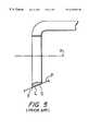
- Conventional cutting loopstypically employ a single flat lower surface. By flat is meant that a plane P would intersect the loop lower surface S in a line L. In other words, as viewed from the side (see FIG. 5 ), or in cross section the loop exhibits a flat lower surface S.
- a drawbackexists with this design in that a trailing edge E of the flat lower surface may increase irritation of the coagulated tissue.
- the object of the present inventionis to provide an electrode for a high-frequency instrument which vaporizes as well as cuts the tissue and with which surgery time is shortened and/or irritation of the coagulated tissue is reduced.
- the inventionrelates to high-frequency electrodes having a sharpened cutting edge which permits optimized current flow from the cutting edge into the tissue upon incision.
- the high current density occurring at the edgeleads to optimum incision into the tissue.
- the invented electrodesessentially has the general shape of a loop, it does not impede the surgeon's vision at the surgical site.
- An element of the present inventionis that it was recognized that it is possible to vaporize as well as cut with an electrode with reduced irritation to coagulated tissue, if the electrode is provided with a curved and/or multiple flat lower, i.e., approximately curved surface portions.
- curvedis meant that a plane P would intersect loop lower surface C in a point T somewhere on the surface (depending upon inclination of the plane) since the surface is a complex curved surface (see FIG. 1 ).
- the electrode as viewed from the side or in cross sectionexhibits a curved lower surface C.
- multiple flatis meant that a plane P would intersect loop lower surface M in two or more lines L depending upon inclination of the plane (see FIG. 6 A).
- the electrode as viewed from the side or in cross sectionexhibits a lower surface having two or more, and preferably having three or more flat surfaces M.
- the invented electrodespermit simultaneous “bloodless” cutting and vaporizing of the tissue with a reduction in the irritation which might occur due to a dragging of the known electrode's single flat lower surface's trailing edge E over the coagulated tissue (see FIG. 5 ).
- high-frequency currentflows into the tissue in a large surface and performs a coagulation and vaporization procedure during the cutting procedure. Nonetheless, it is still possible to “dig” respectively “excavate” to remove tissue with the invented electrode.
- the selective application of the lateral stirrups to join the loop and lead or leads of the electrodeprovides advantages particular to conventional thin loop electrodes, notably removing respectively cutting off “parasol” sections of tissue.
- stirrupsit is preferred if the stirrups do not comprise a wire material having a round cross section, but a band-shaped material respectively a material having an elliptical cross section, the longer axis of which extends in the direction of the longitudinal axis of the lead.
- the lead, the stirrups and the central sectionare arranged in a kind of “Z” configuration, facilitates cleaning the cut-off tissue from the invented electrodes.
- the preferred dimensions of the cutting loopare a radius ® of about 3 mm at an angle (A) of about 60°.
- the radius of curvature ® of the lower surfaceis preferably about 2.5 mm.
- the invented high-frequency electrodecan be fabricated in a known manner and, in particular, can be made of high temperature resistant materials, in particular titanium alloys.
- the top surface of the loopmay be insulated in such a manner that current only flows through the bottom surface and cutting edge of the loop, thereby confining the current flow for vaporization and coagulation to the required region and reducing the patient's current load.
- the electrode trailing edgemay also be insulated.
- FIG. 1a side cross sectional view of a cutting loop embodiment of the invention including a preferred curved lower surface
- FIG. 2is an end elevation view of the cutting loop electrode of FIG. 1,
- FIG. 3is a bottom plan view of the cutting loop electrode of FIG. 1,
- FIG. 4is an isometric view of the cutting loop electrode of FIG. 1,
- FIG. 5is a side cross section view of a prior art cutting loop electrode having a single flat lower surface
- FIG. 6is a side cross sectional view of a cutting loop embodiment of the invention including three lower flat surfaces and optional grooves on the lowermost flat surface,
- FIG. 7is an end elevation view of the cutting loop electrode of FIG. 6, and
- FIG. 8is a bottom plan view of the cutting loop electrode of FIG. 6 .
- FIG. 1 and 6are diagrams of embodiments of the invented high-frequency electrode.
- the electrodesare provided with a central section 1 , and in the FIG. 6 embodiment with two stirrups 2 ′ and 2 ′′ joining the central section with an outside insulated lead 3 , comprising two rods in the depicted embodiments. It is understood that a single rod may also be used.
- central section 1extends and connects to leads 3 , but stirrups may be used with this embodiment if desired.
- the high-frequency electrodeis connected via the outside insulated lead 3 , for example, to a standard resectoscope (not depicted), which is connected to a high-frequency generator, also not depicted.
- This high-frequency generatoris preferably a regulated generator. Instruments, such as those mass produced and sold by the applicant, Karl Storz GmbH & Co., Tuttlingen, Germany, can be used as resectoscopes and high-frequency generators.
- an embodiment of the invention illustrated in FIGS. 1-4includes a curved lower surface C.
- the surface, as illustrated in FIG. 1,sweeps upwardly away from cutting edge E of the electrode.
- the curvatureprovides ample coagulation while reducing irritation caused by the trailing edge.
- the dimensions of the preferred electrodeare a radius (R) of about 3 mm at an angle (A) of about 60°.
- the radius of curvature of the lower surfaceis about 2.5 mm.
- the remaining components of the FIG. 1 electrodeare substantially the same as and are described with respect to FIGS. 6-8.
- the illustrated high frequency electrodehas a lower surface comprised of three flat surfaces M.
- the prior art cutting loophas only a single flat lower surface, and accordingly, the trailing edge E of the electrode may adversely irritate tissue.
- the triple flat lower surfaces of this embodiment of the inventionapproximate the more preferred embodiment of the invention which includes a curved lower surface.
- the curved and approximately curved lower surface of a cutting loop electrodeprovide a high degree of coagulation and reduce irritation caused by a trailing edge of the known cutting loops illustrated in FIG. 5 and in U.S. Pat. No. 5,569,244.
- the central section 1 of the high-frequency electrodehas a longitudinal extension of about 0.6 to 1 mm for the loop of FIGS. 1-4, and about 2 mm to 6 mm, preferably 3 to 5 mm for the loop of FIGS. 6-8.
- the width of the central section 1is typically about 5 mm.
- the stirrupsare made of a wire material or a band-shaped material having a diameter respectively an extension in the direction of the longitudinal axis X of the lead 3 of typically 1 mm, permitting in certain cases to also cut through the tissue with one of the stirrups.
- the top side of the central sectionis provided with an insulation 4 and the bottom side may be provided with grooves as is illustrated in the FIG. 6 embodiment.
- insulation 4the current flow may be limited in that the current only enters the tissue from the bottom side but not from the top side of the central section.
- FIGS. 7 and 8show the particularly preferred dimensions of the FIG. 6 embodiment. FIGS. 7 and 8 are executed using the same scale so that the other dimensions can be drawn from the figures.
- the vaporization technique as well as the conventional cutting techniquecan be applied using the invented high-frequency electrode, thereby eliminating all the problems which can occur due to changing electrodes as required by the state of the art. Furthermore, the very high current flow, thus a current flow involving potential risk can be selectively employed only when it is really required. Simultaneous use of cutting and coagulation respectively vaporization methods makes the invented high-frequency electrode very efficient so that the narcosis times are distinctly shortened compare to other surgical methods.
Landscapes
- Health & Medical Sciences (AREA)
- Surgery (AREA)
- Engineering & Computer Science (AREA)
- Life Sciences & Earth Sciences (AREA)
- Biomedical Technology (AREA)
- Otolaryngology (AREA)
- Nuclear Medicine, Radiotherapy & Molecular Imaging (AREA)
- Plasma & Fusion (AREA)
- Physics & Mathematics (AREA)
- Heart & Thoracic Surgery (AREA)
- Medical Informatics (AREA)
- Molecular Biology (AREA)
- Animal Behavior & Ethology (AREA)
- General Health & Medical Sciences (AREA)
- Public Health (AREA)
- Veterinary Medicine (AREA)
- Surgical Instruments (AREA)
Abstract
Description
Claims (12)
Priority Applications (1)
| Application Number | Priority Date | Filing Date | Title |
|---|---|---|---|
| US09/320,316US6245069B1 (en) | 1995-12-22 | 1999-05-26 | Cutting loop electrode for high-frequency instrument |
Applications Claiming Priority (4)
| Application Number | Priority Date | Filing Date | Title |
|---|---|---|---|
| DE19548493 | 1995-12-22 | ||
| DE19548493ADE19548493A1 (en) | 1995-12-22 | 1995-12-22 | HF electrode for a monopolar working HF instrument |
| US09/091,119US6152921A (en) | 1995-12-22 | 1996-12-23 | High frequency (HF) electrode for a HF instrument operating in monopolar mode |
| US09/320,316US6245069B1 (en) | 1995-12-22 | 1999-05-26 | Cutting loop electrode for high-frequency instrument |
Related Parent Applications (1)
| Application Number | Title | Priority Date | Filing Date |
|---|---|---|---|
| US09/091,119Continuation-In-PartUS6152921A (en) | 1995-12-22 | 1996-12-23 | High frequency (HF) electrode for a HF instrument operating in monopolar mode |
Publications (1)
| Publication Number | Publication Date |
|---|---|
| US6245069B1true US6245069B1 (en) | 2001-06-12 |
Family
ID=26021652
Family Applications (1)
| Application Number | Title | Priority Date | Filing Date |
|---|---|---|---|
| US09/320,316Expired - LifetimeUS6245069B1 (en) | 1995-12-22 | 1999-05-26 | Cutting loop electrode for high-frequency instrument |
Country Status (1)
| Country | Link |
|---|---|
| US (1) | US6245069B1 (en) |
Cited By (22)
| Publication number | Priority date | Publication date | Assignee | Title |
|---|---|---|---|---|
| US6461357B1 (en)* | 1997-02-12 | 2002-10-08 | Oratec Interventions, Inc. | Electrode for electrosurgical ablation of tissue |
| US20040030330A1 (en)* | 2002-04-18 | 2004-02-12 | Brassell James L. | Electrosurgery systems |
| US20050245925A1 (en)* | 2003-01-31 | 2005-11-03 | Kobi Iki | Cartilage treatment probe |
| US6997941B2 (en) | 1996-08-13 | 2006-02-14 | Oratec Interventions, Inc. | Method and apparatus for treating annular fissures in intervertebral discs |
| US20070027450A1 (en)* | 2005-07-28 | 2007-02-01 | Forcept, Inc. | Devices and methods for mobilization of the uterus |
| US7951142B2 (en) | 2003-01-31 | 2011-05-31 | Smith & Nephew, Inc. | Cartilage treatment probe |
| US20120029512A1 (en)* | 2010-07-30 | 2012-02-02 | Willard Martin R | Balloon with surface electrodes and integral cooling for renal nerve ablation |
| US8419727B2 (en) | 2010-03-26 | 2013-04-16 | Aesculap Ag | Impedance mediated power delivery for electrosurgery |
| US8574229B2 (en) | 2006-05-02 | 2013-11-05 | Aesculap Ag | Surgical tool |
| US8696662B2 (en) | 2005-05-12 | 2014-04-15 | Aesculap Ag | Electrocautery method and apparatus |
| US8728072B2 (en) | 2005-05-12 | 2014-05-20 | Aesculap Ag | Electrocautery method and apparatus |
| CN103830003A (en)* | 2014-03-11 | 2014-06-04 | 青岛市城阳区人民医院 | Prostate resectoscope |
| US8827992B2 (en) | 2010-03-26 | 2014-09-09 | Aesculap Ag | Impedance mediated control of power delivery for electrosurgery |
| US8870867B2 (en) | 2008-02-06 | 2014-10-28 | Aesculap Ag | Articulable electrosurgical instrument with a stabilizable articulation actuator |
| US8888770B2 (en) | 2005-05-12 | 2014-11-18 | Aesculap Ag | Apparatus for tissue cauterization |
| US9113927B2 (en) | 2010-01-29 | 2015-08-25 | Covidien Lp | Apparatus and methods of use for treating blood vessels |
| US9173698B2 (en) | 2010-09-17 | 2015-11-03 | Aesculap Ag | Electrosurgical tissue sealing augmented with a seal-enhancing composition |
| US9339327B2 (en) | 2011-06-28 | 2016-05-17 | Aesculap Ag | Electrosurgical tissue dissecting device |
| US9339323B2 (en) | 2005-05-12 | 2016-05-17 | Aesculap Ag | Electrocautery method and apparatus |
| US9872724B2 (en) | 2012-09-26 | 2018-01-23 | Aesculap Ag | Apparatus for tissue cutting and sealing |
| US9918778B2 (en) | 2006-05-02 | 2018-03-20 | Aesculap Ag | Laparoscopic radiofrequency surgical device |
| WO2021042760A1 (en)* | 2019-09-05 | 2021-03-11 | 珠海市司迈科技有限公司 | Plough-shaped electrode for transurethral prostate surgery and usage method therefor |
Citations (8)
| Publication number | Priority date | Publication date | Assignee | Title |
|---|---|---|---|---|
| FR825301A (en) | 1936-11-12 | 1938-03-01 | Electric cautery | |
| DE2521719A1 (en) | 1975-05-15 | 1976-11-25 | Delma Elektro Med App | ELECTROSURGICAL DEVICE |
| DE29519844U1 (en) | 1995-12-15 | 1996-02-01 | Olympus Winter & Ibe Gmbh, 22045 Hamburg | Cutting electrode for resectoscopes |
| US5782829A (en)* | 1995-12-06 | 1998-07-21 | Northgate Technologies Incorporated | Resectoscope electrode assembly and methods of use |
| US5919190A (en)* | 1996-12-20 | 1999-07-06 | Vandusseldorp; Gregg A. | Cutting loop for an electrocautery probe |
| US5957923A (en)* | 1995-04-20 | 1999-09-28 | Symbiosis Corporation | Loop electrodes for electrocautery probes for use with a resectoscope |
| US6033400A (en)* | 1996-04-19 | 2000-03-07 | Circon Corporation | Shaped electrode for a resectoscope |
| US6080152A (en)* | 1998-06-05 | 2000-06-27 | Medical Scientific, Inc. | Electrosurgical instrument |
- 1999
- 1999-05-26USUS09/320,316patent/US6245069B1/ennot_activeExpired - Lifetime
Patent Citations (8)
| Publication number | Priority date | Publication date | Assignee | Title |
|---|---|---|---|---|
| FR825301A (en) | 1936-11-12 | 1938-03-01 | Electric cautery | |
| DE2521719A1 (en) | 1975-05-15 | 1976-11-25 | Delma Elektro Med App | ELECTROSURGICAL DEVICE |
| US5957923A (en)* | 1995-04-20 | 1999-09-28 | Symbiosis Corporation | Loop electrodes for electrocautery probes for use with a resectoscope |
| US5782829A (en)* | 1995-12-06 | 1998-07-21 | Northgate Technologies Incorporated | Resectoscope electrode assembly and methods of use |
| DE29519844U1 (en) | 1995-12-15 | 1996-02-01 | Olympus Winter & Ibe Gmbh, 22045 Hamburg | Cutting electrode for resectoscopes |
| US6033400A (en)* | 1996-04-19 | 2000-03-07 | Circon Corporation | Shaped electrode for a resectoscope |
| US5919190A (en)* | 1996-12-20 | 1999-07-06 | Vandusseldorp; Gregg A. | Cutting loop for an electrocautery probe |
| US6080152A (en)* | 1998-06-05 | 2000-06-27 | Medical Scientific, Inc. | Electrosurgical instrument |
Cited By (39)
| Publication number | Priority date | Publication date | Assignee | Title |
|---|---|---|---|---|
| US7647123B2 (en) | 1996-08-13 | 2010-01-12 | Oratec Interventions, Inc. | Method for treating intervertebral discs |
| US6997941B2 (en) | 1996-08-13 | 2006-02-14 | Oratec Interventions, Inc. | Method and apparatus for treating annular fissures in intervertebral discs |
| US8226697B2 (en) | 1996-08-13 | 2012-07-24 | Neurotherm, Inc. | Method for treating intervertebral disc |
| US7267683B2 (en) | 1996-08-13 | 2007-09-11 | Oratec Interventions, Inc. | Method for treating intervertebral discs |
| US7282061B2 (en) | 1996-08-13 | 2007-10-16 | Oratec Interventions, Inc. | Method of treating intervertebral disc |
| US7400930B2 (en) | 1996-08-13 | 2008-07-15 | Oratec Interventions, Inc. | Method for treating intervertebral discs |
| US8187312B2 (en) | 1996-08-13 | 2012-05-29 | Neurotherm, Inc. | Method for treating intervertebral disc |
| US6461357B1 (en)* | 1997-02-12 | 2002-10-08 | Oratec Interventions, Inc. | Electrode for electrosurgical ablation of tissue |
| US20040030330A1 (en)* | 2002-04-18 | 2004-02-12 | Brassell James L. | Electrosurgery systems |
| US7951142B2 (en) | 2003-01-31 | 2011-05-31 | Smith & Nephew, Inc. | Cartilage treatment probe |
| US8066700B2 (en) | 2003-01-31 | 2011-11-29 | Smith & Nephew, Inc. | Cartilage treatment probe |
| US8377058B2 (en) | 2003-01-31 | 2013-02-19 | Smith & Nephew, Inc. | Cartilage treatment probe |
| US8500734B2 (en) | 2003-01-31 | 2013-08-06 | Smith & Nephew, Inc. | Cartilage treatment probe |
| US20050245925A1 (en)* | 2003-01-31 | 2005-11-03 | Kobi Iki | Cartilage treatment probe |
| US8888770B2 (en) | 2005-05-12 | 2014-11-18 | Aesculap Ag | Apparatus for tissue cauterization |
| US10314642B2 (en) | 2005-05-12 | 2019-06-11 | Aesculap Ag | Electrocautery method and apparatus |
| US9339323B2 (en) | 2005-05-12 | 2016-05-17 | Aesculap Ag | Electrocautery method and apparatus |
| US8696662B2 (en) | 2005-05-12 | 2014-04-15 | Aesculap Ag | Electrocautery method and apparatus |
| US8728072B2 (en) | 2005-05-12 | 2014-05-20 | Aesculap Ag | Electrocautery method and apparatus |
| US7641651B2 (en) | 2005-07-28 | 2010-01-05 | Aragon Surgical, Inc. | Devices and methods for mobilization of the uterus |
| US20070027450A1 (en)* | 2005-07-28 | 2007-02-01 | Forcept, Inc. | Devices and methods for mobilization of the uterus |
| US8574229B2 (en) | 2006-05-02 | 2013-11-05 | Aesculap Ag | Surgical tool |
| US9918778B2 (en) | 2006-05-02 | 2018-03-20 | Aesculap Ag | Laparoscopic radiofrequency surgical device |
| US11058478B2 (en) | 2006-05-02 | 2021-07-13 | Aesculap Ag | Laparoscopic radiofrequency surgical device |
| US8870867B2 (en) | 2008-02-06 | 2014-10-28 | Aesculap Ag | Articulable electrosurgical instrument with a stabilizable articulation actuator |
| US9113927B2 (en) | 2010-01-29 | 2015-08-25 | Covidien Lp | Apparatus and methods of use for treating blood vessels |
| US9888962B2 (en) | 2010-01-29 | 2018-02-13 | Covidien Lp | Apparatus and method of use for treating blood vessels |
| US8827992B2 (en) | 2010-03-26 | 2014-09-09 | Aesculap Ag | Impedance mediated control of power delivery for electrosurgery |
| US9277962B2 (en) | 2010-03-26 | 2016-03-08 | Aesculap Ag | Impedance mediated control of power delivery for electrosurgery |
| US8419727B2 (en) | 2010-03-26 | 2013-04-16 | Aesculap Ag | Impedance mediated power delivery for electrosurgery |
| US10130411B2 (en) | 2010-03-26 | 2018-11-20 | Aesculap Ag | Impedance mediated control of power delivery for electrosurgery |
| US20120029512A1 (en)* | 2010-07-30 | 2012-02-02 | Willard Martin R | Balloon with surface electrodes and integral cooling for renal nerve ablation |
| US9173698B2 (en) | 2010-09-17 | 2015-11-03 | Aesculap Ag | Electrosurgical tissue sealing augmented with a seal-enhancing composition |
| US10004555B2 (en) | 2011-06-28 | 2018-06-26 | Aesculap Ag | Electrosurgical tissue dissecting device |
| US9339327B2 (en) | 2011-06-28 | 2016-05-17 | Aesculap Ag | Electrosurgical tissue dissecting device |
| US9872724B2 (en) | 2012-09-26 | 2018-01-23 | Aesculap Ag | Apparatus for tissue cutting and sealing |
| CN103830003A (en)* | 2014-03-11 | 2014-06-04 | 青岛市城阳区人民医院 | Prostate resectoscope |
| WO2021042760A1 (en)* | 2019-09-05 | 2021-03-11 | 珠海市司迈科技有限公司 | Plough-shaped electrode for transurethral prostate surgery and usage method therefor |
| US20210068884A1 (en)* | 2019-09-05 | 2021-03-11 | Simai Co., Ltd. | Electrode for prostate surgery and using method thereof |
Similar Documents
| Publication | Publication Date | Title |
|---|---|---|
| US6245069B1 (en) | Cutting loop electrode for high-frequency instrument | |
| US5919190A (en) | Cutting loop for an electrocautery probe | |
| US5571101A (en) | Electrosurgical electrode for DCR surgical procedure | |
| US6572614B1 (en) | Bipolar arthroscopic probe | |
| US6030383A (en) | Electrosurgical instrument and method of use | |
| KR100322052B1 (en) | Electric field concentrated electrosurgical electrode | |
| US6197025B1 (en) | Grooved slider electrode for a resectoscope | |
| US6406476B1 (en) | Bipolar, fluid assisted coagulator/ablator probe for arthroscopy | |
| US6461357B1 (en) | Electrode for electrosurgical ablation of tissue | |
| EP0742696B1 (en) | Electrosurgical excisor for uterine cervix | |
| US6757565B2 (en) | Electrosurgical instrument having a predetermined heat profile | |
| US5582610A (en) | Grooved slider electrode for a resectoscope | |
| US6395001B1 (en) | Electrosurgical electrode for wedge resection | |
| US5913864A (en) | Electrosurgical dermatological curet | |
| US5749870A (en) | Electrode for coagulation and resection | |
| US20030109876A1 (en) | Instrument for high-frequency treatment and method of high-frequency treatment | |
| US6033400A (en) | Shaped electrode for a resectoscope | |
| EP1095627A1 (en) | Electrosurgical probe for surface treatment | |
| US5766215A (en) | Electrosurgical loop providing enhanced tissue coagulation | |
| CA2074431A1 (en) | Pivoting multiple loop bipolar cutting device | |
| US5669906A (en) | Grooved roller electrode for a resectoscope | |
| CA2280696C (en) | Electric field concentrated electrosurgical electrode | |
| US6152921A (en) | High frequency (HF) electrode for a HF instrument operating in monopolar mode | |
| US20020161363A1 (en) | Rotational guided electrosurgical electrode loop (GREEL) | |
| WO1998016162A1 (en) | Hook/spatula electrosurgery device and methods of forming and of using the same for tissue dissection |
Legal Events
| Date | Code | Title | Description |
|---|---|---|---|
| AS | Assignment | Owner name:KARL STORZ GMBH & CO., GERMANY Free format text:ASSIGNMENT OF ASSIGNORS INTEREST;ASSIGNOR:GMINDER, FRANK;REEL/FRAME:010014/0725 Effective date:19990507 | |
| STCF | Information on status: patent grant | Free format text:PATENTED CASE | |
| AS | Assignment | Owner name:KARL STORZ GMBH & CO. KG, GERMANY Free format text:CHANGE OF NAME;ASSIGNOR:KARL STORZ GMBH & CO.;REEL/FRAME:011850/0660 Effective date:19991008 | |
| AS | Assignment | Owner name:KARL STORZ GMBH & CO. KG, GERMANY Free format text:CORRECTIVE TO REMOVE A SERIAL NUMBER PREVIOUSLY RECORDED AT REEL 011850 FRAME 0660. (CHANGE OF NAME;ASSIGNOR:KARL STORZ GMBH & CO.;REEL/FRAME:013656/0227 Effective date:19991008 | |
| FPAY | Fee payment | Year of fee payment:4 | |
| FEPP | Fee payment procedure | Free format text:PAYOR NUMBER ASSIGNED (ORIGINAL EVENT CODE: ASPN); ENTITY STATUS OF PATENT OWNER: LARGE ENTITY | |
| FPAY | Fee payment | Year of fee payment:8 | |
| FPAY | Fee payment | Year of fee payment:12 | |
| AS | Assignment | Owner name:KARL STORZ SE & CO. KG, GERMANY Free format text:CHANGE OF NAME;ASSIGNOR:KARL STORZ GMBH & CO. KG;REEL/FRAME:045373/0627 Effective date:20170911 |