US6244544B1 - Method and apparatus for holding a capacitor without separable fasteners - Google Patents
Method and apparatus for holding a capacitor without separable fastenersDownload PDFInfo
- Publication number
- US6244544B1 US6244544B1US09/253,199US25319999AUS6244544B1US 6244544 B1US6244544 B1US 6244544B1US 25319999 AUS25319999 AUS 25319999AUS 6244544 B1US6244544 B1US 6244544B1
- Authority
- US
- United States
- Prior art keywords
- cover
- capacitor
- panel
- opening
- holder
- Prior art date
- Legal status (The legal status is an assumption and is not a legal conclusion. Google has not performed a legal analysis and makes no representation as to the accuracy of the status listed.)
- Expired - Fee Related
Links
Images


Classifications
- H—ELECTRICITY
- H01—ELECTRIC ELEMENTS
- H01G—CAPACITORS; CAPACITORS, RECTIFIERS, DETECTORS, SWITCHING DEVICES, LIGHT-SENSITIVE OR TEMPERATURE-SENSITIVE DEVICES OF THE ELECTROLYTIC TYPE
- H01G2/00—Details of capacitors not covered by a single one of groups H01G4/00-H01G11/00
- H01G2/02—Mountings
- H01G2/04—Mountings specially adapted for mounting on a chassis
Definitions
- the present inventionrelates generally to mounting brackets. More particularly it relates to a mounting structure used to mount capacitors used in motor drives.
- Present mounting systemsgenerally consist of sheet metal clamps that grip around the body of the capacitor and bolt to an assembly panel with the use of threaded fasteners.
- U.S. Pat. No. 4,712,162discusses the requirement for a variety of clamping brackets to mount capacitors of varying sizes into electronic controls or fixtures.
- Quioguediscloses a hold-down strap to compensate for the variety of clamping bracket sizes and designs used.
- the hold-down strapuses screw and nut fasteners, as do most clamping brackets.
- U.S. Pat. No. 4,937,718discloses a mounting bracket for receiving and mounting the capacitor to a support surface with screw and nut fasteners.
- the mounting bracket in Murrayhas a deformable plane intersecting a second deformable plane.
- the first plane sectionis secured to the support surface to exert a downward spring force upon the second plane or surface.
- the second planehas a central opening for physically engaging the capacitor at an angle.
- Each bracketgenerally has at least two threaded fasteners.
- each threaded fastenertypically has a minimum of two pieces, the nut, and the bolt; generally a locking washer of some type is required.
- the time and cost to assemble a unitincreases geometrically with the number of capacitors.
- the deviceshould have the capability to align the capacitor terminals in a desired orientation.
- This inventionrelates to a capacitor holder for mounting a capacitor used in motor drives and electronic fixtures.
- This inventionis of particular use for mounting a capacitor used with a motor drive or electronic assembly into a panel support, typically a sheet metal panel. Specifically, it accomplishes the mounting of the capacitor without the use of separable fasteners, thus saving assembly time and manufacturing costs.
- An embodiment of the inventionconsists of an injection molded plastic cover that is installed over the top of the capacitor. A metal clip is then pressed over the bottom of the capacitor and snapped into the plastic cover to form an assembly including the capacitor holder and the capacitor. Once assembled, the capacitor holder is installed into the panel.
- the installation procedurepreferably, consists of either a push-in and twist or a push-in and snap-fit procedure, depending on the model of capacitor holder being used.
- Both the push-in and twist and snap-fit proceduresare adapted to accommodate a plurality of panel opening thicknesses.
- An object of this inventionis to provide a mounting device for a DC bus capacitor.
- Another object of this inventionis to provide a capacitor holder for motor drives which does not require separable fasteners to mount the capacitor in a fixture panel.
- Another object of this inventionis to provide a capacitor holder which aligns capacitor terminals in a desired orientation in the fixture panel.
- a further object of the inventionis to provide a capacitor holder which reduce the time to assemble to the fixture, and thus saves manufacturing costs.
- Another object of this inventionis to provide a device which reduces the likelihood of explosion due to improper capacitor orientation.
- Yet another objectis to provide a capacitor holder which guarantees a polarity match.
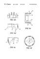
- FIGS. 1 a and 1 bshow a prior art clamp bracket requiring screw and nut fasteners.
- FIGS. 2 a and 2 bshow a other embodiment of a clamp bracket requiring screw and nut fasteners.
- FIG. 3shows an exploded view of the invention.
- FIG. 4shows the invention assembled and installed into a sheet metal panel.
- FIG. 5shows a perspective view of a support clip.
- FIG. 5 ashows a plan view of the support clip shown in FIG. 5 .
- FIG. 5 bshows a side view of the support clip shown in FIG. 5 .
- FIG. 6shows a perspective view of a cover which uses a push-in and snap-fit locking member to mount the capacitor in a panel.
- FIG. 6 ashows a plan view of the cover shown in FIG. 6 .
- FIG. 6 bshows a side view of the cover shown in FIG. 6 .
- FIG. 6 cshows a section view of the cover shown in FIG. 6 a cut along section line AA.
- FIG. 6 dshows a section view of the cover shown in FIG. 6 a cut along section line BB.
- FIG. 6 eshows a section view of the cover shown in FIG. 6 a cut along section line CC.
- FIG. 6 fshows a bottom view of the cover shown in FIG. 6 .
- FIG. 7shows a perspective view of a cover which uses a push-in and twist-locking member to mount the capacitor in a panel.
- FIG. 7a top view of the cover shown in FIG. 7 .
- FIG. 7 bshows a side view of the cover shown in FIG. 7 .
- FIG. 7 cshows a section view of the cover shown in FIG. 7 a cut along section line AA.
- FIG. 7 dshows a section view of the cover shown in FIG. 7 a cut along section line BB.
- FIG. 7 eshows a bottom view of the cover shown in FIG. 7 .
- FIG. 7 fshows a side view of the cover shown in FIG. 7 including support attachment shoulders.
- FIGS. 1 a and 1 bshow a prior art clamp bracket used to mount capacitors in a panel.
- the clamp bracketrequires screw and nut fasteners.
- FIGS. 2 a and 2 bshow a similar clamp mounting bracket using more screw and nut fasteners than the mounting bracket shown in FIGS. 1 a and 1 b . Due to the multiplicity of fasteners required to mount a single capacitor, the assembling time increases dramatically as the number of capacitors to be installed in an electronic assembly increase.
- FIG. 3shows an exploded view of the invention, a capacitor holder 5 , prior to installation in a panel P having a panel opening O for receiving a capacitor C.
- the capacitor Cincludes a capacitor top and a capacitor bottom. Terminals T extend upward from the capacitor top and a capacitor venting cap V is defined within the capacitor top.
- the capacitor holder 5includes a support 10 and a cover 30 .
- the support 10 shown in FIG. 3is a U-shaped bracket having upright ends 12 .
- the upright ends 12can easily be varied to accommodate different lengths of capacitors from different vendors.
- the upright ends 12include slots 14 adapted to snap-fit mate with the cover 30 .
- Cover 30as shown in FIG. 3, includes mount attachments 34 , and a top surface 36 , the top surface 36 defines an opening 38 .
- the cover top surface 36also defines a venting cap cutout 42 . This is best seen if FIG. 6 a .
- the venting cap cutout 42 and the cover opening 38form a unitary opening.
- the opening 38receives the capacitor terminals T and aligns the capacitor C relative to the cover 30 . This is the configuration shown in FIG. 6 a .
- Other conventional designswill be apparent to those skilled in the art.
- the mount attachments 34as shown in FIG. 3, include integral push-in and twist members 37 .
- FIG. 7 bAnother push-in twist embodiment is shown in FIG. 7 b .
- a lower rim 52depends from a cover top surface 36 .
- the tabs 33 extending from the cover top surface 36include a first shoulder 56 opening in a first direction and a second shoulder 58 opening in a second direction opposite to the first direction.
- the first shoulder 56 and the second shoulder 58are in spaced relation to the lower cover rim 52 such that the tabs 33 may be pushed in to a panel opening O whereby the lower cover rim 52 rests on the panel P and the cover 30 may then be twisted clockwise to accommodate a first panel thickness H or twisted counter-clockwise to mate with a second panel thickness L.
- the tabs 33 in this embodimentdo double duty as cover support attachments and mount attachments.
- the push-in and twist members 37 shown in FIGS. 7 and 7 balso include a locking member 47 which prevents the cover 30 from rotating too far in the panel opening O.
- Push-in and twist members 37are used to mount the capacitor C in the panel opening O.
- the opening 38is used to align the capacitor terminals T in relation to the cover 30 .
- the venting cap cutout 42is also used to visually align the cover with the capacitor.
- a conforming feature 41shown in FIG. 6 f , used to allow capacitor venting, in the case where the capacitor is not assembled properly.
- the cover 30 shown in FIG. 3includes tabs 33 extending from the cover 30 adapted to snap-fit mate with the U-shaped brackets 10 .
- the capacitor holder 5aligns the capacitor C in a desired alignment in the panel P.
- FIG. 4shows the capacitor holder 5 assembled and mounted in the panel P. Capacitor terminals T are shown projecting through the opening 38 in the top surface 36 of the cover 30 .
- FIG. 5shows a perspective view of a U-shaped bracket support 10 for supporting the capacitor C and mating with the cover 30 .
- the U-shaped bracket 10 depictedincludes upright ends 12 .
- the upright endsinclude slots 14 for attaching the support 10 to the cover 30 .
- FIGS. 5 a and 5 bshow a front and side view of the U-shaped bracket, respectively.
- FIG. 6shows a cover 30 for covering the capacitor C.
- Tabs 33extend from the cover 30 to attach to a capacitor holder support 10 .
- the model of capacitor holder shown in FIG. 6uses snap-fit attachments.
- the cover 30 shownincludes a plurality of mount attachments 34 , the mount attachments 34 including snap-fit tabs 35 for snap-fit mounting the capacitor C into the panel P and aligning the cover 30 in a proper orientation in the panel P.
- the snap-fit tabs 35are also referred to as snap-fit members 35 .
- the cover 30includes snap-fit members 35 adapted to mate with a panel having a first thickness H and snap-fit members 39 adapted to fit with a panel having a second thickness L.
- the snap-fit members 35 and 39are adapted to mate with 14 and 16 gage sheet metal panels respectively, in one embodiment.
- the cover 30includes a top surface 36 and an opening 38 defined in the top surface 36 to align the capacitor C with respect to the cover 30 .
- a pair of cover support attachments 32depending from the cover 30 top surface 36 .
- the pair of cover support attachments 32include tabs 33 adapted to mate with the support 10 upright 12 .
- the tabs 33include snap-fit elements 31 adapted to mate with the upright support element 12 and slot 14 .
- FIG. 6 ais a top view of the cover shown in FIG. 6 showing section lines AA, BB, and CC.
- FIG. 6 aalso shows two pair the location of a plurality of mount attachments.
- the plurality of mount attachmentsinclude two pair of snap-fit members 39 and 35 respectively.
- the snap-fit members 39 and 35allow the cap cover to engage, or mate with, a first and second thickness of sheet metal panel H, and L. Venting cap cutout 42 is also depicted.
- FIG. 6 bis a side view of the cover shown in FIG. 6 .
- FIG. 6 cshows a section view of the cover 30 cut along section line AA.
- FIG. 6 dshows a section view cut along section line BB.
- FIG. 6 eshows a section view cut along section line CC.
- FIG. 6 fshows a bottom view of the cover 30 shown in FIG. 6 . It shows a conforming feature 41 used to allow capacitor venting, in the case where the capacitor is not assembled properly.
- the featureshave typically any conventional set of complementary or conforming bumps, impressions, and the like.
- FIG. 7shows a perspective view of another embodiment of the cover 30 .
- the cover 30 shown in FIG. 7uses push-in and twist members 37 to mount the capacitor C in the panel P.
- the push-in and twist members 37run along the periphery of cover 30 in this embodiment.
- a lower rim 52extends from the cover top surface 36 .
- a first shoulder or attachment support shoulder 56is in space relation to the lower rim 52 such that a panel opening having a first thickness may be mated with the first support attachment shoulder 56 .
- the first attachment shoulder 56opens outward in a first direction.
- a second attachment shoulder 58opens outward in a second direction opposite from the first direction.
- the second support attachment shoulder 58is also in fixed space relation to the lower rim 52 .
- the capacitormay be inserted into a panel opening O and the cover 30 rotated clockwise to engage one panel opening thickness, and rotated counter-clockwise to engage another panel opening thickness.
- the mounting attachments and the cover support attachmentsare integral with the cover.
- the cover 30includes a top surface 36 defining an opening 38 for aligning the capacitor C.
- FIG. 7 ais a plan view of the cover 30 and showing section lines AA and BB.
- FIG. 7 bis a side view of the cover 30 shown in FIG. 7 .
- FIG. 7 cis a section view of the cover 30 shown in FIG. 7 a cut along section line AA.
- FIG. 7 cshows a snap-fit attachment member 33 more clearly. Also seen more clearly is the snap-fit element 31 which is included in the snap-fit attachment number 33 . Snap-fit elements 31 are also referred as tab snap-fit elements 31 because snap-fit attachment 33 is also referred to as a tab snap-fit member 33 .
- the snap-fit attachment member 33is used to attach the cover 30 to the support 10 .
- FIG. 7 dshows a section view of the cover 30 in FIG. 7 a cut along section line BB.
- FIG. 7 eshows a bottom view of the cover 30 shown in FIG. 7 .
- the cover 30is formed using a plastic injection molding process, and the cover support attachment members 32 are snap-fit tabs 33 depending from the cover 30 .
- the mounting members 34are either a push-in and twist 37 or a push-in and snap-fit 35 configuration.
- the support 10is a U-shaped bracket, preferably of stainless steel.
- the U-shaped brackethas upright ends 12 which include snap-fit support attachments 14 adapted to mate with cover support attachment snap-fit tabs 33 .
Landscapes
- Engineering & Computer Science (AREA)
- Power Engineering (AREA)
- Microelectronics & Electronic Packaging (AREA)
- Mounting Components In General For Electric Apparatus (AREA)
Abstract
Description
Claims (23)
Priority Applications (1)
| Application Number | Priority Date | Filing Date | Title |
|---|---|---|---|
| US09/253,199US6244544B1 (en) | 1999-02-19 | 1999-02-19 | Method and apparatus for holding a capacitor without separable fasteners |
Applications Claiming Priority (1)
| Application Number | Priority Date | Filing Date | Title |
|---|---|---|---|
| US09/253,199US6244544B1 (en) | 1999-02-19 | 1999-02-19 | Method and apparatus for holding a capacitor without separable fasteners |
Publications (1)
| Publication Number | Publication Date |
|---|---|
| US6244544B1true US6244544B1 (en) | 2001-06-12 |
Family
ID=22959295
Family Applications (1)
| Application Number | Title | Priority Date | Filing Date |
|---|---|---|---|
| US09/253,199Expired - Fee RelatedUS6244544B1 (en) | 1999-02-19 | 1999-02-19 | Method and apparatus for holding a capacitor without separable fasteners |
Country Status (1)
| Country | Link |
|---|---|
| US (1) | US6244544B1 (en) |
Cited By (9)
| Publication number | Priority date | Publication date | Assignee | Title |
|---|---|---|---|---|
| EP1742236A1 (en)* | 2005-07-08 | 2007-01-10 | MGE UPS Systems (S.A.) | Holding device for support of capacitors and support provided with such a device |
| DE102008048082A1 (en)* | 2008-09-19 | 2010-04-08 | Bombardier Transportation Gmbh | Arrangement and method for holding a plurality of electrical capacitor assemblies |
| US20130140417A1 (en)* | 2011-12-02 | 2013-06-06 | Sensata Technologies, Inc. | Thermal switch mounting clip |
| US8629349B2 (en) | 2010-07-30 | 2014-01-14 | Hubbell Incorporated | Electrical assembly and adapter for wiring device |
| CN105023749A (en)* | 2015-07-24 | 2015-11-04 | 许继电气股份有限公司 | Capacitor hoop |
| CN105023748A (en)* | 2015-06-29 | 2015-11-04 | 南通新三能电子有限公司 | Bolt capacitor installation device |
| WO2017178507A1 (en)* | 2016-04-15 | 2017-10-19 | Danfoss Power Electronics A/S | Capacitor cup and arrangement for fastening capacitor cup |
| US10029186B2 (en) | 2016-07-11 | 2018-07-24 | Michael Miller | Bobble for bottle neck |
| CN108878138A (en)* | 2018-06-20 | 2018-11-23 | 马婷婷 | A kind of universal protected against explosion capacitor retainer |
Citations (19)
| Publication number | Priority date | Publication date | Assignee | Title |
|---|---|---|---|---|
| US1398373A (en)* | 1920-04-02 | 1921-11-29 | Manning Maxwell & Moore Inc | Retaining device for gage-cases |
| US2627359A (en)* | 1949-05-26 | 1953-02-03 | United Carr Fastener Corp | Housing for electric switches and the like |
| US3511982A (en)* | 1966-04-18 | 1970-05-12 | Rival Lamps Ltd | Lamp holders |
| US4198671A (en) | 1978-06-05 | 1980-04-15 | Donigan Carolyn L | Capacitor assembly |
| GB2046534A (en)* | 1979-12-13 | 1980-11-12 | Alps Electric Co Ltd | Method of mounting an electrical component on a substrate |
| US4356987A (en) | 1980-04-28 | 1982-11-02 | Patentverwertungs-Und Finanzierungsgesellschaft Serania Ag | Support clip for electrical conductors or tubes |
| US4360848A (en) | 1980-06-18 | 1982-11-23 | Noutko Theodore E | Capacitor protective device |
| US4390219A (en)* | 1981-03-16 | 1983-06-28 | Heil-Quaker Corporation | Terminal block and capacitor mount for blower |
| US4414615A (en) | 1980-09-18 | 1983-11-08 | U.S. Philips Corporation | Mounting structure for a high pressure sodium lamp |
| US4712162A (en) | 1986-12-04 | 1987-12-08 | Hubbell Incorporated | Capacitor hold-down strap |
| US4791539A (en) | 1983-09-16 | 1988-12-13 | Manville Corporation | Luminaire having quick-disconnect electrical components |
| US4937718A (en) | 1988-12-12 | 1990-06-26 | General Electric Company | Discharge lamp luminaire |
| JPH0410607A (en)* | 1990-04-27 | 1992-01-14 | Fuji Electric Co Ltd | Capacitor mounting device |
| JPH0689832A (en)* | 1992-09-07 | 1994-03-29 | Nippon Chemicon Corp | Fixing device for electrolytic capacitor |
| US5314149A (en) | 1991-05-24 | 1994-05-24 | Channel Products, Inc. | Snap-in mount for housing within panel |
| US5420748A (en) | 1993-03-31 | 1995-05-30 | Samsung Electro-Mechanics Co., Ltd. | Surface mounting type chip capacitor |
| JPH07283068A (en)* | 1994-04-08 | 1995-10-27 | Nichicon Corp | Holder for securing capacitor |
| US5493158A (en) | 1993-10-04 | 1996-02-20 | Emerson Electric Co. | Motor capacitor bracket |
| US5750935A (en)* | 1996-05-16 | 1998-05-12 | Lucent Technologies Inc. | Mounting device for attaching a component through an aperture in a circuit board |
- 1999
- 1999-02-19USUS09/253,199patent/US6244544B1/ennot_activeExpired - Fee Related
Patent Citations (19)
| Publication number | Priority date | Publication date | Assignee | Title |
|---|---|---|---|---|
| US1398373A (en)* | 1920-04-02 | 1921-11-29 | Manning Maxwell & Moore Inc | Retaining device for gage-cases |
| US2627359A (en)* | 1949-05-26 | 1953-02-03 | United Carr Fastener Corp | Housing for electric switches and the like |
| US3511982A (en)* | 1966-04-18 | 1970-05-12 | Rival Lamps Ltd | Lamp holders |
| US4198671A (en) | 1978-06-05 | 1980-04-15 | Donigan Carolyn L | Capacitor assembly |
| GB2046534A (en)* | 1979-12-13 | 1980-11-12 | Alps Electric Co Ltd | Method of mounting an electrical component on a substrate |
| US4356987A (en) | 1980-04-28 | 1982-11-02 | Patentverwertungs-Und Finanzierungsgesellschaft Serania Ag | Support clip for electrical conductors or tubes |
| US4360848A (en) | 1980-06-18 | 1982-11-23 | Noutko Theodore E | Capacitor protective device |
| US4414615A (en) | 1980-09-18 | 1983-11-08 | U.S. Philips Corporation | Mounting structure for a high pressure sodium lamp |
| US4390219A (en)* | 1981-03-16 | 1983-06-28 | Heil-Quaker Corporation | Terminal block and capacitor mount for blower |
| US4791539A (en) | 1983-09-16 | 1988-12-13 | Manville Corporation | Luminaire having quick-disconnect electrical components |
| US4712162A (en) | 1986-12-04 | 1987-12-08 | Hubbell Incorporated | Capacitor hold-down strap |
| US4937718A (en) | 1988-12-12 | 1990-06-26 | General Electric Company | Discharge lamp luminaire |
| JPH0410607A (en)* | 1990-04-27 | 1992-01-14 | Fuji Electric Co Ltd | Capacitor mounting device |
| US5314149A (en) | 1991-05-24 | 1994-05-24 | Channel Products, Inc. | Snap-in mount for housing within panel |
| JPH0689832A (en)* | 1992-09-07 | 1994-03-29 | Nippon Chemicon Corp | Fixing device for electrolytic capacitor |
| US5420748A (en) | 1993-03-31 | 1995-05-30 | Samsung Electro-Mechanics Co., Ltd. | Surface mounting type chip capacitor |
| US5493158A (en) | 1993-10-04 | 1996-02-20 | Emerson Electric Co. | Motor capacitor bracket |
| JPH07283068A (en)* | 1994-04-08 | 1995-10-27 | Nichicon Corp | Holder for securing capacitor |
| US5750935A (en)* | 1996-05-16 | 1998-05-12 | Lucent Technologies Inc. | Mounting device for attaching a component through an aperture in a circuit board |
Cited By (20)
| Publication number | Priority date | Publication date | Assignee | Title |
|---|---|---|---|---|
| FR2888393A1 (en)* | 2005-07-08 | 2007-01-12 | Mge Ups Systems Sa Sa | HOLDING DEVICE FOR SUPPORTING CAPACITORS AND SUPPORT COMPRISING SUCH A DEVICE |
| EP1742236A1 (en)* | 2005-07-08 | 2007-01-10 | MGE UPS Systems (S.A.) | Holding device for support of capacitors and support provided with such a device |
| DE102008048082A1 (en)* | 2008-09-19 | 2010-04-08 | Bombardier Transportation Gmbh | Arrangement and method for holding a plurality of electrical capacitor assemblies |
| US20110222261A1 (en)* | 2008-09-19 | 2011-09-15 | Bombardier Transportation Gmbh | Arrangement and method for holding a plurality of electric capacitor assemblies |
| JP2012503283A (en)* | 2008-09-19 | 2012-02-02 | ボンバルディール・トランスポーテイション・ゲゼルシヤフト・ミット・ベシュレンクテル・ハフツング | Apparatus and method for holding multiple capacitor assemblies |
| US8654545B2 (en)* | 2008-09-19 | 2014-02-18 | Bombardier Transportation Gmbh | Arrangement and method for holding a plurality of electric capacitor assemblies |
| US8629349B2 (en) | 2010-07-30 | 2014-01-14 | Hubbell Incorporated | Electrical assembly and adapter for wiring device |
| US20130140417A1 (en)* | 2011-12-02 | 2013-06-06 | Sensata Technologies, Inc. | Thermal switch mounting clip |
| CN105023748B (en)* | 2015-06-29 | 2018-08-21 | 南通新三能电子有限公司 | A kind of bolt capacitor mounting device |
| CN105023748A (en)* | 2015-06-29 | 2015-11-04 | 南通新三能电子有限公司 | Bolt capacitor installation device |
| CN105023749A (en)* | 2015-07-24 | 2015-11-04 | 许继电气股份有限公司 | Capacitor hoop |
| CN105023749B (en)* | 2015-07-24 | 2018-01-23 | 许继电气股份有限公司 | A kind of capacitor clamp |
| WO2017178507A1 (en)* | 2016-04-15 | 2017-10-19 | Danfoss Power Electronics A/S | Capacitor cup and arrangement for fastening capacitor cup |
| CN108780698A (en)* | 2016-04-15 | 2018-11-09 | 丹佛斯电力电子有限公司 | Capacitor cup and arrangement for fastening capacitor cup |
| CN108780698B (en)* | 2016-04-15 | 2020-09-08 | 丹佛斯电力电子有限公司 | Capacitor cup and device for fastening capacitor cup |
| US10886064B2 (en) | 2016-04-15 | 2021-01-05 | Danfoss Power Electronics A/S | Capacitor cup and arrangement for fastening capacitor cup |
| US10029186B2 (en) | 2016-07-11 | 2018-07-24 | Michael Miller | Bobble for bottle neck |
| US10967287B2 (en) | 2016-07-11 | 2021-04-06 | Michael Miller | Bobble for bottle neck |
| CN108878138A (en)* | 2018-06-20 | 2018-11-23 | 马婷婷 | A kind of universal protected against explosion capacitor retainer |
| CN108878138B (en)* | 2018-06-20 | 2021-03-12 | 盐城星晨科技有限公司 | General explosion-proof formula electric capacity holder |
Similar Documents
| Publication | Publication Date | Title |
|---|---|---|
| US6669155B2 (en) | Mounting device | |
| US6244544B1 (en) | Method and apparatus for holding a capacitor without separable fasteners | |
| EP0808251B1 (en) | Snap-in visor mount and electrical connectors for visor mounts | |
| US7108238B2 (en) | Outdoor light mounting bracket | |
| US5399839A (en) | Device for holding a built-in cooking apparatus | |
| US5951223A (en) | Self-retaining snap-in clip | |
| US5057649A (en) | Electrical wiring box | |
| US20090074534A1 (en) | Supporting apparatus for electrical apparatus | |
| JPH05187426A (en) | Nut plate retainer | |
| US20050006557A1 (en) | Collar screw or collar nut housing attachment | |
| US6283619B1 (en) | Lighting fixture assembly having locking arm components | |
| US20070046054A1 (en) | Interior trim accessory attachment apparatus | |
| US5160277A (en) | Snap-in lamp for printed circuits | |
| US5753859A (en) | Fitting structure for electrical connection box | |
| KR19980024834A (en) | Gas bag module fixture | |
| US6889414B2 (en) | Reusable retainer and assembly | |
| US4888572A (en) | Apparatus for relieving strain on electrical lead | |
| US20250125601A1 (en) | Power distribution box having a bracket | |
| JPS5843261Y2 (en) | Back cover mounting device | |
| JPH0738536Y2 (en) | Haze plate mounting bracket | |
| KR0132937Y1 (en) | Battery terminal structure for cars | |
| WO2021091547A1 (en) | Computing device stands and display mount interface spacers | |
| JPH0534143Y2 (en) | ||
| JPS5918715Y2 (en) | Connector mounting device | |
| JPS6334177Y2 (en) |
Legal Events
| Date | Code | Title | Description |
|---|---|---|---|
| AS | Assignment | Owner name:MAGNETEK, INC., CALIFORNIA Free format text:ASSIGNMENT OF ASSIGNORS INTEREST;ASSIGNORS:KITSCHA, JOHN;POMES, JIM;REEL/FRAME:011606/0498 Effective date:19990218 | |
| AS | Assignment | Owner name:BANK ONE, NA, OHIO Free format text:SECURITY AGREEMENT;ASSIGNOR:MAGNETEK, INC.;REEL/FRAME:014455/0201 Effective date:20030815 | |
| FPAY | Fee payment | Year of fee payment:4 | |
| AS | Assignment | Owner name:ABLECO FINANCE LLC, NEW YORK Free format text:SECURITY AGREEMENT;ASSIGNORS:MAGNETEK, INC.;MAGNETEK ADS POWER, INC.;MAGNETEK MONDEL HOLDING, INC.;AND OTHERS;REEL/FRAME:016621/0221 Effective date:20050930 | |
| AS | Assignment | Owner name:MAGNETEK, INC., A DELAWARE CORPORATION, CALIFORNIA Free format text:TERMINATION AND RELEASE OF SECURITY INTEREST;ASSIGNOR:JPMORGAN CHASE BANK, N.A., A NATIONAL BANKING ASSOCIATION;REEL/FRAME:016621/0801 Effective date:20051003 | |
| AS | Assignment | Owner name:WELLS FARGO FOOTHILL, INC., AS AGENT, A CALIFORNIA Free format text:SECURITY AGREEMENT;ASSIGNOR:MAGNETEK, INC. A DELAWARE CORPORATION;REEL/FRAME:016621/0931 Effective date:20050930 | |
| FEPP | Fee payment procedure | Free format text:PAYOR NUMBER ASSIGNED (ORIGINAL EVENT CODE: ASPN); ENTITY STATUS OF PATENT OWNER: SMALL ENTITY Free format text:PAT HOLDER CLAIMS SMALL ENTITY STATUS, ENTITY STATUS SET TO SMALL (ORIGINAL EVENT CODE: LTOS); ENTITY STATUS OF PATENT OWNER: SMALL ENTITY | |
| AS | Assignment | Owner name:MAGNETEK, INC., WISCONSIN Free format text:RELEASE BY SECURED PARTY;ASSIGNOR:WELLS FARGO FOOTHILL, INC., AS AGENT;REEL/FRAME:020092/0111 Effective date:20071106 | |
| FPAY | Fee payment | Year of fee payment:8 | |
| REMI | Maintenance fee reminder mailed | ||
| LAPS | Lapse for failure to pay maintenance fees | ||
| STCH | Information on status: patent discontinuation | Free format text:PATENT EXPIRED DUE TO NONPAYMENT OF MAINTENANCE FEES UNDER 37 CFR 1.362 | |
| FP | Lapsed due to failure to pay maintenance fee | Effective date:20130612 | |
| AS | Assignment | Owner name:MAGNETEK ADS POWER, INC. C/O MAGNETEK, INC., WISCO Free format text:RELEASE BY SECURED PARTY;ASSIGNOR:ABLECO FINANCE LLC;REEL/FRAME:036584/0717 Effective date:20150909 Owner name:MONDEL ULC C/O MAGNETEK, INC., WISCONSIN Free format text:RELEASE BY SECURED PARTY;ASSIGNOR:ABLECO FINANCE LLC;REEL/FRAME:036584/0717 Effective date:20150909 Owner name:MAGNETEK, INC., WISCONSIN Free format text:RELEASE BY SECURED PARTY;ASSIGNOR:ABLECO FINANCE LLC;REEL/FRAME:036584/0717 Effective date:20150909 Owner name:MAGNETEK ALTERNATIVE ENERGY, INC. C/O MAGNETEK, IN Free format text:RELEASE BY SECURED PARTY;ASSIGNOR:ABLECO FINANCE LLC;REEL/FRAME:036584/0717 Effective date:20150909 Owner name:MAGNETEK MONDEL HOLDING, INC. C/O MAGNETEK, INC., Free format text:RELEASE BY SECURED PARTY;ASSIGNOR:ABLECO FINANCE LLC;REEL/FRAME:036584/0717 Effective date:20150909 Owner name:MAGNETEK NATONAL ELECTRIC COIL, INC. C/O MAGNETEK, Free format text:RELEASE BY SECURED PARTY;ASSIGNOR:ABLECO FINANCE LLC;REEL/FRAME:036584/0717 Effective date:20150909 |