US6244366B1 - Cart transporter - Google Patents
Cart transporterDownload PDFInfo
- Publication number
- US6244366B1 US6244366B1US08/908,537US90853797AUS6244366B1US 6244366 B1US6244366 B1US 6244366B1US 90853797 AUS90853797 AUS 90853797AUS 6244366 B1US6244366 B1US 6244366B1
- Authority
- US
- United States
- Prior art keywords
- vehicle
- main body
- body portion
- axle
- longitudinal axis
- Prior art date
- Legal status (The legal status is an assumption and is not a legal conclusion. Google has not performed a legal analysis and makes no representation as to the accuracy of the status listed.)
- Expired - Fee Related
Links
Images


Classifications
- B—PERFORMING OPERATIONS; TRANSPORTING
- B62—LAND VEHICLES FOR TRAVELLING OTHERWISE THAN ON RAILS
- B62D—MOTOR VEHICLES; TRAILERS
- B62D51/00—Motor vehicles characterised by the driver not being seated
- B62D51/04—Motor vehicles characterised by the driver not being seated the driver walking
- B—PERFORMING OPERATIONS; TRANSPORTING
- B62—LAND VEHICLES FOR TRAVELLING OTHERWISE THAN ON RAILS
- B62B—HAND-PROPELLED VEHICLES, e.g. HAND CARTS OR PERAMBULATORS; SLEDGES
- B62B3/00—Hand carts having more than one axis carrying transport wheels; Steering devices therefor; Equipment therefor
- B62B3/14—Hand carts having more than one axis carrying transport wheels; Steering devices therefor; Equipment therefor characterised by provisions for nesting or stacking, e.g. shopping trolleys
- B62B3/1404—Means for facilitating stowing or transporting of the trolleys; Antitheft arrangements
- B—PERFORMING OPERATIONS; TRANSPORTING
- B62—LAND VEHICLES FOR TRAVELLING OTHERWISE THAN ON RAILS
- B62B—HAND-PROPELLED VEHICLES, e.g. HAND CARTS OR PERAMBULATORS; SLEDGES
- B62B5/00—Accessories or details specially adapted for hand carts
- B62B5/0006—Bumpers; Safety devices
Definitions
- This inventiongenerally relates to an apparatus for conveying a plurality of carts. More particularly, the invention relates to a power-operated vehicle, of the type guided by a walking attendant for pulling a plurality of nestable carts.
- Cartsare used to transport items in commercial establishments, such as groceries in supermarkets and luggage in airports. Customers place their items into such carts in order to transport the items to their parked vehicle or other destinations. When customers are done with the carts, the carts are often placed in remote collection areas or simply left unattended. Customers often do not return the carts to a central collection area, so these carts must be manually returned to the central collection area. Various attempts have been made to persuade customers to return carts, but the majority of carts remain unreturned. In addition, it is also necessary to move carts from one collection area to another, so as to keep an even distribution of carts for later rentals.
- the present inventionprovides a power operated vehicle, of the type guided by a walking attendant, for conveying a plurality of nestable carts.
- the vehiclehas a main body portion having a forward end and a trailing end and disposed about a longitudinal axis.
- a casterrotates about a vertical axis and is connected to the main body portion along the longitudinal axis and adjacent the forward end of the main body portion.
- Two drive wheelsare coaxially mounted along opposite ends of an axle, adjacent the trailing end.
- the axleis disposed perpendicular to the longitudinal axis.
- a motoris connected to the axle and is electrically connected to a power supply.
- a hitchis pivotably mounted to the main body portion. The hitch pivots at a point proximal to the axle along the longitudinal axis of the main body portion, such that the hitch pivots independent of the movement of the main body portion.
- FIG. 1is a schematic side view, partially in section, of a first embodiment of the apparatus of the present invention.
- FIG. 2is a schematic top view, partially in section, of a first embodiment of the apparatus of the present invention.
- FIG. 3is a schematic top view of a first embodiment of the apparatus of the present invention conveying a string of nestable carts.
- FIG. 4is a top view, partially in section, of a first embodiment of the apparatus of the present invention showing the pivoting range of the hitch bracket.
- FIG. 5is a top view of a first embodiment of the apparatus of the present invention showing the turning radius of the vehicle conveying a string of nested carts.
- FIG. 6is a fragmented top view, partially in section, of an alternative embodiment of the apparatus of the present invention, showing an offset hitch bracket.
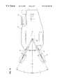
- FIG. 7is a top view showing an alternative embodiment of the apparatus of the present invention showing a vehicle with an offset hitch bracket guiding a string of nested carts into a central cart collection area.
- the present inventionrelates to an apparatus for conveying a plurality of nestable carts.
- the inventionprovides a power operated vehicle capable of being guided by a walking attendant.
- the vehiclehas two rear drive wheels in differential and a front rotatable caster.
- a control handleis offset to the side, and an adjustable hitch is attached to the rear for accepting the lead nestable cart.
- the adjustable hitchpivots at a point proximal to the axle which allows a string of nestable carts to be turned on a sharper radius.
- the inventionallows for increased maneuverability, increased efficiency in the collection and delivery of nestable carts, and improved operational safety.
- the present inventionhas many advantages.
- One advantageis that it allows for greater maneuverability of a string of nested carts.
- the rotatable caster and drive wheel differentialallow a zero turning radius of the vehicle when no carts are attached. With a string of nested carts attached, the hitch pivots through an angle of about 50° to 60°, thereby allowing the vehicle to guide the carts around sharper comers. The turning radius also prevents the carts from turning too quickly which can result in wheel damage.
- the present inventionprovides other advantages as well.
- the control handleallows for a walking attendant to control the vehicle with one hand from a position where obstacles and hazards can be easily seen and avoided.
- Another advantageincludes the increased efficiency in the collection and delivery of the carts to a central collection area.
- a cart conveying vehicleis configured for conveying a plurality of nestable carts.
- the vehicle 100has a main frame 10 which supports a pair of oppositely disposed drive wheels 12 at the rear end of the vehicle and a caster 14 at the forward end of the vehicle.
- the wheels 12are oppositely disposed on an axle 16 and the axle 16 contains a differential 17 .
- the caster 14comprises a tire 14 a , a vertical axle 14 b , and is of construction well known in the art.
- Caster 14is mounted to the main frame 10 .
- the vertical axle 14 ballows the caster 14 to rotate 360°. The full rotation of the caster improves the overall maneuverability of the cart.
- the main frame 10has an outer cover 18 .
- the cover 18shields the inner parts of the vehicle 100 , such as a motor 30 and the axle 16 , from adverse ambient conditions. Ambient conditions such as water and particulate matter can ruin or degrade the inner parts of the vehicle.
- a portion of the cover 18is removable for access to the inner parts of the vehicle.
- the cover 18is attached to the main frame 10 and is constructed of substantially rigid material such as sheet metal.
- the shape of the cover 18is designed to prevent an attendant from riding on the vehicle.
- the cover 18has sloped side walls 18 a that slant towards the front of the vehicle and a sloped front wall 18 b that slant upwardly toward the center of the vehicle. This shape improves the safety of the vehicle in that persons are deterred from standing or sitting on the vehicle.
- a handle 20is adjacent and offset from the front end of the vehicle.
- a bracket 22is disposed vertically and connects the main frame 10 to the handle 20 .
- the handle 20has an accelerator 24 , a brake lever 26 , and a safety switch 61 .
- the accelerator 24 and safety switch 61must be engaged in order for the vehicle to operate.
- the accelerator 24controls the speed of the vehicle.
- the extent of pivotal movement of the accelerator 24determines the amount of current to be supplied to the motor 30 and thus the speed of the vehicle.
- the accelerator 24 and safety switch 61are electrically connected to the motor 30 such that releasing either will cut power to the motor 30 thereby causing the vehicle to decelerate and stop.
- Engaging the brake lever 26stops the vehicle.
- Other conventional braking mechanismscan be incorporated into the vehicle, such as an automatic brake that engages when the accelerator 24 is released.
- the handle 20is offset from center to improve maneuverability and enhance safety.
- the vehicleis designed to be operated with one hand so that the operator can use the other hand for necessary functions such as opening doors and removing obstacles.
- an operatorstands to the front side of the vehicle with one hand grasping the handle 20 to control the operation of the vehicle.
- the safety switch 61is configured such that the palm of the operator's hand engages the switch when grasping the handle 20 , leaving the rest of the hand free to control the accelerator 24 and brake lever 26 .
- the accelerator 24 and brake lever 26are configured such that the operator can conveniently operate both mechanisms with the same hand that engages the safety switch 61 .
- the accelerator 24is conveniently operated with the index finger.
- the location of the handle 20 proximal the rotatable caster 14 and the distribution of the weight of the vehicleenhances vehicle maneuverability.
- the weight of the vehicleis substantially concentrated over the drive axle 16 . This maximizes the traction of the drive wheels 12 and reduces the weight on the caster 14 .
- This combination of weight distribution and locationmakes the vehicle easier to turn.
- the location of the handle 20allows the operator to guide the vehicle from a forward position where the vehicle path and hazards are easily seen. This enhances safety.
- the motor 30is supported by the main frame 10 .
- a sprocket 36is connected to the drive end of the motor 30 .
- a larger sprocket 38is connected to the end of the axle 16 and is proximal to the sprocket 36 .
- a chain 40engages the sprocket 36 and larger sprocket 38 such that there is a speed reduction drive between the motor 30 and the drive wheels 12 thereby providing a large torque output.
- the axle 16includes a conventional differential 17 such that the drive wheels 12 can rotate in opposite directions.
- the motor 30is electrically connected to a battery 32 .
- the battery 32is supported by the main frame 10 .
- the drive wheels 12are oppositely disposed on the axle 16 via bearings 19 .
- Conventional braking mechanismsare used to stop the vehicle.
- the breaking mechanismconsists of a hydraulic brake caliper 62 supported by the main frame 10 , a brake disk 63 rigidly connected to the axle 16 , and a master cylinder 64 located on the handle 20 .
- the master cylinder 64actuates the hydraulic brake caliper 62 which presses against the brake disk 63 thereby slowing down the vehicle.
- a protective bracket(not shown) is mounted to the frame 10 below the axle 16 .
- the bracketprotects the axle 16 , differential 17 , and breaking mechanism from obstacles on the surface such as potholes, curbs, and speed bumps.
- the motor 30 , battery 32 , and other inner parts of the vehicleare located such that the center of gravity of the vehicle is substantially centered over the center of axle 16 . As mentioned, this distribution of weight enhances traction and maneuverability.
- a hitch 44is located at the rear end of the vehicle for attaching the lead nested cart.
- the hitch 44has a spring biased latching means for securing the front bar of the cart.
- FIG. 3shows the top view of the front bar interlocking with the hitch 44 along with a string of carts nested within the front cart.
- the front bar of the lead cartis secured within a retaining slot 46 .
- the front baris guided into the retaining slot 46 by the curved edge 48 as the hitch vertically pivots about a pivot bar 50 .
- the pivot and resulting vertical movement of the hitchallows for a more efficient collection of carts because the hitch 44 can adjust to compensate for differences in the height of the front bar of different carts.
- the hitchswivels about swivel bar 52 . This swivel also increases the collection efficiency of the carts.
- FIG. 4is a top view of the vehicle showing the hitch 44 in two positions.
- the hitch 44is connected to a bracket 54 .
- the bracket 54is pivotably connected to the main frame 10 by a pivot bearing 56 .
- the pivot bearing 56is located near the axle 16 . This distance between the pivot bearing 56 and axle 16 is minimized in order to improve control.
- the force of the attached string of cartsis focused at the pivot bearing 56 , so a shorter distance between the pivot bearing 56 and axle 16 improves stability.
- the location of the pivot bearing below the axlealso has the advantage of preventing the front of the vehicle from lifting off the ground under extreme loads. Such extreme loads occur when the vehicle is starting, traveling up an incline, or accelerating.
- the pivot bearing 56allows the hitch to pivot independently of the direction of the vehicle which improves maneuverability and control.
- the pivot bearing 56is located along the longitudinal axis of the vehicle and below the centerline of the axle 16 .
- the pivot bearing 56is located within 2 cm to 8 cm of the axle 16 , and preferably 5.3 cm behind the axle 16 .
- the pivot bearing 56is located within 5 cm below the axle 16 , and preferably 3 cm below the axle.
- the bracket 54pivots through an angle.
- the pivot angle of bracket 54is limited by stops 59 .
- Stops 59are connected to the main frame 10 at the rear end of the vehicle. Stops 59 are made of sufficiently rigid material as to withstand repeated wear by the bracket 54 .
- the pivot angle of the hitch bracket 54determines the overall turning radius of the string of nested carts.
- FIG. 5shows the vehicle making a sharp turn, resulting in the full pivot of the hitch bracket 54 and corresponding turning of the nested carts.
- the bracket pivot angleis designed to maximize maneuverability and to maintain control over the nested carts.
- the pivoting of the bracket 54reduces the problem commonly known as “jackknifing.” This occurs when the vehicle is attempting to turn too sharply, and the nested carts cannot turn with the vehicle. The force of the nested carts continues to push the vehicle along the path of the nested carts and resists movement along the path of the vehicle.
- the pivoting of the bracket and the short distance between the pivot bearing 56 and axle 16prevent this “jackknifing.”
- the pivot angle of the hitch bracket 54substantially matches the minimum turning radius of the string of carts so that the vehicle cannot be turned sharper that a string of carts. This prevents “jackknifing.”
- the bracket pivot angleis about 50° to 60° and is preferably 54° as is shown in the drawings.
- FIG. 6is an alternative embodiment of the present invention showing an offset hitch bracket 60 .
- the offset hitch bracket 60is offset such that the path of nested carts is offset from the path of the vehicle.
- the offset distanceis set such that the outside wheel of each nested cart travels in a path outside the vehicle path. The outside wheel of each cart is guided into a cart collection area without removing the string of carts from the vehicle.
- the offsetdecreases the amount of time needed to deposit the carts in a collection area.
- the vehiclehas several additional control features.
- a signal light 69is disposed vertically from the approximate center of the vehicle. The signal light 69 is activated when the motor is on and acts to warn pedestrians that the vehicle is approaching.
- the motor 30has a reversing switch (not shown) to move the vehicle in the reverse direction. The reverse switch is designed to activate a warning beeper when the vehicle is operated in reverse.
- a key switch(not shown) activates the vehicle and is provided to prevent unauthorized operation of the vehicle. The internal workings of such control features are well known.
- the drive wheel differential 17 and caster 14allow the vehicle to fully rotate with a turning radius of substantially zero.
- the vehicledoes not require a turning radius to complete a full turn. This is advantages where the vehicle is operated within a small area, as is common in airports and other commercial establishments. This minimal turning radius provides advantages with a string of carts attached. The string of carts is more maneuverable.
- the force that the carts exert on the vehiclehas minimal effect on the overall handling of the vehicle.
- a lead cartis attached to hitch 44 .
- a front bar on the lead cartis secured in the hitch retaining slot 46 by a spring biased latching means.
- multiple cartsare nested within the lead cart.
- the string of cartsis secured to the cart using conventional methods.
- a rope schematically illustrated at 80 in FIG. 1is attached from the vehicle to the rear cart to prevent the carts from breaking away and to ensure a firmly nested string of carts.
- the ropeis wound about a drum 82 and has a fastening hook 83 to attach to the rear cart.
- the drumis attached to the vehicle.
- the nested string of cartsis typically guided to a central collection area.
- the nested string of cartsare released from the vehicle and each cart is returned to the collection area.
- One type of collection areaaccepts the rear wheel of a cart through guided wheel slots.
- FIG. 7shows such a rental and return station.
- a guided wheel slot 70retains the cart for the next customer.
- Such collection areasoften are designed as rental stations.
- the vehicle in FIG. 7has an offset hitch bracket which correspondingly offsets the path of the nested carts from the path of the vehicle.
- the offsetallows the carts to be guided into the wheel guide slot 70 with the use of the vehicle. In such an arrangement, there is no need to release the carts prior to deposit and manually return each cart.
Landscapes
- Engineering & Computer Science (AREA)
- Chemical & Material Sciences (AREA)
- Combustion & Propulsion (AREA)
- Transportation (AREA)
- Mechanical Engineering (AREA)
- Handcart (AREA)
Abstract
Description
Claims (14)
Priority Applications (3)
| Application Number | Priority Date | Filing Date | Title |
|---|---|---|---|
| US08/908,537US6244366B1 (en) | 1997-08-07 | 1997-08-07 | Cart transporter |
| AU45121/97AAU4512197A (en) | 1997-08-07 | 1997-11-11 | Cart transporter |
| DE19752924ADE19752924A1 (en) | 1997-08-07 | 1997-11-28 | Motor-driven vehicle for transporting several nested trolleys |
Applications Claiming Priority (1)
| Application Number | Priority Date | Filing Date | Title |
|---|---|---|---|
| US08/908,537US6244366B1 (en) | 1997-08-07 | 1997-08-07 | Cart transporter |
Publications (1)
| Publication Number | Publication Date |
|---|---|
| US6244366B1true US6244366B1 (en) | 2001-06-12 |
Family
ID=25425947
Family Applications (1)
| Application Number | Title | Priority Date | Filing Date |
|---|---|---|---|
| US08/908,537Expired - Fee RelatedUS6244366B1 (en) | 1997-08-07 | 1997-08-07 | Cart transporter |
Country Status (3)
| Country | Link |
|---|---|
| US (1) | US6244366B1 (en) |
| AU (1) | AU4512197A (en) |
| DE (1) | DE19752924A1 (en) |
Cited By (39)
| Publication number | Priority date | Publication date | Assignee | Title |
|---|---|---|---|---|
| US20030102969A1 (en)* | 2001-12-04 | 2003-06-05 | Parsons Natan E. | Cart fleet management system |
| US20030127813A1 (en)* | 2002-01-07 | 2003-07-10 | Lenkman Thomas E. | Utility transport system |
| US20030231945A1 (en)* | 2002-06-12 | 2003-12-18 | Weatherly Mason C. | Shopping cart mover |
| US20040245030A1 (en)* | 2003-06-09 | 2004-12-09 | Dane Industries, Inc. | Cart pulling vehicle with dual cable drums and dual torsion springs |
| US20040256166A1 (en)* | 2003-05-03 | 2004-12-23 | Holtan Paul D. | Cart mover |
| US20050098364A1 (en)* | 2003-09-23 | 2005-05-12 | Johnson Daniel T. | Power-assisted cart retriever with attenuated power output |
| US20050098362A1 (en)* | 2001-10-26 | 2005-05-12 | Daniel Johnson | Hospital bed power-assist |
| US20050116431A1 (en)* | 2003-10-15 | 2005-06-02 | Holtan Paul D. | Cart coupler assembly for cart collection machines |
| US20050194754A1 (en)* | 2004-03-05 | 2005-09-08 | Honda Motor Co., Ltd. | Cart handle assembly |
| US20050279537A1 (en)* | 2004-06-18 | 2005-12-22 | Ken Nguyen | Motorized vehicle for maneuvering another wheeled apparatus |
| US20060042842A1 (en)* | 2004-08-31 | 2006-03-02 | Berg Jeffrey O | Dual row cart collector and method |
| US20060102392A1 (en)* | 2001-10-26 | 2006-05-18 | Johnson Daniel T | Bed transfer system |
| US20060175100A1 (en)* | 2000-05-11 | 2006-08-10 | Ruschke Jeffrey A | Motorized propulsion system for a bed |
| US20060197295A1 (en)* | 2003-10-15 | 2006-09-07 | Dane Industries, Inc. | Push-pull cart collection device and conversion assembly |
| US20060243500A1 (en)* | 2005-02-25 | 2006-11-02 | Wiff James W | Wheelchair transporter |
| US20060273547A1 (en)* | 2005-06-07 | 2006-12-07 | Holtan Paul D | Hitch Assembly |
| US20070013157A1 (en)* | 2005-07-18 | 2007-01-18 | Wiff James W | Dual hitch assembly |
| US20070018425A1 (en)* | 2005-03-17 | 2007-01-25 | Gilmore Cindy R | Cart restraining system |
| US20070289787A1 (en)* | 2005-02-25 | 2007-12-20 | Dane Industries, Inc. | Wheelchair transporter |
| US20080116651A1 (en)* | 2006-11-16 | 2008-05-22 | Simon Pamela L | Cart |
| US20090008902A1 (en)* | 2007-06-27 | 2009-01-08 | Bart Kylstra | Mounting Assembly for Attaching auxiliary equipment to a wheelchair |
| US20090065272A1 (en)* | 2007-09-06 | 2009-03-12 | Martin James F | Rolltainer transporter |
| US20090178864A1 (en)* | 2008-01-14 | 2009-07-16 | Robinson Kenneth I | Motorized wheelbarrow |
| US20090267322A1 (en)* | 2008-04-11 | 2009-10-29 | Holtan Paul D | Cart transporting apparatus |
| US20100078905A1 (en)* | 2008-09-23 | 2010-04-01 | Paul David Holtan | Cart moving machine |
| US8825263B1 (en)* | 2013-03-12 | 2014-09-02 | Raven Industries, Inc. | Vehicle guidance based on tractor position |
| US9010771B2 (en) | 2009-11-10 | 2015-04-21 | Dane Technologies, Inc. | Utility machine with dual-mode steering |
| DK178498B1 (en)* | 2015-04-13 | 2016-04-18 | Mobile Ind Robots Aps | ROBOT-BASED VEHICLE TO TOUGH A CAR |
| US20160136997A1 (en)* | 2014-11-14 | 2016-05-19 | Alan Polad | Brake Mechanism for Mobile Currency Vaults |
| US9403548B2 (en) | 2014-07-25 | 2016-08-02 | Gatekeeper Systems, Inc. | Monitoring usage or status of cart retrievers |
| EP3138701A1 (en)* | 2005-03-18 | 2017-03-08 | Gatekeeper Systems, Inc. | Two-way communication system for tracking locations and statuses of wheeled vehicles |
| US9669857B1 (en)* | 2015-07-01 | 2017-06-06 | Randall D Rainey | Propulsion device for hand-pushed equipment |
| US9809263B2 (en)* | 2016-01-12 | 2017-11-07 | Bradley T. Mitchell | Articulating cart system |
| CN112339825A (en)* | 2019-08-08 | 2021-02-09 | 株式会社牧田 | Hand-push type carrier |
| US20220080793A1 (en)* | 2020-09-16 | 2022-03-17 | Tata Consultancy Services Limited | Automated carrier tugger mounted on an autonomous mobile robot for tugging a carrier |
| US20230202032A1 (en)* | 2020-06-09 | 2023-06-29 | Mobile Industrial Robots A/S | Gripping system for an autonomous guided vehicle |
| US11891101B1 (en)* | 2022-11-22 | 2024-02-06 | Ryan Dixson | Motorized utility cart assembly |
| US11904920B2 (en) | 2021-11-19 | 2024-02-20 | Raytheon Company | Lift cart with mechanically actuated automatic braking device |
| US20240224848A9 (en)* | 2022-10-25 | 2024-07-11 | Omar Alvarado | Universal remote control conversion kit |
Families Citing this family (1)
| Publication number | Priority date | Publication date | Assignee | Title |
|---|---|---|---|---|
| US12179727B2 (en)* | 2022-10-17 | 2024-12-31 | Ford Global Technologies, Llc | Vehicle brake control |
Citations (11)
| Publication number | Priority date | Publication date | Assignee | Title |
|---|---|---|---|---|
| US2879858A (en) | 1954-09-13 | 1959-03-31 | George W Olson | Battery energized, motor-driven vehicle |
| US3312300A (en) | 1964-11-02 | 1967-04-04 | William D Jones | Power-operated utility cart |
| DE2350308A1 (en) | 1973-10-06 | 1975-04-17 | Wiedemann Fa Konrad | TRANSPORT VEHICLE FOR STACKABLE SHOPPING CART |
| DE2450692A1 (en) | 1974-10-25 | 1976-04-29 | Wilhelm Weller | Re-collection of shopping trolleys - remotely controlled fork stacking truck type vehicle pushes trolleys back to shopping centre |
| US4185711A (en) | 1976-03-09 | 1980-01-29 | Richard Lawrence | Motorized cart |
| WO1990011922A1 (en) | 1989-04-10 | 1990-10-18 | Rosecall Pty. Ltd. | Vehicle for conveying trolleys |
| US5082074A (en) | 1988-07-09 | 1992-01-21 | Lafis Lagertechnik Fischer Gmbh & Co Kg | Transport vehicle |
| US5439069A (en) | 1992-11-27 | 1995-08-08 | Beeler; Jimmy A. | Nested cart pusher |
| US5573078A (en)* | 1994-08-18 | 1996-11-12 | Stringer; Calvin R. | Steerable, self-powered shopping cart towing apparatus and method for making same |
| US5860485A (en)* | 1996-05-28 | 1999-01-19 | Rhino Craft, Inc. | Grocery cart mover |
| US5934694A (en)* | 1996-02-13 | 1999-08-10 | Dane Industries | Cart retriever vehicle |
- 1997
- 1997-08-07USUS08/908,537patent/US6244366B1/ennot_activeExpired - Fee Related
- 1997-11-11AUAU45121/97Apatent/AU4512197A/ennot_activeAbandoned
- 1997-11-28DEDE19752924Apatent/DE19752924A1/ennot_activeWithdrawn
Patent Citations (12)
| Publication number | Priority date | Publication date | Assignee | Title |
|---|---|---|---|---|
| US2879858A (en) | 1954-09-13 | 1959-03-31 | George W Olson | Battery energized, motor-driven vehicle |
| US3312300A (en) | 1964-11-02 | 1967-04-04 | William D Jones | Power-operated utility cart |
| DE2350308A1 (en) | 1973-10-06 | 1975-04-17 | Wiedemann Fa Konrad | TRANSPORT VEHICLE FOR STACKABLE SHOPPING CART |
| DE2450692A1 (en) | 1974-10-25 | 1976-04-29 | Wilhelm Weller | Re-collection of shopping trolleys - remotely controlled fork stacking truck type vehicle pushes trolleys back to shopping centre |
| US4185711A (en) | 1976-03-09 | 1980-01-29 | Richard Lawrence | Motorized cart |
| US5082074A (en) | 1988-07-09 | 1992-01-21 | Lafis Lagertechnik Fischer Gmbh & Co Kg | Transport vehicle |
| WO1990011922A1 (en) | 1989-04-10 | 1990-10-18 | Rosecall Pty. Ltd. | Vehicle for conveying trolleys |
| US5322306A (en)* | 1989-04-10 | 1994-06-21 | Rosecall Pty Ltd. | Vehicle for conveying trolleys |
| US5439069A (en) | 1992-11-27 | 1995-08-08 | Beeler; Jimmy A. | Nested cart pusher |
| US5573078A (en)* | 1994-08-18 | 1996-11-12 | Stringer; Calvin R. | Steerable, self-powered shopping cart towing apparatus and method for making same |
| US5934694A (en)* | 1996-02-13 | 1999-08-10 | Dane Industries | Cart retriever vehicle |
| US5860485A (en)* | 1996-05-28 | 1999-01-19 | Rhino Craft, Inc. | Grocery cart mover |
Cited By (82)
| Publication number | Priority date | Publication date | Assignee | Title |
|---|---|---|---|---|
| US20060175100A1 (en)* | 2000-05-11 | 2006-08-10 | Ruschke Jeffrey A | Motorized propulsion system for a bed |
| US7481286B2 (en)* | 2000-05-11 | 2009-01-27 | Hill-Rom Services, Inc. | Motorized propulsion system for a bed |
| US20050098362A1 (en)* | 2001-10-26 | 2005-05-12 | Daniel Johnson | Hospital bed power-assist |
| US20060102392A1 (en)* | 2001-10-26 | 2006-05-18 | Johnson Daniel T | Bed transfer system |
| US7219754B2 (en) | 2001-10-26 | 2007-05-22 | Dane Industries, Inc. | Hospital bed power-assist |
| US7533742B2 (en) | 2001-10-26 | 2009-05-19 | Dane Industries, Inc. | Bed transfer system |
| US20070145707A1 (en)* | 2001-10-26 | 2007-06-28 | Dane Industries, Inc. | Hospital bed power-assist |
| US7199709B2 (en) | 2001-12-04 | 2007-04-03 | Arichell Technologies, Inc. | Cart fleet management system |
| US20030102969A1 (en)* | 2001-12-04 | 2003-06-05 | Parsons Natan E. | Cart fleet management system |
| US7134515B2 (en)* | 2002-01-07 | 2006-11-14 | Lenkman Thomas E | Utility transport system |
| US20030127813A1 (en)* | 2002-01-07 | 2003-07-10 | Lenkman Thomas E. | Utility transport system |
| US20030231945A1 (en)* | 2002-06-12 | 2003-12-18 | Weatherly Mason C. | Shopping cart mover |
| US20040256166A1 (en)* | 2003-05-03 | 2004-12-23 | Holtan Paul D. | Cart mover |
| US6880652B2 (en)* | 2003-06-09 | 2005-04-19 | Dane Industries, Inc. | Cart pulling vehicle with dual cable drums and dual torsion springs |
| US20040245030A1 (en)* | 2003-06-09 | 2004-12-09 | Dane Industries, Inc. | Cart pulling vehicle with dual cable drums and dual torsion springs |
| US7389836B2 (en) | 2003-09-23 | 2008-06-24 | Dane Industries, Inc. | Power-assisted cart retriever with attenuated power output |
| US7493979B2 (en)* | 2003-09-23 | 2009-02-24 | Dane Industries, Inc. | Power-assisted cart retriever with attenuated power output |
| US20050098364A1 (en)* | 2003-09-23 | 2005-05-12 | Johnson Daniel T. | Power-assisted cart retriever with attenuated power output |
| US20080257618A1 (en)* | 2003-09-23 | 2008-10-23 | Johnson Daniel T | Power-assisted cart retriever with attenuated power output |
| US7549651B2 (en) | 2003-10-15 | 2009-06-23 | Dane Industries, Inc. | Cart coupler assembly for cart collection machines |
| US20050116431A1 (en)* | 2003-10-15 | 2005-06-02 | Holtan Paul D. | Cart coupler assembly for cart collection machines |
| US7571914B2 (en) | 2003-10-15 | 2009-08-11 | Dane Industries, Inc. | Push-pull cart collection device and conversion assembly |
| WO2005037624A3 (en)* | 2003-10-15 | 2006-04-20 | Dane Ind | Cart coupler assembly for cart collection machines |
| US20060197295A1 (en)* | 2003-10-15 | 2006-09-07 | Dane Industries, Inc. | Push-pull cart collection device and conversion assembly |
| US20070181352A1 (en)* | 2003-10-15 | 2007-08-09 | Dane Industries, Inc. | Cart coupler assembly for cart collection machines |
| US7198283B2 (en)* | 2004-03-05 | 2007-04-03 | Honda Motor Co., Ltd. | Cart handle assembly |
| US20050194754A1 (en)* | 2004-03-05 | 2005-09-08 | Honda Motor Co., Ltd. | Cart handle assembly |
| US20050279537A1 (en)* | 2004-06-18 | 2005-12-22 | Ken Nguyen | Motorized vehicle for maneuvering another wheeled apparatus |
| US7395886B2 (en) | 2004-08-31 | 2008-07-08 | Gatekeeper Systems (Hk) Limited | Dual row cart collector and method |
| US20060042842A1 (en)* | 2004-08-31 | 2006-03-02 | Berg Jeffrey O | Dual row cart collector and method |
| US20060243500A1 (en)* | 2005-02-25 | 2006-11-02 | Wiff James W | Wheelchair transporter |
| US20070289787A1 (en)* | 2005-02-25 | 2007-12-20 | Dane Industries, Inc. | Wheelchair transporter |
| US20070018425A1 (en)* | 2005-03-17 | 2007-01-25 | Gilmore Cindy R | Cart restraining system |
| EP3138701A1 (en)* | 2005-03-18 | 2017-03-08 | Gatekeeper Systems, Inc. | Two-way communication system for tracking locations and statuses of wheeled vehicles |
| US11981365B2 (en) | 2005-03-18 | 2024-05-14 | Gatekeeper Systems, Inc. | System for monitoring and controlling shopping cart usage |
| US9914470B2 (en) | 2005-03-18 | 2018-03-13 | Gatekeeper Systems, Inc. | System with wheel assembly that communicates with display unit of human propelled cart |
| US11230313B2 (en) | 2005-03-18 | 2022-01-25 | Gatekeeper Systems, Inc. | System for monitoring and controlling shopping cart usage |
| US10745040B2 (en)* | 2005-03-18 | 2020-08-18 | Gatekeeper Systems, Inc. | Motorized cart retriever for monitoring cart status |
| US9758185B2 (en) | 2005-03-18 | 2017-09-12 | Gatekeeper Systems, Inc. | Wheel assembly and antenna design for cart tracking system |
| US9783218B2 (en) | 2005-03-18 | 2017-10-10 | Gatekeeper Systems, Inc. | Zone-based command transmissions to cart wheel assemblies |
| US9963162B1 (en) | 2005-03-18 | 2018-05-08 | Gatekeeper Systems, Inc. | Cart monitoring system supporting unicast and multicast command transmissions to wheel assemblies |
| US10023216B2 (en) | 2005-03-18 | 2018-07-17 | Gatekeeper Systems, Inc. | Cart monitoring system capable of authorizing cart exit events |
| US11299189B2 (en)* | 2005-03-18 | 2022-04-12 | Gatekeeper Systems, Inc. | Motorized cart retriever for monitoring cart status |
| US10189494B2 (en) | 2005-03-18 | 2019-01-29 | Gatekeeper Systems, Inc. | Cart monitoring system with wheel assembly capable of visually signaling cart status |
| US11358621B2 (en) | 2005-03-18 | 2022-06-14 | Gatekeeper Systems, Inc. | System for monitoring and controlling shopping cart usage |
| US20190118845A1 (en)* | 2005-03-18 | 2019-04-25 | Gatekeeper Systems, Inc. | Motorized cart retriever for monitoring cart status |
| US7857342B2 (en) | 2005-06-07 | 2010-12-28 | Dane Technologies, Inc. | Hitch assembly |
| US20060273547A1 (en)* | 2005-06-07 | 2006-12-07 | Holtan Paul D | Hitch Assembly |
| US20070013157A1 (en)* | 2005-07-18 | 2007-01-18 | Wiff James W | Dual hitch assembly |
| US20080116651A1 (en)* | 2006-11-16 | 2008-05-22 | Simon Pamela L | Cart |
| US8651507B2 (en)* | 2007-06-27 | 2014-02-18 | Daedalus Wings, Inc. | Mounting assembly for attaching auxiliary equipment to a wheelchair |
| US20090008902A1 (en)* | 2007-06-27 | 2009-01-08 | Bart Kylstra | Mounting Assembly for Attaching auxiliary equipment to a wheelchair |
| US7712558B2 (en) | 2007-09-06 | 2010-05-11 | Mh Logistics Corp. | Rolltainer transporter |
| US20090065272A1 (en)* | 2007-09-06 | 2009-03-12 | Martin James F | Rolltainer transporter |
| US8235153B2 (en)* | 2008-01-14 | 2012-08-07 | Robinson Kenneth I | Motorized wheelbarrow |
| US20090178864A1 (en)* | 2008-01-14 | 2009-07-16 | Robinson Kenneth I | Motorized wheelbarrow |
| US20090267322A1 (en)* | 2008-04-11 | 2009-10-29 | Holtan Paul D | Cart transporting apparatus |
| US8360459B2 (en) | 2008-04-11 | 2013-01-29 | Dane Technologies, Inc. | Cart transporting apparatus |
| US8684373B2 (en) | 2008-09-23 | 2014-04-01 | Dane Technologies, Inc. | Cart moving machine |
| US20100078905A1 (en)* | 2008-09-23 | 2010-04-01 | Paul David Holtan | Cart moving machine |
| US9010771B2 (en) | 2009-11-10 | 2015-04-21 | Dane Technologies, Inc. | Utility machine with dual-mode steering |
| US8825263B1 (en)* | 2013-03-12 | 2014-09-02 | Raven Industries, Inc. | Vehicle guidance based on tractor position |
| US9403548B2 (en) | 2014-07-25 | 2016-08-02 | Gatekeeper Systems, Inc. | Monitoring usage or status of cart retrievers |
| US10124821B2 (en) | 2014-07-25 | 2018-11-13 | Gatekeeper Systems, Inc. | Monitoring usage or status of cart retrievers |
| US9962993B2 (en)* | 2014-11-14 | 2018-05-08 | Alan Polad | Brake mechanism for mobile currency vaults |
| US20160136997A1 (en)* | 2014-11-14 | 2016-05-19 | Alan Polad | Brake Mechanism for Mobile Currency Vaults |
| US10668617B2 (en)* | 2015-04-13 | 2020-06-02 | Mobile Industrial Robots A/S | Robotic cart pulling vehicle for automated pulling of carts |
| DK178498B1 (en)* | 2015-04-13 | 2016-04-18 | Mobile Ind Robots Aps | ROBOT-BASED VEHICLE TO TOUGH A CAR |
| US9669857B1 (en)* | 2015-07-01 | 2017-06-06 | Randall D Rainey | Propulsion device for hand-pushed equipment |
| US9809263B2 (en)* | 2016-01-12 | 2017-11-07 | Bradley T. Mitchell | Articulating cart system |
| US10106213B2 (en) | 2016-01-12 | 2018-10-23 | Bradley T. Mitchell | Articulating cart system |
| CN112339825A (en)* | 2019-08-08 | 2021-02-09 | 株式会社牧田 | Hand-push type carrier |
| US20220212705A1 (en)* | 2019-08-08 | 2022-07-07 | Makita Corporation | Handcart |
| US11390310B2 (en)* | 2019-08-08 | 2022-07-19 | Makita Corporation | Handcart |
| US11801882B2 (en)* | 2019-08-08 | 2023-10-31 | Makita Corporation | Handcart |
| US20230202032A1 (en)* | 2020-06-09 | 2023-06-29 | Mobile Industrial Robots A/S | Gripping system for an autonomous guided vehicle |
| US12403591B2 (en)* | 2020-06-09 | 2025-09-02 | Mobile Industrial Robots A/S | Gripping system for an autonomous guided vehicle |
| US11577560B2 (en)* | 2020-09-16 | 2023-02-14 | Tata Consultancy Services Limited | Automated carrier tugger mounted on an autonomous mobile robot for tugging a carrier |
| US20220080793A1 (en)* | 2020-09-16 | 2022-03-17 | Tata Consultancy Services Limited | Automated carrier tugger mounted on an autonomous mobile robot for tugging a carrier |
| US11904920B2 (en) | 2021-11-19 | 2024-02-20 | Raytheon Company | Lift cart with mechanically actuated automatic braking device |
| US20240224848A9 (en)* | 2022-10-25 | 2024-07-11 | Omar Alvarado | Universal remote control conversion kit |
| US11891101B1 (en)* | 2022-11-22 | 2024-02-06 | Ryan Dixson | Motorized utility cart assembly |
Also Published As
| Publication number | Publication date |
|---|---|
| DE19752924A1 (en) | 1999-02-11 |
| AU4512197A (en) | 1999-02-18 |
Similar Documents
| Publication | Publication Date | Title |
|---|---|---|
| US6244366B1 (en) | Cart transporter | |
| US4096920A (en) | Powered shopping cart and trailer | |
| CA2417365C (en) | Omni direction vehicle | |
| CA1325778C (en) | Thrust and traction transport vehicle | |
| US5860485A (en) | Grocery cart mover | |
| US5439069A (en) | Nested cart pusher | |
| US5573078A (en) | Steerable, self-powered shopping cart towing apparatus and method for making same | |
| US6435803B1 (en) | Shopping cart collection vehicle and method | |
| US6168367B1 (en) | Shopping cart collection vehicle and method | |
| EP0972438B1 (en) | Wheel locking mechanism | |
| US6832884B2 (en) | Shopping cart collection vehicle and method | |
| GB2124985A (en) | Steerable drive unit for wheelchair | |
| US20030231945A1 (en) | Shopping cart mover | |
| EP0183774A1 (en) | SAFETY DEVICE FOR CARRIERS. | |
| US20060048534A1 (en) | Self propelled food & beverage receptacle | |
| US7712556B2 (en) | Omni direction vehicle | |
| GB2332405A (en) | Improvements in shopping trolleys | |
| EP0711698B1 (en) | Distribution or transport trolley | |
| WO1995008449A1 (en) | Castors | |
| GB2349126A (en) | A steerable trolley which uses differential braking of the rear castors | |
| EP0442874B1 (en) | A carriage for transferring objects | |
| EP0728076B1 (en) | Trolley having a castor locking device | |
| GB2406315A (en) | Light personal vehicle | |
| EP0681628A1 (en) | Apparatus for laying road cones | |
| EP4212407B1 (en) | Wheeled transport device |
Legal Events
| Date | Code | Title | Description |
|---|---|---|---|
| AS | Assignment | Owner name:SMARTE CARTE, INC., MINNESOTA Free format text:ASSIGNMENT OF ASSIGNORS INTEREST;ASSIGNORS:OTTERSON, DANIEL L.;STEPHAN, PAUL F.;REEL/FRAME:008963/0186;SIGNING DATES FROM 19970918 TO 19970919 | |
| AS | Assignment | Owner name:WELLS FARGO BANK, NATIONAL ASSOCIATION, AS ADMINIS Free format text:SECURITY INTEREST;ASSIGNOR:SMARTE CARTE, INC.;REEL/FRAME:009980/0492 Effective date:19990408 | |
| AS | Assignment | Owner name:WELLS FARGO BANK, NATIONAL ASSOCIATION, AS ADMINIS Free format text:GRANT OF PATENT SECURITY INTEREST;ASSIGNOR:SMARTE CARTE CORPORATION;REEL/FRAME:014119/0641 Effective date:20031029 | |
| AS | Assignment | Owner name:BLACK DIAMOND COMMERCIAL FINANCE, LLC, VIRGIN ISLA Free format text:APPOINTMENT OF SUCCESSOR ADMINISTRATIVE AGENT;ASSIGNOR:WELLS FARGO BANK, NATIONAL ASSOCIATION;REEL/FRAME:015177/0023 Effective date:20040517 Owner name:SMARTE CARTE CORPORATION, MINNESOTA Free format text:APPOINTMENT OF SUCCESSOR ADMINISTRATIVE AGENT;ASSIGNOR:WELLS FARGO BANK, NATIONAL ASSOCIATION;REEL/FRAME:015177/0023 Effective date:20040517 | |
| FPAY | Fee payment | Year of fee payment:4 | |
| AS | Assignment | Owner name:SMARTE CARTE CORPORATION, MINNESOTA Free format text:RELEASE OF LIEN IN PATENTS PURSUANT TO 1996 CREDIT AGREEMENT AND 1999 CREDIT AGREEMENT, AS AMENDED;ASSIGNOR:BLACK DIAMOND COMMERCIAL FINANCE, LLC;REEL/FRAME:016323/0393 Effective date:20050526 Owner name:BLACK DIAMOND COMMERCIAL FINANCE, LLC, VIRGIN ISLA Free format text:SECURITY AGREEMENT;ASSIGNOR:SMARTE CARTE CORPORATION;REEL/FRAME:016323/0299 Effective date:20050526 | |
| AS | Assignment | Owner name:SMARTE CARTE CORPORATION, MINNESOTA Free format text:RELEASE OF SECURITY INTEREST IN PATENTS;ASSIGNOR:BLACK DIAMOND COMMERCIAL FINANCE, LLC;REEL/FRAME:017344/0731 Effective date:20060228 | |
| REMI | Maintenance fee reminder mailed | ||
| LAPS | Lapse for failure to pay maintenance fees | ||
| STCH | Information on status: patent discontinuation | Free format text:PATENT EXPIRED DUE TO NONPAYMENT OF MAINTENANCE FEES UNDER 37 CFR 1.362 | |
| FP | Lapsed due to failure to pay maintenance fee | Effective date:20090612 |