US6243223B1 - Disk drive with servo burst phasing for improved linearity and off-track performance with a wide reading transducer - Google Patents
Disk drive with servo burst phasing for improved linearity and off-track performance with a wide reading transducerDownload PDFInfo
- Publication number
- US6243223B1 US6243223B1US09/007,698US769898AUS6243223B1US 6243223 B1US6243223 B1US 6243223B1US 769898 AUS769898 AUS 769898AUS 6243223 B1US6243223 B1US 6243223B1
- Authority
- US
- United States
- Prior art keywords
- servo
- burst
- servo burst
- transducer
- angularly
- Prior art date
- Legal status (The legal status is an assumption and is not a legal conclusion. Google has not performed a legal analysis and makes no representation as to the accuracy of the status listed.)
- Expired - Lifetime
Links
- 101000606504Drosophila melanogaster Tyrosine-protein kinase-like otkProteins0.000titledescription9
- 230000005381magnetic domainEffects0.000claimsdescription18
- 238000006073displacement reactionMethods0.000claimsdescription11
- 230000007704transitionEffects0.000claimsdescription8
- 230000006872improvementEffects0.000claimsdescription2
- 230000001939inductive effectEffects0.000description13
- 230000035945sensitivityEffects0.000description11
- 238000000034methodMethods0.000description5
- 238000010586diagramMethods0.000description4
- 238000009826distributionMethods0.000description3
- 238000004519manufacturing processMethods0.000description3
- 230000008569processEffects0.000description3
- 238000000926separation methodMethods0.000description3
- 230000000712assemblyEffects0.000description2
- 238000000429assemblyMethods0.000description2
- 230000018199S phaseEffects0.000description1
- 230000008859changeEffects0.000description1
- 230000001627detrimental effectEffects0.000description1
- 230000012447hatchingEffects0.000description1
- 238000012886linear functionMethods0.000description1
- 239000000696magnetic materialSubstances0.000description1
- 238000005259measurementMethods0.000description1
- 238000012856packingMethods0.000description1
- ISEUFVQQFVOBCY-UHFFFAOYSA-NprometonChemical compoundCOC1=NC(NC(C)C)=NC(NC(C)C)=N1ISEUFVQQFVOBCY-UHFFFAOYSA-N0.000description1
- 238000003860storageMethods0.000description1
Images


Classifications
- G—PHYSICS
- G11—INFORMATION STORAGE
- G11B—INFORMATION STORAGE BASED ON RELATIVE MOVEMENT BETWEEN RECORD CARRIER AND TRANSDUCER
- G11B5/00—Recording by magnetisation or demagnetisation of a record carrier; Reproducing by magnetic means; Record carriers therefor
- G11B5/48—Disposition or mounting of heads or head supports relative to record carriers ; arrangements of heads, e.g. for scanning the record carrier to increase the relative speed
- G11B5/58—Disposition or mounting of heads or head supports relative to record carriers ; arrangements of heads, e.g. for scanning the record carrier to increase the relative speed with provision for moving the head for the purpose of maintaining alignment of the head relative to the record carrier during transducing operation, e.g. to compensate for surface irregularities of the latter or for track following
- G11B5/596—Disposition or mounting of heads or head supports relative to record carriers ; arrangements of heads, e.g. for scanning the record carrier to increase the relative speed with provision for moving the head for the purpose of maintaining alignment of the head relative to the record carrier during transducing operation, e.g. to compensate for surface irregularities of the latter or for track following for track following on disks
- G11B5/59688—Servo signal format patterns or signal processing thereof, e.g. dual, tri, quad, burst signal patterns
Definitions
- the present inventionrelates generally to rotating magnetic disk drives and, more particularly, to a disk drive having an improved servo burst pattern that better accommodates a wide reading transducer and a wider range of transducer widths.
- each surface of each diskcontains a plurality of concentric data tracks angularly divided into a plurality of data sectors.
- special servo informationis provided on this disk or another disk to determine the position of the head.
- the most popular form of servois called “embedded servo” wherein the servo information is written on this disk in a plurality of servo sectors that are angularly spaced from one another and interspersed between data sectors around the track.
- Each servo sectorgenerally comprises a track identification (ID) field and a group of servo bursts which the servo control system samples to align the transducer head with or relative to a particular data track.
- Each servo burstis conventionally formed from a series of magnetic transitions defined by an alternating pattern of magnetic domains.
- the servo control systemmoves the transducer toward a desired track during a coarse “seek” mode using the track ID field as a control input. Once the transducer head is generally over the desired track, the servo control system uses the servo bursts to keep the transducer head over that track in a fine “track follow” mode.
- the transducergenerally reads the servo bursts to produce a position error signal (PES) that is 0 when the transducer is at a particular radial position.
- PESposition error signal
- the write transducer's widthdefines the very minimum data track pitch.
- the servo informationtherefore, must define a data track pitch that is slightly wider than the write transducer.
- the data track pitchis typically defined to be about 125% wider than the nominal width of the write transducer and conversely, therefore, the write transducer is about 80% of the track pitch. The exact percentage will vary somewhat from 80%, from drive to drive, since the width of the write transducer will vary from nominal due to normal manufacturing distributions.
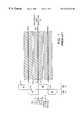
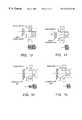
- FIG. 1schematically represents an older drive having only two angularly successive servo burst regions 250 , 350 per servo sector, only two servo burst pairs (e.g. 212 , 312 ) per data track (e.g. 412 ), and an inductive head in which the same transducer 200 (inductive gap) both reads and writes data.
- the R/W transducer 200records “100%” servo bursts 212 , 312 that stretch from data track center to data track center. Each burst, therefore, is 100% as wide as the data track pitch.
- the servo bursts associated with each data trackare typically designated as an A burst and a B burst with reference to their corresponding angular servo burst region 250 , 350 .
- the A and B bursts 212 , 312define a burst pair centerline 412 that coincides with the data track centerline (not separately numbered).
- the servo pattern of FIG. 1is subject to nonlinear regions because the R/W transducer “sees” too little. With only two bursts and one burst pair centerline per data track, the R/W transducer may be completely over one of the bursts and no longer pass over any part of the other burst if the transducer is displaced too far from the burst pair centerline.
- the 80% R/W head 200 of FIG. 1, for example,can only be displaced by a maximum of 40% of a data track pitch from the burst pair centerline 412 and still pass over at least a portion of both bursts 212 , 312 . This results in “blind spots” or “gaps” where the head position is ambiguous.
- the industrysubsequently added more 100% C and D bursts in order to fill the gaps between the A and B bursts.
- the C and D burstsare placed in “quadrature” with the A and B bursts in that the edges of the C and D bursts are aligned with the centers of the A and B bursts.
- there are two burst pair centerlines per data track pitchi.e. one burst pair centerline every 50% of a data track pitch.
- the 80% R/W transducer 200therefore, will always pass over an A/B pair or a C/D pair because it is always within 25% of a data track pitch from an A/B or C/D burst pair centerline.
- FIG. 2is a schematic plan view of a typical MR head 120 having an inductive write transducer 90 and a separate, magnetoresitive read transducer 100 .
- An MR head 120can advantageously recover data in disk drives of higher areal density than is possible with an inductive head.
- an MR headalso presents a number of disadvantages.
- the separate read and write transducers 90 , 100are necessarily spaced apart from one another along the length of the supporting structure known as a “slider.” As a result, their radial separation varies from ID to OD as the MR head 120 is moved in an arc by a swing-type actuator.
- the drive industrypresently compensates for the variable radial separation between the transducers 90 , 100 by “microjogging” the read head 100 relative to a given burst pair centerline by an amount corresponding to the radial displacement at that cylinder.
- This jogging solutiongenerally requires separate and distinct track following procedures for reading and writing.
- the drivecan microjog when writing data or when reading data, but it is preferable to track follow on the burst pair centerline while writing and only jog when reading so that the data is consistently written to the same location.
- the read transducer 100is “micro-jogged” away from the null position of the burst pair centerline where the PES ⁇ 0, in order to align the read transducer 100 with the recorded data.
- An MR headis sometimes called a “Write Wide/Read Narrow” head because the inductive write transducer 90 is usually wider than the magnetoresistive read transducer 100 , as shown in FIG. 2 .
- the read transducer 90is only about 66% of a data track pitch.
- the relatively narrow read transducer 100physically limits the microjogging operation to one half of the read transducer's width, i.e. to about ⁇ 30%. As described in more detail below, however, the actual linear microjogging maximum is even less than 30%, because the magnetoresistive read transducer 100 has an uneven “microtrack profile” (i.e.
- the typical 66% magnetoresistive read transducer 100can only be microjogged by about ⁇ 20% of a data track pitch and still provide a servo signal that varies in adequate linear proportion to displacement from a burst pair centerline.
- the drive industryincreased the number of burst pair centerlines per data track pitch in order to reduce the linearity problem caused by the narrow linear width of the magnetoresistive read transducer 100 .
- the additional burst pair centerlinesare added by packing more servo bursts into the circumferential or radial dimensions of the disk. Adding more servo bursts in the radial dimension is generally preferred because it does not increase the angular width of the servo wedges and thereby reduce the area available for storing data. Adding more servo bursts in the radial dimension does, however, require bursts that are narrower than 100% of a data track pitch.
- the narrow bursts and additional burst pair centerlinesreduces one linearity problem, but creates a new linearity problem by reducing the width of the servo bursts relative to the width of the read transducer while putting neighboring, radially adjacent servo bursts closer together.
- a neighboring servo burstmay undesirably affect the signal amplitude detected by the read transducer 100 in a given angular servo burst region. This is particularly true as the read transducer 100 is microjogged away from a burst pair centerline and moved closer to the neighboring, radially adjacent servo burst.
- the read headmay begin to “see” the radially adjacent B burst.
- the read headmay be microjogged 15% of a data track pitch from the A/B burst pair centerline, involving a first B burst, and begin to see more and more of a second, radially adjacent B burst, thereby distorting the B portion amplitude signal used to provide the PES that is typically defined as (A ⁇ B)/(A+B).
- the present inventionis applicable to a read transducer of any type, but is especially helpful in the context of MR heads which are necessarily jogged during operation, are often manufactured and used in a wide range of physical width distributions to keep costs down, are subject to increased side reading due to shielding, and are more likely to be used with narrow servo bursts needed to define additional burst pair centerlines.
- the inventionmay be regarded as a disk drive having a sampled servo system controller and a disk wherein the disk has a plurality of angularly spaced servo wedges, each servo wedge having a plurality of angularly aligned servo burst fields that are radially adjacent to one another, each servo wedge further comprising a radially adjacent pair of the angularly aligned servo burst fields that are spaced apart by an erase area and wherein the radially adjacent pair of angularly aligned servo burst fields are recorded in opposing phase.
- the inventionmay also be regarded as an improved magnetic disk drive having (1) a magnetic disk with first and second angularly successive servo burst regions that each contain a plurality of radially spaced servo bursts formed from a plurality of alternating magnetic domains which define a plurality of magnetic transitions; (2) a plurality of burst pair centerlines defined by a plurality of servo burst pairs where each servo burst pair comprises a first servo burst from the first servo burst region and a second servo burst from the second servo burst region; and (3) a read transducer which detects the magnetic transitions while passing over the first and second angularly successive servo burst regions and develops first and second signal amplitudes representative of a radial displacement between the read transducer and a burst pair centerline, the improvement comprising a 180 degree phase relationship between the alternating magnetic domains of each radially spaced servo burst in
- FIG. 1schematically represents a prior art drive that uses only two circumferentially successive A and B bursts 212 , 312 per data track 412 and an inductive head in which the same transducer 200 both reads and writes data;
- FIG. 2is a conceptual plan view of an MR head 120 which comprises separate transducers, an inductive write transducer 90 that is typically about p80% of a track pitch and a magnetoresistive read transducer 100 having a physical width W P that is typically about 66% of a track pitch;
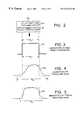
- FIG. 3is a “microtrack profile” or sensitivity plot 101 for an ideal read transducer wherein the transducer is uniformly sensitive across its width and is not subject to side reading such that its electrical width W E equals its physical width W P ;
- FIG. 4is a microtrack profile 102 for a typical magnetoresistive read transducer 100 that is asymmetrical and subject to side reading such that its electrical width W E is significantly wider than its physical width W P ;
- FIG. 5is a microtrack profile 103 for a typical inductive read transducer 200 that is relatively symmetrical, but is still subject to side reading such that its electrical width W E is wider than its physical width W P ;
- FIG. 6shows a wide read transducer 100 in several positions relative to a conventional servo pattern wherein radially adjacent bursts (e.g. 311 and 312 ) have magnetic domains # 1 , # 2 , # 3 , # 4 that were recorded in phase with one another such that when the read transducer 100 ′ passes over both bursts 311 , 312 in some offtrack positions (e.g. positions ⁇ 3 and ⁇ 4 ), the PES becomes nonlinear and no longer changes;
- radially adjacent burstse.g. 311 and 312
- FIG. 6shows a wide read transducer 100 in several positions relative to a conventional servo pattern wherein radially adjacent bursts (e.g. 311 and 312 ) have magnetic domains # 1 , # 2 , # 3 , # 4 that were recorded in phase with one another such that when the read transducer 100 ′ passes over both bursts 311 , 312 in some offtrack positions (e.
- FIG. 6Ais a plot of PES versus mechanical position for the conventional servo pattern of FIG. 6 with data points corresponding to the exemplary head positions and resulting PES values of FIG. 6 emphasized for clarity;
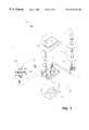
- FIG. 7is an exploded perspective view of a magnetic disk drive 10 having a head disk assembly 11 (HDA) including a head stack assembly 20 (HSA) which carries a magnetoresistive head 120 (MR head) over concentric data tracks, servo tracks, and associated servo bursts on the surface of a disk 12 ;
- HDAhead disk assembly 11
- HSAhead stack assembly 20
- MR headmagnetoresistive head 120
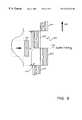
- FIG. 8is a schematic, block diagram of a servo control loop 18 used to position a head 120 over a surface of a disk 12 in the disk drive 10 of FIG. 7;
- FIG. 9shows a magnetoresistive read transducer 100 and the corresponding microtrack sensitivity profile of FIG. 4 traveling on a burst pair centerline 712 defined by an A burst 512 and a B burst 612 having radially adjacent bursts 611 , 513 that were recorded in accordance with the present invention
- FIG. 10is similar to FIG. 9 except that the read transducer 100 has been jogged away from the burst pair centerline 712 , toward the OD in this case, such that it begins to “see” a radially adjacent B burst 611 in addition to the B burst 612 which defines the burst pair centerline 712 ;
- FIG. 11shows a wide read transducer 100 ′ in several positions relative to a servo pattern according to the present invention wherein radially adjacent bursts (e.g. 611 , 612 ) have magnetic domains # 1 , # 2 , # 3 , # 4 which were recorded 180 degrees out of phase with one another such that the PES continues to change in linear proportion to displacement even when the read transducer 100 ′ passes over both bursts 611 , 612 in an offtrack position (e.g. positions ⁇ 3 and ⁇ 4 );
- radially adjacent burstse.g. 611 , 612
- FIG. 11shows a wide read transducer 100 ′ in several positions relative to a servo pattern according to the present invention wherein radially adjacent bursts (e.g. 611 , 612 ) have magnetic domains # 1 , # 2 , # 3 , # 4 which were recorded 180 degrees out of phase with one another such that the PES continues to change in linear proportion
- FIG. 11Ais a plot of PES versus mechanical position for the innovative servo pattern of FIG. 11 with data points corresponding to the exemplary head positions and resulting PES values of FIG. 11 emphasized for clarity;
- FIGS. 12-13are schematic diagrams showing the burst amplitude signals developed by an ideal transducer in an ontrack and 50% offtrack position.
- FIGS. 14-15are schematic diagrams showing the burst amplitude signals that are incorrectly developed by a wide transducer given normal burst phasing and that are correctly developed given burst phasing according to the present invention.
- the present inventionmakes innovative use of a servo track writer (STW), a manufacturing fixture used to write servo information on the disks of an HDA.
- STWservo track writer
- the STWmechanically moves the HDA's actuator to a given reference position precisely measured by a laser interferometer or other precision measurement device.
- the HDAis then driven to write the servo track information for that position.
- the servo track writing process of precisely measured displacement and servo track writingis repeated to write all required servo tracks across the disk.
- the STWaccurately controls phase alignment in order to maintain phase coherence between radially adjacent track ID fields.
- This phase alignmentin combination with a gray coding arrangement, permits the head to straddle two or more servo tracks while seeking or settling and still obtain reasonably valid track ID information.
- the present inventionuses the STW's phase alignment capability in the unique context of radially adjacent servo bursts that are separated by an erase field, recording each such servo burst 180 degrees out of phase with each radially adjacent servo burst.
- FIGS. 3, 4 , and 5respectively, illustrate the microtrack sensitivity profiles (also called crosstrack profiles) 101 , 102 , 103 for an ideal read transducer, for a typical magnetoresistive read transducer 100 , and for a typical inductive R/W transducer 200 .
- a microtrack profileis developed by measuring the signal amplitude while repeatedly passing the transducer 100 , 200 over a narrow burst pattern of about 10-15% of a data track pitch and indexing the transducer 100 , 200 in the radial direction in small “microtrack” portions.
- FIG. 3shows the “perfect” sensitivity profile 100 of an ideal transducer. Its sensitivity is uniform across the physical width W P of the transducer and drops abruptly to zero at either end such that the transducer's electrical width W E equals its physical width W P .
- the typical magnetoresistive read transducer 100has a “microtrack” sensitivity profile 102 that is asymmetrical.
- FIGS. 4 and 5also show that both magnetoresistive and inductive read transducers 100 , 200 have an electrical width WE that exceeds the their physical width W P because both are sensitive to magnetic energy that lies to either side. Consequently, under certain conditions, both types of read transducers may be improperly influenced by a neighboring, radially adjacent servo burst that would ordinarily not be “seen” by an ideal read transducer.
- the electrical width WE of a read transducerdepends on the transducer's physical width W P and its “side reading” sensitivity.
- the physical width W Pvaries given typical manufacturing tolerances.
- the width distribution for a batch of read transducers of 66% nominal widthmay vary from 60% to 75%, or more, depending on the manufacturer's controls.
- the electrical width W Ewill always exceed the physical width W P .
- FIG. 7shows the principal components of a disk drive 10 in which a burst phasing technique according to the present invention may be implemented.
- the disk drive 10having integrated drive electronics, comprises a head disk assembly (HDA) 11 and a controller circuit board 14 .
- HDAhead disk assembly
- the HDA 11 of FIG. 7comprises a magnetic disk 12 ( 2 shown), a spindle motor 13 for rapidly rotating the disk 12 , and a head stack assembly 20 located next to the disk 12 .
- the head stack assembly 20comprises a swing-type actuator assembly 30 having a voice coil 50 , an actuator body 40 , and an actuator arm 60 .
- At least one head gimbal assembly 100extends from each actuator arm 60 and carries a head such as a magnetoresistive head (MR head) 120 (see FIG. 2) over the disk 12 .
- MR headmagnetoresistive head
- the head stack assembly 20is located so that the head 120 of the head gimbal assembly 100 is biased towards and moveable over the disk 12 .
- the HDA's storage capacitymay be increased, as shown in FIG. 1, by including several disks 12 and a head stack assembly 20 having a vertical “stack” of head gimbal assemblies 100 and associated heads 140 for each surface of each disk 12 , the head gimbal assemblies 100 supported by multiple actuator arm 60 .
- FIG. 8is a schematic, block diagram of a servo control loop 18 used to position a transducer head 120 over a surface of a disk 12 in the disk drive 10 of FIG. 8 .
- servo electronics within the controller circuit board 14control the actuator 20 based on servo signals fed back from the transducer head 120 .
- a detailed description of the servo control loopis unnecessary because its general operation is well known in the industry.
- burstsgroups or “bursts” of magnetic transitions are recorded in a radially displaced fashion within angularly successive servo burst regions 250 , 350 making up a servo sector. Where only two bursts are used per data track, such bursts are usually designated as the “A” burst and the “B” burst. The radial displacement in such case places the A burst to one side of the burst pair centerline and the B burst to the other side.
- the A and B burstsare circumferentially displaced from one another since they are contained in the angularly successive servo burst regions 250 , 350 . Accordingly, the head passes over the A burst and then over the B burst. If the head is aligned with the burst pair centerline, then the head will pass over equal amounts of the A and B bursts and the servo electronics will develop a Position Error Signal (PES) equal to zero. If the head is displaced from the centerline, then the head will pass over more of the A burst or over more of the B burst so that the PES will be nonzero, the sign of the PES indicating the direction of displacement. The PES is used by the servo electronics to attain and then maintain a desired position.
- PESPosition Error Signal
- FIG. 2schematically shows a typical MR head 120 wherein the read and write transducers are separate and are typically of different widths.
- the inductive write transducer 90is typically about 80% of a track pitch and the magnetoresistive read transducer 100 has a physical width W P that is typically about 66% of a track pitch.
- W Pthe physical width
- the microtrack profile of the typical MR head 120is asymmetric and extends to either side of the read transducer 100 .
- FIGS. 9 and 10show a read transducer 100 traveling along relative to a burst pair centerline 712 defined by an A burst 512 and a B burst 612 .
- Radially adjacent bursts 513 and 611are spaced apart from A burst 512 and B burst 612 respectively by erase areas 515 and 615 , created during the process of servowriting the disk.
- the read transducer 100is shown adjacent to and in alignment with its corresponding microtrack profile of FIG. 4 in order to emphasize that its electrical width W E may span radially adjacent servo bursts 611 or 613 in addition to the two servo bursts 512 , 612 which define the current burst pair centerline 712 .
- the read transducer 100is traveling right on the burst pair centerline 712 and its electrical width WE is passing only over the defining bursts 512 , 612 .
- the read transducer 100has been jogged toward the OD such that the transducer 100 will electrically, although not physically, pass over a portion 611 ′ of a radially adjacent B burst 611 in addition passing over all of the defining bursts 512 , and a portion 612 ′ of defining burst 612 .
- the signal amplitude from the electrically passed over portion 611 ′ of the radially adjacent B burst 611would simply be added to the signal amplitude from the physically and electrically passed over portion 612 ′ of the B burst 612 .
- the servo burstswere recorded in accordance with the present invention, as shown in FIGS. 9, 10 and 11 , then the portion 611 ′ is beneficially out of phase with the portion 612 ′. As a result, the contribution from the electrically passed over portion 611 ′ is not erroneously added to the PES, but rather is subtracted therefrom.
- FIG. 6shows a hypothetical head 100 ′ passing over two radially adjacent A bursts 212 , 213 , and two radially adjacent B bursts 311 , 312 that were recorded in the conventional manner with the magnetic domains of each radially adjacent burst in phase with all other radially adjacent bursts.
- Typical servo burstscontain about eleven magnetic domains and ten transitions.
- the servo bursts of FIG. 6are shown with only four magnetic domains # 1 , # 2 , # 3 , # 4 .
- the magnetic domains # 1 , # 2 , # 3 , # 4are electrically in phase with one another in that the # 1 domains were both recorded with the write current flowing in a first direction, the # 2 domains were both recorded with the write current flowing in a second opposite direction, the # 3 were both recorded with the write current again flowing in the first direction, and the # 4 domains were both recorded with the write current again flowing in the second direction.
- FIG. 6specifically shows the burst amplitude signals developed by the transducer head 100 when it passes over the servo bursts in five different positions 0 , ⁇ 1 , ⁇ 2 , ⁇ 3 and ⁇ 4 .
- the transducer 100 ′In positions 0 , ⁇ 1 , and ⁇ 2 the transducer 100 ′ passes over a portion of the A burst 212 and a portion of the B burst 312 in proportionally varying amounts which result in linear PES (A ⁇ B) values of 0, 2 and 4 PES units. If the transducer 100 ′ is positioned farther, however, such as at positions ⁇ 3 and ⁇ 4 , then it begins to read the radially adjacent B burst 311 and the PES no longer changes, as shown in FIG. 6 and corresponding FIG. 6 A. As the transducer 100 ′ moves over the radially adjacent B burst 311 , it moves away from the original B burst 312 .
- FIG. 6Ashows the PES values and transducer displacement as a percentage of the servo track pitch for the servo pattern of FIG. 6 . As shown, there is a limited amount of offtrack movement before the read transducer 100 ′ no longer develops a PES signal that is proportional to displacement. The five data points corresponding to the five head positions of FIG. 6 are emphasized for clarity.
- FIG. 11in contrast with FIG. 6, shows two radially adjacent A bursts 512 , 513 , and two radially adjacent B bursts 611 , 612 and erase areas 515 , 615 that were recorded in accordance with the present invention.
- the burstswere uniquely recorded with “burst phasing” by alternating the write current for the component domains # 1 , # 2 , # 3 , # 4 of each radially adjacent servo burst.
- the # 1 domains of the B bursts 611 , 612are 180 degrees electrically out of phase with one another, as are the # 2 , # 3 , and # 4 domains.
- FIG. 11Ais a graph of the PES developed as a function of mechanical offtrack position of the read transducer 100 ′ given the innovative servo burst pattern of FIG. 11 .
- the burst phasing aspect of the present inventionpermits the system to develop a PES that varies ideally as a linear function of mechanical position from ⁇ 50% to +50% of a servo track pitch.
- an ideal transducerthat has no side sensitivity and is precisely the same width as the servo bursts A 1 and B 1 is traveling along the burst pair centerline. As shown in FIG. 12, when the ideal transducer passes over the servo burst A 1 , B 1 the transducer detects corresponding burst signals of equal amplitude as shown directly below the bursts.
- the ideal transducer 100 ′has been moved offtrack by 50% of a servo track pitch such that the ideal transducer is passing completely over burst B 1 and not at all over burst A 1 or radially adjacent burst A 2 .
- the ideal transducerdevelops the amplitude signals shown below the bursts the first of which is correctly flat.
- a real wide-reading transducer 100 ′is traveling over conventional servo bursts and is positioned at the same 50% offtrack amount as shown in FIG. 13 .
- the transducer 100 ′because of the side sensitivity of the transducer 100 ′, it detects portions of radially adjacent bursts A 1 and A 2 . Accordingly, the transducer 100 ′ will develop the amplitude signals shown below the conventional servo bursts.
- the servo control systemwould incorrectly determine the transducer's position if it relied on the signals developed by the wide-reading transducer 100 given normal burst phasing.
- servo bursts with burst phasingin accordance with the present invention are used.
- the portion of the amplitude signal developed by burst A 1is completely canceled by the portion of the amplitude signal developed by burst A 2 .
- the burst amplitude signalsappear as they should.
- the present inventionuniquely develops the two amplitude signals that are used in the standard position error formula (A ⁇ B) in a conventional fashion from two bursts (e.g. A n , B n ) and in an innovative fashion from more than two servo bursts (e.g. B n ⁇ 1 , A n , B n or A n , B n , A n+1 ).
- a ⁇ Bstandard position error formula
Landscapes
- Engineering & Computer Science (AREA)
- Signal Processing (AREA)
- Moving Of The Head To Find And Align With The Track (AREA)
Abstract
Description
Claims (7)
Priority Applications (1)
| Application Number | Priority Date | Filing Date | Title |
|---|---|---|---|
| US09/007,698US6243223B1 (en) | 1998-01-15 | 1998-01-15 | Disk drive with servo burst phasing for improved linearity and off-track performance with a wide reading transducer |
Applications Claiming Priority (1)
| Application Number | Priority Date | Filing Date | Title |
|---|---|---|---|
| US09/007,698US6243223B1 (en) | 1998-01-15 | 1998-01-15 | Disk drive with servo burst phasing for improved linearity and off-track performance with a wide reading transducer |
Publications (1)
| Publication Number | Publication Date |
|---|---|
| US6243223B1true US6243223B1 (en) | 2001-06-05 |
Family
ID=21727666
Family Applications (1)
| Application Number | Title | Priority Date | Filing Date |
|---|---|---|---|
| US09/007,698Expired - LifetimeUS6243223B1 (en) | 1998-01-15 | 1998-01-15 | Disk drive with servo burst phasing for improved linearity and off-track performance with a wide reading transducer |
Country Status (1)
| Country | Link |
|---|---|
| US (1) | US6243223B1 (en) |
Cited By (112)
| Publication number | Priority date | Publication date | Assignee | Title |
|---|---|---|---|---|
| US20020097518A1 (en)* | 2000-12-12 | 2002-07-25 | Storage Technology Corporation | Track position error determination |
| US6671790B2 (en) | 2001-06-04 | 2003-12-30 | Seagate Technology Llc | Optimizing reader to writer offset compensation for a disc drive |
| US20050013043A1 (en)* | 2003-07-14 | 2005-01-20 | Jun Ashiwa | Reference magnetic signal recording device and method of manufacturing the same |
| US6980389B1 (en) | 2004-02-27 | 2005-12-27 | Western Digital Technologies, Inc. | Disk drive having a disk including a servo burst pattern having a normal servo burst field and a quadrature servo burst field |
| US20060007569A1 (en)* | 2004-07-21 | 2006-01-12 | Fuji Photo Film Co., Ltd. | Amplitude servo pattern, magnetic recording medium and the manufacturing method, patterned magnetic transfer master substrate used in the manufacturing method, and magnetic recording/reproducing apparatus |
| US7023637B1 (en) | 2004-06-01 | 2006-04-04 | Western Digital Technologies, Inc. | Disk drive having a disk including a servo burst pattern that improves the signal to noise ratio during track following for writing |
| US7027257B1 (en) | 2004-04-01 | 2006-04-11 | Western Digital Technologies, Inc. | Disk drive having a disk including a servo burst pattern in which a phase difference between radially adjacent servo bursts is less than 180 degrees |
| US7710676B1 (en) | 2008-03-27 | 2010-05-04 | Western Digital Technologies, Inc. | Disk drive comprising gray code implemented with servo bursts |
| US7916415B1 (en) | 2008-03-27 | 2011-03-29 | Western Digital Technologies, Inc. | Disk drive decoding binary sequence from phases of servo bursts |
| US8824081B1 (en) | 2012-03-13 | 2014-09-02 | Western Digital Technologies, Inc. | Disk drive employing radially coherent reference pattern for servo burst demodulation and fly height measurement |
| US8830617B1 (en) | 2013-05-30 | 2014-09-09 | Western Digital Technologies, Inc. | Disk drive adjusting state estimator to compensate for unreliable servo data |
| US8879191B1 (en) | 2012-11-14 | 2014-11-04 | Western Digital Technologies, Inc. | Disk drive modifying rotational position optimization algorithm to achieve target performance for limited stroke |
| US8891191B1 (en) | 2014-05-06 | 2014-11-18 | Western Digital Technologies, Inc. | Data storage device initializing read signal gain to detect servo seed pattern |
| US8891194B1 (en) | 2013-05-14 | 2014-11-18 | Western Digital Technologies, Inc. | Disk drive iteratively adapting correction value that compensates for non-linearity of head |
| US8896957B1 (en) | 2013-05-10 | 2014-11-25 | Western Digital Technologies, Inc. | Disk drive performing spiral scan of disk surface to detect residual data |
| US8902539B1 (en) | 2014-05-13 | 2014-12-02 | Western Digital Technologies, Inc. | Data storage device reducing seek power consumption |
| US8902538B1 (en) | 2013-03-29 | 2014-12-02 | Western Digital Technologies, Inc. | Disk drive detecting crack in microactuator |
| US8913342B1 (en) | 2014-03-21 | 2014-12-16 | Western Digital Technologies, Inc. | Data storage device adjusting range of microactuator digital-to-analog converter based on operating temperature |
| US8917474B1 (en) | 2011-08-08 | 2014-12-23 | Western Digital Technologies, Inc. | Disk drive calibrating a velocity profile prior to writing a spiral track |
| US8917475B1 (en) | 2013-12-20 | 2014-12-23 | Western Digital Technologies, Inc. | Disk drive generating a disk locked clock using radial dependent timing feed-forward compensation |
| US8922940B1 (en) | 2014-05-27 | 2014-12-30 | Western Digital Technologies, Inc. | Data storage device reducing spindle motor voltage boost during power failure |
| US8922931B1 (en) | 2013-05-13 | 2014-12-30 | Western Digital Technologies, Inc. | Disk drive releasing variable amount of buffered write data based on sliding window of predicted servo quality |
| US8922938B1 (en) | 2012-11-02 | 2014-12-30 | Western Digital Technologies, Inc. | Disk drive filtering disturbance signal and error signal for adaptive feed-forward compensation |
| US8922937B1 (en) | 2012-04-19 | 2014-12-30 | Western Digital Technologies, Inc. | Disk drive evaluating multiple vibration sensor outputs to enable write-protection |
| US8929021B1 (en) | 2012-03-27 | 2015-01-06 | Western Digital Technologies, Inc. | Disk drive servo writing from spiral tracks using radial dependent timing feed-forward compensation |
| US8929022B1 (en) | 2012-12-19 | 2015-01-06 | Western Digital Technologies, Inc. | Disk drive detecting microactuator degradation by evaluating frequency component of servo signal |
| US8934186B1 (en) | 2014-03-26 | 2015-01-13 | Western Digital Technologies, Inc. | Data storage device estimating servo zone to reduce size of track address |
| US8937784B1 (en) | 2012-08-01 | 2015-01-20 | Western Digital Technologies, Inc. | Disk drive employing feed-forward compensation and phase shift compensation during seek settling |
| US8941939B1 (en) | 2013-10-24 | 2015-01-27 | Western Digital Technologies, Inc. | Disk drive using VCM BEMF feed-forward compensation to write servo data to a disk |
| US8941945B1 (en) | 2014-06-06 | 2015-01-27 | Western Digital Technologies, Inc. | Data storage device servoing heads based on virtual servo tracks |
| US8947819B1 (en) | 2012-08-28 | 2015-02-03 | Western Digital Technologies, Inc. | Disk drive implementing hysteresis for primary shock detector based on a more sensitive secondary shock detector |
| US8953278B1 (en) | 2011-11-16 | 2015-02-10 | Western Digital Technologies, Inc. | Disk drive selecting disturbance signal for feed-forward compensation |
| US8953271B1 (en) | 2013-05-13 | 2015-02-10 | Western Digital Technologies, Inc. | Disk drive compensating for repeatable run out selectively per zone |
| US8958169B1 (en) | 2014-06-11 | 2015-02-17 | Western Digital Technologies, Inc. | Data storage device re-qualifying state estimator while decelerating head |
| US8970979B1 (en) | 2013-12-18 | 2015-03-03 | Western Digital Technologies, Inc. | Disk drive determining frequency response of actuator near servo sample frequency |
| US8982501B1 (en) | 2014-09-22 | 2015-03-17 | Western Digital Technologies, Inc. | Data storage device compensating for repeatable disturbance when commutating a spindle motor |
| US8982490B1 (en) | 2014-04-24 | 2015-03-17 | Western Digital Technologies, Inc. | Data storage device reading first spiral track while simultaneously writing second spiral track |
| US8995082B1 (en) | 2011-06-03 | 2015-03-31 | Western Digital Technologies, Inc. | Reducing acoustic noise in a disk drive when exiting idle mode |
| US8995075B1 (en) | 2012-06-21 | 2015-03-31 | Western Digital Technologies, Inc. | Disk drive adjusting estimated servo state to compensate for transient when crossing a servo zone boundary |
| US9001454B1 (en) | 2013-04-12 | 2015-04-07 | Western Digital Technologies, Inc. | Disk drive adjusting phase of adaptive feed-forward controller when reconfiguring servo loop |
| US9007714B1 (en) | 2014-07-18 | 2015-04-14 | Western Digital Technologies Inc. | Data storage device comprising slew rate anti-windup compensation for microactuator |
| US9013825B1 (en) | 2014-03-24 | 2015-04-21 | Western Digital Technologies, Inc. | Electronic system with vibration management mechanism and method of operation thereof |
| US9013824B1 (en) | 2014-06-04 | 2015-04-21 | Western Digital Technologies, Inc. | Data storage device comprising dual read sensors and dual servo channels to improve servo demodulation |
| US9025269B1 (en) | 2014-01-02 | 2015-05-05 | Western Digital Technologies, Inc. | Disk drive compensating for cycle slip of disk locked clock when reading mini-wedge |
| US9026728B1 (en) | 2013-06-06 | 2015-05-05 | Western Digital Technologies, Inc. | Disk drive applying feed-forward compensation when writing consecutive data tracks |
| US9047901B1 (en) | 2013-05-28 | 2015-06-02 | Western Digital Technologies, Inc. | Disk drive measuring spiral track error by measuring a slope of a spiral track across a disk radius |
| US9047932B1 (en) | 2014-03-21 | 2015-06-02 | Western Digital Technologies, Inc. | Data storage device adjusting a power loss threshold based on samples of supply voltage |
| US9047919B1 (en) | 2013-03-12 | 2015-06-02 | Western Digitial Technologies, Inc. | Disk drive initializing servo read channel by reading data preceding servo preamble during access operation |
| US9053726B1 (en) | 2014-01-29 | 2015-06-09 | Western Digital Technologies, Inc. | Data storage device on-line adapting disturbance observer filter |
| US9053727B1 (en) | 2014-06-02 | 2015-06-09 | Western Digital Technologies, Inc. | Disk drive opening spiral crossing window based on DC and AC spiral track error |
| US9053712B1 (en) | 2014-05-07 | 2015-06-09 | Western Digital Technologies, Inc. | Data storage device reading servo sector while writing data sector |
| US9058826B1 (en) | 2014-02-13 | 2015-06-16 | Western Digital Technologies, Inc. | Data storage device detecting free fall condition from disk speed variations |
| US9058827B1 (en) | 2013-06-25 | 2015-06-16 | Western Digitial Technologies, Inc. | Disk drive optimizing filters based on sensor signal and disturbance signal for adaptive feed-forward compensation |
| US9058834B1 (en) | 2013-11-08 | 2015-06-16 | Western Digital Technologies, Inc. | Power architecture for low power modes in storage devices |
| US9064537B1 (en) | 2013-09-13 | 2015-06-23 | Western Digital Technologies, Inc. | Disk drive measuring radial offset between heads by detecting a difference between ramp contact |
| US9076471B1 (en) | 2013-07-31 | 2015-07-07 | Western Digital Technologies, Inc. | Fall detection scheme using FFS |
| US9076473B1 (en) | 2014-08-12 | 2015-07-07 | Western Digital Technologies, Inc. | Data storage device detecting fly height instability of head during load operation based on microactuator response |
| US9076490B1 (en) | 2012-12-12 | 2015-07-07 | Western Digital Technologies, Inc. | Disk drive writing radial offset spiral servo tracks by reading spiral seed tracks |
| US9076472B1 (en) | 2014-08-21 | 2015-07-07 | Western Digital (Fremont), Llc | Apparatus enabling writing servo data when disk reaches target rotation speed |
| US9093105B2 (en) | 2011-12-09 | 2015-07-28 | Western Digital Technologies, Inc. | Disk drive charging capacitor using motor supply voltage during power failure |
| US9099147B1 (en) | 2014-09-22 | 2015-08-04 | Western Digital Technologies, Inc. | Data storage device commutating a spindle motor using closed-loop rotation phase alignment |
| US9111575B1 (en) | 2014-10-23 | 2015-08-18 | Western Digital Technologies, Inc. | Data storage device employing adaptive feed-forward control in timing loop to compensate for vibration |
| US9111562B2 (en) | 2012-02-17 | 2015-08-18 | Marvell International Ltd. | Recording medium and a method of writing servo information on the same |
| US9129630B1 (en) | 2014-12-16 | 2015-09-08 | Western Digital Technologies, Inc. | Data storage device employing full servo sectors on first disk surface and mini servo sectors on second disk surface |
| US9142235B1 (en) | 2009-10-27 | 2015-09-22 | Western Digital Technologies, Inc. | Disk drive characterizing microactuator by injecting sinusoidal disturbance and evaluating feed-forward compensation values |
| US9142249B1 (en) | 2013-12-06 | 2015-09-22 | Western Digital Technologies, Inc. | Disk drive using timing loop control signal for vibration compensation in servo loop |
| US9142225B1 (en) | 2014-03-21 | 2015-09-22 | Western Digital Technologies, Inc. | Electronic system with actuator control mechanism and method of operation thereof |
| US9141177B1 (en) | 2014-03-21 | 2015-09-22 | Western Digital Technologies, Inc. | Data storage device employing glitch compensation for power loss detection |
| US9147428B1 (en) | 2013-04-24 | 2015-09-29 | Western Digital Technologies, Inc. | Disk drive with improved spin-up control |
| US9147418B1 (en) | 2013-06-20 | 2015-09-29 | Western Digital Technologies, Inc. | Disk drive compensating for microactuator gain variations |
| US9153283B1 (en) | 2014-09-30 | 2015-10-06 | Western Digital Technologies, Inc. | Data storage device compensating for hysteretic response of microactuator |
| US9165583B1 (en) | 2014-10-29 | 2015-10-20 | Western Digital Technologies, Inc. | Data storage device adjusting seek profile based on seek length when ending track is near ramp |
| US9171567B1 (en) | 2014-05-27 | 2015-10-27 | Western Digital Technologies, Inc. | Data storage device employing sliding mode control of spindle motor |
| US9171568B1 (en) | 2014-06-25 | 2015-10-27 | Western Digital Technologies, Inc. | Data storage device periodically re-initializing spindle motor commutation sequence based on timing data |
| US9208808B1 (en) | 2014-04-22 | 2015-12-08 | Western Digital Technologies, Inc. | Electronic system with unload management mechanism and method of operation thereof |
| US9208810B1 (en) | 2014-04-24 | 2015-12-08 | Western Digital Technologies, Inc. | Data storage device attenuating interference from first spiral track when reading second spiral track |
| US9208815B1 (en) | 2014-10-09 | 2015-12-08 | Western Digital Technologies, Inc. | Data storage device dynamically reducing coast velocity during seek to reduce power consumption |
| US9214175B1 (en) | 2015-03-16 | 2015-12-15 | Western Digital Technologies, Inc. | Data storage device configuring a gain of a servo control system for actuating a head over a disk |
| US9230592B1 (en) | 2014-12-23 | 2016-01-05 | Western Digital Technologies, Inc. | Electronic system with a method of motor spindle bandwidth estimation and calibration thereof |
| US9230593B1 (en) | 2014-12-23 | 2016-01-05 | Western Digital Technologies, Inc. | Data storage device optimizing spindle motor power when transitioning into a power failure mode |
| US9245577B1 (en) | 2015-03-26 | 2016-01-26 | Western Digital Technologies, Inc. | Data storage device comprising spindle motor current sensing with supply voltage noise attenuation |
| US9245560B1 (en) | 2015-03-09 | 2016-01-26 | Western Digital Technologies, Inc. | Data storage device measuring reader/writer offset by reading spiral track and concentric servo sectors |
| US9245540B1 (en) | 2014-10-29 | 2016-01-26 | Western Digital Technologies, Inc. | Voice coil motor temperature sensing circuit to reduce catastrophic failure due to voice coil motor coil shorting to ground |
| US9251823B1 (en) | 2014-12-10 | 2016-02-02 | Western Digital Technologies, Inc. | Data storage device delaying seek operation to avoid thermal asperities |
| US9269386B1 (en) | 2014-01-29 | 2016-02-23 | Western Digital Technologies, Inc. | Data storage device on-line adapting disturbance observer filter |
| US9286925B1 (en) | 2015-03-26 | 2016-03-15 | Western Digital Technologies, Inc. | Data storage device writing multiple burst correction values at the same radial location |
| US9286927B1 (en) | 2014-12-16 | 2016-03-15 | Western Digital Technologies, Inc. | Data storage device demodulating servo burst by computing slope of intermediate integration points |
| US9343094B1 (en) | 2015-03-26 | 2016-05-17 | Western Digital Technologies, Inc. | Data storage device filtering burst correction values before downsampling the burst correction values |
| US9343102B1 (en) | 2015-03-25 | 2016-05-17 | Western Digital Technologies, Inc. | Data storage device employing a phase offset to generate power from a spindle motor during a power failure |
| US9349401B1 (en) | 2014-07-24 | 2016-05-24 | Western Digital Technologies, Inc. | Electronic system with media scan mechanism and method of operation thereof |
| US9350278B1 (en) | 2014-06-13 | 2016-05-24 | Western Digital Technologies, Inc. | Circuit technique to integrate voice coil motor support elements |
| US9355667B1 (en) | 2014-11-11 | 2016-05-31 | Western Digital Technologies, Inc. | Data storage device saving absolute position at each servo wedge for previous write operations |
| US9355676B1 (en) | 2015-03-25 | 2016-05-31 | Western Digital Technologies, Inc. | Data storage device controlling amplitude and phase of driving voltage to generate power from a spindle motor |
| US9361939B1 (en) | 2014-03-10 | 2016-06-07 | Western Digital Technologies, Inc. | Data storage device characterizing geometry of magnetic transitions |
| US9396751B1 (en) | 2015-06-26 | 2016-07-19 | Western Digital Technologies, Inc. | Data storage device compensating for fabrication tolerances when measuring spindle motor current |
| US9407015B1 (en) | 2014-12-29 | 2016-08-02 | Western Digital Technologies, Inc. | Automatic power disconnect device |
| US9418689B2 (en) | 2014-10-09 | 2016-08-16 | Western Digital Technologies, Inc. | Data storage device generating an operating seek time profile as a function of a base seek time profile |
| US9424871B1 (en) | 2012-09-13 | 2016-08-23 | Western Digital Technologies, Inc. | Disk drive correcting an error in a detected gray code |
| US9424868B1 (en) | 2015-05-12 | 2016-08-23 | Western Digital Technologies, Inc. | Data storage device employing spindle motor driving profile during seek to improve power performance |
| US9437231B1 (en) | 2015-09-25 | 2016-09-06 | Western Digital Technologies, Inc. | Data storage device concurrently controlling and sensing a secondary actuator for actuating a head over a disk |
| US9437237B1 (en) | 2015-02-20 | 2016-09-06 | Western Digital Technologies, Inc. | Method to detect power loss through data storage device spindle speed |
| US9454212B1 (en) | 2014-12-08 | 2016-09-27 | Western Digital Technologies, Inc. | Wakeup detector |
| US9471072B1 (en) | 2013-11-14 | 2016-10-18 | Western Digital Technologies, Inc | Self-adaptive voltage scaling |
| US9484733B1 (en) | 2013-09-11 | 2016-11-01 | Western Digital Technologies, Inc. | Power control module for data storage device |
| US9542966B1 (en) | 2015-07-09 | 2017-01-10 | Western Digital Technologies, Inc. | Data storage devices and methods with frequency-shaped sliding mode control |
| US9564162B1 (en) | 2015-12-28 | 2017-02-07 | Western Digital Technologies, Inc. | Data storage device measuring resonant frequency of a shock sensor by applying differential excitation and measuring oscillation |
| US9581978B1 (en) | 2014-12-17 | 2017-02-28 | Western Digital Technologies, Inc. | Electronic system with servo management mechanism and method of operation thereof |
| US9620160B1 (en) | 2015-12-28 | 2017-04-11 | Western Digital Technologies, Inc. | Data storage device measuring resonant frequency of a shock sensor by inserting the shock sensor into an oscillator circuit |
| US9823294B1 (en) | 2013-10-29 | 2017-11-21 | Western Digital Technologies, Inc. | Negative voltage testing methodology and tester |
| US9886285B2 (en) | 2015-03-31 | 2018-02-06 | Western Digital Technologies, Inc. | Communication interface initialization |
| US9899834B1 (en) | 2015-11-18 | 2018-02-20 | Western Digital Technologies, Inc. | Power control module using protection circuit for regulating backup voltage to power load during power fault |
| US9959204B1 (en) | 2015-03-09 | 2018-05-01 | Western Digital Technologies, Inc. | Tracking sequential ranges of non-ordered data |
Citations (4)
| Publication number | Priority date | Publication date | Assignee | Title |
|---|---|---|---|---|
| US4890172A (en) | 1988-09-27 | 1989-12-26 | Digital Equipment Corporation | Automatic servo gain calibration system for a disk drive |
| US5182682A (en)* | 1989-09-29 | 1993-01-26 | Seagate Technology, Inc. | Sectored servo disk formatting |
| US5341255A (en) | 1990-10-17 | 1994-08-23 | Seagate Technology, Inc. | Disc drive head positioning servo system with coherent adjacent track magnetic patterns |
| US5923492A (en)* | 1997-09-30 | 1999-07-13 | Maxtor Corporation | Variable-phase servo burst pattern used to minimize shield-related side readings |
- 1998
- 1998-01-15USUS09/007,698patent/US6243223B1/ennot_activeExpired - Lifetime
Patent Citations (4)
| Publication number | Priority date | Publication date | Assignee | Title |
|---|---|---|---|---|
| US4890172A (en) | 1988-09-27 | 1989-12-26 | Digital Equipment Corporation | Automatic servo gain calibration system for a disk drive |
| US5182682A (en)* | 1989-09-29 | 1993-01-26 | Seagate Technology, Inc. | Sectored servo disk formatting |
| US5341255A (en) | 1990-10-17 | 1994-08-23 | Seagate Technology, Inc. | Disc drive head positioning servo system with coherent adjacent track magnetic patterns |
| US5923492A (en)* | 1997-09-30 | 1999-07-13 | Maxtor Corporation | Variable-phase servo burst pattern used to minimize shield-related side readings |
Cited By (121)
| Publication number | Priority date | Publication date | Assignee | Title |
|---|---|---|---|---|
| US6768606B2 (en)* | 2000-12-12 | 2004-07-27 | Storage Technology Corporation | Track position error determination |
| US20020097518A1 (en)* | 2000-12-12 | 2002-07-25 | Storage Technology Corporation | Track position error determination |
| US6671790B2 (en) | 2001-06-04 | 2003-12-30 | Seagate Technology Llc | Optimizing reader to writer offset compensation for a disc drive |
| US7330321B2 (en)* | 2003-07-14 | 2008-02-12 | Canon Kabushiki Kaisha | Reference magnetic signal recording device and method of manufacturing the same |
| US20050013043A1 (en)* | 2003-07-14 | 2005-01-20 | Jun Ashiwa | Reference magnetic signal recording device and method of manufacturing the same |
| US6980389B1 (en) | 2004-02-27 | 2005-12-27 | Western Digital Technologies, Inc. | Disk drive having a disk including a servo burst pattern having a normal servo burst field and a quadrature servo burst field |
| US7027257B1 (en) | 2004-04-01 | 2006-04-11 | Western Digital Technologies, Inc. | Disk drive having a disk including a servo burst pattern in which a phase difference between radially adjacent servo bursts is less than 180 degrees |
| US7023637B1 (en) | 2004-06-01 | 2006-04-04 | Western Digital Technologies, Inc. | Disk drive having a disk including a servo burst pattern that improves the signal to noise ratio during track following for writing |
| US20060007569A1 (en)* | 2004-07-21 | 2006-01-12 | Fuji Photo Film Co., Ltd. | Amplitude servo pattern, magnetic recording medium and the manufacturing method, patterned magnetic transfer master substrate used in the manufacturing method, and magnetic recording/reproducing apparatus |
| US7522362B2 (en) | 2004-07-21 | 2009-04-21 | Fujifilm Corporation | Amplitude servo pattern, magnetic recording medium and the manufacturing method, patterned magnetic transfer master substrate used in the manufacturing method, and magnetic recording/reproducing apparatus |
| US7710676B1 (en) | 2008-03-27 | 2010-05-04 | Western Digital Technologies, Inc. | Disk drive comprising gray code implemented with servo bursts |
| US7916415B1 (en) | 2008-03-27 | 2011-03-29 | Western Digital Technologies, Inc. | Disk drive decoding binary sequence from phases of servo bursts |
| US9142235B1 (en) | 2009-10-27 | 2015-09-22 | Western Digital Technologies, Inc. | Disk drive characterizing microactuator by injecting sinusoidal disturbance and evaluating feed-forward compensation values |
| US8995082B1 (en) | 2011-06-03 | 2015-03-31 | Western Digital Technologies, Inc. | Reducing acoustic noise in a disk drive when exiting idle mode |
| US8917474B1 (en) | 2011-08-08 | 2014-12-23 | Western Digital Technologies, Inc. | Disk drive calibrating a velocity profile prior to writing a spiral track |
| US8953278B1 (en) | 2011-11-16 | 2015-02-10 | Western Digital Technologies, Inc. | Disk drive selecting disturbance signal for feed-forward compensation |
| US9390749B2 (en) | 2011-12-09 | 2016-07-12 | Western Digital Technologies, Inc. | Power failure management in disk drives |
| US9093105B2 (en) | 2011-12-09 | 2015-07-28 | Western Digital Technologies, Inc. | Disk drive charging capacitor using motor supply voltage during power failure |
| US9275654B2 (en) | 2012-02-17 | 2016-03-01 | Marvell International Ltd. | Method and apparatus for writing servo information on a recording medium |
| US9111562B2 (en) | 2012-02-17 | 2015-08-18 | Marvell International Ltd. | Recording medium and a method of writing servo information on the same |
| US8824081B1 (en) | 2012-03-13 | 2014-09-02 | Western Digital Technologies, Inc. | Disk drive employing radially coherent reference pattern for servo burst demodulation and fly height measurement |
| US8934191B1 (en) | 2012-03-27 | 2015-01-13 | Western Digital Technologies, Inc. | Disk drive generating a disk locked clock using radial dependent timing feed-forward compensation |
| US8929021B1 (en) | 2012-03-27 | 2015-01-06 | Western Digital Technologies, Inc. | Disk drive servo writing from spiral tracks using radial dependent timing feed-forward compensation |
| US8922937B1 (en) | 2012-04-19 | 2014-12-30 | Western Digital Technologies, Inc. | Disk drive evaluating multiple vibration sensor outputs to enable write-protection |
| US8995075B1 (en) | 2012-06-21 | 2015-03-31 | Western Digital Technologies, Inc. | Disk drive adjusting estimated servo state to compensate for transient when crossing a servo zone boundary |
| US9454989B1 (en) | 2012-06-21 | 2016-09-27 | Western Digital Technologies, Inc. | Disk drive adjusting estimated servo state to compensate for transient when crossing a servo zone boundary |
| US8937784B1 (en) | 2012-08-01 | 2015-01-20 | Western Digital Technologies, Inc. | Disk drive employing feed-forward compensation and phase shift compensation during seek settling |
| US8947819B1 (en) | 2012-08-28 | 2015-02-03 | Western Digital Technologies, Inc. | Disk drive implementing hysteresis for primary shock detector based on a more sensitive secondary shock detector |
| US9424871B1 (en) | 2012-09-13 | 2016-08-23 | Western Digital Technologies, Inc. | Disk drive correcting an error in a detected gray code |
| US8922938B1 (en) | 2012-11-02 | 2014-12-30 | Western Digital Technologies, Inc. | Disk drive filtering disturbance signal and error signal for adaptive feed-forward compensation |
| US8879191B1 (en) | 2012-11-14 | 2014-11-04 | Western Digital Technologies, Inc. | Disk drive modifying rotational position optimization algorithm to achieve target performance for limited stroke |
| US9076490B1 (en) | 2012-12-12 | 2015-07-07 | Western Digital Technologies, Inc. | Disk drive writing radial offset spiral servo tracks by reading spiral seed tracks |
| US8929022B1 (en) | 2012-12-19 | 2015-01-06 | Western Digital Technologies, Inc. | Disk drive detecting microactuator degradation by evaluating frequency component of servo signal |
| US9047919B1 (en) | 2013-03-12 | 2015-06-02 | Western Digitial Technologies, Inc. | Disk drive initializing servo read channel by reading data preceding servo preamble during access operation |
| US8902538B1 (en) | 2013-03-29 | 2014-12-02 | Western Digital Technologies, Inc. | Disk drive detecting crack in microactuator |
| US9001454B1 (en) | 2013-04-12 | 2015-04-07 | Western Digital Technologies, Inc. | Disk drive adjusting phase of adaptive feed-forward controller when reconfiguring servo loop |
| US9147428B1 (en) | 2013-04-24 | 2015-09-29 | Western Digital Technologies, Inc. | Disk drive with improved spin-up control |
| US8896957B1 (en) | 2013-05-10 | 2014-11-25 | Western Digital Technologies, Inc. | Disk drive performing spiral scan of disk surface to detect residual data |
| US8953271B1 (en) | 2013-05-13 | 2015-02-10 | Western Digital Technologies, Inc. | Disk drive compensating for repeatable run out selectively per zone |
| US8922931B1 (en) | 2013-05-13 | 2014-12-30 | Western Digital Technologies, Inc. | Disk drive releasing variable amount of buffered write data based on sliding window of predicted servo quality |
| US8891194B1 (en) | 2013-05-14 | 2014-11-18 | Western Digital Technologies, Inc. | Disk drive iteratively adapting correction value that compensates for non-linearity of head |
| US9047901B1 (en) | 2013-05-28 | 2015-06-02 | Western Digital Technologies, Inc. | Disk drive measuring spiral track error by measuring a slope of a spiral track across a disk radius |
| US8830617B1 (en) | 2013-05-30 | 2014-09-09 | Western Digital Technologies, Inc. | Disk drive adjusting state estimator to compensate for unreliable servo data |
| US9026728B1 (en) | 2013-06-06 | 2015-05-05 | Western Digital Technologies, Inc. | Disk drive applying feed-forward compensation when writing consecutive data tracks |
| US9147418B1 (en) | 2013-06-20 | 2015-09-29 | Western Digital Technologies, Inc. | Disk drive compensating for microactuator gain variations |
| US9058827B1 (en) | 2013-06-25 | 2015-06-16 | Western Digitial Technologies, Inc. | Disk drive optimizing filters based on sensor signal and disturbance signal for adaptive feed-forward compensation |
| US9076471B1 (en) | 2013-07-31 | 2015-07-07 | Western Digital Technologies, Inc. | Fall detection scheme using FFS |
| US9484733B1 (en) | 2013-09-11 | 2016-11-01 | Western Digital Technologies, Inc. | Power control module for data storage device |
| US9064537B1 (en) | 2013-09-13 | 2015-06-23 | Western Digital Technologies, Inc. | Disk drive measuring radial offset between heads by detecting a difference between ramp contact |
| US8941939B1 (en) | 2013-10-24 | 2015-01-27 | Western Digital Technologies, Inc. | Disk drive using VCM BEMF feed-forward compensation to write servo data to a disk |
| US9823294B1 (en) | 2013-10-29 | 2017-11-21 | Western Digital Technologies, Inc. | Negative voltage testing methodology and tester |
| US9058834B1 (en) | 2013-11-08 | 2015-06-16 | Western Digital Technologies, Inc. | Power architecture for low power modes in storage devices |
| US9471072B1 (en) | 2013-11-14 | 2016-10-18 | Western Digital Technologies, Inc | Self-adaptive voltage scaling |
| US9142249B1 (en) | 2013-12-06 | 2015-09-22 | Western Digital Technologies, Inc. | Disk drive using timing loop control signal for vibration compensation in servo loop |
| US8970979B1 (en) | 2013-12-18 | 2015-03-03 | Western Digital Technologies, Inc. | Disk drive determining frequency response of actuator near servo sample frequency |
| US8917475B1 (en) | 2013-12-20 | 2014-12-23 | Western Digital Technologies, Inc. | Disk drive generating a disk locked clock using radial dependent timing feed-forward compensation |
| US9025269B1 (en) | 2014-01-02 | 2015-05-05 | Western Digital Technologies, Inc. | Disk drive compensating for cycle slip of disk locked clock when reading mini-wedge |
| US9053726B1 (en) | 2014-01-29 | 2015-06-09 | Western Digital Technologies, Inc. | Data storage device on-line adapting disturbance observer filter |
| US9269386B1 (en) | 2014-01-29 | 2016-02-23 | Western Digital Technologies, Inc. | Data storage device on-line adapting disturbance observer filter |
| US9058826B1 (en) | 2014-02-13 | 2015-06-16 | Western Digital Technologies, Inc. | Data storage device detecting free fall condition from disk speed variations |
| US9361939B1 (en) | 2014-03-10 | 2016-06-07 | Western Digital Technologies, Inc. | Data storage device characterizing geometry of magnetic transitions |
| US8913342B1 (en) | 2014-03-21 | 2014-12-16 | Western Digital Technologies, Inc. | Data storage device adjusting range of microactuator digital-to-analog converter based on operating temperature |
| US9047932B1 (en) | 2014-03-21 | 2015-06-02 | Western Digital Technologies, Inc. | Data storage device adjusting a power loss threshold based on samples of supply voltage |
| US9141177B1 (en) | 2014-03-21 | 2015-09-22 | Western Digital Technologies, Inc. | Data storage device employing glitch compensation for power loss detection |
| US9142225B1 (en) | 2014-03-21 | 2015-09-22 | Western Digital Technologies, Inc. | Electronic system with actuator control mechanism and method of operation thereof |
| US9013825B1 (en) | 2014-03-24 | 2015-04-21 | Western Digital Technologies, Inc. | Electronic system with vibration management mechanism and method of operation thereof |
| US8934186B1 (en) | 2014-03-26 | 2015-01-13 | Western Digital Technologies, Inc. | Data storage device estimating servo zone to reduce size of track address |
| US9208808B1 (en) | 2014-04-22 | 2015-12-08 | Western Digital Technologies, Inc. | Electronic system with unload management mechanism and method of operation thereof |
| US8982490B1 (en) | 2014-04-24 | 2015-03-17 | Western Digital Technologies, Inc. | Data storage device reading first spiral track while simultaneously writing second spiral track |
| US9208810B1 (en) | 2014-04-24 | 2015-12-08 | Western Digital Technologies, Inc. | Data storage device attenuating interference from first spiral track when reading second spiral track |
| US8891191B1 (en) | 2014-05-06 | 2014-11-18 | Western Digital Technologies, Inc. | Data storage device initializing read signal gain to detect servo seed pattern |
| US9053712B1 (en) | 2014-05-07 | 2015-06-09 | Western Digital Technologies, Inc. | Data storage device reading servo sector while writing data sector |
| US8902539B1 (en) | 2014-05-13 | 2014-12-02 | Western Digital Technologies, Inc. | Data storage device reducing seek power consumption |
| US8922940B1 (en) | 2014-05-27 | 2014-12-30 | Western Digital Technologies, Inc. | Data storage device reducing spindle motor voltage boost during power failure |
| US9171567B1 (en) | 2014-05-27 | 2015-10-27 | Western Digital Technologies, Inc. | Data storage device employing sliding mode control of spindle motor |
| US9053727B1 (en) | 2014-06-02 | 2015-06-09 | Western Digital Technologies, Inc. | Disk drive opening spiral crossing window based on DC and AC spiral track error |
| US9013824B1 (en) | 2014-06-04 | 2015-04-21 | Western Digital Technologies, Inc. | Data storage device comprising dual read sensors and dual servo channels to improve servo demodulation |
| US8941945B1 (en) | 2014-06-06 | 2015-01-27 | Western Digital Technologies, Inc. | Data storage device servoing heads based on virtual servo tracks |
| US8958169B1 (en) | 2014-06-11 | 2015-02-17 | Western Digital Technologies, Inc. | Data storage device re-qualifying state estimator while decelerating head |
| US9350278B1 (en) | 2014-06-13 | 2016-05-24 | Western Digital Technologies, Inc. | Circuit technique to integrate voice coil motor support elements |
| US9171568B1 (en) | 2014-06-25 | 2015-10-27 | Western Digital Technologies, Inc. | Data storage device periodically re-initializing spindle motor commutation sequence based on timing data |
| US9007714B1 (en) | 2014-07-18 | 2015-04-14 | Western Digital Technologies Inc. | Data storage device comprising slew rate anti-windup compensation for microactuator |
| US9349401B1 (en) | 2014-07-24 | 2016-05-24 | Western Digital Technologies, Inc. | Electronic system with media scan mechanism and method of operation thereof |
| US9076473B1 (en) | 2014-08-12 | 2015-07-07 | Western Digital Technologies, Inc. | Data storage device detecting fly height instability of head during load operation based on microactuator response |
| US9076472B1 (en) | 2014-08-21 | 2015-07-07 | Western Digital (Fremont), Llc | Apparatus enabling writing servo data when disk reaches target rotation speed |
| US8982501B1 (en) | 2014-09-22 | 2015-03-17 | Western Digital Technologies, Inc. | Data storage device compensating for repeatable disturbance when commutating a spindle motor |
| US9099147B1 (en) | 2014-09-22 | 2015-08-04 | Western Digital Technologies, Inc. | Data storage device commutating a spindle motor using closed-loop rotation phase alignment |
| US9153283B1 (en) | 2014-09-30 | 2015-10-06 | Western Digital Technologies, Inc. | Data storage device compensating for hysteretic response of microactuator |
| US9208815B1 (en) | 2014-10-09 | 2015-12-08 | Western Digital Technologies, Inc. | Data storage device dynamically reducing coast velocity during seek to reduce power consumption |
| US9418689B2 (en) | 2014-10-09 | 2016-08-16 | Western Digital Technologies, Inc. | Data storage device generating an operating seek time profile as a function of a base seek time profile |
| US9111575B1 (en) | 2014-10-23 | 2015-08-18 | Western Digital Technologies, Inc. | Data storage device employing adaptive feed-forward control in timing loop to compensate for vibration |
| US9245540B1 (en) | 2014-10-29 | 2016-01-26 | Western Digital Technologies, Inc. | Voice coil motor temperature sensing circuit to reduce catastrophic failure due to voice coil motor coil shorting to ground |
| US9165583B1 (en) | 2014-10-29 | 2015-10-20 | Western Digital Technologies, Inc. | Data storage device adjusting seek profile based on seek length when ending track is near ramp |
| US9355667B1 (en) | 2014-11-11 | 2016-05-31 | Western Digital Technologies, Inc. | Data storage device saving absolute position at each servo wedge for previous write operations |
| US9454212B1 (en) | 2014-12-08 | 2016-09-27 | Western Digital Technologies, Inc. | Wakeup detector |
| US9251823B1 (en) | 2014-12-10 | 2016-02-02 | Western Digital Technologies, Inc. | Data storage device delaying seek operation to avoid thermal asperities |
| US9286927B1 (en) | 2014-12-16 | 2016-03-15 | Western Digital Technologies, Inc. | Data storage device demodulating servo burst by computing slope of intermediate integration points |
| US9129630B1 (en) | 2014-12-16 | 2015-09-08 | Western Digital Technologies, Inc. | Data storage device employing full servo sectors on first disk surface and mini servo sectors on second disk surface |
| US9581978B1 (en) | 2014-12-17 | 2017-02-28 | Western Digital Technologies, Inc. | Electronic system with servo management mechanism and method of operation thereof |
| US9230593B1 (en) | 2014-12-23 | 2016-01-05 | Western Digital Technologies, Inc. | Data storage device optimizing spindle motor power when transitioning into a power failure mode |
| US9761266B2 (en) | 2014-12-23 | 2017-09-12 | Western Digital Technologies, Inc. | Data storage device optimizing spindle motor power when transitioning into a power failure mode |
| US9230592B1 (en) | 2014-12-23 | 2016-01-05 | Western Digital Technologies, Inc. | Electronic system with a method of motor spindle bandwidth estimation and calibration thereof |
| US9407015B1 (en) | 2014-12-29 | 2016-08-02 | Western Digital Technologies, Inc. | Automatic power disconnect device |
| US9437237B1 (en) | 2015-02-20 | 2016-09-06 | Western Digital Technologies, Inc. | Method to detect power loss through data storage device spindle speed |
| US9245560B1 (en) | 2015-03-09 | 2016-01-26 | Western Digital Technologies, Inc. | Data storage device measuring reader/writer offset by reading spiral track and concentric servo sectors |
| US9959204B1 (en) | 2015-03-09 | 2018-05-01 | Western Digital Technologies, Inc. | Tracking sequential ranges of non-ordered data |
| US9214175B1 (en) | 2015-03-16 | 2015-12-15 | Western Digital Technologies, Inc. | Data storage device configuring a gain of a servo control system for actuating a head over a disk |
| US9355676B1 (en) | 2015-03-25 | 2016-05-31 | Western Digital Technologies, Inc. | Data storage device controlling amplitude and phase of driving voltage to generate power from a spindle motor |
| US9343102B1 (en) | 2015-03-25 | 2016-05-17 | Western Digital Technologies, Inc. | Data storage device employing a phase offset to generate power from a spindle motor during a power failure |
| US9245577B1 (en) | 2015-03-26 | 2016-01-26 | Western Digital Technologies, Inc. | Data storage device comprising spindle motor current sensing with supply voltage noise attenuation |
| US9286925B1 (en) | 2015-03-26 | 2016-03-15 | Western Digital Technologies, Inc. | Data storage device writing multiple burst correction values at the same radial location |
| US9343094B1 (en) | 2015-03-26 | 2016-05-17 | Western Digital Technologies, Inc. | Data storage device filtering burst correction values before downsampling the burst correction values |
| US9886285B2 (en) | 2015-03-31 | 2018-02-06 | Western Digital Technologies, Inc. | Communication interface initialization |
| US9424868B1 (en) | 2015-05-12 | 2016-08-23 | Western Digital Technologies, Inc. | Data storage device employing spindle motor driving profile during seek to improve power performance |
| US9396751B1 (en) | 2015-06-26 | 2016-07-19 | Western Digital Technologies, Inc. | Data storage device compensating for fabrication tolerances when measuring spindle motor current |
| US9542966B1 (en) | 2015-07-09 | 2017-01-10 | Western Digital Technologies, Inc. | Data storage devices and methods with frequency-shaped sliding mode control |
| US9437231B1 (en) | 2015-09-25 | 2016-09-06 | Western Digital Technologies, Inc. | Data storage device concurrently controlling and sensing a secondary actuator for actuating a head over a disk |
| US9899834B1 (en) | 2015-11-18 | 2018-02-20 | Western Digital Technologies, Inc. | Power control module using protection circuit for regulating backup voltage to power load during power fault |
| US10127952B2 (en) | 2015-11-18 | 2018-11-13 | Western Digital Technologies, Inc. | Power control module using protection circuit for regulating backup voltage to power load during power fault |
| US9564162B1 (en) | 2015-12-28 | 2017-02-07 | Western Digital Technologies, Inc. | Data storage device measuring resonant frequency of a shock sensor by applying differential excitation and measuring oscillation |
| US9620160B1 (en) | 2015-12-28 | 2017-04-11 | Western Digital Technologies, Inc. | Data storage device measuring resonant frequency of a shock sensor by inserting the shock sensor into an oscillator circuit |
Similar Documents
| Publication | Publication Date | Title |
|---|---|---|
| US6243223B1 (en) | Disk drive with servo burst phasing for improved linearity and off-track performance with a wide reading transducer | |
| EP0777901B1 (en) | Data track pattern including embedded servo sectors for magneto-resistive head structure for a disk drive | |
| US6198584B1 (en) | Disk drive with staggered calibration bursts that are disposably located in data regions and method of using the same for calibrating a read head | |
| US6091564A (en) | Disk drive with calibration bursts that are recorded on a spiral and method of recording the same | |
| US6052250A (en) | Disk drive with separately determined servo and data track pitch | |
| US6433950B1 (en) | Disk drive with radially dispersed servo bursts | |
| US5978168A (en) | MR head differential micro-jog | |
| US6995941B1 (en) | Method for improving head position determination in a disk drive | |
| US7746594B1 (en) | Disk drive comprising slanted line servo burst sets offset radially | |
| JP4273169B2 (en) | Disk drive using multiple pairs of embedded servo bursts | |
| US7110208B1 (en) | Method for improving servo performance in a disk drive having tracks with mini servo wedges | |
| US5940240A (en) | Constant velocity servo linearity calibration method for MR head | |
| US7746595B1 (en) | Disk drive comprising slanted line servo bursts having reverse polarity segments | |
| US6751042B2 (en) | Track pitch correction method and apparatus | |
| US6754016B2 (en) | Frequency modulation pattern for disk drive assemblies | |
| JP5025004B2 (en) | Multi-directional self-servo writing to disk drive | |
| US5691862A (en) | Recording/reproducing apparatus with an integrated inductive write, magnetoresistive read head | |
| US6473254B1 (en) | Method and system for compensation of nonlinearity or fluctuation of head-position signal | |
| US7199958B2 (en) | Servo head with varying write gap width | |
| US6574068B1 (en) | Servo control using continuous position error signal with high order polynomial component | |
| US7054092B2 (en) | Methods for improving printed media self-servo writing | |
| US7092183B2 (en) | Template pattern for improving printed media self-servo writing | |
| EP0645764B1 (en) | Method and apparatus for phase modulated servo positioning in a direct access storage device | |
| US7095580B2 (en) | Methods to determine gross and fine positioning on a reference surface of a media | |
| US6456449B1 (en) | Disk drive with wide servo burst pattern and wide servo sensing element |
Legal Events
| Date | Code | Title | Description |
|---|---|---|---|
| AS | Assignment | Owner name:WESTERN DIGITAL CORPORATION, CALIFORNIA Free format text:ASSIGNMENT OF ASSIGNORS INTEREST;ASSIGNORS:ELLIOT, TIMOTHY J.;REISER, STEVEN M.;REEL/FRAME:008934/0323;SIGNING DATES FROM 19980107 TO 19980109 | |
| AS | Assignment | Owner name:BANKBOSTON, N.A., AS AGENT, MASSACHUSETTS Free format text:PATENT COLLATERAL ASSIGNMENT AND SECURITY AGREEMENT DATED AS OF NOVEMBER 4, 1998;ASSIGNOR:WESTERN DIGITAL CORPORATION, A DELAWARE CORPORATION;REEL/FRAME:009596/0487 Effective date:19981104 | |
| AS | Assignment | Owner name:WESTERN DIGITAL CORPORATION, CALIFORNIA Free format text:RELEASE BY SECURED PARTY;ASSIGNOR:FLEET NATIONAL BANK (F/K/A BANKBOSTON, N.A.);REEL/FRAME:011089/0459 Effective date:20000330 | |
| AS | Assignment | Owner name:GENERAL ELECTRIC CAPITAL CORPORATION, CALIFORNIA Free format text:SECURITY AGREEMENT;ASSIGNOR:WESTERN DIGITAL CORPORATION;REEL/FRAME:011170/0948 Effective date:20000920 | |
| STCF | Information on status: patent grant | Free format text:PATENTED CASE | |
| AS | Assignment | Owner name:WESTERN DIGITAL TECHNOLOGIES, INC., CALIFORNIA Free format text:AMENDED AND RESTATED CERTIFICATE OF INCORPORATION OF WESTERN DIGITAL CORP.;ASSIGNOR:WESTERN DIGITAL CORPORATION;REEL/FRAME:011967/0481 Effective date:20010406 | |
| FPAY | Fee payment | Year of fee payment:4 | |
| AS | Assignment | Owner name:WESTERN DIGITAL TECHNOLOGIES, INC., CALIFORNIA Free format text:RELEASE BY SECURED PARTY;ASSIGNOR:GENERAL ELECTRIC CAPITAL CORPORATION, AS AGENT;REEL/FRAME:021502/0451 Effective date:20070809 | |
| FPAY | Fee payment | Year of fee payment:8 | |
| FPAY | Fee payment | Year of fee payment:12 | |
| AS | Assignment | Owner name:U.S. BANK NATIONAL ASSOCIATION, AS COLLATERAL AGENT, CALIFORNIA Free format text:SECURITY AGREEMENT;ASSIGNOR:WESTERN DIGITAL TECHNOLOGIES, INC.;REEL/FRAME:038744/0281 Effective date:20160512 Owner name:JPMORGAN CHASE BANK, N.A., AS COLLATERAL AGENT, ILLINOIS Free format text:SECURITY AGREEMENT;ASSIGNOR:WESTERN DIGITAL TECHNOLOGIES, INC.;REEL/FRAME:038722/0229 Effective date:20160512 Owner name:JPMORGAN CHASE BANK, N.A., AS COLLATERAL AGENT, ILLINOIS Free format text:SECURITY AGREEMENT;ASSIGNOR:WESTERN DIGITAL TECHNOLOGIES, INC.;REEL/FRAME:038744/0481 Effective date:20160512 Owner name:JPMORGAN CHASE BANK, N.A., AS COLLATERAL AGENT, IL Free format text:SECURITY AGREEMENT;ASSIGNOR:WESTERN DIGITAL TECHNOLOGIES, INC.;REEL/FRAME:038722/0229 Effective date:20160512 Owner name:U.S. BANK NATIONAL ASSOCIATION, AS COLLATERAL AGEN Free format text:SECURITY AGREEMENT;ASSIGNOR:WESTERN DIGITAL TECHNOLOGIES, INC.;REEL/FRAME:038744/0281 Effective date:20160512 Owner name:JPMORGAN CHASE BANK, N.A., AS COLLATERAL AGENT, IL Free format text:SECURITY AGREEMENT;ASSIGNOR:WESTERN DIGITAL TECHNOLOGIES, INC.;REEL/FRAME:038744/0481 Effective date:20160512 | |
| AS | Assignment | Owner name:WESTERN DIGITAL TECHNOLOGIES, INC., CALIFORNIA Free format text:RELEASE BY SECURED PARTY;ASSIGNOR:U.S. BANK NATIONAL ASSOCIATION, AS COLLATERAL AGENT;REEL/FRAME:045501/0714 Effective date:20180227 | |
| AS | Assignment | Owner name:WESTERN DIGITAL TECHNOLOGIES, INC., CALIFORNIA Free format text:RELEASE OF SECURITY INTEREST AT REEL 038744 FRAME 0481;ASSIGNOR:JPMORGAN CHASE BANK, N.A.;REEL/FRAME:058982/0556 Effective date:20220203 |