US6243049B1 - Multi-pattern antenna having independently controllable antenna pattern characteristics - Google Patents
Multi-pattern antenna having independently controllable antenna pattern characteristicsDownload PDFInfo
- Publication number
- US6243049B1 US6243049B1US09/405,765US40576599AUS6243049B1US 6243049 B1US6243049 B1US 6243049B1US 40576599 AUS40576599 AUS 40576599AUS 6243049 B1US6243049 B1US 6243049B1
- Authority
- US
- United States
- Prior art keywords
- antenna
- pattern
- rod
- signal
- horn
- Prior art date
- Legal status (The legal status is an assumption and is not a legal conclusion. Google has not performed a legal analysis and makes no representation as to the accuracy of the status listed.)
- Expired - Fee Related
Links
- 230000001902propagating effectEffects0.000claimsabstractdescription12
- 230000007704transitionEffects0.000claimsabstractdescription8
- 230000010287polarizationEffects0.000claimsdescription4
- 230000004044responseEffects0.000claimsdescription3
- 230000000694effectsEffects0.000abstractdescription9
- 238000005286illuminationMethods0.000description6
- 238000004590computer programMethods0.000description5
- 238000010168coupling processMethods0.000description4
- 230000008859changeEffects0.000description3
- 230000008878couplingEffects0.000description3
- 238000005859coupling reactionMethods0.000description3
- 238000000034methodMethods0.000description3
- 238000004891communicationMethods0.000description2
- 230000003111delayed effectEffects0.000description2
- 230000001419dependent effectEffects0.000description2
- 230000001934delayEffects0.000description1
- 239000000284extractSubstances0.000description1
- 230000007246mechanismEffects0.000description1
Images


Classifications
- H—ELECTRICITY
- H01—ELECTRIC ELEMENTS
- H01Q—ANTENNAS, i.e. RADIO AERIALS
- H01Q21/00—Antenna arrays or systems
- H01Q21/28—Combinations of substantially independent non-interacting antenna units or systems
- H—ELECTRICITY
- H01—ELECTRIC ELEMENTS
- H01Q—ANTENNAS, i.e. RADIO AERIALS
- H01Q13/00—Waveguide horns or mouths; Slot antennas; Leaky-waveguide antennas; Equivalent structures causing radiation along the transmission path of a guided wave
- H01Q13/02—Waveguide horns
- H—ELECTRICITY
- H01—ELECTRIC ELEMENTS
- H01Q—ANTENNAS, i.e. RADIO AERIALS
- H01Q13/00—Waveguide horns or mouths; Slot antennas; Leaky-waveguide antennas; Equivalent structures causing radiation along the transmission path of a guided wave
- H01Q13/20—Non-resonant leaky-waveguide or transmission-line antennas; Equivalent structures causing radiation along the transmission path of a guided wave
- H01Q13/22—Longitudinal slot in boundary wall of waveguide or transmission line
- H—ELECTRICITY
- H01—ELECTRIC ELEMENTS
- H01Q—ANTENNAS, i.e. RADIO AERIALS
- H01Q5/00—Arrangements for simultaneous operation of antennas on two or more different wavebands, e.g. dual-band or multi-band arrangements
- H01Q5/40—Imbricated or interleaved structures; Combined or electromagnetically coupled arrangements, e.g. comprising two or more non-connected fed radiating elements
- H01Q5/45—Imbricated or interleaved structures; Combined or electromagnetically coupled arrangements, e.g. comprising two or more non-connected fed radiating elements using two or more feeds in association with a common reflecting, diffracting or refracting device
- H01Q5/47—Imbricated or interleaved structures; Combined or electromagnetically coupled arrangements, e.g. comprising two or more non-connected fed radiating elements using two or more feeds in association with a common reflecting, diffracting or refracting device with a coaxial arrangement of the feeds
Definitions
- the present inventionrelates generally to antennas and more particularly, to an antenna which provides a plurality of antenna patterns at a plurality of frequencies from a single aperture with the characteristics of each antenna pattern being independently controllable.
- Antennasare used on spacecraft to provide multiple uplink and downlink communication links between the spacecraft and the ground.
- the downlinksoperate at one frequency, for example around 20 GHz, and the uplinks operate at a second higher frequency, for example around 30 or 44 GHz.
- the method typically used to provide multiple uplink and downlink antenna patterns from a single spacecraftis to provide separate reflectors for each uplink and downlink antenna. This requires a large amount of space on a spacecraft, is expensive and extracts a weight penalty. Therefore, it is desirable to save weight by coupling multiple antennas together in a single structure.
- One method used to save weightis to couple one uplink antenna and one downlink antenna together in a single reflector structure where the uplink and downlink antennas share a common reflector.
- a single feed hornis configured to simultaneously illuminate a reflector with two RF signals, each at different frequency. The two RF signals are reflected by the reflector which transforms each RF signal into a separate antenna pattern.
- adjustments to the feed hornaffect the characteristics of both antenna patterns making it difficult to provide a plurality of antenna patterns having preselected characteristics at different frequencies from a single feed horn.
- each RF signaltypically requires using a plurality of adjacently located feed horns positioned about the focus of the reflector where each RF signal is generated by a separate feed horn.
- the disadvantage with this designis that the feed horns occupy a significant amount of space and create blockage and losses in the antenna patterns.
- the preceding and other shortcomings of the prior artare addressed and overcome by the present invention which provides a multi-pattern antenna for generating a first antenna pattern at a first frequency of operation and a second antenna pattern at a second frequency of operation from first and second RF signals, respectively.
- the antennaincluded a horn which is dimensioned to generate the first antenna pattern from the first RF signal.
- a conduitis located within the horn and is configured to propagate the second RF signal in a waveguide mode.
- a corrugated rod having a first and a second portionis positioned so that the first portion of the rod is located inside the conduit and the second portion of the rod protrudes from the conduit into the horn.
- the rodis configured to be responsive to the second RF signal and is operative to transition the second RF signal from a waveguide mode to a surface wave mode and propagate the second RF signal in a surface wave mode along the rod.
- the rodis configured to generate a second antenna pattern having second antenna pattern characteristics from the second RF signal propagating in a surface wave mode.
- changes in the dimensions of the hornwill alter the pattern characteristics of the first antenna pattern but will have substantially no effect on the characteristics of the second antenna pattern.
- changes in the length of the second portion of the rodwill alter the pattern characteristics of the second antenna pattern but have substantially no effect on the pattern characteristics of the first antenna pattern generated by the horn.
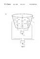
- FIG. 1is an isometric view of a multi-pattern antenna in accordance with a first embodiment of the invention
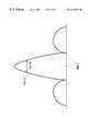
- FIG. 2shows antenna patterns generated by the multi-pattern antenna of FIG. 1;
- FIG. 3is an isometric view of a portion of a multi-pattern antenna in accordance with a second embodiment of the invention.
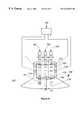
- FIG. 4is an isometric view of a multi-pattern antenna in accordance with a third embodiment of the invention.
- FIG. 5is a side view of a multi-pattern antenna coupled to a reflector in accordance with a fourth embodiment of the invention.
- FIG. 6shows antenna patterns generated by the multi-pattern antenna of FIG. 5;
- FIG. 7shows antenna patterns having approximately equivalent beamwidths
- FIG. 8is an isometric view of a multi-pattern antenna in accordance with a fifth embodiment of the invention.
- FIG. 9shows antenna patterns generated by the multi-pattern antenna of FIG. 8.
- FIG. 10is an isometric view of a dynamically adjustable multi-pattern antenna in accordance with a sixth embodiment of the present invention.
- the multi-pattern antenna 10for generating two antenna patterns 12 , 14 from a single compact structure is illustrated.
- the multi-pattern antenna 10can be configured to provide transmit only antenna patterns, receive only antenna patterns or a combination of transmit and receive antenna patterns.
- the present inventionwill be primarily explained for the transmit-only case.
- the antenna 10includes a horn 16 , a rod 18 , and, a conduit 20 where the conduit 20 surrounds a first portion of the rod 18 .
- the horn 16can be a conical horn, a corrugated horn, a square horn, an elliptical horn or any other horn type antenna known to one skilled in the art. A more detailed discussion of horn antennas can be found on pages in Chapter 7, at pp. 179-213 of Modern Antenna Design by Milligan.
- the multi-pattern antenna 10is adapted to receive a first 22 and a second 24 radio-frequency (RF) signal and is configured to couple the first 22 and second 24 RF signals into the antenna 10 .
- RFradio-frequency
- the first RF signal 22has a first frequency of operation and the second RF signal 24 has a second frequency of operation.
- the horn 18is configured and dimensioned to generate the first antenna pattern 12 from the first RF signal 22 .
- the characteristics of the first antenna pattern 12in particular the beamwidth 26 , is substantially determined by the configuration and dimensions of the horn 16 .
- the characteristics of the first antenna pattern 12are adjustable by adjusting the dimensions and configuration of the horn 16 .
- the first antenna pattern 12generated by the horn 16 , is approximately symmetrical in shape.
- the conduit 20is located within the horn 16 and is dimensioned to propagate the second RF signal 24 in a waveguide mode.
- the conduit 20is preferably cylindrical in shape and is positioned in approximately the center of the horn 16 so as to provide a smooth, symmetrical configuration to the first RF signal 22 , which is simultaneously propagating in the horn 16 , since a horn 18 , which is configured to be smooth and symmetrical generates a corresponding antenna pattern 12 , which is substantially symmetrically shaped.
- the conduit 20is configured to have a square, rectangular or oval cross-section or can be configured in any shape known in the art to propagate a RF signal 24 in a waveguide mode.
- the conduit 20can also be in the shape of a horn.
- the rod 18is positioned within the horn 16 with a first portion 28 of the rod 18 being located within the conduit 20 and a second portion 30 the rod 18 extending from the conduit 20 .
- the first 28 and second 30 portionstogether comprising the length of the rod 18 .
- the first portion 28 of the rod 18is responsive to the second RF signal 24 propagating in a waveguide mode within the conduit 20 .
- the first portion 28 of the rod 18is operative to transition the second RF signal 24 from propagating in a waveguide mode in the conduit 20 to propagating in a surface wave mode along the length of the rod 18 .
- the rod 18is configured with corrugations having dimensions which are preselected to transition the second RF signal 24 from a waveguide mode to a surface wave mode and propagate the second RF signal 24 along the length of the rod 18 in a surface wave mode.
- the exact dimensions of the rod 18are preselected with the aid of a computer program such as the ABKOR Program, which is commercially available through the University of Mississippi.
- the length of the conduit 20is selected to be of a preselected length to contain the second RF signal 24 within the conduit 20 until a sufficient amount of the second RF signal 24 has transitioned into a surface wave mode. It is preferred that the conduit 20 be long enough to contain the second RF signal 24 in a waveguide mode until at least 80% of the second RF signal 24 has transitioned from a waveguide mode into a surface wave mode to avoid incurring an undesirable amount of coupling between the first 22 and second 24 RF signals.
- the second RF signal 24propagates down the length of the rod 18 in a surface wave mode and radiates from the rod 18 .
- the second antenna pattern 14is generated from the radiated second RF signal 24 .
- the characteristics of the second antenna pattern 14is substantially determined by the dimensions, particularly the length, of the rod 18 which generated the second antenna pattern 14 . For example, a short rod 18 will generate an antenna pattern 14 having a broad beamwidth 32 whereas a long rod 18 will generate an antenna pattern 14 having a narrow beamwidth 32 .
- the actual dimensions of the rod 18 required to generate an antenna pattern 14 having preselected antenna pattern characteristicsis determined with the aid of the computer program mentioned above.
- the multi-pattern antenna 10provides two antenna patterns 12 , 14 from a single compact configuration where the pattern characteristics of each antenna pattern 12 , 14 is independently controllable.
- a plurality of openings 34are positioned at preselected locations on the wall of the horn 16 .
- the openings 34are preferably slots 34 which are adapted to receive the first RF signal 22 and are configured to couple the first RF signal 22 into the horn 16 .
- the number of slots 34 neededis dependent on the desired polarization of the first antenna pattern 12 which is subsequently generated from the first RF signal 22 .
- first antenna pattern 12which is circularly polarized requires four slots 34 which are positioned approximately 90 degrees apart from one another on the wall of the horn 16 . These slots 34 are used to couple the first RF signal 22 into the multi-pattern antenna 10 .
- a coupler 36is provided which is responsive to the first RF signal 22 and is operative to divide the first RF signal 22 into four intermediate RF signals 38 - 44 , preferably of approximately equal signal strengths.
- the coupler 36is also operative to phase delay the second 40 , third 42 , and fourth 44 intermediate signals by approximately 90 degrees, 180 degrees and 270 degrees respectfully with respect to the first intermediate signal 38 providing first 45 , second 47 and third 49 delayed signals from the second 40 , third 42 and fourth 44 intermediate signals, respectively.
- the coupler 36can be a hybrid coupler such as that commercially available by Millitech Corporation located in South Deerfield, Mass.
- the coupler 36can also be a plurality of Lange couplers or any other RF device known to one skilled in the art to divide an RF signal 22 into four intermediate signals 38 - 44 and phase delay the intermediate signals 38 - 44 a preselected amount with respect to each other.
- the first intermediate signal 38 and each delayed signal 40 - 44are coupled into the horn 16 through the slots 34 using coupling techniques which are well known in the art.
- the signals 38 - 44are coupled into the horn 16 in a preselected manner to provide a preselected phase progression so that the antenna pattern 12 generated from the first RF signal 22 will be either right or left-hand circularly polarized.
- to generate a linearly polarized antenna patternrequires only two slots 46 which are positioned ninety degrees apart on the wall of the horn 16 and a coupler 50 which divides the first RF signal 16 into two intermediate signals 52 , 54 and delays one intermediate signal 54 by ninety degrees with respect to the other intermediate signal 52 .
- the coupler 50can be a hybrid coupler such as that commercially available by Millitech Corporation located in South Deerfield, Mass., but can also be any RF device known to one skilled in the art to divide an RF signal 16 into two intermediate signals 50 , 54 and delay one of the intermediate signals 54 approximately ninety degrees with respect to the other intermediate signal 52 .
- the second RF signal 24is preferably coupled into the antenna through slots 60 positioned in the wall of the conduit 20 .
- the conduit 20is positioned so that a portion of the conduit 20 extends from the back 62 of the horn 16 and the slots 60 are located in the extended portion of the conduit 20 .
- the second RF signal 24is coupled into the conduit 24 through the slots 60 .
- the number of slots 60 needed to couple the second RF signal 24 into the conduit 20is dependent on the desired polarization of the second antenna pattern 14 which is subsequently generated from the second RF signal 24 .
- two slots 60 positioned ninety degrees apart from each other on the wall of the conduit 20are required to provide a second antenna pattern 14 which is circularly polarized.
- a coupler 64is operative to divide the second RF signal 24 into two intermediate signals 66 , 68 and delay one intermediate signal 68 by ninety degrees with respect to the other intermediate signal 66 .
- the intermediate signals 66 , 68are coupled into the slots 60 in a preselected manner which is known in the art to provide a right or left hand circularly polarized second antenna pattern 14 from the second RF signal 24 .
- to produce a linearly polarized second antenna pattern 14requires coupling the second RF signal 24 into the conduit 20 through a single slot 60 .
- the first 72 and the second 74 RF signalshave first and second frequency bands of operation, respectively, and are coupled into the antenna 76 through slots 78 , 80 , respectively, in the wall of the horn 82 in the manner described above.
- the dimensions of the horn 82are preselected so that the horn 82 propagates the first RF signal 72 but does not propagate the second RF signal 74 .
- the physical dimensions of the conduit 84are preselected to propagate an RF signal 74 having the second frequency band of operation and not propagate an RF signal having the first frequency band of operation such as the first RF signal 72 .
- the second RF signal 72couples into the conduit 84 through the top 86 of the conduit 84 and propagates in the conduit 84 in the manner described above, and the first RF signal 72 propagates in the horn 82 .
- the multi-pattern antenna 90is coupled to a reflector 92 and the first and second antenna patterns, depicted by the lines marked 94 & 96 , respectively, which are generated by the multi-pattern antenna 90 are configured as illumination patterns 94 , 96 which are positioned to illuminate the reflector 92 .
- the reflector 92 and multi-pattern antenna 90together comprise a multi-pattern reflector antenna 97 which is preferably mounted on a spacecraft (not shown) which is in orbit about the earth and is used to provide communications with the earth.
- the first 94 and second 96 illumination patternsare at frequencies of 20 GHz and 30 GHz, respectively, and the multi-pattern reflector antenna 97 is configured to provide up 100 and downlink 102 antenna patterns at frequencies of approximately 20 and 30 GHz from the first 94 and second 96 illumination patterns, respectively, where uplink antenna pattern 100 is a receive antenna pattern and the downlink antenna pattern 102 is a transmit antenna pattern.
- the horn 106 of the multi-pattern reflector antenna 97is configured to provide the downlink illumination pattern 94 and the rod 108 and conduit 110 are configured to provide the uplink illumination pattern 96 .
- the uplink 96 and downlink 94 illumination patternsare incident on the reflector 92 which generates therefrom the uplink 100 and downlink 102 antenna patterns, respectively.
- the pattern characteristics of the downlink antenna pattern 102are determined by the dimensions of the horn 106 as well as the configuration of the reflector 192 and can be altered by changing the dimensions of the horn 106
- the pattern characteristics of the uplink antenna pattern 100are determined by the dimensions of the rod 108 , particularly the rod length, and can be altered by changing the dimensions of the rod.
- the dimensions of the horn 106 and the dimensions of the rod 108are selected to provide uplink 120 and downlink 122 antenna patterns having approximately equivalent beamwidths 124 , 126 which enable users on the ground to both receive from and transmit to the same spacecraft.
- the dimensions and lengths of the rod 104 and the dimensions of the horn 106are preselected to provide the desired beamwidths 124 , 126 .
- the initial dimensions of the rod 108 and horn 106are determined with the aid of the above mentioned computer program.
- the pattern characteristicscan be easily adjusted after building and testing of the antenna 97 has been conducted since adjustments in the rod 108 has virtually no affect on the characteristics of the downlink antenna pattern 122 which is generated by the horn 106 and vice versa.
- the dimensions of the horn 106 and rod 108are preferably fixed prior to being placed on a spacecraft in order to provide antenna patterns 120 , 122 with predetermined fixed pattern characteristics.
- the multi-focus antenna 90has two phase centers 132 , 134 , one of which 132 is associated with the rod 108 and the other of which 134 is associated with the horn 106 .
- These phase centers 132 , 134are typically not co-located.
- the phase center 134 of the horn 106is co-located with the focal point 130 of the reflector 92 such that the downlink antenna pattern 102 which is generated by the horn 106 exhibits maximum efficiency.
- the multi-focus antenna 140generates a plurality of antenna patterns 142 - 147 and includes a horn 148 , a plurality of rods 150 - 154 and a plurality of conduits 156 - 160 with each conduit 156 - 160 surrounding a portion of one of the rods 150 - 154 , respectively.
- the multi-pattern antenna 140is adapted to receive a plurality of RF signals 162 - 168 , preferably each being at a different frequency of operation.
- the horn 148is configured and dimensioned to generate a first antenna pattern 142 from the first RF signal 162 in the manner described above, with the characteristics of the first antenna pattern 142 , in particular the beamwidth, being substantially determined by the configuration and dimensions of the horn 148 . As such, the characteristics of the first antenna pattern 142 are adjustable by adjusting the dimensions and configuration of the horn 148 .
- the conduits 156 - 160are located within the horn 148 .
- the dimensions of each conduit 156 - 160are configured to propagate one of the RF signals 164 - 168 , respectively, in a waveguide mode.
- the conduits 156 - 160can be cylindrical in shape, rectangle, square, or any other shape known in the art to propagate a RF signal in a waveguide mode.
- the conduits 156 - 160can also be horns.
- a large conduit 170is positioned around the smaller conduits 156 - 160 to provide a smooth, symmetrical configuration to the first RF signal 162 propagating within the horn 148 .
- a smooth, symmetrically configured horn 148will provide for a symmetrically shaped pattern from the first RF signal 162 .
- a rod 150 - 154is associated with each conduit 156 - 160 , respectively, with a first portion of each rod 150 - 154 being located within a conduit 156 - 160 and a second portion of each rod 150 - 154 extending from a conduit 156 - 160 , respectively.
- Each rod 150 - 154is responsive to the RF signal 164 - 168 propagating within the conduit 156 - 160 encompassing the rod 150 - 154 , respectively.
- Each rod 150 - 154is operative to transition one of the RF signals 164 - 168 , respectively, from the waveguide mode into a surface wave mode and propagates that RF signal 164 - 168 along the length of the rod 150 - 154 , respectively, in a surface wave mode.
- each rod 150 - 154is configured with corrugations having dimensions which are preselected to transition one RF signal 164 - 168 from a waveguide mode into a surface wave mode and propagate that RF signal 164 - 168 in a surface wave mode along the length of a rod 150 - 154 .
- the exact dimension of each rod 150 - 154is determined with the aid of a computer program such as the ABKOR Program mentioned above.
- each conduit 156 - 160is selected to be of a sufficient length to contain one of the RF signal 164 - 168 , respectively, within a conduit 156 - 160 until a sufficient amount of each RF signal 164 - 168 has transitioned into a surface wave mode.
- Each rod 150 - 154is configured to generate an antenna pattern 144 - 148 from the RF signal 164 - 168 propagating down the respective rod 150 - 156 .
- the characteristics of each antenna pattern 144 - 147is substantially determined by the dimensions, particularly the length, of the rod 150 - 156 generating the respective antenna pattern 144 - 147 .
- a short rod 150will generate an antenna pattern 144 having a broader beamwidth than the beamwidth of an antenna pattern 146 generated by a longer rod 152 .
- the actual dimensions of each rod 150 - 156 required to generate an antenna pattern 144 - 147 , respectively, having preselected antenna pattern characteristicsis determined with the aid of the computer program mentioned above.
- each rod 150 - 156changes the characteristics of the antenna pattern 144 - 147 generated by that rod, a change in the dimensions of a rod 150 - 156 has little to no effect on the pattern characteristics of the antenna pattern 142 generated by the horn 148 .
- changing the dimensions of the horn 148 in order to change the pattern characteristics of the antenna pattern 142 generated by the horn 148has little to no effect on the pattern characteristics of the antenna patterns 144 - 147 generated by the rods 150 - 154 .
- changes in the length of one rod 150has little to no effect on the pattern characteristics of an antenna pattern 146 generated by another one of the rods 152 .
- the antenna 140provides multiple antenna patterns 142 - 147 from a single compact configuration where the pattern characteristics of each antenna pattern 142 - 147 is independently controllable.
- each rod 200 - 204 of the multi-pattern antenna 206is responsive to a control signal 208 - 212 , respectively, and is operative to dynamically adjust the portion of each rod 200 - 204 which extends from the conduits 216 - 220 into the horn 214 .
- each rod 200 - 204is initially configured with an extra amount of length 221 - 224 which is positioned to extend out the back of the conduits 216 - 220 .
- Each rod 200 - 204is attached to a mechanism (not shown) which is operative to move each rod 200 - 204 into and out of the horn 214 in the direction indicated by the arrows 226 - 230 to extend a larger or smaller portion of each rod 200 - 204 out of the conduits 216 - 220 and into the horn 214 .
- the characteristics of each antenna pattern generated by a rod 200 - 204is determined by the length of the portion of the rod 200 - 204 which extends from the conduits 216 - 220 into the horn 214 .
- Changing the length of the portion of a rod 200 - 204 which extends from a conduit 216 - 220 , respectively, into the horn 214changes the characteristics of the antenna pattern generated by that rod 200 - 204 .
- Making the rods 200 - 204 responsive to a control signal 208 - 212provides an antenna 206 having dynamically controllable antenna pattern characteristics.
- the control signals 208 - 212would preferably originate on the earth but could also be generated by the electronics (not shown) on the spacecraft upon which the multi-pattern antenna 206 could be mounted.
- the dynamically adjustable multi-pattern antenna 206can be used alone or coupled with a reflector (not shown) as previously described.
- the dynamically adjustable multi-pattern antenna 206is particularly useful in spacecraft applications where a broad beamwidth antenna pattern is required at a preselected time, and, a narrow beamwidth, higher gain antenna pattern at the same frequency is required at another time.
- the first rod 200could be configured to generate an antenna pattern having a broad beamwidth, such as an 8.7 degree beamwidth, which would cover the entire earth from a spacecraft in a geosynchronous orbit.
- a control signal 208would be received by the first rod 200 and the portion of the rod 200 which extends into the horn 214 would be extended in length in response to the control signal 208 .
- antenna patterns having dynamically controllable pattern characteristicscan be generated from a single structure.
Landscapes
- Physics & Mathematics (AREA)
- Electromagnetism (AREA)
- Waveguide Aerials (AREA)
- Variable-Direction Aerials And Aerial Arrays (AREA)
- Aerials With Secondary Devices (AREA)
- Waveguide Switches, Polarizers, And Phase Shifters (AREA)
Abstract
Description
Claims (19)
Priority Applications (4)
| Application Number | Priority Date | Filing Date | Title |
|---|---|---|---|
| US09/405,765US6243049B1 (en) | 1999-09-27 | 1999-09-27 | Multi-pattern antenna having independently controllable antenna pattern characteristics |
| CA002316783ACA2316783C (en) | 1999-09-27 | 2000-08-28 | A multi-pattern antenna having independently controllable antenna pattern characteristics |
| EP00118184AEP1087463A3 (en) | 1999-09-27 | 2000-08-30 | A multi-pattern antenna having independent controllable antenna pattern characteristics |
| JP2000291744AJP3444850B2 (en) | 1999-09-27 | 2000-09-26 | Multi-pattern antenna with independently controllable antenna pattern characteristics |
Applications Claiming Priority (1)
| Application Number | Priority Date | Filing Date | Title |
|---|---|---|---|
| US09/405,765US6243049B1 (en) | 1999-09-27 | 1999-09-27 | Multi-pattern antenna having independently controllable antenna pattern characteristics |
Publications (1)
| Publication Number | Publication Date |
|---|---|
| US6243049B1true US6243049B1 (en) | 2001-06-05 |
Family
ID=23605136
Family Applications (1)
| Application Number | Title | Priority Date | Filing Date |
|---|---|---|---|
| US09/405,765Expired - Fee RelatedUS6243049B1 (en) | 1999-09-27 | 1999-09-27 | Multi-pattern antenna having independently controllable antenna pattern characteristics |
Country Status (4)
| Country | Link |
|---|---|
| US (1) | US6243049B1 (en) |
| EP (1) | EP1087463A3 (en) |
| JP (1) | JP3444850B2 (en) |
| CA (1) | CA2316783C (en) |
Cited By (143)
| Publication number | Priority date | Publication date | Assignee | Title |
|---|---|---|---|---|
| US20030218973A1 (en)* | 2002-05-24 | 2003-11-27 | Oprea Alexandru M. | System and method for data detection in wireless communication systems |
| US7327795B2 (en) | 2003-03-31 | 2008-02-05 | Vecima Networks Inc. | System and method for wireless communication systems |
| US9608740B2 (en) | 2015-07-15 | 2017-03-28 | At&T Intellectual Property I, L.P. | Method and apparatus for launching a wave mode that mitigates interference |
| US9615269B2 (en) | 2014-10-02 | 2017-04-04 | At&T Intellectual Property I, L.P. | Method and apparatus that provides fault tolerance in a communication network |
| US9640850B2 (en) | 2015-06-25 | 2017-05-02 | At&T Intellectual Property I, L.P. | Methods and apparatus for inducing a non-fundamental wave mode on a transmission medium |
| US9667317B2 (en) | 2015-06-15 | 2017-05-30 | At&T Intellectual Property I, L.P. | Method and apparatus for providing security using network traffic adjustments |
| US9674711B2 (en) | 2013-11-06 | 2017-06-06 | At&T Intellectual Property I, L.P. | Surface-wave communications and methods thereof |
| US9685992B2 (en) | 2014-10-03 | 2017-06-20 | At&T Intellectual Property I, L.P. | Circuit panel network and methods thereof |
| US9699785B2 (en) | 2012-12-05 | 2017-07-04 | At&T Intellectual Property I, L.P. | Backhaul link for distributed antenna system |
| US9705561B2 (en) | 2015-04-24 | 2017-07-11 | At&T Intellectual Property I, L.P. | Directional coupling device and methods for use therewith |
| US9705610B2 (en) | 2014-10-21 | 2017-07-11 | At&T Intellectual Property I, L.P. | Transmission device with impairment compensation and methods for use therewith |
| US9722318B2 (en) | 2015-07-14 | 2017-08-01 | At&T Intellectual Property I, L.P. | Method and apparatus for coupling an antenna to a device |
| US9729197B2 (en) | 2015-10-01 | 2017-08-08 | At&T Intellectual Property I, L.P. | Method and apparatus for communicating network management traffic over a network |
| US9735833B2 (en) | 2015-07-31 | 2017-08-15 | At&T Intellectual Property I, L.P. | Method and apparatus for communications management in a neighborhood network |
| US9742462B2 (en) | 2014-12-04 | 2017-08-22 | At&T Intellectual Property I, L.P. | Transmission medium and communication interfaces and methods for use therewith |
| US9742521B2 (en) | 2014-11-20 | 2017-08-22 | At&T Intellectual Property I, L.P. | Transmission device with mode division multiplexing and methods for use therewith |
| US9749053B2 (en) | 2015-07-23 | 2017-08-29 | At&T Intellectual Property I, L.P. | Node device, repeater and methods for use therewith |
| US9748626B2 (en) | 2015-05-14 | 2017-08-29 | At&T Intellectual Property I, L.P. | Plurality of cables having different cross-sectional shapes which are bundled together to form a transmission medium |
| US9749013B2 (en) | 2015-03-17 | 2017-08-29 | At&T Intellectual Property I, L.P. | Method and apparatus for reducing attenuation of electromagnetic waves guided by a transmission medium |
| US9762289B2 (en) | 2014-10-14 | 2017-09-12 | At&T Intellectual Property I, L.P. | Method and apparatus for transmitting or receiving signals in a transportation system |
| US9769128B2 (en) | 2015-09-28 | 2017-09-19 | At&T Intellectual Property I, L.P. | Method and apparatus for encryption of communications over a network |
| US9768833B2 (en) | 2014-09-15 | 2017-09-19 | At&T Intellectual Property I, L.P. | Method and apparatus for sensing a condition in a transmission medium of electromagnetic waves |
| US9769020B2 (en) | 2014-10-21 | 2017-09-19 | At&T Intellectual Property I, L.P. | Method and apparatus for responding to events affecting communications in a communication network |
| US9780834B2 (en) | 2014-10-21 | 2017-10-03 | At&T Intellectual Property I, L.P. | Method and apparatus for transmitting electromagnetic waves |
| US9787412B2 (en) | 2015-06-25 | 2017-10-10 | At&T Intellectual Property I, L.P. | Methods and apparatus for inducing a fundamental wave mode on a transmission medium |
| US9793951B2 (en) | 2015-07-15 | 2017-10-17 | At&T Intellectual Property I, L.P. | Method and apparatus for launching a wave mode that mitigates interference |
| US9793955B2 (en) | 2015-04-24 | 2017-10-17 | At&T Intellectual Property I, Lp | Passive electrical coupling device and methods for use therewith |
| US9793954B2 (en) | 2015-04-28 | 2017-10-17 | At&T Intellectual Property I, L.P. | Magnetic coupling device and methods for use therewith |
| US9800327B2 (en) | 2014-11-20 | 2017-10-24 | At&T Intellectual Property I, L.P. | Apparatus for controlling operations of a communication device and methods thereof |
| US9820146B2 (en) | 2015-06-12 | 2017-11-14 | At&T Intellectual Property I, L.P. | Method and apparatus for authentication and identity management of communicating devices |
| US9838078B2 (en) | 2015-07-31 | 2017-12-05 | At&T Intellectual Property I, L.P. | Method and apparatus for exchanging communication signals |
| US9838896B1 (en) | 2016-12-09 | 2017-12-05 | At&T Intellectual Property I, L.P. | Method and apparatus for assessing network coverage |
| US9847850B2 (en) | 2014-10-14 | 2017-12-19 | At&T Intellectual Property I, L.P. | Method and apparatus for adjusting a mode of communication in a communication network |
| US9847566B2 (en) | 2015-07-14 | 2017-12-19 | At&T Intellectual Property I, L.P. | Method and apparatus for adjusting a field of a signal to mitigate interference |
| US9853342B2 (en) | 2015-07-14 | 2017-12-26 | At&T Intellectual Property I, L.P. | Dielectric transmission medium connector and methods for use therewith |
| US9860075B1 (en) | 2016-08-26 | 2018-01-02 | At&T Intellectual Property I, L.P. | Method and communication node for broadband distribution |
| US9866276B2 (en) | 2014-10-10 | 2018-01-09 | At&T Intellectual Property I, L.P. | Method and apparatus for arranging communication sessions in a communication system |
| US9865911B2 (en)* | 2015-06-25 | 2018-01-09 | At&T Intellectual Property I, L.P. | Waveguide system for slot radiating first electromagnetic waves that are combined into a non-fundamental wave mode second electromagnetic wave on a transmission medium |
| US9866309B2 (en) | 2015-06-03 | 2018-01-09 | At&T Intellectual Property I, Lp | Host node device and methods for use therewith |
| US9871283B2 (en) | 2015-07-23 | 2018-01-16 | At&T Intellectual Property I, Lp | Transmission medium having a dielectric core comprised of plural members connected by a ball and socket configuration |
| US9871558B2 (en) | 2014-10-21 | 2018-01-16 | At&T Intellectual Property I, L.P. | Guided-wave transmission device and methods for use therewith |
| US9871282B2 (en) | 2015-05-14 | 2018-01-16 | At&T Intellectual Property I, L.P. | At least one transmission medium having a dielectric surface that is covered at least in part by a second dielectric |
| US9876570B2 (en) | 2015-02-20 | 2018-01-23 | At&T Intellectual Property I, Lp | Guided-wave transmission device with non-fundamental mode propagation and methods for use therewith |
| US9876605B1 (en) | 2016-10-21 | 2018-01-23 | At&T Intellectual Property I, L.P. | Launcher and coupling system to support desired guided wave mode |
| US9876264B2 (en) | 2015-10-02 | 2018-01-23 | At&T Intellectual Property I, Lp | Communication system, guided wave switch and methods for use therewith |
| US9882257B2 (en) | 2015-07-14 | 2018-01-30 | At&T Intellectual Property I, L.P. | Method and apparatus for launching a wave mode that mitigates interference |
| US9887447B2 (en) | 2015-05-14 | 2018-02-06 | At&T Intellectual Property I, L.P. | Transmission medium having multiple cores and methods for use therewith |
| US9893795B1 (en) | 2016-12-07 | 2018-02-13 | At&T Intellectual Property I, Lp | Method and repeater for broadband distribution |
| US9906269B2 (en) | 2014-09-17 | 2018-02-27 | At&T Intellectual Property I, L.P. | Monitoring and mitigating conditions in a communication network |
| US9904535B2 (en) | 2015-09-14 | 2018-02-27 | At&T Intellectual Property I, L.P. | Method and apparatus for distributing software |
| US9913139B2 (en) | 2015-06-09 | 2018-03-06 | At&T Intellectual Property I, L.P. | Signal fingerprinting for authentication of communicating devices |
| US9912382B2 (en) | 2015-06-03 | 2018-03-06 | At&T Intellectual Property I, Lp | Network termination and methods for use therewith |
| US9911020B1 (en) | 2016-12-08 | 2018-03-06 | At&T Intellectual Property I, L.P. | Method and apparatus for tracking via a radio frequency identification device |
| US9912033B2 (en) | 2014-10-21 | 2018-03-06 | At&T Intellectual Property I, Lp | Guided wave coupler, coupling module and methods for use therewith |
| US9912027B2 (en) | 2015-07-23 | 2018-03-06 | At&T Intellectual Property I, L.P. | Method and apparatus for exchanging communication signals |
| US9912419B1 (en) | 2016-08-24 | 2018-03-06 | At&T Intellectual Property I, L.P. | Method and apparatus for managing a fault in a distributed antenna system |
| US9917341B2 (en) | 2015-05-27 | 2018-03-13 | At&T Intellectual Property I, L.P. | Apparatus and method for launching electromagnetic waves and for modifying radial dimensions of the propagating electromagnetic waves |
| US9930668B2 (en) | 2013-05-31 | 2018-03-27 | At&T Intellectual Property I, L.P. | Remote distributed antenna system |
| US9929755B2 (en) | 2015-07-14 | 2018-03-27 | At&T Intellectual Property I, L.P. | Method and apparatus for coupling an antenna to a device |
| US9927517B1 (en) | 2016-12-06 | 2018-03-27 | At&T Intellectual Property I, L.P. | Apparatus and methods for sensing rainfall |
| US9948354B2 (en) | 2015-04-28 | 2018-04-17 | At&T Intellectual Property I, L.P. | Magnetic coupling device with reflective plate and methods for use therewith |
| US9948333B2 (en) | 2015-07-23 | 2018-04-17 | At&T Intellectual Property I, L.P. | Method and apparatus for wireless communications to mitigate interference |
| US9948355B2 (en) | 2014-10-21 | 2018-04-17 | At&T Intellectual Property I, L.P. | Apparatus for providing communication services and methods thereof |
| US9954286B2 (en) | 2014-10-21 | 2018-04-24 | At&T Intellectual Property I, L.P. | Guided-wave transmission device with non-fundamental mode propagation and methods for use therewith |
| US9954287B2 (en) | 2014-11-20 | 2018-04-24 | At&T Intellectual Property I, L.P. | Apparatus for converting wireless signals and electromagnetic waves and methods thereof |
| US9967173B2 (en) | 2015-07-31 | 2018-05-08 | At&T Intellectual Property I, L.P. | Method and apparatus for authentication and identity management of communicating devices |
| US9973940B1 (en) | 2017-02-27 | 2018-05-15 | At&T Intellectual Property I, L.P. | Apparatus and methods for dynamic impedance matching of a guided wave launcher |
| US9991580B2 (en) | 2016-10-21 | 2018-06-05 | At&T Intellectual Property I, L.P. | Launcher and coupling system for guided wave mode cancellation |
| US9998870B1 (en) | 2016-12-08 | 2018-06-12 | At&T Intellectual Property I, L.P. | Method and apparatus for proximity sensing |
| US9997819B2 (en) | 2015-06-09 | 2018-06-12 | At&T Intellectual Property I, L.P. | Transmission medium and method for facilitating propagation of electromagnetic waves via a core |
| US9999038B2 (en) | 2013-05-31 | 2018-06-12 | At&T Intellectual Property I, L.P. | Remote distributed antenna system |
| US10009063B2 (en) | 2015-09-16 | 2018-06-26 | At&T Intellectual Property I, L.P. | Method and apparatus for use with a radio distributed antenna system having an out-of-band reference signal |
| US10009067B2 (en) | 2014-12-04 | 2018-06-26 | At&T Intellectual Property I, L.P. | Method and apparatus for configuring a communication interface |
| US10020844B2 (en) | 2016-12-06 | 2018-07-10 | T&T Intellectual Property I, L.P. | Method and apparatus for broadcast communication via guided waves |
| US10027398B2 (en) | 2015-06-11 | 2018-07-17 | At&T Intellectual Property I, Lp | Repeater and methods for use therewith |
| US10027397B2 (en) | 2016-12-07 | 2018-07-17 | At&T Intellectual Property I, L.P. | Distributed antenna system and methods for use therewith |
| US10033108B2 (en) | 2015-07-14 | 2018-07-24 | At&T Intellectual Property I, L.P. | Apparatus and methods for generating an electromagnetic wave having a wave mode that mitigates interference |
| US10044409B2 (en) | 2015-07-14 | 2018-08-07 | At&T Intellectual Property I, L.P. | Transmission medium and methods for use therewith |
| US10069535B2 (en) | 2016-12-08 | 2018-09-04 | At&T Intellectual Property I, L.P. | Apparatus and methods for launching electromagnetic waves having a certain electric field structure |
| US10079661B2 (en) | 2015-09-16 | 2018-09-18 | At&T Intellectual Property I, L.P. | Method and apparatus for use with a radio distributed antenna system having a clock reference |
| US10090606B2 (en) | 2015-07-15 | 2018-10-02 | At&T Intellectual Property I, L.P. | Antenna system with dielectric array and methods for use therewith |
| US10090594B2 (en) | 2016-11-23 | 2018-10-02 | At&T Intellectual Property I, L.P. | Antenna system having structural configurations for assembly |
| US10103422B2 (en) | 2016-12-08 | 2018-10-16 | At&T Intellectual Property I, L.P. | Method and apparatus for mounting network devices |
| US10103801B2 (en) | 2015-06-03 | 2018-10-16 | At&T Intellectual Property I, L.P. | Host node device and methods for use therewith |
| US10135145B2 (en) | 2016-12-06 | 2018-11-20 | At&T Intellectual Property I, L.P. | Apparatus and methods for generating an electromagnetic wave along a transmission medium |
| US10136434B2 (en) | 2015-09-16 | 2018-11-20 | At&T Intellectual Property I, L.P. | Method and apparatus for use with a radio distributed antenna system having an ultra-wideband control channel |
| US10135147B2 (en) | 2016-10-18 | 2018-11-20 | At&T Intellectual Property I, L.P. | Apparatus and methods for launching guided waves via an antenna |
| US10135146B2 (en) | 2016-10-18 | 2018-11-20 | At&T Intellectual Property I, L.P. | Apparatus and methods for launching guided waves via circuits |
| US10139820B2 (en) | 2016-12-07 | 2018-11-27 | At&T Intellectual Property I, L.P. | Method and apparatus for deploying equipment of a communication system |
| US10142086B2 (en) | 2015-06-11 | 2018-11-27 | At&T Intellectual Property I, L.P. | Repeater and methods for use therewith |
| US10144036B2 (en) | 2015-01-30 | 2018-12-04 | At&T Intellectual Property I, L.P. | Method and apparatus for mitigating interference affecting a propagation of electromagnetic waves guided by a transmission medium |
| US10148016B2 (en) | 2015-07-14 | 2018-12-04 | At&T Intellectual Property I, L.P. | Apparatus and methods for communicating utilizing an antenna array |
| US10170840B2 (en) | 2015-07-14 | 2019-01-01 | At&T Intellectual Property I, L.P. | Apparatus and methods for sending or receiving electromagnetic signals |
| US10168695B2 (en) | 2016-12-07 | 2019-01-01 | At&T Intellectual Property I, L.P. | Method and apparatus for controlling an unmanned aircraft |
| US10178445B2 (en) | 2016-11-23 | 2019-01-08 | At&T Intellectual Property I, L.P. | Methods, devices, and systems for load balancing between a plurality of waveguides |
| US10205655B2 (en) | 2015-07-14 | 2019-02-12 | At&T Intellectual Property I, L.P. | Apparatus and methods for communicating utilizing an antenna array and multiple communication paths |
| US10225025B2 (en) | 2016-11-03 | 2019-03-05 | At&T Intellectual Property I, L.P. | Method and apparatus for detecting a fault in a communication system |
| US10224634B2 (en) | 2016-11-03 | 2019-03-05 | At&T Intellectual Property I, L.P. | Methods and apparatus for adjusting an operational characteristic of an antenna |
| US10243270B2 (en) | 2016-12-07 | 2019-03-26 | At&T Intellectual Property I, L.P. | Beam adaptive multi-feed dielectric antenna system and methods for use therewith |
| US10243784B2 (en) | 2014-11-20 | 2019-03-26 | At&T Intellectual Property I, L.P. | System for generating topology information and methods thereof |
| US10264586B2 (en) | 2016-12-09 | 2019-04-16 | At&T Mobility Ii Llc | Cloud-based packet controller and methods for use therewith |
| US10291311B2 (en) | 2016-09-09 | 2019-05-14 | At&T Intellectual Property I, L.P. | Method and apparatus for mitigating a fault in a distributed antenna system |
| US10291334B2 (en) | 2016-11-03 | 2019-05-14 | At&T Intellectual Property I, L.P. | System for detecting a fault in a communication system |
| US10298293B2 (en) | 2017-03-13 | 2019-05-21 | At&T Intellectual Property I, L.P. | Apparatus of communication utilizing wireless network devices |
| US10305190B2 (en) | 2016-12-01 | 2019-05-28 | At&T Intellectual Property I, L.P. | Reflecting dielectric antenna system and methods for use therewith |
| US10312567B2 (en) | 2016-10-26 | 2019-06-04 | At&T Intellectual Property I, L.P. | Launcher with planar strip antenna and methods for use therewith |
| US10320586B2 (en) | 2015-07-14 | 2019-06-11 | At&T Intellectual Property I, L.P. | Apparatus and methods for generating non-interfering electromagnetic waves on an insulated transmission medium |
| US10326689B2 (en) | 2016-12-08 | 2019-06-18 | At&T Intellectual Property I, L.P. | Method and system for providing alternative communication paths |
| US10326494B2 (en) | 2016-12-06 | 2019-06-18 | At&T Intellectual Property I, L.P. | Apparatus for measurement de-embedding and methods for use therewith |
| US10340601B2 (en) | 2016-11-23 | 2019-07-02 | At&T Intellectual Property I, L.P. | Multi-antenna system and methods for use therewith |
| US10340600B2 (en) | 2016-10-18 | 2019-07-02 | At&T Intellectual Property I, L.P. | Apparatus and methods for launching guided waves via plural waveguide systems |
| US10341142B2 (en) | 2015-07-14 | 2019-07-02 | At&T Intellectual Property I, L.P. | Apparatus and methods for generating non-interfering electromagnetic waves on an uninsulated conductor |
| US10340573B2 (en) | 2016-10-26 | 2019-07-02 | At&T Intellectual Property I, L.P. | Launcher with cylindrical coupling device and methods for use therewith |
| US10340603B2 (en) | 2016-11-23 | 2019-07-02 | At&T Intellectual Property I, L.P. | Antenna system having shielded structural configurations for assembly |
| US10340983B2 (en) | 2016-12-09 | 2019-07-02 | At&T Intellectual Property I, L.P. | Method and apparatus for surveying remote sites via guided wave communications |
| US10355367B2 (en) | 2015-10-16 | 2019-07-16 | At&T Intellectual Property I, L.P. | Antenna structure for exchanging wireless signals |
| US10361489B2 (en) | 2016-12-01 | 2019-07-23 | At&T Intellectual Property I, L.P. | Dielectric dish antenna system and methods for use therewith |
| US10359749B2 (en) | 2016-12-07 | 2019-07-23 | At&T Intellectual Property I, L.P. | Method and apparatus for utilities management via guided wave communication |
| US10374316B2 (en) | 2016-10-21 | 2019-08-06 | At&T Intellectual Property I, L.P. | System and dielectric antenna with non-uniform dielectric |
| US10382976B2 (en) | 2016-12-06 | 2019-08-13 | At&T Intellectual Property I, L.P. | Method and apparatus for managing wireless communications based on communication paths and network device positions |
| US10389029B2 (en) | 2016-12-07 | 2019-08-20 | At&T Intellectual Property I, L.P. | Multi-feed dielectric antenna system with core selection and methods for use therewith |
| US10389037B2 (en) | 2016-12-08 | 2019-08-20 | At&T Intellectual Property I, L.P. | Apparatus and methods for selecting sections of an antenna array and use therewith |
| US10411356B2 (en) | 2016-12-08 | 2019-09-10 | At&T Intellectual Property I, L.P. | Apparatus and methods for selectively targeting communication devices with an antenna array |
| US10439675B2 (en) | 2016-12-06 | 2019-10-08 | At&T Intellectual Property I, L.P. | Method and apparatus for repeating guided wave communication signals |
| US10446936B2 (en) | 2016-12-07 | 2019-10-15 | At&T Intellectual Property I, L.P. | Multi-feed dielectric antenna system and methods for use therewith |
| US10498044B2 (en) | 2016-11-03 | 2019-12-03 | At&T Intellectual Property I, L.P. | Apparatus for configuring a surface of an antenna |
| US10530505B2 (en) | 2016-12-08 | 2020-01-07 | At&T Intellectual Property I, L.P. | Apparatus and methods for launching electromagnetic waves along a transmission medium |
| US10535928B2 (en) | 2016-11-23 | 2020-01-14 | At&T Intellectual Property I, L.P. | Antenna system and methods for use therewith |
| US10547348B2 (en) | 2016-12-07 | 2020-01-28 | At&T Intellectual Property I, L.P. | Method and apparatus for switching transmission mediums in a communication system |
| US10601494B2 (en) | 2016-12-08 | 2020-03-24 | At&T Intellectual Property I, L.P. | Dual-band communication device and method for use therewith |
| US10637149B2 (en) | 2016-12-06 | 2020-04-28 | At&T Intellectual Property I, L.P. | Injection molded dielectric antenna and methods for use therewith |
| US10650940B2 (en) | 2015-05-15 | 2020-05-12 | At&T Intellectual Property I, L.P. | Transmission medium having a conductive material and methods for use therewith |
| US10694379B2 (en) | 2016-12-06 | 2020-06-23 | At&T Intellectual Property I, L.P. | Waveguide system with device-based authentication and methods for use therewith |
| US10727599B2 (en) | 2016-12-06 | 2020-07-28 | At&T Intellectual Property I, L.P. | Launcher with slot antenna and methods for use therewith |
| US10755542B2 (en) | 2016-12-06 | 2020-08-25 | At&T Intellectual Property I, L.P. | Method and apparatus for surveillance via guided wave communication |
| US10777873B2 (en) | 2016-12-08 | 2020-09-15 | At&T Intellectual Property I, L.P. | Method and apparatus for mounting network devices |
| US10797781B2 (en) | 2015-06-03 | 2020-10-06 | At&T Intellectual Property I, L.P. | Client node device and methods for use therewith |
| US10811767B2 (en) | 2016-10-21 | 2020-10-20 | At&T Intellectual Property I, L.P. | System and dielectric antenna with convex dielectric radome |
| US10819035B2 (en) | 2016-12-06 | 2020-10-27 | At&T Intellectual Property I, L.P. | Launcher with helical antenna and methods for use therewith |
| US10916969B2 (en) | 2016-12-08 | 2021-02-09 | At&T Intellectual Property I, L.P. | Method and apparatus for providing power using an inductive coupling |
| US10938108B2 (en) | 2016-12-08 | 2021-03-02 | At&T Intellectual Property I, L.P. | Frequency selective multi-feed dielectric antenna system and methods for use therewith |
| US11032819B2 (en) | 2016-09-15 | 2021-06-08 | At&T Intellectual Property I, L.P. | Method and apparatus for use with a radio distributed antenna system having a control channel reference signal |
| US11411326B2 (en) | 2020-06-04 | 2022-08-09 | City University Of Hong Kong | Broadbeam dielectric resonator antenna |
Families Citing this family (2)
| Publication number | Priority date | Publication date | Assignee | Title |
|---|---|---|---|---|
| US7110716B2 (en)* | 2002-01-30 | 2006-09-19 | The Boeing Company | Dual-band multiple beam antenna system for communication satellites |
| US9577341B2 (en) | 2013-11-12 | 2017-02-21 | Harris Corporation | Microcellular communications antenna and associated methods |
Citations (5)
| Publication number | Priority date | Publication date | Assignee | Title |
|---|---|---|---|---|
| US4489331A (en)* | 1981-01-23 | 1984-12-18 | Thomson-Csf | Two-band microwave antenna with nested horns for feeding a sub and main reflector |
| USH584H (en)* | 1986-12-18 | 1989-02-07 | The United States Of America As Represented By The Secretary Of The Army | Dielectric omni-directional antennas |
| US5038151A (en)* | 1989-07-31 | 1991-08-06 | Loral Aerospace Corp. | Simultaneous transmit and receive antenna |
| US5041840A (en)* | 1987-04-13 | 1991-08-20 | Frank Cipolla | Multiple frequency antenna feed |
| US5109232A (en)* | 1990-02-20 | 1992-04-28 | Andrew Corporation | Dual frequency antenna feed with apertured channel |
Family Cites Families (2)
| Publication number | Priority date | Publication date | Assignee | Title |
|---|---|---|---|---|
| US2663797A (en)* | 1949-05-05 | 1953-12-22 | Bell Telephone Labor Inc | Directive antenna |
| US5003321A (en)* | 1985-09-09 | 1991-03-26 | Sts Enterprises, Inc. | Dual frequency feed |
- 1999
- 1999-09-27USUS09/405,765patent/US6243049B1/ennot_activeExpired - Fee Related
- 2000
- 2000-08-28CACA002316783Apatent/CA2316783C/ennot_activeExpired - Fee Related
- 2000-08-30EPEP00118184Apatent/EP1087463A3/ennot_activeWithdrawn
- 2000-09-26JPJP2000291744Apatent/JP3444850B2/ennot_activeExpired - Fee Related
Patent Citations (5)
| Publication number | Priority date | Publication date | Assignee | Title |
|---|---|---|---|---|
| US4489331A (en)* | 1981-01-23 | 1984-12-18 | Thomson-Csf | Two-band microwave antenna with nested horns for feeding a sub and main reflector |
| USH584H (en)* | 1986-12-18 | 1989-02-07 | The United States Of America As Represented By The Secretary Of The Army | Dielectric omni-directional antennas |
| US5041840A (en)* | 1987-04-13 | 1991-08-20 | Frank Cipolla | Multiple frequency antenna feed |
| US5038151A (en)* | 1989-07-31 | 1991-08-06 | Loral Aerospace Corp. | Simultaneous transmit and receive antenna |
| US5109232A (en)* | 1990-02-20 | 1992-04-28 | Andrew Corporation | Dual frequency antenna feed with apertured channel |
Non-Patent Citations (1)
| Title |
|---|
| Modern Antenna Design, Milligan pp. 179-213, Chapter 7. |
Cited By (167)
| Publication number | Priority date | Publication date | Assignee | Title |
|---|---|---|---|---|
| US20030218973A1 (en)* | 2002-05-24 | 2003-11-27 | Oprea Alexandru M. | System and method for data detection in wireless communication systems |
| US7327800B2 (en) | 2002-05-24 | 2008-02-05 | Vecima Networks Inc. | System and method for data detection in wireless communication systems |
| US7327795B2 (en) | 2003-03-31 | 2008-02-05 | Vecima Networks Inc. | System and method for wireless communication systems |
| US9699785B2 (en) | 2012-12-05 | 2017-07-04 | At&T Intellectual Property I, L.P. | Backhaul link for distributed antenna system |
| US9788326B2 (en) | 2012-12-05 | 2017-10-10 | At&T Intellectual Property I, L.P. | Backhaul link for distributed antenna system |
| US10194437B2 (en) | 2012-12-05 | 2019-01-29 | At&T Intellectual Property I, L.P. | Backhaul link for distributed antenna system |
| US10051630B2 (en) | 2013-05-31 | 2018-08-14 | At&T Intellectual Property I, L.P. | Remote distributed antenna system |
| US9930668B2 (en) | 2013-05-31 | 2018-03-27 | At&T Intellectual Property I, L.P. | Remote distributed antenna system |
| US10091787B2 (en) | 2013-05-31 | 2018-10-02 | At&T Intellectual Property I, L.P. | Remote distributed antenna system |
| US9999038B2 (en) | 2013-05-31 | 2018-06-12 | At&T Intellectual Property I, L.P. | Remote distributed antenna system |
| US9674711B2 (en) | 2013-11-06 | 2017-06-06 | At&T Intellectual Property I, L.P. | Surface-wave communications and methods thereof |
| US9768833B2 (en) | 2014-09-15 | 2017-09-19 | At&T Intellectual Property I, L.P. | Method and apparatus for sensing a condition in a transmission medium of electromagnetic waves |
| US10063280B2 (en) | 2014-09-17 | 2018-08-28 | At&T Intellectual Property I, L.P. | Monitoring and mitigating conditions in a communication network |
| US9906269B2 (en) | 2014-09-17 | 2018-02-27 | At&T Intellectual Property I, L.P. | Monitoring and mitigating conditions in a communication network |
| US9973416B2 (en) | 2014-10-02 | 2018-05-15 | At&T Intellectual Property I, L.P. | Method and apparatus that provides fault tolerance in a communication network |
| US9615269B2 (en) | 2014-10-02 | 2017-04-04 | At&T Intellectual Property I, L.P. | Method and apparatus that provides fault tolerance in a communication network |
| US9685992B2 (en) | 2014-10-03 | 2017-06-20 | At&T Intellectual Property I, L.P. | Circuit panel network and methods thereof |
| US9866276B2 (en) | 2014-10-10 | 2018-01-09 | At&T Intellectual Property I, L.P. | Method and apparatus for arranging communication sessions in a communication system |
| US9762289B2 (en) | 2014-10-14 | 2017-09-12 | At&T Intellectual Property I, L.P. | Method and apparatus for transmitting or receiving signals in a transportation system |
| US9847850B2 (en) | 2014-10-14 | 2017-12-19 | At&T Intellectual Property I, L.P. | Method and apparatus for adjusting a mode of communication in a communication network |
| US9973299B2 (en) | 2014-10-14 | 2018-05-15 | At&T Intellectual Property I, L.P. | Method and apparatus for adjusting a mode of communication in a communication network |
| US9705610B2 (en) | 2014-10-21 | 2017-07-11 | At&T Intellectual Property I, L.P. | Transmission device with impairment compensation and methods for use therewith |
| US9912033B2 (en) | 2014-10-21 | 2018-03-06 | At&T Intellectual Property I, Lp | Guided wave coupler, coupling module and methods for use therewith |
| US9871558B2 (en) | 2014-10-21 | 2018-01-16 | At&T Intellectual Property I, L.P. | Guided-wave transmission device and methods for use therewith |
| US9769020B2 (en) | 2014-10-21 | 2017-09-19 | At&T Intellectual Property I, L.P. | Method and apparatus for responding to events affecting communications in a communication network |
| US9780834B2 (en) | 2014-10-21 | 2017-10-03 | At&T Intellectual Property I, L.P. | Method and apparatus for transmitting electromagnetic waves |
| US9954286B2 (en) | 2014-10-21 | 2018-04-24 | At&T Intellectual Property I, L.P. | Guided-wave transmission device with non-fundamental mode propagation and methods for use therewith |
| US9960808B2 (en) | 2014-10-21 | 2018-05-01 | At&T Intellectual Property I, L.P. | Guided-wave transmission device and methods for use therewith |
| US9876587B2 (en) | 2014-10-21 | 2018-01-23 | At&T Intellectual Property I, L.P. | Transmission device with impairment compensation and methods for use therewith |
| US9948355B2 (en) | 2014-10-21 | 2018-04-17 | At&T Intellectual Property I, L.P. | Apparatus for providing communication services and methods thereof |
| US9742521B2 (en) | 2014-11-20 | 2017-08-22 | At&T Intellectual Property I, L.P. | Transmission device with mode division multiplexing and methods for use therewith |
| US9749083B2 (en) | 2014-11-20 | 2017-08-29 | At&T Intellectual Property I, L.P. | Transmission device with mode division multiplexing and methods for use therewith |
| US9954287B2 (en) | 2014-11-20 | 2018-04-24 | At&T Intellectual Property I, L.P. | Apparatus for converting wireless signals and electromagnetic waves and methods thereof |
| US10243784B2 (en) | 2014-11-20 | 2019-03-26 | At&T Intellectual Property I, L.P. | System for generating topology information and methods thereof |
| US9800327B2 (en) | 2014-11-20 | 2017-10-24 | At&T Intellectual Property I, L.P. | Apparatus for controlling operations of a communication device and methods thereof |
| US10009067B2 (en) | 2014-12-04 | 2018-06-26 | At&T Intellectual Property I, L.P. | Method and apparatus for configuring a communication interface |
| US9742462B2 (en) | 2014-12-04 | 2017-08-22 | At&T Intellectual Property I, L.P. | Transmission medium and communication interfaces and methods for use therewith |
| US10144036B2 (en) | 2015-01-30 | 2018-12-04 | At&T Intellectual Property I, L.P. | Method and apparatus for mitigating interference affecting a propagation of electromagnetic waves guided by a transmission medium |
| US9876571B2 (en) | 2015-02-20 | 2018-01-23 | At&T Intellectual Property I, Lp | Guided-wave transmission device with non-fundamental mode propagation and methods for use therewith |
| US9876570B2 (en) | 2015-02-20 | 2018-01-23 | At&T Intellectual Property I, Lp | Guided-wave transmission device with non-fundamental mode propagation and methods for use therewith |
| US9749013B2 (en) | 2015-03-17 | 2017-08-29 | At&T Intellectual Property I, L.P. | Method and apparatus for reducing attenuation of electromagnetic waves guided by a transmission medium |
| US9793955B2 (en) | 2015-04-24 | 2017-10-17 | At&T Intellectual Property I, Lp | Passive electrical coupling device and methods for use therewith |
| US9705561B2 (en) | 2015-04-24 | 2017-07-11 | At&T Intellectual Property I, L.P. | Directional coupling device and methods for use therewith |
| US9831912B2 (en) | 2015-04-24 | 2017-11-28 | At&T Intellectual Property I, Lp | Directional coupling device and methods for use therewith |
| US10224981B2 (en) | 2015-04-24 | 2019-03-05 | At&T Intellectual Property I, Lp | Passive electrical coupling device and methods for use therewith |
| US9793954B2 (en) | 2015-04-28 | 2017-10-17 | At&T Intellectual Property I, L.P. | Magnetic coupling device and methods for use therewith |
| US9948354B2 (en) | 2015-04-28 | 2018-04-17 | At&T Intellectual Property I, L.P. | Magnetic coupling device with reflective plate and methods for use therewith |
| US9871282B2 (en) | 2015-05-14 | 2018-01-16 | At&T Intellectual Property I, L.P. | At least one transmission medium having a dielectric surface that is covered at least in part by a second dielectric |
| US9748626B2 (en) | 2015-05-14 | 2017-08-29 | At&T Intellectual Property I, L.P. | Plurality of cables having different cross-sectional shapes which are bundled together to form a transmission medium |
| US9887447B2 (en) | 2015-05-14 | 2018-02-06 | At&T Intellectual Property I, L.P. | Transmission medium having multiple cores and methods for use therewith |
| US10650940B2 (en) | 2015-05-15 | 2020-05-12 | At&T Intellectual Property I, L.P. | Transmission medium having a conductive material and methods for use therewith |
| US9917341B2 (en) | 2015-05-27 | 2018-03-13 | At&T Intellectual Property I, L.P. | Apparatus and method for launching electromagnetic waves and for modifying radial dimensions of the propagating electromagnetic waves |
| US9912382B2 (en) | 2015-06-03 | 2018-03-06 | At&T Intellectual Property I, Lp | Network termination and methods for use therewith |
| US9912381B2 (en) | 2015-06-03 | 2018-03-06 | At&T Intellectual Property I, Lp | Network termination and methods for use therewith |
| US9866309B2 (en) | 2015-06-03 | 2018-01-09 | At&T Intellectual Property I, Lp | Host node device and methods for use therewith |
| US9967002B2 (en) | 2015-06-03 | 2018-05-08 | At&T Intellectual I, Lp | Network termination and methods for use therewith |
| US10103801B2 (en) | 2015-06-03 | 2018-10-16 | At&T Intellectual Property I, L.P. | Host node device and methods for use therewith |
| US9935703B2 (en) | 2015-06-03 | 2018-04-03 | At&T Intellectual Property I, L.P. | Host node device and methods for use therewith |
| US10050697B2 (en) | 2015-06-03 | 2018-08-14 | At&T Intellectual Property I, L.P. | Host node device and methods for use therewith |
| US10812174B2 (en) | 2015-06-03 | 2020-10-20 | At&T Intellectual Property I, L.P. | Client node device and methods for use therewith |
| US10797781B2 (en) | 2015-06-03 | 2020-10-06 | At&T Intellectual Property I, L.P. | Client node device and methods for use therewith |
| US9997819B2 (en) | 2015-06-09 | 2018-06-12 | At&T Intellectual Property I, L.P. | Transmission medium and method for facilitating propagation of electromagnetic waves via a core |
| US9913139B2 (en) | 2015-06-09 | 2018-03-06 | At&T Intellectual Property I, L.P. | Signal fingerprinting for authentication of communicating devices |
| US10142086B2 (en) | 2015-06-11 | 2018-11-27 | At&T Intellectual Property I, L.P. | Repeater and methods for use therewith |
| US10142010B2 (en) | 2015-06-11 | 2018-11-27 | At&T Intellectual Property I, L.P. | Repeater and methods for use therewith |
| US10027398B2 (en) | 2015-06-11 | 2018-07-17 | At&T Intellectual Property I, Lp | Repeater and methods for use therewith |
| US9820146B2 (en) | 2015-06-12 | 2017-11-14 | At&T Intellectual Property I, L.P. | Method and apparatus for authentication and identity management of communicating devices |
| US9667317B2 (en) | 2015-06-15 | 2017-05-30 | At&T Intellectual Property I, L.P. | Method and apparatus for providing security using network traffic adjustments |
| US9865911B2 (en)* | 2015-06-25 | 2018-01-09 | At&T Intellectual Property I, L.P. | Waveguide system for slot radiating first electromagnetic waves that are combined into a non-fundamental wave mode second electromagnetic wave on a transmission medium |
| US10069185B2 (en) | 2015-06-25 | 2018-09-04 | At&T Intellectual Property I, L.P. | Methods and apparatus for inducing a non-fundamental wave mode on a transmission medium |
| US10090601B2 (en) | 2015-06-25 | 2018-10-02 | At&T Intellectual Property I, L.P. | Waveguide system and methods for inducing a non-fundamental wave mode on a transmission medium |
| US10770800B2 (en) | 2015-06-25 | 2020-09-08 | At&T Intellectual Property I, L.P. | Waveguide systems and methods for inducing a non-fundamental wave mode on a transmission medium |
| US9787412B2 (en) | 2015-06-25 | 2017-10-10 | At&T Intellectual Property I, L.P. | Methods and apparatus for inducing a fundamental wave mode on a transmission medium |
| US9640850B2 (en) | 2015-06-25 | 2017-05-02 | At&T Intellectual Property I, L.P. | Methods and apparatus for inducing a non-fundamental wave mode on a transmission medium |
| US10148016B2 (en) | 2015-07-14 | 2018-12-04 | At&T Intellectual Property I, L.P. | Apparatus and methods for communicating utilizing an antenna array |
| US9929755B2 (en) | 2015-07-14 | 2018-03-27 | At&T Intellectual Property I, L.P. | Method and apparatus for coupling an antenna to a device |
| US9847566B2 (en) | 2015-07-14 | 2017-12-19 | At&T Intellectual Property I, L.P. | Method and apparatus for adjusting a field of a signal to mitigate interference |
| US9853342B2 (en) | 2015-07-14 | 2017-12-26 | At&T Intellectual Property I, L.P. | Dielectric transmission medium connector and methods for use therewith |
| US9882257B2 (en) | 2015-07-14 | 2018-01-30 | At&T Intellectual Property I, L.P. | Method and apparatus for launching a wave mode that mitigates interference |
| US10341142B2 (en) | 2015-07-14 | 2019-07-02 | At&T Intellectual Property I, L.P. | Apparatus and methods for generating non-interfering electromagnetic waves on an uninsulated conductor |
| US10205655B2 (en) | 2015-07-14 | 2019-02-12 | At&T Intellectual Property I, L.P. | Apparatus and methods for communicating utilizing an antenna array and multiple communication paths |
| US10044409B2 (en) | 2015-07-14 | 2018-08-07 | At&T Intellectual Property I, L.P. | Transmission medium and methods for use therewith |
| US10170840B2 (en) | 2015-07-14 | 2019-01-01 | At&T Intellectual Property I, L.P. | Apparatus and methods for sending or receiving electromagnetic signals |
| US10033108B2 (en) | 2015-07-14 | 2018-07-24 | At&T Intellectual Property I, L.P. | Apparatus and methods for generating an electromagnetic wave having a wave mode that mitigates interference |
| US9722318B2 (en) | 2015-07-14 | 2017-08-01 | At&T Intellectual Property I, L.P. | Method and apparatus for coupling an antenna to a device |
| US10320586B2 (en) | 2015-07-14 | 2019-06-11 | At&T Intellectual Property I, L.P. | Apparatus and methods for generating non-interfering electromagnetic waves on an insulated transmission medium |
| US10090606B2 (en) | 2015-07-15 | 2018-10-02 | At&T Intellectual Property I, L.P. | Antenna system with dielectric array and methods for use therewith |
| US9793951B2 (en) | 2015-07-15 | 2017-10-17 | At&T Intellectual Property I, L.P. | Method and apparatus for launching a wave mode that mitigates interference |
| US9608740B2 (en) | 2015-07-15 | 2017-03-28 | At&T Intellectual Property I, L.P. | Method and apparatus for launching a wave mode that mitigates interference |
| US9871283B2 (en) | 2015-07-23 | 2018-01-16 | At&T Intellectual Property I, Lp | Transmission medium having a dielectric core comprised of plural members connected by a ball and socket configuration |
| US9749053B2 (en) | 2015-07-23 | 2017-08-29 | At&T Intellectual Property I, L.P. | Node device, repeater and methods for use therewith |
| US9912027B2 (en) | 2015-07-23 | 2018-03-06 | At&T Intellectual Property I, L.P. | Method and apparatus for exchanging communication signals |
| US9806818B2 (en) | 2015-07-23 | 2017-10-31 | At&T Intellectual Property I, Lp | Node device, repeater and methods for use therewith |
| US9948333B2 (en) | 2015-07-23 | 2018-04-17 | At&T Intellectual Property I, L.P. | Method and apparatus for wireless communications to mitigate interference |
| US9838078B2 (en) | 2015-07-31 | 2017-12-05 | At&T Intellectual Property I, L.P. | Method and apparatus for exchanging communication signals |
| US9967173B2 (en) | 2015-07-31 | 2018-05-08 | At&T Intellectual Property I, L.P. | Method and apparatus for authentication and identity management of communicating devices |
| US9735833B2 (en) | 2015-07-31 | 2017-08-15 | At&T Intellectual Property I, L.P. | Method and apparatus for communications management in a neighborhood network |
| US9904535B2 (en) | 2015-09-14 | 2018-02-27 | At&T Intellectual Property I, L.P. | Method and apparatus for distributing software |
| US10079661B2 (en) | 2015-09-16 | 2018-09-18 | At&T Intellectual Property I, L.P. | Method and apparatus for use with a radio distributed antenna system having a clock reference |
| US10009063B2 (en) | 2015-09-16 | 2018-06-26 | At&T Intellectual Property I, L.P. | Method and apparatus for use with a radio distributed antenna system having an out-of-band reference signal |
| US10136434B2 (en) | 2015-09-16 | 2018-11-20 | At&T Intellectual Property I, L.P. | Method and apparatus for use with a radio distributed antenna system having an ultra-wideband control channel |
| US9769128B2 (en) | 2015-09-28 | 2017-09-19 | At&T Intellectual Property I, L.P. | Method and apparatus for encryption of communications over a network |
| US9729197B2 (en) | 2015-10-01 | 2017-08-08 | At&T Intellectual Property I, L.P. | Method and apparatus for communicating network management traffic over a network |
| US9876264B2 (en) | 2015-10-02 | 2018-01-23 | At&T Intellectual Property I, Lp | Communication system, guided wave switch and methods for use therewith |
| US10355367B2 (en) | 2015-10-16 | 2019-07-16 | At&T Intellectual Property I, L.P. | Antenna structure for exchanging wireless signals |
| US9912419B1 (en) | 2016-08-24 | 2018-03-06 | At&T Intellectual Property I, L.P. | Method and apparatus for managing a fault in a distributed antenna system |
| US9860075B1 (en) | 2016-08-26 | 2018-01-02 | At&T Intellectual Property I, L.P. | Method and communication node for broadband distribution |
| US10291311B2 (en) | 2016-09-09 | 2019-05-14 | At&T Intellectual Property I, L.P. | Method and apparatus for mitigating a fault in a distributed antenna system |
| US11032819B2 (en) | 2016-09-15 | 2021-06-08 | At&T Intellectual Property I, L.P. | Method and apparatus for use with a radio distributed antenna system having a control channel reference signal |
| US10135147B2 (en) | 2016-10-18 | 2018-11-20 | At&T Intellectual Property I, L.P. | Apparatus and methods for launching guided waves via an antenna |
| US10135146B2 (en) | 2016-10-18 | 2018-11-20 | At&T Intellectual Property I, L.P. | Apparatus and methods for launching guided waves via circuits |
| US10340600B2 (en) | 2016-10-18 | 2019-07-02 | At&T Intellectual Property I, L.P. | Apparatus and methods for launching guided waves via plural waveguide systems |
| US10374316B2 (en) | 2016-10-21 | 2019-08-06 | At&T Intellectual Property I, L.P. | System and dielectric antenna with non-uniform dielectric |
| US9876605B1 (en) | 2016-10-21 | 2018-01-23 | At&T Intellectual Property I, L.P. | Launcher and coupling system to support desired guided wave mode |
| US9991580B2 (en) | 2016-10-21 | 2018-06-05 | At&T Intellectual Property I, L.P. | Launcher and coupling system for guided wave mode cancellation |
| US10811767B2 (en) | 2016-10-21 | 2020-10-20 | At&T Intellectual Property I, L.P. | System and dielectric antenna with convex dielectric radome |
| US10340573B2 (en) | 2016-10-26 | 2019-07-02 | At&T Intellectual Property I, L.P. | Launcher with cylindrical coupling device and methods for use therewith |
| US10312567B2 (en) | 2016-10-26 | 2019-06-04 | At&T Intellectual Property I, L.P. | Launcher with planar strip antenna and methods for use therewith |
| US10225025B2 (en) | 2016-11-03 | 2019-03-05 | At&T Intellectual Property I, L.P. | Method and apparatus for detecting a fault in a communication system |
| US10224634B2 (en) | 2016-11-03 | 2019-03-05 | At&T Intellectual Property I, L.P. | Methods and apparatus for adjusting an operational characteristic of an antenna |
| US10498044B2 (en) | 2016-11-03 | 2019-12-03 | At&T Intellectual Property I, L.P. | Apparatus for configuring a surface of an antenna |
| US10291334B2 (en) | 2016-11-03 | 2019-05-14 | At&T Intellectual Property I, L.P. | System for detecting a fault in a communication system |
| US10340601B2 (en) | 2016-11-23 | 2019-07-02 | At&T Intellectual Property I, L.P. | Multi-antenna system and methods for use therewith |
| US10535928B2 (en) | 2016-11-23 | 2020-01-14 | At&T Intellectual Property I, L.P. | Antenna system and methods for use therewith |
| US10178445B2 (en) | 2016-11-23 | 2019-01-08 | At&T Intellectual Property I, L.P. | Methods, devices, and systems for load balancing between a plurality of waveguides |
| US10340603B2 (en) | 2016-11-23 | 2019-07-02 | At&T Intellectual Property I, L.P. | Antenna system having shielded structural configurations for assembly |
| US10090594B2 (en) | 2016-11-23 | 2018-10-02 | At&T Intellectual Property I, L.P. | Antenna system having structural configurations for assembly |
| US10361489B2 (en) | 2016-12-01 | 2019-07-23 | At&T Intellectual Property I, L.P. | Dielectric dish antenna system and methods for use therewith |
| US10305190B2 (en) | 2016-12-01 | 2019-05-28 | At&T Intellectual Property I, L.P. | Reflecting dielectric antenna system and methods for use therewith |
| US10727599B2 (en) | 2016-12-06 | 2020-07-28 | At&T Intellectual Property I, L.P. | Launcher with slot antenna and methods for use therewith |
| US10382976B2 (en) | 2016-12-06 | 2019-08-13 | At&T Intellectual Property I, L.P. | Method and apparatus for managing wireless communications based on communication paths and network device positions |
| US10819035B2 (en) | 2016-12-06 | 2020-10-27 | At&T Intellectual Property I, L.P. | Launcher with helical antenna and methods for use therewith |
| US10135145B2 (en) | 2016-12-06 | 2018-11-20 | At&T Intellectual Property I, L.P. | Apparatus and methods for generating an electromagnetic wave along a transmission medium |
| US10020844B2 (en) | 2016-12-06 | 2018-07-10 | T&T Intellectual Property I, L.P. | Method and apparatus for broadcast communication via guided waves |
| US10755542B2 (en) | 2016-12-06 | 2020-08-25 | At&T Intellectual Property I, L.P. | Method and apparatus for surveillance via guided wave communication |
| US10694379B2 (en) | 2016-12-06 | 2020-06-23 | At&T Intellectual Property I, L.P. | Waveguide system with device-based authentication and methods for use therewith |
| US10637149B2 (en) | 2016-12-06 | 2020-04-28 | At&T Intellectual Property I, L.P. | Injection molded dielectric antenna and methods for use therewith |
| US9927517B1 (en) | 2016-12-06 | 2018-03-27 | At&T Intellectual Property I, L.P. | Apparatus and methods for sensing rainfall |
| US10439675B2 (en) | 2016-12-06 | 2019-10-08 | At&T Intellectual Property I, L.P. | Method and apparatus for repeating guided wave communication signals |
| US10326494B2 (en) | 2016-12-06 | 2019-06-18 | At&T Intellectual Property I, L.P. | Apparatus for measurement de-embedding and methods for use therewith |
| US10359749B2 (en) | 2016-12-07 | 2019-07-23 | At&T Intellectual Property I, L.P. | Method and apparatus for utilities management via guided wave communication |
| US10547348B2 (en) | 2016-12-07 | 2020-01-28 | At&T Intellectual Property I, L.P. | Method and apparatus for switching transmission mediums in a communication system |
| US10389029B2 (en) | 2016-12-07 | 2019-08-20 | At&T Intellectual Property I, L.P. | Multi-feed dielectric antenna system with core selection and methods for use therewith |
| US9893795B1 (en) | 2016-12-07 | 2018-02-13 | At&T Intellectual Property I, Lp | Method and repeater for broadband distribution |
| US10139820B2 (en) | 2016-12-07 | 2018-11-27 | At&T Intellectual Property I, L.P. | Method and apparatus for deploying equipment of a communication system |
| US10243270B2 (en) | 2016-12-07 | 2019-03-26 | At&T Intellectual Property I, L.P. | Beam adaptive multi-feed dielectric antenna system and methods for use therewith |
| US10446936B2 (en) | 2016-12-07 | 2019-10-15 | At&T Intellectual Property I, L.P. | Multi-feed dielectric antenna system and methods for use therewith |
| US10168695B2 (en) | 2016-12-07 | 2019-01-01 | At&T Intellectual Property I, L.P. | Method and apparatus for controlling an unmanned aircraft |
| US10027397B2 (en) | 2016-12-07 | 2018-07-17 | At&T Intellectual Property I, L.P. | Distributed antenna system and methods for use therewith |
| US9998870B1 (en) | 2016-12-08 | 2018-06-12 | At&T Intellectual Property I, L.P. | Method and apparatus for proximity sensing |
| US10326689B2 (en) | 2016-12-08 | 2019-06-18 | At&T Intellectual Property I, L.P. | Method and system for providing alternative communication paths |
| US10601494B2 (en) | 2016-12-08 | 2020-03-24 | At&T Intellectual Property I, L.P. | Dual-band communication device and method for use therewith |
| US9911020B1 (en) | 2016-12-08 | 2018-03-06 | At&T Intellectual Property I, L.P. | Method and apparatus for tracking via a radio frequency identification device |
| US10530505B2 (en) | 2016-12-08 | 2020-01-07 | At&T Intellectual Property I, L.P. | Apparatus and methods for launching electromagnetic waves along a transmission medium |
| US10938108B2 (en) | 2016-12-08 | 2021-03-02 | At&T Intellectual Property I, L.P. | Frequency selective multi-feed dielectric antenna system and methods for use therewith |
| US10916969B2 (en) | 2016-12-08 | 2021-02-09 | At&T Intellectual Property I, L.P. | Method and apparatus for providing power using an inductive coupling |
| US10411356B2 (en) | 2016-12-08 | 2019-09-10 | At&T Intellectual Property I, L.P. | Apparatus and methods for selectively targeting communication devices with an antenna array |
| US10103422B2 (en) | 2016-12-08 | 2018-10-16 | At&T Intellectual Property I, L.P. | Method and apparatus for mounting network devices |
| US10777873B2 (en) | 2016-12-08 | 2020-09-15 | At&T Intellectual Property I, L.P. | Method and apparatus for mounting network devices |
| US10069535B2 (en) | 2016-12-08 | 2018-09-04 | At&T Intellectual Property I, L.P. | Apparatus and methods for launching electromagnetic waves having a certain electric field structure |
| US10389037B2 (en) | 2016-12-08 | 2019-08-20 | At&T Intellectual Property I, L.P. | Apparatus and methods for selecting sections of an antenna array and use therewith |
| US9838896B1 (en) | 2016-12-09 | 2017-12-05 | At&T Intellectual Property I, L.P. | Method and apparatus for assessing network coverage |
| US10264586B2 (en) | 2016-12-09 | 2019-04-16 | At&T Mobility Ii Llc | Cloud-based packet controller and methods for use therewith |
| US10340983B2 (en) | 2016-12-09 | 2019-07-02 | At&T Intellectual Property I, L.P. | Method and apparatus for surveying remote sites via guided wave communications |
| US9973940B1 (en) | 2017-02-27 | 2018-05-15 | At&T Intellectual Property I, L.P. | Apparatus and methods for dynamic impedance matching of a guided wave launcher |
| US10298293B2 (en) | 2017-03-13 | 2019-05-21 | At&T Intellectual Property I, L.P. | Apparatus of communication utilizing wireless network devices |
| US11411326B2 (en) | 2020-06-04 | 2022-08-09 | City University Of Hong Kong | Broadbeam dielectric resonator antenna |
Also Published As
| Publication number | Publication date |
|---|---|
| CA2316783A1 (en) | 2001-03-27 |
| EP1087463A3 (en) | 2003-05-21 |
| CA2316783C (en) | 2002-09-17 |
| JP3444850B2 (en) | 2003-09-08 |
| EP1087463A2 (en) | 2001-03-28 |
| JP2001127542A (en) | 2001-05-11 |
Similar Documents
| Publication | Publication Date | Title |
|---|---|---|
| US6243049B1 (en) | Multi-pattern antenna having independently controllable antenna pattern characteristics | |
| US6169513B1 (en) | Thinned multiple beam phased array antenna | |
| KR100887043B1 (en) | Low cost high performance antenna for use in interactive satellite terminals | |
| US6087999A (en) | Reflector based dielectric lens antenna system | |
| US6011520A (en) | Geodesic slotted cylindrical antenna | |
| US4772890A (en) | Multi-band planar antenna array | |
| US4316194A (en) | Hemispherical coverage microstrip antenna | |
| CA2011475C (en) | Low cross-polarization radiator of circularly polarized radiation | |
| JP3029231B2 (en) | Double circularly polarized TEM mode slot array antenna | |
| JPH06232621A (en) | Active transmission phased array antenna | |
| US8089415B1 (en) | Multiband radar feed system and method | |
| JP2001320228A (en) | Dielectric leakage wave antenna | |
| US6384795B1 (en) | Multi-step circular horn system | |
| US4590479A (en) | Broadcast antenna system with high power aural/visual self-diplexing capability | |
| JP2011193133A (en) | Antenna device | |
| US2895134A (en) | Directional antenna systems | |
| JPH01290301A (en) | Phased array antenna | |
| Maximidis et al. | Reactively loaded dielectric-based antenna arrays with enhanced bandwidth and flat-top radiation pattern characteristics | |
| CN115441167A (en) | Compact low-profile aperture antenna integrated with duplexer | |
| Turjo et al. | Phased array antenna with key shaped elements for 60 GHz mmWave communications | |
| JPH1093337A (en) | Multi-beam antenna | |
| JPH05152835A (en) | Mirrored antenna | |
| Lele et al. | Reflectarray antennas | |
| WO2024065506A1 (en) | Devices and methods for steering an electromagnetic beam having one or more orbital angular momentum modes | |
| Sehm et al. | A large planar antenna consisting of an array of waveguide fed horns |
Legal Events
| Date | Code | Title | Description |
|---|---|---|---|
| AS | Assignment | Owner name:TRW INC., CALIFORNIA Free format text:ASSIGNMENT OF ASSIGNORS INTEREST;ASSIGNOR:CHANDLER, CHARLES W.;REEL/FRAME:010275/0792 Effective date:19990924 | |
| AS | Assignment | Owner name:NORTHROP GRUMMAN CORPORATION, CALIFORNIA Free format text:ASSIGNMENT OF ASSIGNORS INTEREST;ASSIGNOR:TRW, INC. N/K/A NORTHROP GRUMMAN SPACE AND MISSION SYSTEMS CORPORATION, AN OHIO CORPORATION;REEL/FRAME:013751/0849 Effective date:20030122 Owner name:NORTHROP GRUMMAN CORPORATION,CALIFORNIA Free format text:ASSIGNMENT OF ASSIGNORS INTEREST;ASSIGNOR:TRW, INC. N/K/A NORTHROP GRUMMAN SPACE AND MISSION SYSTEMS CORPORATION, AN OHIO CORPORATION;REEL/FRAME:013751/0849 Effective date:20030122 | |
| FPAY | Fee payment | Year of fee payment:4 | |
| FEPP | Fee payment procedure | Free format text:PAYOR NUMBER ASSIGNED (ORIGINAL EVENT CODE: ASPN); ENTITY STATUS OF PATENT OWNER: LARGE ENTITY | |
| FPAY | Fee payment | Year of fee payment:8 | |
| AS | Assignment | Owner name:NORTHROP GRUMMAN SPACE & MISSION SYSTEMS CORP.,CAL Free format text:ASSIGNMENT OF ASSIGNORS INTEREST;ASSIGNOR:NORTHROP GRUMMAN CORPORTION;REEL/FRAME:023699/0551 Effective date:20091125 Owner name:NORTHROP GRUMMAN SPACE & MISSION SYSTEMS CORP., CA Free format text:ASSIGNMENT OF ASSIGNORS INTEREST;ASSIGNOR:NORTHROP GRUMMAN CORPORTION;REEL/FRAME:023699/0551 Effective date:20091125 | |
| AS | Assignment | Owner name:NORTHROP GRUMMAN SYSTEMS CORPORATION,CALIFORNIA Free format text:ASSIGNMENT OF ASSIGNORS INTEREST;ASSIGNOR:NORTHROP GRUMMAN SPACE & MISSION SYSTEMS CORP.;REEL/FRAME:023915/0446 Effective date:20091210 Owner name:NORTHROP GRUMMAN SYSTEMS CORPORATION, CALIFORNIA Free format text:ASSIGNMENT OF ASSIGNORS INTEREST;ASSIGNOR:NORTHROP GRUMMAN SPACE & MISSION SYSTEMS CORP.;REEL/FRAME:023915/0446 Effective date:20091210 | |
| REMI | Maintenance fee reminder mailed | ||
| LAPS | Lapse for failure to pay maintenance fees | ||
| STCH | Information on status: patent discontinuation | Free format text:PATENT EXPIRED DUE TO NONPAYMENT OF MAINTENANCE FEES UNDER 37 CFR 1.362 | |
| FP | Lapsed due to failure to pay maintenance fee | Effective date:20130605 |