US6242961B1 - Methods and circuits for restoration of a drooped DC signal - Google Patents
Methods and circuits for restoration of a drooped DC signalDownload PDFInfo
- Publication number
- US6242961B1 US6242961B1US09/415,680US41568099AUS6242961B1US 6242961 B1US6242961 B1US 6242961B1US 41568099 AUS41568099 AUS 41568099AUS 6242961 B1US6242961 B1US 6242961B1
- Authority
- US
- United States
- Prior art keywords
- signal
- drooped
- circuit
- difference
- corrected
- Prior art date
- Legal status (The legal status is an assumption and is not a legal conclusion. Google has not performed a legal analysis and makes no representation as to the accuracy of the status listed.)
- Expired - Lifetime
Links
- 238000000034methodMethods0.000titledescription17
- 230000001360synchronised effectEffects0.000claimsabstractdescription12
- 230000008929regenerationEffects0.000claimsabstractdescription7
- 238000011069regeneration methodMethods0.000claimsabstractdescription7
- 238000011084recoveryMethods0.000abstractdescription7
- 230000006978adaptationEffects0.000description2
- 230000004075alterationEffects0.000description1
- 230000005540biological transmissionEffects0.000description1
- 238000012986modificationMethods0.000description1
- 230000004048modificationEffects0.000description1
- 230000010363phase shiftEffects0.000description1
Images


Classifications
- H—ELECTRICITY
- H03—ELECTRONIC CIRCUITRY
- H03K—PULSE TECHNIQUE
- H03K5/00—Manipulating of pulses not covered by one of the other main groups of this subclass
- H03K5/003—Changing the DC level
- H03K5/007—Base line stabilisation
- H—ELECTRICITY
- H04—ELECTRIC COMMUNICATION TECHNIQUE
- H04L—TRANSMISSION OF DIGITAL INFORMATION, e.g. TELEGRAPHIC COMMUNICATION
- H04L25/00—Baseband systems
- H04L25/02—Details ; arrangements for supplying electrical power along data transmission lines
- H04L25/06—DC level restoring means; Bias distortion correction ; Decision circuits providing symbol by symbol detection
- H04L25/061—DC level restoring means; Bias distortion correction ; Decision circuits providing symbol by symbol detection providing hard decisions only; arrangements for tracking or suppressing unwanted low frequency components, e.g. removal of DC offset
- H04L25/063—Setting decision thresholds using feedback techniques only
Definitions
- the present inventiongenerally relates to methods and circuits for restoring a drooped DC signal, and, in particular, methods and circuits for restoring a drooped DC signal using both asynchronous and synchronous methods.
- a DC signalmay have both positive and negative amplitudes.
- a DC signaltravels from a transmitter to a receiver via a long medium (such as a cable), if the DC signal is not balanced, the signal will droop as it travels through a transformer. This situation is also know as base-line wander.
- a transmitter 10is connected to a transformer 15 and out to a cable 14 .
- a transformer 17On the other end of the cable 14 , there is another transformer 17 connected to a receiver. Drooping occurs after both transformers.
- node A 16a point near the transmitter 10 , as is illustrated by FIG. 1 b, there is almost no drooping.
- FIG. 1 cAfter passing through the transformers, 15 and 17 , at a point near the receiver 12 , node B 18 , there may be significant dropping as is illustrated by FIG. 1 c.
- the illustrated signal waveformsare MLT3 signals used in network protocols.
- the present invention as is disclosed belowis not limited to MLT3 signals.
- both the positive amplitude and the negative amplitudedrifts toward zero volt.
- a receiverIn order to properly process the received signal, a receiver should restore the signal before further processing the signal. Otherwise, the equalizer cannot generate the correct results. Therefore, it is desirable to have methods and circuit for restoration of a drooped signal.
- the present inventionin one embodiment discloses a circuit for the restoration of a drooped signal.
- the drooped signalcan be restored by detecting the peak of the received signal and the peak of the inverted received signal and take the difference between the two peaks. This difference signal is fed back the equalizer.
- the drooped signalis sliced and passed to a regeneration circuit. The regenerated signal is compared with the equalized signal to generate a difference signal, again fed back to the equalizer. The sliced signal is also fed to a clock recovery circuit which recovers the clock signal embedded in the received signal.
- the two modescan be combined to provide an optimal method for the restoration of a drooped signal.
- An advantage of the present inventionis that it provides methods and circuits for restoring a drooped signal.
- Another advantage of the present inventionis that it provides methods and circuits asynchronous restoration of a drooped signal.
- Yet another advantage of the present inventionis that it provides methods and circuits synchronous restoration of a drooped signal.
- Still another advantage of the present inventionis that it provides methods and circuits for restoration of a drooped signal using both asynchronous and synchronous methods.
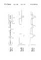
- FIG. 1 aillustrates a prior art transmission system having a transmitter, a long cable, and a receiver.
- FIG. 1 billustrates a proper DC signal with no drooping.
- FIG. 1 cillustrates a drooped DC signal.
- FIG. 2illustrates a circuit for restoring a drooped DC signal asynchronously.
- FIG. 3illustrates a circuit for restoring a drooped DC signal synchronously.
- FIG. 4 aillustrates the HYP signal which is the positive portion of the equalized signal.
- FIG. 4 billustrates the HYN signal which is the inverted negative portion of the equalized signal.
- FIG. 4 cillustrates a NRZI signal, which is the combined positive and inverted negative portions of the equalized signal.
- FIG. 5illustrates a circuit combining both the synchronous and asynchronous circuits for the restoration of a drooped signal.
- the transformer 32isolates the DC component of the received signal, and the received signal is DC shifted to match the required DC level of the equalizer 34 .
- the equalizercompensates the received signal according to the amount of attenuation.
- the equalized signalwhich is also the output signal for this circuit, is provided to two peak detectors, 36 and 38 .
- One peak detect 36continuously detects the positive peak of the equalized signal and the other peak detector 38 detects the peak of the signal inverted. The difference between the two peaks are then generated by a subtrator 40 and fed back to the equalizer 34 via a low pass filter 42 .
- the low pass filterreduces noise and is an optional block here.
- the difference between the two peakstranslates into a difference signal.
- the equalizercan add it to the just received signal path and thus correct drooping.
- the resulting output from the equalizer 34thus are better corrected for drooping.
- FIG. 3in synchronous mode, the drooped signal again is level shifted after a transformer 52 and equalized 54 .
- a slicer 56separates out the positive portion of the equalized signal (HYP signal) and the negative portion of the equalized signal (HPN signal).
- FIGS. 4 a and 4 billustrate examples of the HYP and HYN signals.
- the sliceralso generates a NRZI signal which is the sum of the HYP and HYN signals.
- FIG. 4 cillustrates the NRZI signal.
- the NRZI signalis provided to the clock recovery circuit 58 .
- the clock recovery circuitadjusts the NRZI signal for phase shift and attempts to lock the signal. Since the clock signal is of a known pattern, the NRZI signal is adjusted accordingly and provided as the output for this circuit.
- the clock recovery circuitalso provides a data lock signal to indicate whether the clock/data is locked or not.
- the HYP and HYN signalsare provided to a regeneration circuit. Since the expected voltage levels of the drooped signal is predefined, the band gap reference circuit 62 provides the expected and predefined Vhigh and Vlow signals to the regeneration circuit 60 . The regeneration circuit 60 receiving the HYN and HYP signals and the Vhigh and Vlow signals, generates a copy of the equalized signal except it is without drooping. The regenerated signal is compared against the equalized signal via a subtractor 64 . The subtractor 64 generates a difference signal and this signal is again low pass filtered and passed to the equalizer 54 . The equalizer 54 adds the difference signal to its signal path and outputs an equalized signal corrected for drooping.
- the two circuits illustrated in FIGS. 2 and 3are combined into a single circuit to generate the best result.
- the combined circuitoperates in two stages. Typically during the first stage, adaptation is not complete and the data after the slicer is not correct or useful.
- the data lock signal (DLOCK) from the clock recovery circuit 82indicates that the clock/data is not locked and drooping should be corrected by asynchronous mode.
- the DLOCK signalcauses the multiplexer 90 to select the output from the asynchronous portion of the circuit (from substrator 78 ).
- the clock recovery circuit 82asserts the DLOCK signal to cause the multiplexer 90 to select the output from subtractor 88 , which is the output from the synchronous portion of this circuit, resulting in a better corrected DC signal.
Landscapes
- Engineering & Computer Science (AREA)
- Physics & Mathematics (AREA)
- Nonlinear Science (AREA)
- Power Engineering (AREA)
- Computer Networks & Wireless Communication (AREA)
- Signal Processing (AREA)
- Dc Digital Transmission (AREA)
Abstract
Description
Claims (3)
Priority Applications (1)
| Application Number | Priority Date | Filing Date | Title |
|---|---|---|---|
| US09/415,680US6242961B1 (en) | 1998-10-08 | 1999-10-08 | Methods and circuits for restoration of a drooped DC signal |
Applications Claiming Priority (2)
| Application Number | Priority Date | Filing Date | Title |
|---|---|---|---|
| US10368798P | 1998-10-08 | 1998-10-08 | |
| US09/415,680US6242961B1 (en) | 1998-10-08 | 1999-10-08 | Methods and circuits for restoration of a drooped DC signal |
Publications (1)
| Publication Number | Publication Date |
|---|---|
| US6242961B1true US6242961B1 (en) | 2001-06-05 |
Family
ID=26800745
Family Applications (1)
| Application Number | Title | Priority Date | Filing Date |
|---|---|---|---|
| US09/415,680Expired - LifetimeUS6242961B1 (en) | 1998-10-08 | 1999-10-08 | Methods and circuits for restoration of a drooped DC signal |
Country Status (1)
| Country | Link |
|---|---|
| US (1) | US6242961B1 (en) |
Cited By (21)
| Publication number | Priority date | Publication date | Assignee | Title |
|---|---|---|---|---|
| US6586971B1 (en)* | 2001-12-18 | 2003-07-01 | Hewlett-Packard Development Company, L.P. | Adapting VLSI clocking to short term voltage transients |
| US20040190646A1 (en)* | 2003-03-24 | 2004-09-30 | Aziz Pervez M. | Processing servo data having DC level shifts |
| US20060045176A1 (en)* | 2004-08-27 | 2006-03-02 | Raed Moughabghab | System and method for digital adaptive equalization with failure detection and recovery |
| KR100624002B1 (en) | 2004-05-20 | 2006-09-19 | 주식회사 키스컴 | Pulse detector with DC component high-low split point tracking |
| KR100770334B1 (en) | 2006-09-08 | 2007-10-25 | 한국전기연구원 | Real time square wave-average value conversion circuit |
| US20080260016A1 (en)* | 2004-01-26 | 2008-10-23 | Diablo Technologies Inc. | Fully Adaptive Equalization for High Loss Communications Channels |
| US7583190B2 (en) | 2005-10-31 | 2009-09-01 | Abbott Diabetes Care Inc. | Method and apparatus for providing data communication in data monitoring and management systems |
| US7620437B2 (en) | 2005-06-03 | 2009-11-17 | Abbott Diabetes Care Inc. | Method and apparatus for providing rechargeable power in data monitoring and management systems |
| US7679407B2 (en)* | 2003-04-28 | 2010-03-16 | Abbott Diabetes Care Inc. | Method and apparatus for providing peak detection circuitry for data communication systems |
| US7727181B2 (en) | 2002-10-09 | 2010-06-01 | Abbott Diabetes Care Inc. | Fluid delivery device with autocalibration |
| US20100137698A1 (en)* | 2003-06-12 | 2010-06-03 | Abbott Diabetes Care Inc. | Method and Apparatus for Providing Power Management in Data Communication Systems |
| US7756561B2 (en) | 2005-09-30 | 2010-07-13 | Abbott Diabetes Care Inc. | Method and apparatus for providing rechargeable power in data monitoring and management systems |
| US7768408B2 (en) | 2005-05-17 | 2010-08-03 | Abbott Diabetes Care Inc. | Method and system for providing data management in data monitoring system |
| US7922458B2 (en) | 2002-10-09 | 2011-04-12 | Abbott Diabetes Care Inc. | Variable volume, shape memory actuated insulin dispensing pump |
| US8029460B2 (en) | 2005-03-21 | 2011-10-04 | Abbott Diabetes Care Inc. | Method and system for providing integrated medication infusion and analyte monitoring system |
| US8047811B2 (en) | 2002-10-09 | 2011-11-01 | Abbott Diabetes Care Inc. | Variable volume, shape memory actuated insulin dispensing pump |
| US8344966B2 (en) | 2006-01-31 | 2013-01-01 | Abbott Diabetes Care Inc. | Method and system for providing a fault tolerant display unit in an electronic device |
| US8467972B2 (en) | 2009-04-28 | 2013-06-18 | Abbott Diabetes Care Inc. | Closed loop blood glucose control algorithm analysis |
| US8560082B2 (en) | 2009-01-30 | 2013-10-15 | Abbott Diabetes Care Inc. | Computerized determination of insulin pump therapy parameters using real time and retrospective data processing |
| US8579853B2 (en) | 2006-10-31 | 2013-11-12 | Abbott Diabetes Care Inc. | Infusion devices and methods |
| US8798934B2 (en) | 2009-07-23 | 2014-08-05 | Abbott Diabetes Care Inc. | Real time management of data relating to physiological control of glucose levels |
Citations (1)
| Publication number | Priority date | Publication date | Assignee | Title |
|---|---|---|---|---|
| US5122677A (en)* | 1990-09-04 | 1992-06-16 | Fujitsu Limited | Instantaneous breakless clock switching apparatus |
- 1999
- 1999-10-08USUS09/415,680patent/US6242961B1/ennot_activeExpired - Lifetime
Patent Citations (1)
| Publication number | Priority date | Publication date | Assignee | Title |
|---|---|---|---|---|
| US5122677A (en)* | 1990-09-04 | 1992-06-16 | Fujitsu Limited | Instantaneous breakless clock switching apparatus |
Cited By (59)
| Publication number | Priority date | Publication date | Assignee | Title |
|---|---|---|---|---|
| US6586971B1 (en)* | 2001-12-18 | 2003-07-01 | Hewlett-Packard Development Company, L.P. | Adapting VLSI clocking to short term voltage transients |
| US8029245B2 (en) | 2002-10-09 | 2011-10-04 | Abbott Diabetes Care Inc. | Variable volume, shape memory actuated insulin dispensing pump |
| US7922458B2 (en) | 2002-10-09 | 2011-04-12 | Abbott Diabetes Care Inc. | Variable volume, shape memory actuated insulin dispensing pump |
| US8029250B2 (en) | 2002-10-09 | 2011-10-04 | Abbott Diabetes Care Inc. | Variable volume, shape memory actuated insulin dispensing pump |
| US8343093B2 (en) | 2002-10-09 | 2013-01-01 | Abbott Diabetes Care Inc. | Fluid delivery device with autocalibration |
| US7753873B2 (en)* | 2002-10-09 | 2010-07-13 | Abbott Diabetes Care Inc. | Fluid delivery device with autocalibration |
| US7993108B2 (en) | 2002-10-09 | 2011-08-09 | Abbott Diabetes Care Inc. | Variable volume, shape memory actuated insulin dispensing pump |
| US7993109B2 (en) | 2002-10-09 | 2011-08-09 | Abbott Diabetes Care Inc. | Variable volume, shape memory actuated insulin dispensing pump |
| US7766864B2 (en)* | 2002-10-09 | 2010-08-03 | Abbott Diabetes Care Inc. | Fluid delivery device with autocalibration |
| US7753874B2 (en)* | 2002-10-09 | 2010-07-13 | Abbott Diabetes Care Inc. | Fluid delivery device with autocalibration |
| US8047811B2 (en) | 2002-10-09 | 2011-11-01 | Abbott Diabetes Care Inc. | Variable volume, shape memory actuated insulin dispensing pump |
| US8047812B2 (en) | 2002-10-09 | 2011-11-01 | Abbott Diabetes Care Inc. | Variable volume, shape memory actuated insulin dispensing pump |
| US7727181B2 (en) | 2002-10-09 | 2010-06-01 | Abbott Diabetes Care Inc. | Fluid delivery device with autocalibration |
| US7466766B2 (en) | 2003-03-24 | 2008-12-16 | Agere Systems Inc. | Processing servo data having DC level shifts |
| US20070172005A1 (en)* | 2003-03-24 | 2007-07-26 | Aziz Pervez M | Processing servo data having DC level shifts |
| US7231001B2 (en)* | 2003-03-24 | 2007-06-12 | Agere Systems Inc. | Processing servo data having DC level shifts |
| US20040190646A1 (en)* | 2003-03-24 | 2004-09-30 | Aziz Pervez M. | Processing servo data having DC level shifts |
| US7679407B2 (en)* | 2003-04-28 | 2010-03-16 | Abbott Diabetes Care Inc. | Method and apparatus for providing peak detection circuitry for data communication systems |
| US8512246B2 (en) | 2003-04-28 | 2013-08-20 | Abbott Diabetes Care Inc. | Method and apparatus for providing peak detection circuitry for data communication systems |
| US8071028B2 (en) | 2003-06-12 | 2011-12-06 | Abbott Diabetes Care Inc. | Method and apparatus for providing power management in data communication systems |
| US8273295B2 (en) | 2003-06-12 | 2012-09-25 | Abbott Diabetes Care Inc. | Apparatus for providing power management in data communication systems |
| US20100137698A1 (en)* | 2003-06-12 | 2010-06-03 | Abbott Diabetes Care Inc. | Method and Apparatus for Providing Power Management in Data Communication Systems |
| US8906307B2 (en) | 2003-06-12 | 2014-12-09 | Abbott Diabetes Care Inc. | Apparatus for providing power management in data communication systems |
| US9109926B2 (en) | 2003-06-12 | 2015-08-18 | Abbott Diabetes Care Inc. | Method and apparatus for providing power management in data communication systems |
| US7940839B2 (en)* | 2004-01-26 | 2011-05-10 | Diablo Technologies Inc. | Fully adaptive equalization for high loss communications channels |
| US20080260016A1 (en)* | 2004-01-26 | 2008-10-23 | Diablo Technologies Inc. | Fully Adaptive Equalization for High Loss Communications Channels |
| KR100624002B1 (en) | 2004-05-20 | 2006-09-19 | 주식회사 키스컴 | Pulse detector with DC component high-low split point tracking |
| US20060045176A1 (en)* | 2004-08-27 | 2006-03-02 | Raed Moughabghab | System and method for digital adaptive equalization with failure detection and recovery |
| US7400675B2 (en)* | 2004-08-27 | 2008-07-15 | Mindspeed Technologies, Inc. | System and method for digital adaptive equalization with failure detection and recovery |
| US8343092B2 (en) | 2005-03-21 | 2013-01-01 | Abbott Diabetes Care Inc. | Method and system for providing integrated medication infusion and analyte monitoring system |
| US8029460B2 (en) | 2005-03-21 | 2011-10-04 | Abbott Diabetes Care Inc. | Method and system for providing integrated medication infusion and analyte monitoring system |
| US8029459B2 (en) | 2005-03-21 | 2011-10-04 | Abbott Diabetes Care Inc. | Method and system for providing integrated medication infusion and analyte monitoring system |
| US8471714B2 (en) | 2005-05-17 | 2013-06-25 | Abbott Diabetes Care Inc. | Method and system for providing data management in data monitoring system |
| US9750440B2 (en) | 2005-05-17 | 2017-09-05 | Abbott Diabetes Care Inc. | Method and system for providing data management in data monitoring system |
| US10206611B2 (en) | 2005-05-17 | 2019-02-19 | Abbott Diabetes Care Inc. | Method and system for providing data management in data monitoring system |
| US7768408B2 (en) | 2005-05-17 | 2010-08-03 | Abbott Diabetes Care Inc. | Method and system for providing data management in data monitoring system |
| US8653977B2 (en) | 2005-05-17 | 2014-02-18 | Abbott Diabetes Care Inc. | Method and system for providing data management in data monitoring system |
| US7884729B2 (en) | 2005-05-17 | 2011-02-08 | Abbott Diabetes Care Inc. | Method and system for providing data management in data monitoring system |
| US9332944B2 (en) | 2005-05-17 | 2016-05-10 | Abbott Diabetes Care Inc. | Method and system for providing data management in data monitoring system |
| US8089363B2 (en) | 2005-05-17 | 2012-01-03 | Abbott Diabetes Care Inc. | Method and system for providing data management in data monitoring system |
| US7620437B2 (en) | 2005-06-03 | 2009-11-17 | Abbott Diabetes Care Inc. | Method and apparatus for providing rechargeable power in data monitoring and management systems |
| US8112138B2 (en) | 2005-06-03 | 2012-02-07 | Abbott Diabetes Care Inc. | Method and apparatus for providing rechargeable power in data monitoring and management systems |
| US7756561B2 (en) | 2005-09-30 | 2010-07-13 | Abbott Diabetes Care Inc. | Method and apparatus for providing rechargeable power in data monitoring and management systems |
| US7583190B2 (en) | 2005-10-31 | 2009-09-01 | Abbott Diabetes Care Inc. | Method and apparatus for providing data communication in data monitoring and management systems |
| US7948370B2 (en) | 2005-10-31 | 2011-05-24 | Abbott Diabetes Care Inc. | Method and apparatus for providing data communication in data monitoring and management systems |
| US8638220B2 (en) | 2005-10-31 | 2014-01-28 | Abbott Diabetes Care Inc. | Method and apparatus for providing data communication in data monitoring and management systems |
| US8344966B2 (en) | 2006-01-31 | 2013-01-01 | Abbott Diabetes Care Inc. | Method and system for providing a fault tolerant display unit in an electronic device |
| KR100770334B1 (en) | 2006-09-08 | 2007-10-25 | 한국전기연구원 | Real time square wave-average value conversion circuit |
| US9064107B2 (en) | 2006-10-31 | 2015-06-23 | Abbott Diabetes Care Inc. | Infusion devices and methods |
| US8579853B2 (en) | 2006-10-31 | 2013-11-12 | Abbott Diabetes Care Inc. | Infusion devices and methods |
| US10007759B2 (en) | 2006-10-31 | 2018-06-26 | Abbott Diabetes Care Inc. | Infusion devices and methods |
| US11043300B2 (en) | 2006-10-31 | 2021-06-22 | Abbott Diabetes Care Inc. | Infusion devices and methods |
| US11508476B2 (en) | 2006-10-31 | 2022-11-22 | Abbott Diabetes Care, Inc. | Infusion devices and methods |
| US11837358B2 (en) | 2006-10-31 | 2023-12-05 | Abbott Diabetes Care Inc. | Infusion devices and methods |
| US12073941B2 (en) | 2006-10-31 | 2024-08-27 | Abbott Diabetes Care Inc. | Infusion device and methods |
| US8560082B2 (en) | 2009-01-30 | 2013-10-15 | Abbott Diabetes Care Inc. | Computerized determination of insulin pump therapy parameters using real time and retrospective data processing |
| US8467972B2 (en) | 2009-04-28 | 2013-06-18 | Abbott Diabetes Care Inc. | Closed loop blood glucose control algorithm analysis |
| US8798934B2 (en) | 2009-07-23 | 2014-08-05 | Abbott Diabetes Care Inc. | Real time management of data relating to physiological control of glucose levels |
| US10872102B2 (en) | 2009-07-23 | 2020-12-22 | Abbott Diabetes Care Inc. | Real time management of data relating to physiological control of glucose levels |
Similar Documents
| Publication | Publication Date | Title |
|---|---|---|
| US6242961B1 (en) | Methods and circuits for restoration of a drooped DC signal | |
| US6496552B2 (en) | Timing circuit | |
| JPH03186019A (en) | Technology for the purpose of determining signal dispersion characteristics in communication system | |
| DE69622095T2 (en) | Method and device for data reproduction | |
| JPH11243428A (en) | Method and equalizing filter for equalizing digitally transmitted signals | |
| US4991034A (en) | DC restoration circuit for restoring and compensating a low frequency component lost in a digital signal | |
| US6850584B2 (en) | Clock regeneration circuit and optical signal receiver using the same | |
| JPH06505381A (en) | Data transmission system receiver with phase independent band control | |
| JPS58108832A (en) | Signal regenerating circuit | |
| JPH027544B2 (en) | ||
| US6337650B1 (en) | System and method for regenerating clock signal | |
| US7088976B2 (en) | Device for reconstructing data from a received data signal and corresponding transceiver | |
| JP3649718B2 (en) | Measuring device for measuring characteristics of data transmission system with high accuracy and clock recovery circuit used therefor | |
| JPH0588023B2 (en) | ||
| JP3396067B2 (en) | Data processing circuit | |
| JPH0793617B2 (en) | Phase locked loop | |
| US6359941B1 (en) | System and method for improved reference threshold setting in a burst mode digital data receiver | |
| EP0594246B1 (en) | Data processing circuit | |
| JPS62269444A (en) | Digital information transmission equipment | |
| JP2001237724A (en) | Method and device for radio-transmitting audio signal by digital system | |
| JP2812290B2 (en) | Sub signal multiplexing circuit | |
| JPH01183248A (en) | Receiver of fm multiple data broadcasting | |
| KR910001427B1 (en) | Circuit for detecting data in digital transmission system | |
| KR0141198B1 (en) | Data restoration device by automatic potential control | |
| JPH09106626A (en) | Data processing device |
Legal Events
| Date | Code | Title | Description |
|---|---|---|---|
| AS | Assignment | Owner name:ALTIMA CORPORATION, INC., CALIFORNIA Free format text:ASSIGNMENT OF ASSIGNORS INTEREST;ASSIGNORS:LIU, JAMES;FANG, WEN;WU, WEN-CHUNG (STEWART);REEL/FRAME:010792/0687;SIGNING DATES FROM 20000420 TO 20000423 | |
| STCF | Information on status: patent grant | Free format text:PATENTED CASE | |
| FEPP | Fee payment procedure | Free format text:PAYOR NUMBER ASSIGNED (ORIGINAL EVENT CODE: ASPN); ENTITY STATUS OF PATENT OWNER: LARGE ENTITY | |
| FEPP | Fee payment procedure | Free format text:PAT HOLDER NO LONGER CLAIMS SMALL ENTITY STATUS, ENTITY STATUS SET TO UNDISCOUNTED (ORIGINAL EVENT CODE: STOL); ENTITY STATUS OF PATENT OWNER: LARGE ENTITY | |
| REFU | Refund | Free format text:REFUND - SURCHARGE, PETITION TO ACCEPT PYMT AFTER EXP, UNINTENTIONAL (ORIGINAL EVENT CODE: R2551); ENTITY STATUS OF PATENT OWNER: LARGE ENTITY | |
| FPAY | Fee payment | Year of fee payment:4 | |
| AS | Assignment | Owner name:BROADCOM CORPORATION, CALIFORNIA Free format text:MERGER;ASSIGNOR:ALTIMA COMMUNICATIONS, INC.;REEL/FRAME:015571/0985 Effective date:20040526 | |
| FPAY | Fee payment | Year of fee payment:8 | |
| FPAY | Fee payment | Year of fee payment:12 | |
| AS | Assignment | Owner name:BANK OF AMERICA, N.A., AS COLLATERAL AGENT, NORTH CAROLINA Free format text:PATENT SECURITY AGREEMENT;ASSIGNOR:BROADCOM CORPORATION;REEL/FRAME:037806/0001 Effective date:20160201 Owner name:BANK OF AMERICA, N.A., AS COLLATERAL AGENT, NORTH Free format text:PATENT SECURITY AGREEMENT;ASSIGNOR:BROADCOM CORPORATION;REEL/FRAME:037806/0001 Effective date:20160201 | |
| AS | Assignment | Owner name:AVAGO TECHNOLOGIES GENERAL IP (SINGAPORE) PTE. LTD., SINGAPORE Free format text:ASSIGNMENT OF ASSIGNORS INTEREST;ASSIGNOR:BROADCOM CORPORATION;REEL/FRAME:041706/0001 Effective date:20170120 Owner name:AVAGO TECHNOLOGIES GENERAL IP (SINGAPORE) PTE. LTD Free format text:ASSIGNMENT OF ASSIGNORS INTEREST;ASSIGNOR:BROADCOM CORPORATION;REEL/FRAME:041706/0001 Effective date:20170120 | |
| AS | Assignment | Owner name:BROADCOM CORPORATION, CALIFORNIA Free format text:TERMINATION AND RELEASE OF SECURITY INTEREST IN PATENTS;ASSIGNOR:BANK OF AMERICA, N.A., AS COLLATERAL AGENT;REEL/FRAME:041712/0001 Effective date:20170119 | |
| AS | Assignment | Owner name:AVAGO TECHNOLOGIES INTERNATIONAL SALES PTE. LIMITE Free format text:ASSIGNMENT OF ASSIGNORS INTEREST;ASSIGNOR:AVAGO TECHNOLOGIES GENERAL IP (SINGAPORE) PTE. LTD.;REEL/FRAME:047022/0620 Effective date:20180509 | |
| AS | Assignment | Owner name:AVAGO TECHNOLOGIES INTERNATIONAL SALES PTE. LIMITE Free format text:CORRECTIVE ASSIGNMENT TO CORRECT THE NATURE OF CONVEYANCE AND EFFECTIVE DATE PREVIOUSLY RECORDED ON REEL 047022 FRAME 0620. ASSIGNOR(S) HEREBY CONFIRMS THE MERGER;ASSIGNOR:AVAGO TECHNOLOGIES GENERAL IP (SINGAPORE) PTE. LTD.;REEL/FRAME:047185/0643 Effective date:20180509 | |
| AS | Assignment | Owner name:AVAGO TECHNOLOGIES INTERNATIONAL SALES PTE. LIMITE Free format text:CORRECTIVE ASSIGNMENT TO CORRECT THE EFFECTIVE DATE PREVIOUSLY RECORDED ON REEL 047185 FRAME 0643. ASSIGNOR(S) HEREBY CONFIRMS THE MERGER;ASSIGNOR:AVAGO TECHNOLOGIES GENERAL IP (SINGAPORE) PTE. LTD.;REEL/FRAME:047476/0845 Effective date:20180905 | |
| AS | Assignment | Owner name:AVAGO TECHNOLOGIES INTERNATIONAL SALES PTE. LIMITE Free format text:CORRECTIVE ASSIGNMENT TO CORRECT THE EFFECTIVE DATE OF MERGER PREVIOUSLY RECORDED AT REEL: 047185 FRAME: 0643. ASSIGNOR(S) HEREBY CONFIRMS THE CORRECTIVE MERGER;ASSIGNOR:AVAGO TECHNOLOGIES GENERAL IP (SINGAPORE) PTE. LTD.;REEL/FRAME:047959/0296 Effective date:20180905 |