US6241729B1 - Method and instrumentation for posterior interbody fusion - Google Patents
Method and instrumentation for posterior interbody fusionDownload PDFInfo
- Publication number
- US6241729B1 US6241729B1US09/179,799US17979998AUS6241729B1US 6241729 B1US6241729 B1US 6241729B1US 17979998 AUS17979998 AUS 17979998AUS 6241729 B1US6241729 B1US 6241729B1
- Authority
- US
- United States
- Prior art keywords
- template
- shaft
- handle
- distractor
- depth
- Prior art date
- Legal status (The legal status is an assumption and is not a legal conclusion. Google has not performed a legal analysis and makes no representation as to the accuracy of the status listed.)
- Expired - Fee Related
Links
Images


Classifications
- A—HUMAN NECESSITIES
- A61—MEDICAL OR VETERINARY SCIENCE; HYGIENE
- A61B—DIAGNOSIS; SURGERY; IDENTIFICATION
- A61B17/00—Surgical instruments, devices or methods
- A61B17/16—Instruments for performing osteoclasis; Drills or chisels for bones; Trepans
- A61B17/17—Guides or aligning means for drills, mills, pins or wires
- A61B17/1739—Guides or aligning means for drills, mills, pins or wires specially adapted for particular parts of the body
- A61B17/1757—Guides or aligning means for drills, mills, pins or wires specially adapted for particular parts of the body for the spine
- A—HUMAN NECESSITIES
- A61—MEDICAL OR VETERINARY SCIENCE; HYGIENE
- A61B—DIAGNOSIS; SURGERY; IDENTIFICATION
- A61B17/00—Surgical instruments, devices or methods
- A61B17/02—Surgical instruments, devices or methods for holding wounds open, e.g. retractors; Tractors
- A61B17/025—Joint distractors
- A—HUMAN NECESSITIES
- A61—MEDICAL OR VETERINARY SCIENCE; HYGIENE
- A61F—FILTERS IMPLANTABLE INTO BLOOD VESSELS; PROSTHESES; DEVICES PROVIDING PATENCY TO, OR PREVENTING COLLAPSING OF, TUBULAR STRUCTURES OF THE BODY, e.g. STENTS; ORTHOPAEDIC, NURSING OR CONTRACEPTIVE DEVICES; FOMENTATION; TREATMENT OR PROTECTION OF EYES OR EARS; BANDAGES, DRESSINGS OR ABSORBENT PADS; FIRST-AID KITS
- A61F2/00—Filters implantable into blood vessels; Prostheses, i.e. artificial substitutes or replacements for parts of the body; Appliances for connecting them with the body; Devices providing patency to, or preventing collapsing of, tubular structures of the body, e.g. stents
- A61F2/02—Prostheses implantable into the body
- A61F2/30—Joints
- A61F2/46—Special tools for implanting artificial joints
- A61F2/4603—Special tools for implanting artificial joints for insertion or extraction of endoprosthetic joints or of accessories thereof
- A61F2/4611—Special tools for implanting artificial joints for insertion or extraction of endoprosthetic joints or of accessories thereof of spinal prostheses
- A—HUMAN NECESSITIES
- A61—MEDICAL OR VETERINARY SCIENCE; HYGIENE
- A61B—DIAGNOSIS; SURGERY; IDENTIFICATION
- A61B17/00—Surgical instruments, devices or methods
- A61B17/02—Surgical instruments, devices or methods for holding wounds open, e.g. retractors; Tractors
- A61B17/025—Joint distractors
- A61B2017/0256—Joint distractors for the spine
- A—HUMAN NECESSITIES
- A61—MEDICAL OR VETERINARY SCIENCE; HYGIENE
- A61B—DIAGNOSIS; SURGERY; IDENTIFICATION
- A61B90/00—Instruments, implements or accessories specially adapted for surgery or diagnosis and not covered by any of the groups A61B1/00 - A61B50/00, e.g. for luxation treatment or for protecting wound edges
- A61B90/06—Measuring instruments not otherwise provided for
- A61B2090/062—Measuring instruments not otherwise provided for penetration depth
- A—HUMAN NECESSITIES
- A61—MEDICAL OR VETERINARY SCIENCE; HYGIENE
- A61F—FILTERS IMPLANTABLE INTO BLOOD VESSELS; PROSTHESES; DEVICES PROVIDING PATENCY TO, OR PREVENTING COLLAPSING OF, TUBULAR STRUCTURES OF THE BODY, e.g. STENTS; ORTHOPAEDIC, NURSING OR CONTRACEPTIVE DEVICES; FOMENTATION; TREATMENT OR PROTECTION OF EYES OR EARS; BANDAGES, DRESSINGS OR ABSORBENT PADS; FIRST-AID KITS
- A61F2/00—Filters implantable into blood vessels; Prostheses, i.e. artificial substitutes or replacements for parts of the body; Appliances for connecting them with the body; Devices providing patency to, or preventing collapsing of, tubular structures of the body, e.g. stents
- A61F2/02—Prostheses implantable into the body
- A61F2/30—Joints
- A61F2/46—Special tools for implanting artificial joints
- A61F2/4603—Special tools for implanting artificial joints for insertion or extraction of endoprosthetic joints or of accessories thereof
- A61F2002/4625—Special tools for implanting artificial joints for insertion or extraction of endoprosthetic joints or of accessories thereof with relative movement between parts of the instrument during use
- A61F2002/4627—Special tools for implanting artificial joints for insertion or extraction of endoprosthetic joints or of accessories thereof with relative movement between parts of the instrument during use with linear motion along or rotating motion about the instrument axis or the implantation direction, e.g. telescopic, along a guiding rod, screwing inside the instrument
- A—HUMAN NECESSITIES
- A61—MEDICAL OR VETERINARY SCIENCE; HYGIENE
- A61F—FILTERS IMPLANTABLE INTO BLOOD VESSELS; PROSTHESES; DEVICES PROVIDING PATENCY TO, OR PREVENTING COLLAPSING OF, TUBULAR STRUCTURES OF THE BODY, e.g. STENTS; ORTHOPAEDIC, NURSING OR CONTRACEPTIVE DEVICES; FOMENTATION; TREATMENT OR PROTECTION OF EYES OR EARS; BANDAGES, DRESSINGS OR ABSORBENT PADS; FIRST-AID KITS
- A61F2/00—Filters implantable into blood vessels; Prostheses, i.e. artificial substitutes or replacements for parts of the body; Appliances for connecting them with the body; Devices providing patency to, or preventing collapsing of, tubular structures of the body, e.g. stents
- A61F2/02—Prostheses implantable into the body
- A61F2/30—Joints
- A61F2/46—Special tools for implanting artificial joints
- A61F2002/4687—Mechanical guides for implantation instruments
Definitions
- the present inventionrelates generally to surgical procedures for spinal stabilization and more specifically to instrumentation and techniques for inserting a spinal implant within the intervertebral disc space between adjacent vertebra. More particularly, while aspects of the present invention may have other applications, the invention provides instruments and techniques especially suited for interbody fusion from a generally posterior approach to the spine.
- the drill guidewas thereafter removed following the reaming process to allow for the passage of the bone dowel which had an outer diameter significantly larger than the reamed bore and the inner diameter of the drill guide.
- the removal of the drill guideleft the dowel insertion phase completely unprotected.
- U.S. Pat. No. 5,484,437 to Michelsondiscloses a technique and associated instrumentation for inserting a fusion device from a posterior surgical approach that provides greater protection for the surrounding tissues and neurological structures during the procedure.
- the surgical techniqueinvolves the use of a distractor having a penetrating portion that urges the vertebral bodies apart to facilitate the introduction of the necessary surgical instrumentation.
- the '437 patentalso discloses a hollow sleeve having teeth at one end that are driven into the vertebrae adjacent the disc space created by the distractor. These teeth engage the vertebra to maintain the disc space height during subsequent steps of the procedure following removal of the distractor.
- a drillis passed through the hollow sleeve to remove portions of the disc material and vertebral bone to produce a prepared bore for insertion of the fusion device.
- the drillis then removed from the sleeve and the fusion device is positioned within the disc space using an insertion tool.
- the present inventionis directed to this need and provides convenient methods and instruments to insure safe and effective preparation of a disc space in conjunction with implant placement.
- One object of the present inventionis to provide an improved retractor assembly permitting variable placement of the handle with respect to a retractor blade.
- the retractorcomprises a retractor blade, a shaft having a first portion connected to the retractor blade, and an opposite second portion pivotally connected to a handle.
- the assemblyfurther includes a locking mechanism selectively locking the handle to the second portion to limit pivotal movement of the handle in relation to the shaft.
- a method of dura retractionfor posterior access to the spine.
- the methodcomprises providing a retractor having a retractor blade pivotally connected to a handle, and the handle having a locking mechanism to selectively lock the handle to the retractor.
- a portion of the durais exposed and the retractor is inserted with the handle in an insertion position and the locking mechanism in a locked position.
- the durais then retracted to expose underlying spinal elements.
- the locking mechanismis unlocked to allow the handle to pivot in relation to the retractor blade.
- the handleis pivoted to a holding position and locked to maintain the handle in the locked position.
- a further aspect of the present inventionis a template for straddling the dura in a spinal surgery to facilitate marking a surgical site to gain access to the disc space in preparation for implant placement.
- the templatecomprises a body having an upper surface and a lower surface facing the dura, and an opening formed between the upper surface and the lower surface.
- a shafthaving a first end and a second end is connected to the body and extends away from the upper surface.
- a working tubeis connected to the body in substantial alignment with the opening and extends from the lower surface, the tube having a first diameter.
- a locator extensionengages the body and is spaced from the tube to provide a space for passage of the dura therebetween.
- the locator extensionextends from the lower surface and has a second diameter that is less than the tube diameter.
- the bodymay be formed to match the maximum area of the insertion instrumentation at the engagement with the vertebral bodies, thereby allowing marking of the bone needing removal.
- the distractorincludes a tapered shaft portion.
- a windowmay be formed through the shaft for visualization.
- the assemblycomprises a driving portion removably coupled to a distractor tip.
- the driving portionis coupled to transmit rotational and longitudinal forces.
- the assemblyincludes an outer shaft having a first driving shoulder for transmitting rotational force end and an opposite second driving shoulder for receiving a rotational force.
- An inner shaftis slidably disposed within at least a portion of the outer shaft, the inner shaft having a first connection end and an opposite second connection end. The first connection end is disposed adjacent the first driving shoulder.
- the assemblyfurther includes a distraction tip, the tip having a driving surface adapted for engagement with the first driving shoulder and a connection surface adapted for engagement with the first connection end.
- a handleinterconnects the inner and outer shafts and maintains the tip in contact with the outer shaft.
- the outer shaftis tapered to provide greater visualization. Further, the outer shaft may have a visualization window extending there through.
- the instrumentcomprises an elongated shaft and preferably a radiolucent tip attached to the shaft, the tip including at least on radiopaque marker.
- the instrumentincludes a distal tip sized to match the diameter or shape of the opening intending to be created.
- the present inventionalso contemplates a method of preparing a disc space and inserting an implant.
- the methodutilizes one or more of the instruments described above to prepare the disc space for receiving an implant.
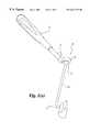
- FIG. 1 ( a )is a perspective view of a retractor according to the present invention.
- FIG. 1 ( b )is a partial cross-sectional side view of the retractor of FIG. 1 .
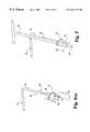
- FIG. 2 ( a )is an end view of a shaft of a portion of the retractor of FIG. 1 .
- FIG. 2 ( b )is a side view of the retractor shaft of FIG. 1 .
- FIG. 3 ( a )is a side view of the handle of FIG. 1 .
- FIG. 3 ( b )is a bottom view of the handle of FIG. 3 ( a ).
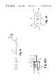
- FIG. 4 ( a )is a perspective view of an intraoperative template according to another aspect of the present invention.
- FIG. 4 ( b )is a partial cross-sectional side view of the intraoperative template of FIG. 4 ( a ).
- FIG. 5is a perspective view of a further embodiment of an intraoperative template according to the present invention.
- FIG. 6is a perspective view of still a further embodiment of an intraoperative template according to the present invention.
- FIG. 7is perspective view of the intraoperative template of FIG. 6 with handle and trephine.
- FIG. 8is a perspective view of yet a further embodiment of an intraoperative template according to the present invention.
- FIG. 9is a perspective view of still a further intraoperative template.
- FIG. 10is a cross-sectional view of the embodiment of FIG. 4 ( a ).
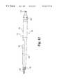
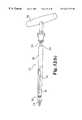
- FIG. 11is a perspective view of a distractor according to the present invention.
- FIG. 12 ( a )is an exploded perspective view of a modular distractor according to the present invention.
- FIG. 12 ( b )is a substantially assembled perspective view of the modular distractor of FIG. 12 ( a ).
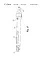
- FIG. 13is a plan elevation of a fully assembled distractor of FIG. 12 ( b ).
- FIGS. 14 ( a ) through 14 ( c )are partial cross-sectional side views taken along line 14 a - 14 a showing the modular distractor according to FIG. 13 .
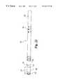
- FIG. 15is a side elevational view of an outer sleeve according to the present invention.
- FIG. 16is a side view of the outer sleeve of FIG. 15 rotated 90° about the longitudinal axis.
- FIG. 17is a perspective view of the outer sleeve of FIG. 15 in combination with the distractor of FIG. 13 .
- FIG. 18is a perspective view of a depth stop according to one aspect of the present invention.
- FIG. 19 ( a )is a side-elevational view of the depth stop of FIG. 22 .
- FIG. 19 ( b )is a side view of the depth stop of FIG. 19 ( a ) rotated 90° about its longitudinal axis.
- FIG. 19 ( c )is a cross-sectional view of the depth stop of FIG. 19 ( b ).
- FIG. 20is a side-elevational view of an alternative embodiment of a depth stop according to the present invention.
- FIG. 21is a perspective view of an outer sleeve in combination with a depth stop and reamer.
- FIG. 22is a perspective view of a depth gauge according to one aspect of the present invention.
- FIG. 23is a perspective view of the depth gauge of FIG. 22 in combination with an outer sleeve.
- FIG. 24is a perspective view of a tap in combination with an outer sleeve.
- FIG. 25is a perspective view of an implant inserter in accordance with another aspect of the present invention.
- the present inventionrelates generally to instruments and methods for performing vertebral interbody fusion. While it should be understood that the instruments disclosed herein may have many uses, it is particularly contemplated that they may be used to perform vertebral interbody fusion from a generally posterior approach to the spine. Such procedures typically involve the placement of dowels or other implants into the intervertebral disc space to promote fusion between adjacent vertebral bodies and to stabilization of the spine. Such implants may be formed of metal, ceramics, composites, bone or other bio-compatible materials, depending on the properties desired from the implant.
- Retractor 10includes a handle 12 pivotally connected to a shaft 14 having a distal end 17 connected to a retractor blade 16 . While retractor blade 16 is shown as a semi-circular blade, it is contemplated that any of a variety of retractor blade shapes may be utilized in conjunction with handle 12 and shaft 14 of the present invention.
- Handle 12is pivotable in relation to shaft 14 and may be releasably connected to shaft 14 adjacent enlarged end 18 . As shown more clearly in FIG. 2, enlarged end 18 includes a series of grooves 24 on its upper surface 36 .
- Handle 12includes a locking mechanism 22 adapted to selectively engage annular groove 26 extending around enlarged end 18 of shaft 14 , and at least one of grooves 24 disposed on the upper surface 36 .
- locking mechanism 22includes a flange 28 adapted for engaging a portion of annular groove 26 disposed on shaft 14 .
- flange 28extends in a semi-circular fashion and includes substantially parallel straight extensions 31 and 33 positioned adjacent opening 35 .
- Flange 28defines an opening 35 for receiving a portion of the enlarged head 18 of shaft 14 to hold the shaft and handle in mating engagement.
- Locking mechanism 22further includes an upper plate 34 having a downwardly extending internal projection 30 adapted to engage one of grooves 24 on shaft 14 . Although only a single projection 30 is shown, it will be understood that multiple projections may be provided to engage one or more grooves on shaft 14 .
- inner shaft 23Disposed within handle 12 is an inner shaft 23 slidable within outer shaft 32 to at least partially close opening 35 to prevent passage of enlarged end 18 from the channel formed by flange 28 .
- the position of inner shaft 23is controlled by movement of thumb lever 20 sliding within slot 21 formed in outer shaft 32 .
- Inner shaft 23includes a projection 29 adapted to engage a portion of annular groove 26 .
- inner shaft 23is biased to an extended position shown in FIG. 1 ( b ) by spring 38 captured within outer shaft 32 . In the extended position, inner shaft 23 retains handle 12 and shaft 14 in locked engagement.
- flange 28 of locking mechanism 22engages a semi-circular portion of annular groove 26 and projection 29 on inner shaft 23 also engages a further portion of annular groove 26 .
- This engagementmaintains handle 12 and shaft 14 securely engaged.
- grooves 24 on enlarged end 18are urged into engagement with projection 30 of locking mechanism 22 , thereby positioning the projection in one of the grooves 24 to prevent rotation of handle 12 about the longitudinal axis of shaft 14 .
- projection 29may be partially withdrawn from annular groove 26 by movement of thumb lever 20 in the direction of arrow 25 .
- shaft 14With projection 29 in the adjustment position, there may be sufficient transverse movement of shaft 14 within opening 35 to disengage projection 30 from grooves 24 thereby permitting pivotal movement of handle 12 in relation to shaft 14 without complete removal of the handle.
- inner shaft 23prevents movement of shaft 14 entirely out of opening 35 , thus maintaining the connection between handle 12 and shaft 14 .
- the handleWith the locking mechanism in the adjustment position, the handle may be pivotally repositioned to a variety of positions. It will be understood that in a preferred embodiment, shaft 14 includes eight grooves 24 , thereby permitting handle 12 to be locked in eight separate pivotal positions about shaft 14 . Although eight grooves 24 are shown, it is contemplated that more or less grooves may be provided to accommodate various positions.
- groovesare shown on the top of shaft 14 , it is contemplated that these may be placed around the exterior of enlarged head 18 to engage a projection correspondingly disposed in locking mechanism 22 . Further, the placement of grooves and projections may be reversed such that the shaft includes one or more projections mating with grooves in the locking mechanism. Other mechanisms known to those skilled in the art for allowing selective pivotal movement between the shaft and handle are contemplated and come within the scope of the present invention.
- a surgeonmay position the retractor device 10 to most effectively retract a desired neural structure or vessel.
- handle locking mechanism 22may be moved to the adjustment position and handle 12 pivoted about shaft 14 to a position for an assistant to maintain the tissue or vessel in the retracted position.
- the assistantwill be located on the opposite side of the patient from the surgeon and it is desirable that the handle be rotated out of the surgical field to provide the best access and visualization of the surgical site for the surgeon.
- the locking mechanismmay be returned to the locked position to securely hold the handle and shaft in the selected arrangement.
- handle 12may be removed from shaft 14 and utilized with a variety of instruments, such as those disclosed further herein.
- Use of a removable handle having the advantages described abovemay limit the total number of handles required for a surgical procedure or that must be supplied with a surgical set.
- Template 40includes a shaft 42 interconnected with handle 44 .
- Shaft 42is centrally connected to the upper side of template body 48 .
- Template body 48defines a number of bone marking notches 50 around its perimeter and includes an integrally formed guide tube 46 extending from its lower surface.
- an integrally formed guide tubeis shown in a preferred embodiment, it will be understood that a removable guide tube may be connected adjacent an aperture in the body.
- Guide tube 46defines a channel 47 to receive an instrument.
- Body 50further defines an opening 49 adapted to receive a locator extension 51 .
- FIG. 4 ( b )there is shown a partial cross-sectional view of the template of FIG. 4 ( a ).
- a removable locator extension 51having a head 53 .
- locator extension 51may be threadably received with opening 49 to prevent dislodgment.
- Diameter 41 of guide tube 46is substantially larger than diameter 43 of locator extension 51 .
- guide tube 46 and locator extension 51are in substantially parallel alignment.
- a second template 52includes a handle 54 connected to a shaft 56 which is centrally connected to template body 58 .
- Template body 58further includes guide tube 60 and integrally formed post 62 .
- a trephine 64is illustrated extending into and through guide tube 60 with trephine cutting head 66 extending beyond distal end 61 of guide tube 60 .
- the addition of post 62 to the templatepermits a surgeon to straddle the dura and place post 62 to further assist in the alignment of any further trephining procedures.
- template body 48includes six indentations 50 along the perimeter of the device.
- the perimeter of the devicematches the amount of exposure required for placement of a pair of implants.
- the bodyis sized to match the space needed to place two cylindrical bone dowels. Therefore, if in placing template body 48 , bony structures are encountered which extend into the area needed for implant placement, notches 68 , 70 , 72 , and similar notches on the other portion of the template permit marking of the interfering structure and ultimately passage of a working channel for placement of interbody fusion devices.
- FIGS. 6 and 7illustrate still a further embodiment of an intraoperative template according to the present invention.
- Intraoperative template 80includes a shaft 82 and an enlarged end 84 similar to the enlarged end 18 previously described on shaft 14 of the retractor mechanism disclosed in FIG. 1 .
- handle 98is identical to handle 12 and may be pivotally positioned on shaft 82 .
- Intraoperative template 80includes a template body 86 , a guiding tube 88 , and an aperture 94 extending through template body 86 .
- a removable post 92 with attached handle 90has been placed in opening 94 to drop into a first trephine hole or to penetrate the disc annulus to stabilize the template during trephining of a first hole through guide tube 88 . It will be understood that post 92 and handle 90 may be removed for unilateral templating if desired.
- FIG. 7there is shown the intraoperative template of FIG. 6 with interconnected handle 98 joined by connection mechanism 100 as previously described with respect to the retractor mechanism of FIG. 1.
- a trephine 96is further disclosed extending through guide tube 88 .
- Template 116has a template body and guide tube as previously described with respect to FIG. 6 .
- shaft 117includes an offset portion 118 laterally offsetting enlarged head 119 from the lower portion of the shaft. It will be understood that this limits the amount of instrumentation within the surgical field and permits greater access.
- Intraoperative template 101includes a connection mechanism 104 on shaft 102 , a template body 106 , guiding tube 108 , and a post 110 .
- post 110includes a substantially straight portion 112 in substantial alignment with the connection 113 of post 110 to template body 106 . Between straight section 112 and connection 113 , is a laterally extending curved portion 114 . It will be understood that the curvature of rod 112 away from tube 108 provides still further space for disposing the dura 116 between tube 108 and post 110 during the templating procedure.
- Post 110may be removably secured to body 106 .
- post 110is illustrated having a particular curve, it being understood that the locator extension may take an alternative configuration and remain within the scope of the present invention.
- Distractor 130includes a shaft 131 with a Hudson-type connection 132 and markings 134 indicating the distraction height created in the disc space by the distraction tip 136 .
- Disposed adjacent indicators 134is a substantially uniform diameter guiding portion 144 .
- Extending further towards distraction tip 136is a continuously tapering portion 142 .
- Disposed adjacent distractor tip 136is a further set of indicators 138 , again indicating the height of distraction in the disc space created by the orientation of tip 136 .
- Disposed within tapering section 142is a visualization window 140 extending entirely through shaft 131 permitting visualization of structures and vessels on the opposite side of the shaft.
- the distractor tip of FIG. 11is a two-position distractor having an insertion position with a first working distraction height. If the first working distraction height is insufficient or a greater distraction is desired, the shaft may be rotated 90° to a second greater working distraction height.
- the modular distraction assembly 150permits interchangeability of distraction tips, as well as the ability to leave the distraction tip disposed within the disc space while removing the insertion tool.
- the modular distraction assembly 150includes a T-handle 180 with a conventional Hudson-type connection mechanism 181 disposed therein.
- the assemblyfurther includes an inner shaft 152 having an enlarged end 154 adapted for engagement with Hudson mechanism 181 and an opposite threaded end 156 .
- Inner shaft 152may be disposed within outer tube 160 .
- Outer tube 160includes a slot driver 162 and an opposite end driving extension 164 having flats 166 for engagement with the T-handle 180 to transmit rotational force to outer tube 160 .
- outer tubeincludes a visualization window 168 extending therethrough.
- Distractor tip 176has an internal channel 179 defining internal threads 177 for engagement with threaded end 156 of inner shaft 152 and a slot 178 for engagement with the slot driver of outer tube 160 (see FIG. 14 ( c )).
- FIGS. 14 ( a ) through ( c )there is shown a cross-section of the assembled modular distraction assembly 150 .
- enlarged end 155 of inner shaft 152is advanced past balls 186 such that the balls are adjacent a smaller outer diameter 157 of the inner shaft 152 .
- Collar 184is then advanced towards outer tube 160 such that inclined surfaces 188 extend below balls 186 and reduced internal diameter portion 190 is disposed adjacent balls 186 to forcibly urge balls 186 against reduced outer diameter 157 of shaft 152 .
- Handle 180includes a shaft portion 181 having a configuration adapted to engage the driving flats of extension 164 .
- inner shaft 152must be threadedly engaged with distraction tip 176 prior to attachment of T-handle such that the distal end 171 of outer tube 160 engages the enlarged head 173 of distraction tip 176 to secure the outer tube 160 in engagement with handle 180 .
- collar 184must be pulled toward handle 180 until balls 186 are adjacent inclined surfaces 188 and allowed to move away from inner shaft 152 . In this position, handle 180 may be displaced longitudinally away from outer tube 160 and removed.
- inner shaft 152may be rotated to threadedly disengage from distractor tip 176 , thereby allowing the inner shaft and outer tube 160 to be disengaged from distractor tip 176 .
- Inner shaft 152is preferably retained within outer tube 160 by threads 161 .
- Threads 161are larger than the internal diameter of threaded opening 163 . For complete removal, threads 161 may be threadedly passed through threaded opening 163 .
- Outer sleeve 210includes a distractor portion 212 having a tip 216 and tapering portion 214 extending back to an area of grooves 218 adapted to engage adjacent bony structures.
- An opposing distractor portion 213is similarly formed.
- the bone engaging portionfurther includes spikes 220 and 221 adapted to be driven into bony structures adjacent the disc space.
- Outer sleeve 210further includes visualization windows 222 and 224 .
- Window 222extends to extended side wall 226 .
- window 224extends closer to the engagement end and terminates adjacent side wall 228 .
- side wall 226is substantially longer than side wall 228 along longitudinal axis 211 . As shown in FIG. 15, the longer portion of side wall 226 is provided to engage and protect nerve roots exiting the spinal cord adjacent the surgical site. In contrast, shortened wall 28 provides greater visualization through window 224 . Additionally, outer tube 210 includes a markings visualization window 232 for visualizing markings on instruments in the tube indicating the depth of instrument penetration into the disc space.
- FIG. 17there is shown a combination of the distractor assembly 150 having a distractor tip 176 in combination with outer sleeve 210 .
- Window 224permits visualization of the distractor assembly while window 232 permits visualization of markings along the distractor assembly shaft indicating the depth of penetration of the distractor and/or outer sleeve. It will be understood that in a typical procedure, distraction assembly 150 is placed prior to the insertion and placement of outer sleeve 210 .
- Depth stop 300includes an enlarged circumferential abutment shoulder 310 adapted to engage the proximal end of an outer working sleeve to prevent further advancement of the stop and any interconnected shaft. Stop 300 further includes viewing windows 308 to permit visualization of depth markings on a shaft extending within the stop. Stop 300 includes a manually operated collar 302 which may be axially displaced along axis 301 in the direction of arrow 305 to allow flexing of fingers 306 .
- Collar 302is normally urged into an extended position by spring 316 .
- fingers 306include projections 304 extending internally.
- the internal projections 304are configured for engagement within grooves defined along a tool shaft of a working tool.
- each fingerincludes an external taper portion 312 adapted for engagement with bearing surface 314 of collar 302 . It will be understood that with collar 302 in a retracted position, bearing surface 314 of collar 302 will be substantially disengaged from taper 312 and thereby permits fingers 306 to disengage from the groove of a tool shaft.
- bearing surfaces 314bear against the tapered surface 312 of each finger to urge projections 304 into a groove of a tool shaft.
- a usermay quickly and easily disengage the locking mechanism of the stop to advance or retract a tool shaft and then reengage the stop at the desired position.
- engagement with the tool shaftis indexed by the spacing of grooves on the shaft so the exact location of the stop may be easily known.
- the tool shaftmay be rotated with respect to the stop mechanism to display the appropriate depth numeral indicated on the shaft in window 308 .
- collar 302will extend at least partially beyond fingers 306 to limit the possibility that surgical staff may snag protective apparel on exposed fingers 306 .
- collar 302is retained on housing 306 by retaining pin 322 extending into the housing and through a slot 320 . Retaining pin 322 prevents rotation of collar 232 with respect to housing 318 .
- collar 302defines an L-shaped slot 324 which permits axial displacement of collar 302 with respect to body 318 , as well as a slight amount of rotation within the slot. It will be understood that the L-shaped slot 324 permits the depth stop mechanism to be locked in a disengaged position which permits free movement of a tool shaft through the depth stop. This is a desirable construction in some instances for easy removal of the depth stop from the tool shaft, as well as for utilization of the tool without the constraints of a depth stop mechanism.
- FIG. 21there is shown an outer sleeve 210 in combination with a depth stop 300 and reamer 351 .
- the reamer 351is interconnected with a T-handle 180 having Hudson connection engaged with the reamer shaft. It will be understood that depth stop 300 has been positioned to engage the upper portion of outer sleeve 210 to prevent further advancement of the reamer beyond the set depth.
- Depth gauge 360includes an upper portion 362 having a plurality of markings 366 indicating the depth of the distal portion of the gauge into the vertebral bodies.
- Lower portion 364is sized to substantially match the outer diameter of a cylindrical dowel to be inserted into an opening formed between adjacent vertebra. It will be understood that close matching of the outer diameter of depth gauge 360 with the desired diameter of the dowel to be placed, will insure that the opening formed between the vertebral bodies in the disc space is substantially clear of debris and closely matches the outer diameter of the dowel to be placed.
- portion 364is radiolucent and includes a number of markers to identify the location of the depth gauge by radiographic means. Radiomarker 372 indicates the most distal position of the depth gauge and subsequent position of the implant.
- Radiographic markings 370 and 376indicate the proximal ends of various sizes of implants.
- the distance 378 between 372 and 370is approximately 20 mm, a conventional implant size, while the distance between 372 and line 376 is approximately 26 mm, a further conventional implant length.
- FIG. 23there is shown the depth gauge of FIG. 22 inserted into and extending beyond outer sleeve 210 .
- the depth of extension beyond outer sleeve 210 of depth gauge 360is shown by the numeral in window 232 in the outer sleeve.
- FIG. 24illustrates a tap 390 interconnected with the shaft and handle 180 extending through outer sleeve 210 . It will be understood that markings on the shaft of the tap may be displayed in window 232 to indicate the length of extension beyond the outer tube. Additionally, the assembly includes an adjustable depth stop 300 which engages the proximal portion of outer sleeve 210 to prevent over-advancement of tap head 390 into the disc space.
- the implant insertion device 400includes depth markings along the shaft of the device. Depth markings 406 indicate when the dowel is first engaged in the disc space. In the past, it was possible that when one relied only upon feel, the dowel could engage obstructions within the working channel of the outer sleeve or other type of inserting device, giving the false impression that the implant 402 was engaging the disc space and potentially leading to damage to the implant as it was forced against the obstruction. With the markings 406 , multiple markings for different implant lengths, the user can visually verify whether the implant has engaged the disc space. Markings 404 are provided to indicate the depth the implant has been inserted into the disc space.
- an initial incisionprovides the approach and exposure of the posterior spinal surgical site. Exposure of the dura is accomplished in a customary fashion.
- a retractor according to the present inventionis used to retract the dura. Once retracted, the pivotal handle of the retractor is pivoted out of the way to permit an assistant to hold the retractor without interfering in the operating field.
- a template in accordance with the present inventionmay then be placed to extend on both sides of the dura simultaneously with a guide tube positioned on one side and a locator extension positioned on the opposite side.
- a trephineis then passed through the guide tube and into the disc space to remove a portion of the disc and adjacent tissue.
- the templatemay be removed and repositioned to again straddle the dura with the locator extension in the previously trephined hole and the guide positioned on the opposite side of the dura.
- the trephineis passed through the guide tube and into the disc space to form an opening therein. With the template remaining in position across the dura, the surrounding bone structures are evaluated for removal to permit placement of a guide sleeve.
- a marking devicesuch as a cautherizer is used to mark the offending structure in one of the notches provided.
- the templateis removed and the bone removed in a conventional manner.
- the templateis repositioned to straddle the dura and the field is again checked to verify that a guide tube may be placed without obstruction. If not, further bone marking and removal is conducted. Once the space is prepared for guide tube placement, the template is removed.
- a distractoris inserted into the disc space in one of the previously trephine openings.
- a second distractoris inserted into the second trephined opening.
- a distractor having two working heightsis inserted in a first smaller height and rotated 90 degrees after insertion to a second larger height.
- a tip having the desired configurationmay be selected and mounted on the modular distraction assembly 150 prior to insertion. In some instances, the tip may be disconnected from the distractor assembly and temporarily left in the disc space.
- a guide tubeis positioned over the distractor and advanced until the distracting flanges are positioned in the disc space. It will be understood that the enlarged portion on the distractor shaft guides the guide tube into a concentric position about the distractor. Once the guide tube is securely seated, the distractor may be withdrawn. The disc space will then be prepared to receive an implant having a preselected length and diameter. A reamer of the appropriate diameter is selected and a depth stop according to the present invention is positioned on the shaft at the preselected depth markings.
- the reameris rotatably advanced into the disc space until the depth stop engages the guide tube to limit further advancement.
- a depth gaugeaccording to the present invention is inserted to verify complete reaming to the preselected depth and removal of debris. If a threaded implant will be used, a depth stop will be positioned on a tap shaft at the preselected depth. The tap is rotatably inserted into the disc space until the depth stop engages the guide tube. The tap is removed and the depth gauge may be reinserted to verify that the proper sized opening has been formed and is substantially unobstructed. At this point an implant is inserted using the implant inserter. Once the implant is inserted, the guide tube may be withdrawn and the procedure repeated on the opposite side.
Landscapes
- Health & Medical Sciences (AREA)
- Life Sciences & Earth Sciences (AREA)
- Orthopedic Medicine & Surgery (AREA)
- Biomedical Technology (AREA)
- Engineering & Computer Science (AREA)
- Surgery (AREA)
- Veterinary Medicine (AREA)
- Heart & Thoracic Surgery (AREA)
- Animal Behavior & Ethology (AREA)
- General Health & Medical Sciences (AREA)
- Public Health (AREA)
- Transplantation (AREA)
- Oral & Maxillofacial Surgery (AREA)
- Medical Informatics (AREA)
- Molecular Biology (AREA)
- Nuclear Medicine, Radiotherapy & Molecular Imaging (AREA)
- Dentistry (AREA)
- Physical Education & Sports Medicine (AREA)
- Neurology (AREA)
- Cardiology (AREA)
- Vascular Medicine (AREA)
- Prostheses (AREA)
- Surgical Instruments (AREA)
Abstract
Description
Claims (9)
Priority Applications (6)
| Application Number | Priority Date | Filing Date | Title |
|---|---|---|---|
| US09/179,799US6241729B1 (en) | 1998-04-09 | 1998-10-27 | Method and instrumentation for posterior interbody fusion |
| PCT/US1999/007805WO1999052446A2 (en) | 1998-04-09 | 1999-04-09 | Method and instrumentation for posterior interbody fusion |
| AU35518/99AAU3551899A (en) | 1998-04-09 | 1999-04-09 | Method and instrumentation for posterior interbody fusion |
| US09/829,655US6506151B2 (en) | 1998-04-09 | 2001-04-10 | Method and instrumentation for posterior interbody fusion |
| US10/268,841US7722618B2 (en) | 1998-04-09 | 2002-10-10 | Method and instrumentation for posterior interbody fusion |
| US12/798,632US8066710B2 (en) | 1998-04-09 | 2010-04-08 | Distractor for posterior interbody fusion |
Applications Claiming Priority (3)
| Application Number | Priority Date | Filing Date | Title |
|---|---|---|---|
| US8120698P | 1998-04-09 | 1998-04-09 | |
| US09/179,799US6241729B1 (en) | 1998-04-09 | 1998-10-27 | Method and instrumentation for posterior interbody fusion |
| US09/829,655US6506151B2 (en) | 1998-04-09 | 2001-04-10 | Method and instrumentation for posterior interbody fusion |
Related Child Applications (1)
| Application Number | Title | Priority Date | Filing Date |
|---|---|---|---|
| US09/829,655DivisionUS6506151B2 (en) | 1998-04-09 | 2001-04-10 | Method and instrumentation for posterior interbody fusion |
Publications (1)
| Publication Number | Publication Date |
|---|---|
| US6241729B1true US6241729B1 (en) | 2001-06-05 |
Family
ID=27373931
Family Applications (4)
| Application Number | Title | Priority Date | Filing Date |
|---|---|---|---|
| US09/179,799Expired - Fee RelatedUS6241729B1 (en) | 1998-04-09 | 1998-10-27 | Method and instrumentation for posterior interbody fusion |
| US09/829,655Expired - LifetimeUS6506151B2 (en) | 1998-04-09 | 2001-04-10 | Method and instrumentation for posterior interbody fusion |
| US10/268,841Expired - Fee RelatedUS7722618B2 (en) | 1998-04-09 | 2002-10-10 | Method and instrumentation for posterior interbody fusion |
| US12/798,632Expired - Fee RelatedUS8066710B2 (en) | 1998-04-09 | 2010-04-08 | Distractor for posterior interbody fusion |
Family Applications After (3)
| Application Number | Title | Priority Date | Filing Date |
|---|---|---|---|
| US09/829,655Expired - LifetimeUS6506151B2 (en) | 1998-04-09 | 2001-04-10 | Method and instrumentation for posterior interbody fusion |
| US10/268,841Expired - Fee RelatedUS7722618B2 (en) | 1998-04-09 | 2002-10-10 | Method and instrumentation for posterior interbody fusion |
| US12/798,632Expired - Fee RelatedUS8066710B2 (en) | 1998-04-09 | 2010-04-08 | Distractor for posterior interbody fusion |
Country Status (3)
| Country | Link |
|---|---|
| US (4) | US6241729B1 (en) |
| AU (1) | AU3551899A (en) |
| WO (1) | WO1999052446A2 (en) |
Cited By (77)
| Publication number | Priority date | Publication date | Assignee | Title |
|---|---|---|---|---|
| US6443987B1 (en) | 2000-09-15 | 2002-09-03 | Donald W. Bryan | Spinal vertebral implant |
| US6500206B1 (en)* | 2000-09-15 | 2002-12-31 | Donald W. Bryan | Instruments for inserting spinal vertebral implant |
| US20030083664A1 (en)* | 2001-10-31 | 2003-05-01 | Christopher Rogers | Vertebral endplate chisel |
| US6641582B1 (en)* | 2000-07-06 | 2003-11-04 | Sulzer Spine-Tech Inc. | Bone preparation instruments and methods |
| US20030233145A1 (en)* | 2002-03-11 | 2003-12-18 | Landry Michael E. | Instrumentation and procedure for implanting spinal implant devices |
| US20040024291A1 (en)* | 2002-08-01 | 2004-02-05 | Zinkel John L. | Method and apparatus for spinal surgery |
| US20040176764A1 (en)* | 2003-03-03 | 2004-09-09 | Centerpulse Spine-Tech, Inc. | Apparatus and method for spinal distraction using a flip-up portal |
| US20050015093A1 (en)* | 2003-07-16 | 2005-01-20 | Suh Sean S. | Plating system with compression drill guide |
| US20050027301A1 (en)* | 2003-08-01 | 2005-02-03 | Pascal Stihl | Drill guide assembly for a bone fixation device |
| US20050038444A1 (en)* | 2003-08-13 | 2005-02-17 | Binder Lawrence J. | Quick-release drill-guide assembly for bone-plate |
| US20050049623A1 (en)* | 2003-09-02 | 2005-03-03 | Moore Jeffrey D. | Devices and techniques for a minimally invasive disc space preparation and implant insertion |
| US20050085909A1 (en)* | 2003-10-15 | 2005-04-21 | Sdgi Holding, Inc. | Semi-constrained and mobile-bearing disc prosthesis |
| US20050113842A1 (en)* | 2002-05-06 | 2005-05-26 | Rudolf Bertagnoli | Instrumentation and methods for preparation of an intervertebral space |
| US20050288677A1 (en)* | 2005-10-03 | 2005-12-29 | Inventit, Llc | Spinal surgery distractor with an integrated retractor |
| US20060068362A1 (en)* | 2004-09-27 | 2006-03-30 | Ormco Corporation | Endodontic instrument with depth markers |
| US20060074432A1 (en)* | 2004-10-06 | 2006-04-06 | Depuy Spine, Inc. | Modular medical tool and connector |
| US20060084986A1 (en)* | 2004-09-30 | 2006-04-20 | Depuy Spine, Inc. | Instrument and method for the insertion and alignment of an intervertebral implant |
| US20060089649A1 (en)* | 2004-10-26 | 2006-04-27 | Ullrich Peter F Jr | Surgical instruments and method of using same |
| US20060149286A1 (en)* | 2002-05-16 | 2006-07-06 | Boston Scientific Scimed, Inc. | Bone anchor implantation device |
| US20060184248A1 (en)* | 2005-02-17 | 2006-08-17 | Edidin Avram A | Percutaneous spinal implants and methods |
| US20060202242A1 (en)* | 2005-03-09 | 2006-09-14 | Sony Corporation | Solid-state imaging device |
| US20070049935A1 (en)* | 2005-02-17 | 2007-03-01 | Edidin Avram A | Percutaneous spinal implants and methods |
| US20070233076A1 (en)* | 2006-03-31 | 2007-10-04 | Sdgi Holdings, Inc. | Methods and instruments for delivering interspinous process spacers |
| US20070282340A1 (en)* | 2005-02-17 | 2007-12-06 | Malandain Hugues F | Percutaneous spinal implants and methods |
| US20070299526A1 (en)* | 2005-02-17 | 2007-12-27 | Malandain Hugues F | Percutaneous spinal implants and methods |
| US20080027552A1 (en)* | 1997-01-02 | 2008-01-31 | Zucherman James F | Spine distraction implant and method |
| US20080027433A1 (en)* | 2005-02-17 | 2008-01-31 | Kohm Andrew C | Percutaneous spinal implants and methods |
| US20080039853A1 (en)* | 1997-01-02 | 2008-02-14 | Zucherman James F | Spine distraction implant and method |
| US20080046087A1 (en)* | 2004-09-23 | 2008-02-21 | Zucherman James F | Interspinous process implant including a binder and method of implantation |
| US20080051894A1 (en)* | 2005-02-17 | 2008-02-28 | Malandain Hugues F | Percutaneous spinal implants and methods |
| US20080071376A1 (en)* | 2005-02-17 | 2008-03-20 | Kohm Andrew C | Percutaneous spinal implants and methods |
| US20080077152A1 (en)* | 2006-09-26 | 2008-03-27 | K2M, Inc. | Cervical drill guide apparatus |
| US20080177298A1 (en)* | 2006-10-24 | 2008-07-24 | St. Francis Medical Technologies, Inc. | Tensioner Tool and Method for Implanting an Interspinous Process Implant Including a Binder |
| US7544208B1 (en) | 2004-05-03 | 2009-06-09 | Theken Spine, Llc | Adjustable corpectomy apparatus |
| US20090198241A1 (en)* | 2008-02-04 | 2009-08-06 | Phan Christopher U | Spine distraction tools and methods of use |
| US7918876B2 (en) | 2003-03-24 | 2011-04-05 | Theken Spine, Llc | Spinal implant adjustment device |
| US7955392B2 (en) | 2006-12-14 | 2011-06-07 | Warsaw Orthopedic, Inc. | Interspinous process devices and methods |
| US7993342B2 (en) | 2005-02-17 | 2011-08-09 | Kyphon Sarl | Percutaneous spinal implants and methods |
| US8029567B2 (en) | 2005-02-17 | 2011-10-04 | Kyphon Sarl | Percutaneous spinal implants and methods |
| US20110251597A1 (en)* | 2010-04-08 | 2011-10-13 | Warsaw Orthopedic, Inc. | Neural-monitoring enabled sleeves for surgical instruments |
| US8096994B2 (en) | 2005-02-17 | 2012-01-17 | Kyphon Sarl | Percutaneous spinal implants and methods |
| US8114131B2 (en) | 2008-11-05 | 2012-02-14 | Kyphon Sarl | Extension limiting devices and methods of use for the spine |
| CN102429718A (en)* | 2010-08-30 | 2012-05-02 | 思邦科技脊柱智慧集团股份公司 | Set of instruments for twisting an implant into an intervertebral disc space |
| US8357184B2 (en) | 2009-11-10 | 2013-01-22 | Nuvasive, Inc. | Method and apparatus for performing spinal surgery |
| US8480715B2 (en) | 2007-05-22 | 2013-07-09 | Zimmer Spine, Inc. | Spinal implant system and method |
| US8636655B1 (en) | 2010-01-19 | 2014-01-28 | Ronald Childs | Tissue retraction system and related methods |
| US8840617B2 (en) | 2010-02-26 | 2014-09-23 | Warsaw Orthopedic, Inc. | Interspinous process spacer diagnostic parallel balloon catheter and methods of use |
| US8900137B1 (en) | 2011-04-26 | 2014-12-02 | Nuvasive, Inc. | Cervical retractor |
| US8974381B1 (en) | 2011-04-26 | 2015-03-10 | Nuvasive, Inc. | Cervical retractor |
| US9113853B1 (en) | 2011-08-31 | 2015-08-25 | Nuvasive, Inc. | Systems and methods for performing spine surgery |
| US9277906B2 (en) | 2011-04-19 | 2016-03-08 | NSI-US, Inc. | Quick-release handle for retractor blades |
| US9307972B2 (en) | 2011-05-10 | 2016-04-12 | Nuvasive, Inc. | Method and apparatus for performing spinal fusion surgery |
| US9408646B2 (en) | 2003-09-03 | 2016-08-09 | DePuy Synthes Products, Inc. | Bone plate with captive clips |
| US9414870B2 (en) | 2003-09-03 | 2016-08-16 | DePuy Synthes Products, Inc. | Translatable carriage fixation system |
| US9675389B2 (en) | 2009-12-07 | 2017-06-13 | Samy Abdou | Devices and methods for minimally invasive spinal stabilization and instrumentation |
| US9795370B2 (en) | 2014-08-13 | 2017-10-24 | Nuvasive, Inc. | Minimally disruptive retractor and associated methods for spinal surgery |
| USD802127S1 (en)* | 2014-06-02 | 2017-11-07 | Simplicity, Llc | Nasal dilator |
| US10034776B1 (en)* | 2011-03-01 | 2018-07-31 | John W. McClellan | Peripheral vertebral body spacer implant and insertion tool |
| USD834188S1 (en)* | 2014-06-02 | 2018-11-20 | Simplicity, Llc | Nasal dilator |
| US10548740B1 (en) | 2016-10-25 | 2020-02-04 | Samy Abdou | Devices and methods for vertebral bone realignment |
| US10575961B1 (en) | 2011-09-23 | 2020-03-03 | Samy Abdou | Spinal fixation devices and methods of use |
| US10695105B2 (en) | 2012-08-28 | 2020-06-30 | Samy Abdou | Spinal fixation devices and methods of use |
| WO2020243156A1 (en)* | 2019-05-31 | 2020-12-03 | Nico Corporation | Adapter for a surgical access device |
| US10857003B1 (en) | 2015-10-14 | 2020-12-08 | Samy Abdou | Devices and methods for vertebral stabilization |
| US10918498B2 (en) | 2004-11-24 | 2021-02-16 | Samy Abdou | Devices and methods for inter-vertebral orthopedic device placement |
| US10973648B1 (en) | 2016-10-25 | 2021-04-13 | Samy Abdou | Devices and methods for vertebral bone realignment |
| US11006982B2 (en) | 2012-02-22 | 2021-05-18 | Samy Abdou | Spinous process fixation devices and methods of use |
| US11173040B2 (en) | 2012-10-22 | 2021-11-16 | Cogent Spine, LLC | Devices and methods for spinal stabilization and instrumentation |
| US11179248B2 (en) | 2018-10-02 | 2021-11-23 | Samy Abdou | Devices and methods for spinal implantation |
| US11224447B2 (en) | 2019-02-13 | 2022-01-18 | Spine Wave, Inc. | Drill tap dilator |
| US20220167999A1 (en) | 2018-12-13 | 2022-06-02 | Paragon 28, Inc. | Alignment instruments and methods for use in total ankle replacement |
| US11399949B2 (en) | 2018-12-13 | 2022-08-02 | Paragon 28, Inc. | Total ankle replacement trial and preparation systems, guides, instruments and related methods |
| US11464522B2 (en)* | 2018-12-13 | 2022-10-11 | Paragon 28, Inc. | Distractors having attachable paddles, impaction devices, and methods for use in total ankle replacement |
| US11793504B2 (en) | 2011-08-19 | 2023-10-24 | Nuvasive, Inc. | Surgical retractor system and methods of use |
| US12133804B2 (en) | 2018-12-13 | 2024-11-05 | Paragon 28, Inc. | Total ankle replacement surgical method |
| US12156664B2 (en) | 2018-12-13 | 2024-12-03 | Paragon 28, Inc. | Resection guides, sweeping reamers, and methods for use in total ankle replacement |
| US12239550B2 (en) | 2018-12-13 | 2025-03-04 | Paragon 28, Inc. | Joint replacement alignment guides, systems and methods of use and assembly |
Families Citing this family (139)
| Publication number | Priority date | Publication date | Assignee | Title |
|---|---|---|---|---|
| IL128261A0 (en) | 1999-01-27 | 1999-11-30 | Disc O Tech Medical Tech Ltd | Expandable element |
| US20020019387A1 (en)* | 1997-09-24 | 2002-02-14 | Smithkline Beecham Corporation | Vitronectin receptor antagonist |
| US7776046B2 (en) | 1998-04-09 | 2010-08-17 | Warsaw Orthopedic, Inc. | Method and instrumentation for vertebral interbody fusion |
| US6428541B1 (en)* | 1998-04-09 | 2002-08-06 | Sdgi Holdings, Inc. | Method and instrumentation for vertebral interbody fusion |
| US6241729B1 (en)* | 1998-04-09 | 2001-06-05 | Sdgi Holdings, Inc. | Method and instrumentation for posterior interbody fusion |
| EP1146816B1 (en) | 1998-12-23 | 2005-10-12 | Nuvasive Inc. | Nerve surveillance cannulae systems |
| US7621950B1 (en) | 1999-01-27 | 2009-11-24 | Kyphon Sarl | Expandable intervertebral spacer |
| US6159179A (en) | 1999-03-12 | 2000-12-12 | Simonson; Robert E. | Cannula and sizing and insertion method |
| US6287313B1 (en)* | 1999-11-23 | 2001-09-11 | Sdgi Holdings, Inc. | Screw delivery system and method |
| WO2001037728A1 (en) | 1999-11-24 | 2001-05-31 | Nuvasive, Inc. | Electromyography system |
| DE60104286T2 (en) | 2000-02-22 | 2005-07-28 | SDGI Holdings, Inc., Wilmington | CUTLERY FOR PREPARING THE INTERMEDIATE ROOM |
| AU2001280476B2 (en) | 2000-06-30 | 2005-11-24 | Stephen Ritland | Polyaxial connection device and method |
| US6692434B2 (en) | 2000-09-29 | 2004-02-17 | Stephen Ritland | Method and device for retractor for microsurgical intermuscular lumbar arthrodesis |
| US7166073B2 (en) | 2000-09-29 | 2007-01-23 | Stephen Ritland | Method and device for microsurgical intermuscular spinal surgery |
| WO2002060330A1 (en)* | 2001-01-29 | 2002-08-08 | Stephen Ritland | Retractor and method for spinal pedicle screw placement |
| US6929606B2 (en)* | 2001-01-29 | 2005-08-16 | Depuy Spine, Inc. | Retractor and method for spinal pedicle screw placement |
| EP1417000B1 (en) | 2001-07-11 | 2018-07-11 | Nuvasive, Inc. | System for determining nerve proximity during surgery |
| JP2005503857A (en) | 2001-09-25 | 2005-02-10 | ヌバシブ, インコーポレイテッド | Systems and methods for performing surgical procedures and surgical diagnosis |
| DE60238997D1 (en) | 2001-09-28 | 2011-03-03 | Stephen Ritland | CHROME OR HOOKS |
| US7824410B2 (en) | 2001-10-30 | 2010-11-02 | Depuy Spine, Inc. | Instruments and methods for minimally invasive spine surgery |
| US7008431B2 (en) | 2001-10-30 | 2006-03-07 | Depuy Spine, Inc. | Configured and sized cannula |
| US6916330B2 (en)* | 2001-10-30 | 2005-07-12 | Depuy Spine, Inc. | Non cannulated dilators |
| ATE476930T1 (en) | 2002-02-20 | 2010-08-15 | Stephen Ritland | DEVICE FOR CONNECTING HAND SCREWS |
| US20030187431A1 (en)* | 2002-03-29 | 2003-10-02 | Simonson Robert E. | Apparatus and method for targeting for surgical procedures |
| US6966910B2 (en) | 2002-04-05 | 2005-11-22 | Stephen Ritland | Dynamic fixation device and method of use |
| ATE552789T1 (en) | 2002-05-08 | 2012-04-15 | Stephen Ritland | DYNAMIC FIXATION DEVICE |
| US7153303B2 (en)* | 2002-06-19 | 2006-12-26 | Sdgi Holdings, Inc. | Guide and blade for contouring vertebral bodies |
| US7582058B1 (en) | 2002-06-26 | 2009-09-01 | Nuvasive, Inc. | Surgical access system and related methods |
| US7083625B2 (en) | 2002-06-28 | 2006-08-01 | Sdgi Holdings, Inc. | Instruments and techniques for spinal disc space preparation |
| CA2495404C (en)* | 2002-08-15 | 2011-05-03 | Justin K. Coppes | Intervertebral disc implant |
| EP1542626B1 (en) | 2002-08-15 | 2012-09-26 | Synthes GmbH | Controlled artificial intervertebral disc implant |
| US7172561B2 (en)* | 2002-09-20 | 2007-02-06 | Depuy Acromed | Spreader tensiometer for measuring tension in an intervertebral disc space |
| US7625378B2 (en)* | 2002-09-30 | 2009-12-01 | Warsaw Orthopedic, Inc. | Devices and methods for securing a bone plate to a bony segment |
| US8137284B2 (en) | 2002-10-08 | 2012-03-20 | Nuvasive, Inc. | Surgical access system and related methods |
| US6869398B2 (en)* | 2003-01-06 | 2005-03-22 | Theodore G. Obenchain | Four-blade surgical speculum |
| US7691057B2 (en) | 2003-01-16 | 2010-04-06 | Nuvasive, Inc. | Surgical access system and related methods |
| US7458977B2 (en)* | 2003-02-04 | 2008-12-02 | Zimmer Technology, Inc. | Surgical navigation instrument useful in marking anatomical structures |
| EP1596738A4 (en) | 2003-02-25 | 2010-01-20 | Stephen Ritland | Adjustable rod and connector device and method of use |
| US7819801B2 (en) | 2003-02-27 | 2010-10-26 | Nuvasive, Inc. | Surgical access system and related methods |
| US20050049590A1 (en)* | 2003-03-07 | 2005-03-03 | Neville Alleyne | Spinal implant with securement spikes |
| ES2545328T3 (en) | 2003-03-14 | 2015-09-10 | Depuy Spine, Inc. | Bone cement hydraulic injection device in percutaneous vertebroplasty |
| US8066713B2 (en) | 2003-03-31 | 2011-11-29 | Depuy Spine, Inc. | Remotely-activated vertebroplasty injection device |
| US20060200128A1 (en)* | 2003-04-04 | 2006-09-07 | Richard Mueller | Bone anchor |
| WO2004110247A2 (en) | 2003-05-22 | 2004-12-23 | Stephen Ritland | Intermuscular guide for retractor insertion and method of use |
| US8415407B2 (en) | 2004-03-21 | 2013-04-09 | Depuy Spine, Inc. | Methods, materials, and apparatus for treating bone and other tissue |
| US7811329B2 (en) | 2003-07-31 | 2010-10-12 | Globus Medical | Transforaminal prosthetic spinal disc replacement and methods thereof |
| US7621956B2 (en)* | 2003-07-31 | 2009-11-24 | Globus Medical, Inc. | Prosthetic spinal disc replacement |
| US7955355B2 (en) | 2003-09-24 | 2011-06-07 | Stryker Spine | Methods and devices for improving percutaneous access in minimally invasive surgeries |
| US8002798B2 (en) | 2003-09-24 | 2011-08-23 | Stryker Spine | System and method for spinal implant placement |
| US7905840B2 (en) | 2003-10-17 | 2011-03-15 | Nuvasive, Inc. | Surgical access system and related methods |
| JP4463819B2 (en) | 2003-09-25 | 2010-05-19 | ヌヴァシヴ インコーポレイテッド | Surgical access system |
| US8579908B2 (en) | 2003-09-26 | 2013-11-12 | DePuy Synthes Products, LLC. | Device for delivering viscous material |
| US7108698B2 (en)* | 2004-01-13 | 2006-09-19 | Zimmer Spine, Inc. | Combined distractor and retractor instrument and methods |
| US7163542B2 (en)* | 2004-03-30 | 2007-01-16 | Synthes (U.S.A.) | Adjustable depth drill bit |
| US7909843B2 (en) | 2004-06-30 | 2011-03-22 | Thompson Surgical Instruments, Inc. | Elongateable surgical port and dilator |
| CN101065080B (en) | 2004-07-30 | 2021-10-29 | 德普伊新特斯产品有限责任公司 | Materials and Instruments for Manipulating Bone and Other Tissues |
| US9662158B2 (en) | 2004-08-09 | 2017-05-30 | Si-Bone Inc. | Systems and methods for the fixation or fusion of bone at or near a sacroiliac joint |
| US8425570B2 (en) | 2004-08-09 | 2013-04-23 | Si-Bone Inc. | Apparatus, systems, and methods for achieving anterior lumbar interbody fusion |
| US8388667B2 (en) | 2004-08-09 | 2013-03-05 | Si-Bone, Inc. | Systems and methods for the fixation or fusion of bone using compressive implants |
| US8414648B2 (en) | 2004-08-09 | 2013-04-09 | Si-Bone Inc. | Apparatus, systems, and methods for achieving trans-iliac lumbar fusion |
| US9949843B2 (en) | 2004-08-09 | 2018-04-24 | Si-Bone Inc. | Apparatus, systems, and methods for the fixation or fusion of bone |
| US20060036251A1 (en) | 2004-08-09 | 2006-02-16 | Reiley Mark A | Systems and methods for the fixation or fusion of bone |
| US20180228621A1 (en) | 2004-08-09 | 2018-08-16 | Mark A. Reiley | Apparatus, systems, and methods for the fixation or fusion of bone |
| US20070156241A1 (en) | 2004-08-09 | 2007-07-05 | Reiley Mark A | Systems and methods for the fixation or fusion of bone |
| US8470004B2 (en) | 2004-08-09 | 2013-06-25 | Si-Bone Inc. | Apparatus, systems, and methods for stabilizing a spondylolisthesis |
| US7455639B2 (en) | 2004-09-20 | 2008-11-25 | Stephen Ritland | Opposing parallel bladed retractor and method of use |
| WO2006042241A2 (en) | 2004-10-08 | 2006-04-20 | Nuvasive, Inc. | Surgical access system and related methods |
| US7427264B2 (en)* | 2005-04-22 | 2008-09-23 | Warsaw Orthopedic, Inc. | Instruments and methods for selective tissue retraction through a retractor sleeve |
| US8177817B2 (en) | 2005-05-18 | 2012-05-15 | Stryker Spine | System and method for orthopedic implant configuration |
| JP4988735B2 (en) | 2005-07-19 | 2012-08-01 | リットランド、ステファン | Rod extension for elongating fusion structures |
| US9381024B2 (en) | 2005-07-31 | 2016-07-05 | DePuy Synthes Products, Inc. | Marked tools |
| US9918767B2 (en) | 2005-08-01 | 2018-03-20 | DePuy Synthes Products, Inc. | Temperature control system |
| US20070082319A1 (en)* | 2005-10-12 | 2007-04-12 | Hyt System, Llc | Jaw retention device and method providing the same |
| US8360629B2 (en) | 2005-11-22 | 2013-01-29 | Depuy Spine, Inc. | Mixing apparatus having central and planetary mixing elements |
| WO2007130699A2 (en)* | 2006-01-13 | 2007-11-15 | Clifford Tribus | Spine reduction and stabilization device |
| EP1981422B1 (en)* | 2006-02-06 | 2018-10-24 | Stryker European Holdings I, LLC | Rod contouring apparatus for percutaneous pedicle screw extension |
| US8771282B2 (en)* | 2006-03-30 | 2014-07-08 | Spinal Elements, Inc. | Drill guide with rotating handle |
| US7959564B2 (en) | 2006-07-08 | 2011-06-14 | Stephen Ritland | Pedicle seeker and retractor, and methods of use |
| AU2007297097A1 (en) | 2006-09-14 | 2008-03-20 | Depuy Spine, Inc. | Bone cement and methods of use thereof |
| US8157809B2 (en)* | 2006-09-25 | 2012-04-17 | Stryker Spine | Percutaneous compression and distraction system |
| US8950929B2 (en) | 2006-10-19 | 2015-02-10 | DePuy Synthes Products, LLC | Fluid delivery system |
| EP1923007A1 (en)* | 2006-11-16 | 2008-05-21 | Zimmer GmbH | Instrument |
| US8821511B2 (en)* | 2007-03-15 | 2014-09-02 | General Electric Company | Instrument guide for use with a surgical navigation system |
| US20090088847A1 (en)* | 2007-10-01 | 2009-04-02 | Manoj Krishna | Surgical instrument system |
| US20090204148A1 (en)* | 2008-02-07 | 2009-08-13 | Warsaw Orthopedic, Inc. | Adjustable Vertebral Body Elevator |
| US11224521B2 (en) | 2008-06-06 | 2022-01-18 | Providence Medical Technology, Inc. | Cervical distraction/implant delivery device |
| US8876851B1 (en) | 2008-10-15 | 2014-11-04 | Nuvasive, Inc. | Systems and methods for performing spinal fusion surgery |
| GB2465631A (en)* | 2008-11-28 | 2010-06-02 | Orthomimetics Ltd | Arthroscope with depth gauge |
| AU2009329873A1 (en) | 2008-12-26 | 2011-11-03 | Scott Spann | Minimally-invasive retroperitoneal lateral approach for spinal surgery |
| US9597095B2 (en)* | 2009-05-15 | 2017-03-21 | Globus Medical, Inc | Screw guide and tissue retractor instrument |
| ES2563172T3 (en)* | 2009-07-09 | 2016-03-11 | R Tree Innovations, Llc | Flexible intersomatic implant |
| USD627460S1 (en)* | 2009-12-08 | 2010-11-16 | Horton Kenneth L | Spinous process sizer distractor |
| EP2547279A1 (en) | 2010-03-18 | 2013-01-23 | Smith&Nephew, Inc. | A device for use during ligament reconstruction surgery |
| KR101877806B1 (en) | 2010-10-05 | 2018-07-12 | 모건 피. 로리오 | Minimally invasive intervertebral systems and methods |
| JP5885270B2 (en) | 2010-10-05 | 2016-03-15 | ロリオ,モーガン,ピー. | Intervertebral device and method of use |
| US8721566B2 (en)* | 2010-11-12 | 2014-05-13 | Robert A. Connor | Spinal motion measurement device |
| US8790406B1 (en) | 2011-04-01 | 2014-07-29 | William D. Smith | Systems and methods for performing spine surgery |
| US20130046353A1 (en)* | 2011-08-17 | 2013-02-21 | Smith & Nephew, Inc. | Oval tunnel dilators |
| US9198765B1 (en) | 2011-10-31 | 2015-12-01 | Nuvasive, Inc. | Expandable spinal fusion implants and related methods |
| US9561059B1 (en) | 2011-11-23 | 2017-02-07 | Nuvasive, Inc. | Minimally invasive facet release |
| US9463052B2 (en) | 2012-01-12 | 2016-10-11 | Integrity Implants Inc. | Access assembly for anterior and lateral spinal procedures |
| US9125703B2 (en) | 2012-01-16 | 2015-09-08 | K2M, Inc. | Rod reducer, compressor, distractor system |
| US10363140B2 (en) | 2012-03-09 | 2019-07-30 | Si-Bone Inc. | Systems, device, and methods for joint fusion |
| US9044321B2 (en) | 2012-03-09 | 2015-06-02 | Si-Bone Inc. | Integrated implant |
| US20140276851A1 (en)* | 2013-03-15 | 2014-09-18 | Bret W. SCHNEIDER | Systems and methods for removing an implant |
| EP3818947B1 (en) | 2012-05-04 | 2023-08-30 | SI-Bone, Inc. | Fenestrated implant |
| US8864830B2 (en) | 2013-03-12 | 2014-10-21 | Spine Wave, Inc. | Apparatus and methods for inserting an interbody fusion device |
| US9827020B2 (en) | 2013-03-14 | 2017-11-28 | Stryker European Holdings I, Llc | Percutaneous spinal cross link system and method |
| CA2846149C (en) | 2013-03-14 | 2018-03-20 | Stryker Spine | Systems and methods for percutaneous spinal fusion |
| WO2014145902A1 (en) | 2013-03-15 | 2014-09-18 | Si-Bone Inc. | Implants for spinal fixation or fusion |
| US9386997B2 (en) | 2013-03-29 | 2016-07-12 | Smith & Nephew, Inc. | Tunnel gage |
| DE102013103905A1 (en)* | 2013-04-18 | 2014-10-23 | Karl Storz Gmbh & Co. Kg | Medical instrument |
| US11147688B2 (en) | 2013-10-15 | 2021-10-19 | Si-Bone Inc. | Implant placement |
| US9839448B2 (en) | 2013-10-15 | 2017-12-12 | Si-Bone Inc. | Implant placement |
| EP3068316B1 (en) | 2013-11-13 | 2019-08-07 | Thixos LLC | Devices and kits for treatment of facet joints |
| US9744050B1 (en) | 2013-12-06 | 2017-08-29 | Stryker European Holdings I, Llc | Compression and distraction system for percutaneous posterior spinal fusion |
| US9408716B1 (en) | 2013-12-06 | 2016-08-09 | Stryker European Holdings I, Llc | Percutaneous posterior spinal fusion implant construction and method |
| US10159579B1 (en) | 2013-12-06 | 2018-12-25 | Stryker European Holdings I, Llc | Tubular instruments for percutaneous posterior spinal fusion systems and methods |
| CA2874390C (en) | 2013-12-13 | 2018-03-06 | Stryker European Holdings I, Llc | Tissue retraction and vertebral displacement devices, systems, and methods for posterior spinal fusion |
| EP3164080A4 (en)* | 2014-07-06 | 2018-06-27 | Garcia-Bengochea, Javier | Methods and devices for surgical access |
| US9662123B2 (en) | 2014-07-31 | 2017-05-30 | Amendia, Inc. | Vertical cutter and method of use |
| US10166033B2 (en) | 2014-09-18 | 2019-01-01 | Si-Bone Inc. | Implants for bone fixation or fusion |
| JP6542362B2 (en) | 2014-09-18 | 2019-07-10 | エスアイ−ボーン・インコーポレイテッドSi−Bone, Inc. | Matrix implant |
| CA3008161C (en) | 2014-12-09 | 2023-09-26 | John A. Heflin | Spine alignment system |
| US10376206B2 (en) | 2015-04-01 | 2019-08-13 | Si-Bone Inc. | Neuromonitoring systems and methods for bone fixation or fusion procedures |
| US10058350B2 (en) | 2015-09-24 | 2018-08-28 | Integrity Implants, Inc. | Access assembly for anterior and lateral spinal procedures |
| US10172630B2 (en) | 2016-05-19 | 2019-01-08 | Medos International Sarl | Drill guide with adjustable stop |
| US11980447B2 (en)* | 2017-03-08 | 2024-05-14 | The Regents Of The University Of California | Esophageal deflection device |
| US11116519B2 (en) | 2017-09-26 | 2021-09-14 | Si-Bone Inc. | Systems and methods for decorticating the sacroiliac joint |
| ES3011907T3 (en) | 2018-03-28 | 2025-04-08 | Si Bone Inc | Threaded implants for use across bone segments |
| US11547579B2 (en)* | 2018-06-21 | 2023-01-10 | Arthrosurface, Inc. | Systems and methods for sizing and introduction of soft-tissue allografts |
| EP4613244A2 (en) | 2019-02-14 | 2025-09-10 | SI-Bone Inc. | Implants for spinal fixation and or fusion |
| US11369419B2 (en) | 2019-02-14 | 2022-06-28 | Si-Bone Inc. | Implants for spinal fixation and or fusion |
| JP7646654B2 (en) | 2019-11-21 | 2025-03-17 | エスアイ-ボーン・インコーポレイテッド | Rod coupling assembly for bone stabilization construct - Patent application |
| AU2020392121B2 (en) | 2019-11-27 | 2025-05-22 | Si-Bone, Inc. | Bone stabilizing implants and methods of placement across SI joints |
| EP4072452A4 (en) | 2019-12-09 | 2023-12-20 | SI-Bone, Inc. | Sacro-iliac joint stabilizing implants and methods of implantation |
| EP4259015A4 (en) | 2020-12-09 | 2024-09-11 | SI-Bone, Inc. | SACROILIAC JOINT STABILIZATION IMPLANTS AND METHODS OF IMPLANTATION |
| EP4601558A1 (en)* | 2022-10-11 | 2025-08-20 | Providence Medical Technology, Inc. | Lateral mass drill guide system |
| WO2025038769A1 (en) | 2023-08-15 | 2025-02-20 | Si-Bone Inc. | Pelvic stabilization implants, methods of use and manufacture |
Citations (35)
| Publication number | Priority date | Publication date | Assignee | Title |
|---|---|---|---|---|
| US1708578A (en)* | 1927-05-07 | 1929-04-09 | Hyde Tamble Fredrick | Surgical instrument |
| US4005527A (en) | 1975-12-22 | 1977-02-01 | Wilson Ralph S | Depth gauge |
| US4921493A (en)* | 1986-08-11 | 1990-05-01 | Zimmer, Inc. | Rasp tool |
| US4934352A (en)* | 1982-10-22 | 1990-06-19 | Sullivan Jr Eugene M | Surgical retractor handle construction |
| US4985019A (en) | 1988-03-11 | 1991-01-15 | Michelson Gary K | X-ray marker |
| US5013318A (en) | 1990-07-31 | 1991-05-07 | Special Devices Incorporated | Medical instrument for measuring depth of fastener hold in bone |
| US5015247A (en) | 1988-06-13 | 1991-05-14 | Michelson Gary K | Threaded spinal implant |
| USD318629S (en) | 1987-11-16 | 1991-07-30 | Michelson Gary K | Lumbar interbody gauge |
| US5055104A (en) | 1989-11-06 | 1991-10-08 | Surgical Dynamics, Inc. | Surgically implanting threaded fusion cages between adjacent low-back vertebrae by an anterior approach |
| USD325081S (en) | 1988-03-11 | 1992-03-31 | Michelson Gary K | Spinal marking needle |
| WO1992020294A1 (en) | 1991-05-18 | 1992-11-26 | Eisenstein, Stephen, Michael, Fels | Spinal fixation system |
| US5195526A (en) | 1988-03-11 | 1993-03-23 | Michelson Gary K | Spinal marker needle |
| US5267999A (en)* | 1991-05-15 | 1993-12-07 | Sven Olerud | Clamp for use in spinal surgery |
| US5361766A (en) | 1993-02-17 | 1994-11-08 | David Nichols | Quick release bone probe and x-ray marker |
| US5379758A (en)* | 1993-03-23 | 1995-01-10 | Snyder; Samuel J. | Hand held surgical retractor |
| WO1995021590A1 (en) | 1994-02-14 | 1995-08-17 | Nobelpharma Ab | Depth-marking system arrangement for implant holes in the jawbone |
| WO1995026164A1 (en) | 1994-03-28 | 1995-10-05 | Michelson Gary K | Apparatus, instrumentation and method for spinal fixation |
| US5484437A (en)* | 1988-06-13 | 1996-01-16 | Michelson; Gary K. | Apparatus and method of inserting spinal implants |
| WO1996027345A2 (en) | 1988-06-13 | 1996-09-12 | Michelson Gary K | Appartus and method of inserting spinal implants |
| US5558621A (en)* | 1995-04-24 | 1996-09-24 | Heil Associates Inc. | Surgical retractor with cross bar grips |
| USD374283S (en) | 1994-05-19 | 1996-10-01 | Michelson Gary K | Combined distractor and sleeve for inserting spinal implants |
| USD377093S (en) | 1994-05-27 | 1996-12-31 | Michelson Gary K | Spinal distractor |
| US5593409A (en) | 1988-06-13 | 1997-01-14 | Sofamor Danek Group, Inc. | Interbody spinal fusion implants |
| US5630816A (en)* | 1995-05-01 | 1997-05-20 | Kambin; Parviz | Double barrel spinal fixation system and method |
| US5645549A (en) | 1995-04-24 | 1997-07-08 | Danek Medical, Inc. | Template for positioning interbody fusion devices |
| EP0796593A2 (en) | 1996-03-14 | 1997-09-24 | Surgical Dynamics, Inc. | Method and instrumentation for surgical implant insertion |
| US5697889A (en) | 1994-03-16 | 1997-12-16 | Gus J. Slotman | Surgical instruments useful for endoscopic spinal procedures |
| WO1998004202A1 (en) | 1996-07-31 | 1998-02-05 | Michelson Gary K | Milling instrumentation and method for preparing a space between adjacent vertebral bodies |
| US5722977A (en)* | 1996-01-24 | 1998-03-03 | Danek Medical, Inc. | Method and means for anterior lumbar exact cut with quadrilateral osteotome and precision guide/spacer |
| US5772661A (en) | 1988-06-13 | 1998-06-30 | Michelson; Gary Karlin | Methods and instrumentation for the surgical correction of human thoracic and lumbar spinal disease from the antero-lateral aspect of the spine |
| USD397436S (en) | 1996-09-30 | 1998-08-25 | Gary Karlin Michelson | Combined distractor and sleeve for inserting spinal implants |
| USD405176S (en) | 1996-12-30 | 1999-02-02 | Gary Karlin Michelson | Spinal distractor end piece |
| US5885299A (en)* | 1994-09-15 | 1999-03-23 | Surgical Dynamics, Inc. | Apparatus and method for implant insertion |
| US5964760A (en)* | 1996-10-18 | 1999-10-12 | Spinal Innovations | Spinal implant fixation assembly |
| WO1999063891A1 (en) | 1998-06-09 | 1999-12-16 | Michelson Gary K | Device for preparing a space between adjacent vertebrae to receive an insert |
Family Cites Families (26)
| Publication number | Priority date | Publication date | Assignee | Title |
|---|---|---|---|---|
| US3486505A (en)* | 1967-05-22 | 1969-12-30 | Gordon M Morrison | Orthopedic surgical instrument |
| US4350151A (en)* | 1981-03-12 | 1982-09-21 | Lone Star Medical Products, Inc. | Expanding dilator |
| US4545374A (en)* | 1982-09-03 | 1985-10-08 | Jacobson Robert E | Method and instruments for performing a percutaneous lumbar diskectomy |
| US4566466A (en)* | 1984-04-16 | 1986-01-28 | Ripple Dale B | Surgical instrument |
| US4938230A (en)* | 1987-02-26 | 1990-07-03 | Medrad, Inc. | Device for selectively producing incremental joint movement in a patient in opposite directions |
| DE3736066C1 (en)* | 1987-10-24 | 1988-11-10 | Aesculap Werke Ag | Retractor |
| DE3925749C1 (en)* | 1989-08-03 | 1990-10-31 | Fraunhofer-Gesellschaft Zur Foerderung Der Angewandten Forschung Ev, 8000 Muenchen, De | |
| US5180388A (en)* | 1990-06-28 | 1993-01-19 | American Cyanamid Company | Bone pinning system |
| GR930100244A (en)* | 1992-06-30 | 1994-02-28 | Ethicon Inc | Flexible endoscopic surgical port |
| CA2155422C (en)* | 1993-02-10 | 2005-07-12 | Stephen D. Kuslich | Spinal stabilization surgical method |
| US5443514A (en)* | 1993-10-01 | 1995-08-22 | Acromed Corporation | Method for using spinal implants |
| US5431658A (en)* | 1994-02-14 | 1995-07-11 | Moskovich; Ronald | Facilitator for vertebrae grafts and prostheses |
| US6592588B1 (en)* | 1995-02-16 | 2003-07-15 | Arthrex, Inc. | Apparatus for osteochondral autograft transplantation |
| US6206922B1 (en)* | 1995-03-27 | 2001-03-27 | Sdgi Holdings, Inc. | Methods and instruments for interbody fusion |
| US5989289A (en) | 1995-10-16 | 1999-11-23 | Sdgi Holdings, Inc. | Bone grafts |
| GB2306653B (en)* | 1995-10-23 | 1999-12-15 | Finsbury | Surgical tool |
| US5976080A (en)* | 1996-09-20 | 1999-11-02 | United States Surgical | Surgical apparatus and method |
| US6063088A (en)* | 1997-03-24 | 2000-05-16 | United States Surgical Corporation | Method and instrumentation for implant insertion |
| US5902233A (en)* | 1996-12-13 | 1999-05-11 | Thompson Surgical Instruments, Inc. | Angling surgical retractor apparatus and method of retracting anatomy |
| US6146385A (en)* | 1997-02-11 | 2000-11-14 | Smith & Nephew, Inc. | Repairing cartilage |
| US5897593A (en)* | 1997-03-06 | 1999-04-27 | Sulzer Spine-Tech Inc. | Lordotic spinal implant |
| US6042582A (en)* | 1997-05-20 | 2000-03-28 | Ray; Charles D. | Instrumentation and method for facilitating insertion of spinal implant |
| US6004326A (en)* | 1997-09-10 | 1999-12-21 | United States Surgical | Method and instrumentation for implant insertion |
| US6206826B1 (en) | 1997-12-18 | 2001-03-27 | Sdgi Holdings, Inc. | Devices and methods for percutaneous surgery |
| US6241729B1 (en) | 1998-04-09 | 2001-06-05 | Sdgi Holdings, Inc. | Method and instrumentation for posterior interbody fusion |
| US6511484B2 (en)* | 2001-06-29 | 2003-01-28 | Depuy Acromed, Inc. | Tool and system for aligning and applying fastener to implanted anchor |
- 1998
- 1998-10-27USUS09/179,799patent/US6241729B1/ennot_activeExpired - Fee Related
- 1999
- 1999-04-09AUAU35518/99Apatent/AU3551899A/ennot_activeAbandoned
- 1999-04-09WOPCT/US1999/007805patent/WO1999052446A2/enactiveApplication Filing
- 2001
- 2001-04-10USUS09/829,655patent/US6506151B2/ennot_activeExpired - Lifetime
- 2002
- 2002-10-10USUS10/268,841patent/US7722618B2/ennot_activeExpired - Fee Related
- 2010
- 2010-04-08USUS12/798,632patent/US8066710B2/ennot_activeExpired - Fee Related
Patent Citations (37)
| Publication number | Priority date | Publication date | Assignee | Title |
|---|---|---|---|---|
| US1708578A (en)* | 1927-05-07 | 1929-04-09 | Hyde Tamble Fredrick | Surgical instrument |
| US4005527A (en) | 1975-12-22 | 1977-02-01 | Wilson Ralph S | Depth gauge |
| US4934352A (en)* | 1982-10-22 | 1990-06-19 | Sullivan Jr Eugene M | Surgical retractor handle construction |
| US4921493A (en)* | 1986-08-11 | 1990-05-01 | Zimmer, Inc. | Rasp tool |
| USD318629S (en) | 1987-11-16 | 1991-07-30 | Michelson Gary K | Lumbar interbody gauge |
| USD325081S (en) | 1988-03-11 | 1992-03-31 | Michelson Gary K | Spinal marking needle |
| US4985019A (en) | 1988-03-11 | 1991-01-15 | Michelson Gary K | X-ray marker |
| US5195526A (en) | 1988-03-11 | 1993-03-23 | Michelson Gary K | Spinal marker needle |
| WO1996027345A2 (en) | 1988-06-13 | 1996-09-12 | Michelson Gary K | Appartus and method of inserting spinal implants |
| US5484437A (en)* | 1988-06-13 | 1996-01-16 | Michelson; Gary K. | Apparatus and method of inserting spinal implants |
| US5593409A (en) | 1988-06-13 | 1997-01-14 | Sofamor Danek Group, Inc. | Interbody spinal fusion implants |
| US5015247A (en) | 1988-06-13 | 1991-05-14 | Michelson Gary K | Threaded spinal implant |
| US5741253A (en)* | 1988-06-13 | 1998-04-21 | Michelson; Gary Karlin | Method for inserting spinal implants |
| US5772661A (en) | 1988-06-13 | 1998-06-30 | Michelson; Gary Karlin | Methods and instrumentation for the surgical correction of human thoracic and lumbar spinal disease from the antero-lateral aspect of the spine |
| US5797909A (en) | 1988-06-13 | 1998-08-25 | Michelson; Gary Karlin | Apparatus for inserting spinal implants |
| US5055104A (en) | 1989-11-06 | 1991-10-08 | Surgical Dynamics, Inc. | Surgically implanting threaded fusion cages between adjacent low-back vertebrae by an anterior approach |
| US5013318A (en) | 1990-07-31 | 1991-05-07 | Special Devices Incorporated | Medical instrument for measuring depth of fastener hold in bone |
| US5267999A (en)* | 1991-05-15 | 1993-12-07 | Sven Olerud | Clamp for use in spinal surgery |
| WO1992020294A1 (en) | 1991-05-18 | 1992-11-26 | Eisenstein, Stephen, Michael, Fels | Spinal fixation system |
| US5361766A (en) | 1993-02-17 | 1994-11-08 | David Nichols | Quick release bone probe and x-ray marker |
| US5379758A (en)* | 1993-03-23 | 1995-01-10 | Snyder; Samuel J. | Hand held surgical retractor |
| WO1995021590A1 (en) | 1994-02-14 | 1995-08-17 | Nobelpharma Ab | Depth-marking system arrangement for implant holes in the jawbone |
| US5697889A (en) | 1994-03-16 | 1997-12-16 | Gus J. Slotman | Surgical instruments useful for endoscopic spinal procedures |
| WO1995026164A1 (en) | 1994-03-28 | 1995-10-05 | Michelson Gary K | Apparatus, instrumentation and method for spinal fixation |
| USD374283S (en) | 1994-05-19 | 1996-10-01 | Michelson Gary K | Combined distractor and sleeve for inserting spinal implants |
| USD377093S (en) | 1994-05-27 | 1996-12-31 | Michelson Gary K | Spinal distractor |
| US5885299A (en)* | 1994-09-15 | 1999-03-23 | Surgical Dynamics, Inc. | Apparatus and method for implant insertion |
| US5645549A (en) | 1995-04-24 | 1997-07-08 | Danek Medical, Inc. | Template for positioning interbody fusion devices |
| US5558621A (en)* | 1995-04-24 | 1996-09-24 | Heil Associates Inc. | Surgical retractor with cross bar grips |
| US5630816A (en)* | 1995-05-01 | 1997-05-20 | Kambin; Parviz | Double barrel spinal fixation system and method |
| US5722977A (en)* | 1996-01-24 | 1998-03-03 | Danek Medical, Inc. | Method and means for anterior lumbar exact cut with quadrilateral osteotome and precision guide/spacer |
| EP0796593A2 (en) | 1996-03-14 | 1997-09-24 | Surgical Dynamics, Inc. | Method and instrumentation for surgical implant insertion |
| WO1998004202A1 (en) | 1996-07-31 | 1998-02-05 | Michelson Gary K | Milling instrumentation and method for preparing a space between adjacent vertebral bodies |
| USD397436S (en) | 1996-09-30 | 1998-08-25 | Gary Karlin Michelson | Combined distractor and sleeve for inserting spinal implants |
| US5964760A (en)* | 1996-10-18 | 1999-10-12 | Spinal Innovations | Spinal implant fixation assembly |
| USD405176S (en) | 1996-12-30 | 1999-02-02 | Gary Karlin Michelson | Spinal distractor end piece |
| WO1999063891A1 (en) | 1998-06-09 | 1999-12-16 | Michelson Gary K | Device for preparing a space between adjacent vertebrae to receive an insert |
Non-Patent Citations (4)
| Title |
|---|
| "Posterior Lumbar Interbody Fusion with Specialized Instruments," by Gabriel W. C. Ma, M.D. pp. 57-63. |
| "Surgical Technique Using Bone Dowel Instrumentation-For Posterior Approach", Sofamor Danek Brochure, 1996. |
| "The Dowel Intervertebbral-Body Fusion as Used in Lumbar-Disc Surgery," by B. R. Wiltberger, M.D. THE JOURNAL OF BONE AND JOINT SURGERY, 1957; PP. 284-292. |
| "The Prefit Dowel Intervertebral Body Fusion as Used in Lumber Disc Therapy," by B. R. Wiltberger, M.D. AMERICAN JOURNAL OF SURGERY, 1953; pp. 723-727. |
Cited By (164)
| Publication number | Priority date | Publication date | Assignee | Title |
|---|---|---|---|---|
| US20080027552A1 (en)* | 1997-01-02 | 2008-01-31 | Zucherman James F | Spine distraction implant and method |
| US8828017B2 (en) | 1997-01-02 | 2014-09-09 | Warsaw Orthopedic, Inc. | Spine distraction implant and method |
| US8157840B2 (en) | 1997-01-02 | 2012-04-17 | Kyphon Sarl | Spine distraction implant and method |
| US20080039853A1 (en)* | 1997-01-02 | 2008-02-14 | Zucherman James F | Spine distraction implant and method |
| US6641582B1 (en)* | 2000-07-06 | 2003-11-04 | Sulzer Spine-Tech Inc. | Bone preparation instruments and methods |
| US6443987B1 (en) | 2000-09-15 | 2002-09-03 | Donald W. Bryan | Spinal vertebral implant |
| US6843804B2 (en) | 2000-09-15 | 2005-01-18 | Donald W. Bryan | Spinal vertebral implant and methods of insertion |
| US6500206B1 (en)* | 2000-09-15 | 2002-12-31 | Donald W. Bryan | Instruments for inserting spinal vertebral implant |
| US6840941B2 (en) | 2001-10-31 | 2005-01-11 | Depuy Acromed, Inc. | Vertebral endplate chisel |
| US20030083664A1 (en)* | 2001-10-31 | 2003-05-01 | Christopher Rogers | Vertebral endplate chisel |
| US20030233145A1 (en)* | 2002-03-11 | 2003-12-18 | Landry Michael E. | Instrumentation and procedure for implanting spinal implant devices |
| US7637952B2 (en) | 2002-03-11 | 2009-12-29 | Zimmer Spine, Inc. | Instrumentation and procedure for implanting spinal implant devices |
| US20050113842A1 (en)* | 2002-05-06 | 2005-05-26 | Rudolf Bertagnoli | Instrumentation and methods for preparation of an intervertebral space |
| US7547308B2 (en)* | 2002-05-06 | 2009-06-16 | Warsaw Orthopedic, Inc. | Instrumentation and methods for preparation of an intervertebral space |
| US20060149286A1 (en)* | 2002-05-16 | 2006-07-06 | Boston Scientific Scimed, Inc. | Bone anchor implantation device |
| US7674269B2 (en)* | 2002-05-16 | 2010-03-09 | Boston Scientific Scimed, Inc. | Bone anchor implantation device |
| US20040024291A1 (en)* | 2002-08-01 | 2004-02-05 | Zinkel John L. | Method and apparatus for spinal surgery |
| US7210485B2 (en) | 2002-08-01 | 2007-05-01 | C & J Holdings, Llc | Method for spinal surgery |
| US20040215199A1 (en)* | 2002-08-01 | 2004-10-28 | Zinkel John M. | Method for spinal surgery |
| US20040176764A1 (en)* | 2003-03-03 | 2004-09-09 | Centerpulse Spine-Tech, Inc. | Apparatus and method for spinal distraction using a flip-up portal |
| US7918876B2 (en) | 2003-03-24 | 2011-04-05 | Theken Spine, Llc | Spinal implant adjustment device |
| US7731721B2 (en) | 2003-07-16 | 2010-06-08 | Synthes Usa, Llc | Plating system with multiple function drill guide |
| US20050015093A1 (en)* | 2003-07-16 | 2005-01-20 | Suh Sean S. | Plating system with compression drill guide |
| US20050015092A1 (en)* | 2003-07-16 | 2005-01-20 | Rathbun David S. | Plating system with multiple function drill guide |
| US20050027301A1 (en)* | 2003-08-01 | 2005-02-03 | Pascal Stihl | Drill guide assembly for a bone fixation device |
| US7081119B2 (en) | 2003-08-01 | 2006-07-25 | Hfsc Company | Drill guide assembly for a bone fixation device |
| US20050038444A1 (en)* | 2003-08-13 | 2005-02-17 | Binder Lawrence J. | Quick-release drill-guide assembly for bone-plate |
| US7357804B2 (en) | 2003-08-13 | 2008-04-15 | Synthes (U.S.A.) | Quick-release drill-guide assembly for bone-plate |
| US20050049623A1 (en)* | 2003-09-02 | 2005-03-03 | Moore Jeffrey D. | Devices and techniques for a minimally invasive disc space preparation and implant insertion |
| US7578820B2 (en) | 2003-09-02 | 2009-08-25 | Moore Jeffrey D | Devices and techniques for a minimally invasive disc space preparation and implant insertion |
| US9408646B2 (en) | 2003-09-03 | 2016-08-09 | DePuy Synthes Products, Inc. | Bone plate with captive clips |
| US9414870B2 (en) | 2003-09-03 | 2016-08-16 | DePuy Synthes Products, Inc. | Translatable carriage fixation system |
| US10368927B2 (en) | 2003-09-03 | 2019-08-06 | DePuy Synthes Products, Inc. | Bone plate with captive clips |
| US20050085909A1 (en)* | 2003-10-15 | 2005-04-21 | Sdgi Holding, Inc. | Semi-constrained and mobile-bearing disc prosthesis |
| US7544208B1 (en) | 2004-05-03 | 2009-06-09 | Theken Spine, Llc | Adjustable corpectomy apparatus |
| US20080046087A1 (en)* | 2004-09-23 | 2008-02-21 | Zucherman James F | Interspinous process implant including a binder and method of implantation |
| US20060068362A1 (en)* | 2004-09-27 | 2006-03-30 | Ormco Corporation | Endodontic instrument with depth markers |
| US20060084986A1 (en)* | 2004-09-30 | 2006-04-20 | Depuy Spine, Inc. | Instrument and method for the insertion and alignment of an intervertebral implant |
| US8298235B2 (en)* | 2004-09-30 | 2012-10-30 | Depuy Spine, Inc. | Instrument and method for the insertion and alignment of an intervertebral implant |
| US20060074432A1 (en)* | 2004-10-06 | 2006-04-06 | Depuy Spine, Inc. | Modular medical tool and connector |
| US8979857B2 (en) | 2004-10-06 | 2015-03-17 | DePuy Synthes Products, LLC | Modular medical tool and connector |
| US20110224672A1 (en)* | 2004-10-26 | 2011-09-15 | Orthovita, Inc. | Surgical instruments and method of using same |
| US20080243128A1 (en)* | 2004-10-26 | 2008-10-02 | Vita Licensing | Surgical Instruments And Method Of Using Same |
| US7947044B2 (en) | 2004-10-26 | 2011-05-24 | Orthovita, Inc. | Surgical instruments for shaping spinal endplates |
| US20060089649A1 (en)* | 2004-10-26 | 2006-04-27 | Ullrich Peter F Jr | Surgical instruments and method of using same |
| US8435242B2 (en) | 2004-10-26 | 2013-05-07 | Orthovita, Inc. | Surgical instruments and method of using same |
| US11992423B2 (en) | 2004-11-24 | 2024-05-28 | Samy Abdou | Devices and methods for inter-vertebral orthopedic device placement |
| US11096799B2 (en) | 2004-11-24 | 2021-08-24 | Samy Abdou | Devices and methods for inter-vertebral orthopedic device placement |
| US10918498B2 (en) | 2004-11-24 | 2021-02-16 | Samy Abdou | Devices and methods for inter-vertebral orthopedic device placement |
| US8029567B2 (en) | 2005-02-17 | 2011-10-04 | Kyphon Sarl | Percutaneous spinal implants and methods |
| US8096994B2 (en) | 2005-02-17 | 2012-01-17 | Kyphon Sarl | Percutaneous spinal implants and methods |
| US20070282340A1 (en)* | 2005-02-17 | 2007-12-06 | Malandain Hugues F | Percutaneous spinal implants and methods |
| US20070299526A1 (en)* | 2005-02-17 | 2007-12-27 | Malandain Hugues F | Percutaneous spinal implants and methods |
| US7993342B2 (en) | 2005-02-17 | 2011-08-09 | Kyphon Sarl | Percutaneous spinal implants and methods |
| US7998208B2 (en) | 2005-02-17 | 2011-08-16 | Kyphon Sarl | Percutaneous spinal implants and methods |
| US20060184248A1 (en)* | 2005-02-17 | 2006-08-17 | Edidin Avram A | Percutaneous spinal implants and methods |
| US7927354B2 (en) | 2005-02-17 | 2011-04-19 | Kyphon Sarl | Percutaneous spinal implants and methods |
| US20080027433A1 (en)* | 2005-02-17 | 2008-01-31 | Kohm Andrew C | Percutaneous spinal implants and methods |
| US8092459B2 (en) | 2005-02-17 | 2012-01-10 | Kyphon Sarl | Percutaneous spinal implants and methods |
| US8096995B2 (en) | 2005-02-17 | 2012-01-17 | Kyphon Sarl | Percutaneous spinal implants and methods |
| US20070049935A1 (en)* | 2005-02-17 | 2007-03-01 | Edidin Avram A | Percutaneous spinal implants and methods |
| US8221458B2 (en) | 2005-02-17 | 2012-07-17 | Kyphon Sarl | Percutaneous spinal implants and methods |
| US20080051894A1 (en)* | 2005-02-17 | 2008-02-28 | Malandain Hugues F | Percutaneous spinal implants and methods |
| US20080071376A1 (en)* | 2005-02-17 | 2008-03-20 | Kohm Andrew C | Percutaneous spinal implants and methods |
| US8167890B2 (en) | 2005-02-17 | 2012-05-01 | Kyphon Sarl | Percutaneous spinal implants and methods |
| US20060202242A1 (en)* | 2005-03-09 | 2006-09-14 | Sony Corporation | Solid-state imaging device |
| US8105331B2 (en)* | 2005-10-03 | 2012-01-31 | Globus Medical, Inc. | Spinal surgery distractor with an integrated retractor |
| US20050288677A1 (en)* | 2005-10-03 | 2005-12-29 | Inventit, Llc | Spinal surgery distractor with an integrated retractor |
| US7985246B2 (en) | 2006-03-31 | 2011-07-26 | Warsaw Orthopedic, Inc. | Methods and instruments for delivering interspinous process spacers |
| US20070233076A1 (en)* | 2006-03-31 | 2007-10-04 | Sdgi Holdings, Inc. | Methods and instruments for delivering interspinous process spacers |
| US20080077152A1 (en)* | 2006-09-26 | 2008-03-27 | K2M, Inc. | Cervical drill guide apparatus |
| US8282642B2 (en)* | 2006-09-26 | 2012-10-09 | K2M, Inc. | Cervical drill guide apparatus |
| US20080177298A1 (en)* | 2006-10-24 | 2008-07-24 | St. Francis Medical Technologies, Inc. | Tensioner Tool and Method for Implanting an Interspinous Process Implant Including a Binder |
| US7955392B2 (en) | 2006-12-14 | 2011-06-07 | Warsaw Orthopedic, Inc. | Interspinous process devices and methods |
| US8480715B2 (en) | 2007-05-22 | 2013-07-09 | Zimmer Spine, Inc. | Spinal implant system and method |
| US20090198241A1 (en)* | 2008-02-04 | 2009-08-06 | Phan Christopher U | Spine distraction tools and methods of use |
| US8114131B2 (en) | 2008-11-05 | 2012-02-14 | Kyphon Sarl | Extension limiting devices and methods of use for the spine |
| US9050146B2 (en) | 2009-11-10 | 2015-06-09 | Nuvasive, Inc. | Method and apparatus for performing spinal surgery |
| US12029453B2 (en) | 2009-11-10 | 2024-07-09 | Nuvasive Inc. | Method and apparatus for performing spinal surgery |
| US10980576B2 (en) | 2009-11-10 | 2021-04-20 | Nuvasive, Inc. | Method and apparatus for performing spinal surgery |
| US11911078B2 (en) | 2009-11-10 | 2024-02-27 | Nuvasive, Inc. | Method and apparatus for performing spinal surgery |
| US12011197B2 (en) | 2009-11-10 | 2024-06-18 | Nuvasive, Inc. | Method and apparatus for performing spinal surgery |
| US8535320B2 (en) | 2009-11-10 | 2013-09-17 | Nuvasive, Inc. | Method and apparatus for performing spinal surgery |
| US10172652B2 (en) | 2009-11-10 | 2019-01-08 | Nuvasive, Inc. | Method and apparatus for performing spinal surgery |
| US9554833B2 (en) | 2009-11-10 | 2017-01-31 | Nuvasive, Inc. | Method and apparatus for performing spinal surgery |
| US8357184B2 (en) | 2009-11-10 | 2013-01-22 | Nuvasive, Inc. | Method and apparatus for performing spinal surgery |
| US8435269B2 (en) | 2009-11-10 | 2013-05-07 | Nuvasive, Inc. | Method and apparatus for performing spinal fusion surgery |
| US10857004B2 (en) | 2009-12-07 | 2020-12-08 | Samy Abdou | Devices and methods for minimally invasive spinal stabilization and instrumentation |
| US10543107B2 (en) | 2009-12-07 | 2020-01-28 | Samy Abdou | Devices and methods for minimally invasive spinal stabilization and instrumentation |
| US10610380B2 (en) | 2009-12-07 | 2020-04-07 | Samy Abdou | Devices and methods for minimally invasive spinal stabilization and instrumentation |
| US10945861B2 (en) | 2009-12-07 | 2021-03-16 | Samy Abdou | Devices and methods for minimally invasive spinal stabilization and instrumentation |
| US9675389B2 (en) | 2009-12-07 | 2017-06-13 | Samy Abdou | Devices and methods for minimally invasive spinal stabilization and instrumentation |
| US11918486B2 (en) | 2009-12-07 | 2024-03-05 | Samy Abdou | Devices and methods for minimally invasive spinal stabilization and instrumentation |
| US8636655B1 (en) | 2010-01-19 | 2014-01-28 | Ronald Childs | Tissue retraction system and related methods |
| US8840617B2 (en) | 2010-02-26 | 2014-09-23 | Warsaw Orthopedic, Inc. | Interspinous process spacer diagnostic parallel balloon catheter and methods of use |
| US20110251597A1 (en)* | 2010-04-08 | 2011-10-13 | Warsaw Orthopedic, Inc. | Neural-monitoring enabled sleeves for surgical instruments |
| CN102834062A (en)* | 2010-04-08 | 2012-12-19 | 华沙整形外科股份有限公司 | Neural-monitoring enabled sleeves for surgical instruments |
| US8523873B2 (en)* | 2010-04-08 | 2013-09-03 | Warsaw Orthopedic, Inc. | Neural-monitoring enabled sleeves for surgical instruments |
| US20120197263A1 (en)* | 2010-08-30 | 2012-08-02 | Spontech Spine Intelligence Group Ag | Instrument Set for Screwing an Implant Into an Intervertebral Disc Space |
| CN102429718A (en)* | 2010-08-30 | 2012-05-02 | 思邦科技脊柱智慧集团股份公司 | Set of instruments for twisting an implant into an intervertebral disc space |
| US10874526B1 (en)* | 2011-03-01 | 2020-12-29 | John W. McClellan | Peripheral vertebral body spacer implant and insertion tool |
| US10034776B1 (en)* | 2011-03-01 | 2018-07-31 | John W. McClellan | Peripheral vertebral body spacer implant and insertion tool |
| US9277906B2 (en) | 2011-04-19 | 2016-03-08 | NSI-US, Inc. | Quick-release handle for retractor blades |
| US8974381B1 (en) | 2011-04-26 | 2015-03-10 | Nuvasive, Inc. | Cervical retractor |
| US8900137B1 (en) | 2011-04-26 | 2014-12-02 | Nuvasive, Inc. | Cervical retractor |
| US9307972B2 (en) | 2011-05-10 | 2016-04-12 | Nuvasive, Inc. | Method and apparatus for performing spinal fusion surgery |
| US10231724B1 (en) | 2011-05-10 | 2019-03-19 | Nuvasive, Inc. | Method and apparatus for performing spinal fusion surgery |
| US11154288B1 (en) | 2011-05-10 | 2021-10-26 | Nuvasive, Inc. | Method and apparatus for performing spinal fusion surgery |
| US11759196B2 (en) | 2011-05-10 | 2023-09-19 | Nuvasive, Inc. | Method and apparatus for performing spinal fusion surgery |
| US12035903B2 (en) | 2011-05-10 | 2024-07-16 | Nuvasive, Inc. | Method and apparatus for performing spinal fusion surgery |
| US11793504B2 (en) | 2011-08-19 | 2023-10-24 | Nuvasive, Inc. | Surgical retractor system and methods of use |
| US12256916B2 (en) | 2011-08-19 | 2025-03-25 | Nuvasive, Inc. | Surgical retractor system and methods of use |
| US9649099B1 (en) | 2011-08-31 | 2017-05-16 | Nuvasive, Inc. | Systems and methods for performing spine surgery |
| USD814028S1 (en) | 2011-08-31 | 2018-03-27 | Nuvasive, Inc. | Retractor blade |
| US11969162B2 (en) | 2011-08-31 | 2024-04-30 | Nuvasive, Inc. | Systems and methods for performing spine surgery |
| USD789530S1 (en) | 2011-08-31 | 2017-06-13 | Nuvasive, Inc. | Retractor blade |
| US10098625B2 (en) | 2011-08-31 | 2018-10-16 | Nuvasive, Inc. | Systems and methods for performing spine surgery |
| US10980527B2 (en) | 2011-08-31 | 2021-04-20 | Nuvasive, Inc. | Systems and methods for performing spine surgery |
| US9113853B1 (en) | 2011-08-31 | 2015-08-25 | Nuvasive, Inc. | Systems and methods for performing spine surgery |
| US9386971B1 (en) | 2011-08-31 | 2016-07-12 | Nuvasive, Inc. | Systems and methods for performing spine surgery |
| US12167973B2 (en) | 2011-09-23 | 2024-12-17 | Samy Abdou | Spinal fixation devices and methods of use |
| US10575961B1 (en) | 2011-09-23 | 2020-03-03 | Samy Abdou | Spinal fixation devices and methods of use |
| US11517449B2 (en) | 2011-09-23 | 2022-12-06 | Samy Abdou | Spinal fixation devices and methods of use |
| US11324608B2 (en) | 2011-09-23 | 2022-05-10 | Samy Abdou | Spinal fixation devices and methods of use |
| US11006982B2 (en) | 2012-02-22 | 2021-05-18 | Samy Abdou | Spinous process fixation devices and methods of use |
| US11839413B2 (en) | 2012-02-22 | 2023-12-12 | Samy Abdou | Spinous process fixation devices and methods of use |
| US10695105B2 (en) | 2012-08-28 | 2020-06-30 | Samy Abdou | Spinal fixation devices and methods of use |
| US11559336B2 (en) | 2012-08-28 | 2023-01-24 | Samy Abdou | Spinal fixation devices and methods of use |
| US11918483B2 (en) | 2012-10-22 | 2024-03-05 | Cogent Spine Llc | Devices and methods for spinal stabilization and instrumentation |
| US11173040B2 (en) | 2012-10-22 | 2021-11-16 | Cogent Spine, LLC | Devices and methods for spinal stabilization and instrumentation |
| USD970003S1 (en) | 2014-06-02 | 2022-11-15 | Simplicity, Llc | Nasal dilator |
| USD802127S1 (en)* | 2014-06-02 | 2017-11-07 | Simplicity, Llc | Nasal dilator |
| USD951443S1 (en) | 2014-06-02 | 2022-05-10 | Simplicity, Llc | Nasal dilator |
| USD1036663S1 (en) | 2014-06-02 | 2024-07-23 | Simplicity, Llc | Nasal dilator |
| USD920508S1 (en) | 2014-06-02 | 2021-05-25 | Simplicity, Llc | Nasal dilator |
| USD834188S1 (en)* | 2014-06-02 | 2018-11-20 | Simplicity, Llc | Nasal dilator |
| USD965778S1 (en) | 2014-06-02 | 2022-10-04 | Simplicity, Llc | Nasal dilator |
| US12108947B2 (en) | 2014-08-13 | 2024-10-08 | Nuvasive, Inc. | Minimally disruptive retractor and associated methods for spinal surgery |
| US11399816B2 (en) | 2014-08-13 | 2022-08-02 | Nuvasive, Inc. | Minimally disruptive retractor and associated methods for spinal surgery |
| US9962147B2 (en) | 2014-08-13 | 2018-05-08 | Nuvasive, Inc. | Minimally disruptive retractor and associated methods for spinal surgery |
| US10660628B2 (en) | 2014-08-13 | 2020-05-26 | Nuvasive, Inc. | Minimally disruptive retractor and associated methods for spinal surgery |
| US9795370B2 (en) | 2014-08-13 | 2017-10-24 | Nuvasive, Inc. | Minimally disruptive retractor and associated methods for spinal surgery |
| US10857003B1 (en) | 2015-10-14 | 2020-12-08 | Samy Abdou | Devices and methods for vertebral stabilization |
| US11246718B2 (en) | 2015-10-14 | 2022-02-15 | Samy Abdou | Devices and methods for vertebral stabilization |
| US10548740B1 (en) | 2016-10-25 | 2020-02-04 | Samy Abdou | Devices and methods for vertebral bone realignment |
| US10973648B1 (en) | 2016-10-25 | 2021-04-13 | Samy Abdou | Devices and methods for vertebral bone realignment |
| US11259935B1 (en) | 2016-10-25 | 2022-03-01 | Samy Abdou | Devices and methods for vertebral bone realignment |
| US11752008B1 (en) | 2016-10-25 | 2023-09-12 | Samy Abdou | Devices and methods for vertebral bone realignment |
| US10744000B1 (en) | 2016-10-25 | 2020-08-18 | Samy Abdou | Devices and methods for vertebral bone realignment |
| US11058548B1 (en) | 2016-10-25 | 2021-07-13 | Samy Abdou | Devices and methods for vertebral bone realignment |
| US11179248B2 (en) | 2018-10-02 | 2021-11-23 | Samy Abdou | Devices and methods for spinal implantation |
| US11399949B2 (en) | 2018-12-13 | 2022-08-02 | Paragon 28, Inc. | Total ankle replacement trial and preparation systems, guides, instruments and related methods |
| US11464522B2 (en)* | 2018-12-13 | 2022-10-11 | Paragon 28, Inc. | Distractors having attachable paddles, impaction devices, and methods for use in total ankle replacement |
| US20230034355A1 (en)* | 2018-12-13 | 2023-02-02 | Paragon 28, Inc. | Distractors having attachable paddles, impaction devices, and methods for use in total ankle replacement |
| US20220167999A1 (en) | 2018-12-13 | 2022-06-02 | Paragon 28, Inc. | Alignment instruments and methods for use in total ankle replacement |
| US11571311B2 (en) | 2018-12-13 | 2023-02-07 | Paragon 28, Inc. | Total ankle replacement trial and preparation systems |
| US12133804B2 (en) | 2018-12-13 | 2024-11-05 | Paragon 28, Inc. | Total ankle replacement surgical method |
| US12156664B2 (en) | 2018-12-13 | 2024-12-03 | Paragon 28, Inc. | Resection guides, sweeping reamers, and methods for use in total ankle replacement |
| US12239550B2 (en) | 2018-12-13 | 2025-03-04 | Paragon 28, Inc. | Joint replacement alignment guides, systems and methods of use and assembly |
| US11871943B2 (en) | 2018-12-13 | 2024-01-16 | Paragon 28, Inc. | Alignment instruments and methods for use in total ankle replacement |
| US12303138B2 (en)* | 2018-12-13 | 2025-05-20 | Paragon 28, Inc. | Distractors having attachable paddles, impaction devices, and methods for use in total ankle replacement |
| US12427030B2 (en) | 2018-12-13 | 2025-09-30 | Paragon 28, Inc. | Total ankle replacement trial and preparation systems, guides, instruments and related methods |
| US11224447B2 (en) | 2019-02-13 | 2022-01-18 | Spine Wave, Inc. | Drill tap dilator |
| WO2020243156A1 (en)* | 2019-05-31 | 2020-12-03 | Nico Corporation | Adapter for a surgical access device |
Also Published As
| Publication number | Publication date |
|---|---|
| AU3551899A (en) | 1999-11-01 |
| WO1999052446A2 (en) | 1999-10-21 |
| US8066710B2 (en) | 2011-11-29 |
| WO1999052446A3 (en) | 1999-12-23 |
| US20010012942A1 (en) | 2001-08-09 |
| US20030032865A1 (en) | 2003-02-13 |
| WO1999052446B1 (en) | 2000-03-02 |
| US6506151B2 (en) | 2003-01-14 |
| US7722618B2 (en) | 2010-05-25 |
| US20100198226A1 (en) | 2010-08-05 |
Similar Documents
| Publication | Publication Date | Title |
|---|---|---|
| US6241729B1 (en) | Method and instrumentation for posterior interbody fusion | |
| US7189242B2 (en) | Method and instrumentation for vertebral interbody fusion | |
| EP1069864B1 (en) | Vertebral body distraction device | |
| US7776046B2 (en) | Method and instrumentation for vertebral interbody fusion | |
| US6648895B2 (en) | Methods and instrumentation for vertebral interbody fusion | |
| EP1069862B1 (en) | Guide sleeve for offset vertebrae | |
| US6743234B2 (en) | Methods and instrumentation for vertebral interbody fusion | |
| ES2348953T3 (en) | DRILL DRILL OF ADJUSTABLE DEPTH. | |
| EP1423054B1 (en) | Instrumentation for vertebral interbody fusion | |
| AU2002335666A1 (en) | Methods and instrumentation for vertebral interbody fusion |
Legal Events
| Date | Code | Title | Description |
|---|---|---|---|
| AS | Assignment | Owner name:SDGI HOLDINGS, INC., TENNESSEE Free format text:ASSIGNMENT OF ASSIGNORS INTEREST;ASSIGNOR:HAID, REGIS W., JR.;REEL/FRAME:009755/0815 Effective date:19990110 | |
| AS | Assignment | Owner name:SDGI HOLDINGS, INC., DELAWARE Free format text:ASSIGNMENT OF ASSIGNORS INTEREST;ASSIGNOR:RODTS, GERALD E., JR.;REEL/FRAME:010009/0558 Effective date:19981112 Owner name:SDGI HOLDINGS, INC., DELAWARE Free format text:ASSIGNMENT OF ASSIGNORS INTEREST;ASSIGNORS:ESTES, BRADLEY T.;RAY, EDDIE F. III;MOORE, JEFFREY D.;REEL/FRAME:010009/0967 Effective date:19990104 | |
| AS | Assignment | Owner name:SDGI HOLDINGS, INC., DELAWARE Free format text:CORRECTIVE ASSIGNMENT TO CORRECT SERIAL NUMBER THAT WAS PREVIOUSLY RECORDED ON REEL 010268, FRAME 0156;ASSIGNOR:HAID, JR., REGIS W.;REEL/FRAME:010765/0182 Effective date:19990110 | |
| FPAY | Fee payment | Year of fee payment:4 | |
| AS | Assignment | Owner name:WARSAW ORTHOPEDIC, INC., INDIANA Free format text:ASSIGNMENT OF ASSIGNORS INTEREST;ASSIGNOR:SDGI HOLDINGS, INC.;REEL/FRAME:018688/0760 Effective date:20060428 | |
| FPAY | Fee payment | Year of fee payment:8 | |
| REMI | Maintenance fee reminder mailed | ||
| LAPS | Lapse for failure to pay maintenance fees | ||
| STCH | Information on status: patent discontinuation | Free format text:PATENT EXPIRED DUE TO NONPAYMENT OF MAINTENANCE FEES UNDER 37 CFR 1.362 | |
| FP | Expired due to failure to pay maintenance fee | Effective date:20130605 |