US6241369B1 - Quick mount fixture - Google Patents
Quick mount fixtureDownload PDFInfo
- Publication number
- US6241369B1 US6241369B1US09/196,785US19678598AUS6241369B1US 6241369 B1US6241369 B1US 6241369B1US 19678598 AUS19678598 AUS 19678598AUS 6241369 B1US6241369 B1US 6241369B1
- Authority
- US
- United States
- Prior art keywords
- housing unit
- fixture
- connector
- housing
- unit
- Prior art date
- Legal status (The legal status is an assumption and is not a legal conclusion. Google has not performed a legal analysis and makes no representation as to the accuracy of the status listed.)
- Expired - Lifetime
Links
Images


Classifications
- G—PHYSICS
- G02—OPTICS
- G02B—OPTICAL ELEMENTS, SYSTEMS OR APPARATUS
- G02B6/00—Light guides; Structural details of arrangements comprising light guides and other optical elements, e.g. couplings
- G02B6/0001—Light guides; Structural details of arrangements comprising light guides and other optical elements, e.g. couplings specially adapted for lighting devices or systems
- G02B6/0011—Light guides; Structural details of arrangements comprising light guides and other optical elements, e.g. couplings specially adapted for lighting devices or systems the light guides being planar or of plate-like form
- G02B6/0081—Mechanical or electrical aspects of the light guide and light source in the lighting device peculiar to the adaptation to planar light guides, e.g. concerning packaging
- G02B6/0086—Positioning aspects
- F—MECHANICAL ENGINEERING; LIGHTING; HEATING; WEAPONS; BLASTING
- F21—LIGHTING
- F21S—NON-PORTABLE LIGHTING DEVICES; SYSTEMS THEREOF; VEHICLE LIGHTING DEVICES SPECIALLY ADAPTED FOR VEHICLE EXTERIORS
- F21S8/00—Lighting devices intended for fixed installation
- F21S8/03—Lighting devices intended for fixed installation of surface-mounted type
- F21S8/033—Lighting devices intended for fixed installation of surface-mounted type the surface being a wall or like vertical structure, e.g. building facade
- F—MECHANICAL ENGINEERING; LIGHTING; HEATING; WEAPONS; BLASTING
- F21—LIGHTING
- F21S—NON-PORTABLE LIGHTING DEVICES; SYSTEMS THEREOF; VEHICLE LIGHTING DEVICES SPECIALLY ADAPTED FOR VEHICLE EXTERIORS
- F21S8/00—Lighting devices intended for fixed installation
- F21S8/04—Lighting devices intended for fixed installation intended only for mounting on a ceiling or the like overhead structures
- F—MECHANICAL ENGINEERING; LIGHTING; HEATING; WEAPONS; BLASTING
- F21—LIGHTING
- F21V—FUNCTIONAL FEATURES OR DETAILS OF LIGHTING DEVICES OR SYSTEMS THEREOF; STRUCTURAL COMBINATIONS OF LIGHTING DEVICES WITH OTHER ARTICLES, NOT OTHERWISE PROVIDED FOR
- F21V21/00—Supporting, suspending, or attaching arrangements for lighting devices; Hand grips
- F21V21/02—Wall, ceiling, or floor bases; Fixing pendants or arms to the bases
- F21V21/03—Ceiling bases, e.g. ceiling roses
- G—PHYSICS
- G08—SIGNALLING
- G08B—SIGNALLING OR CALLING SYSTEMS; ORDER TELEGRAPHS; ALARM SYSTEMS
- G08B7/00—Signalling systems according to more than one of groups G08B3/00 - G08B6/00; Personal calling systems according to more than one of groups G08B3/00 - G08B6/00
- G08B7/06—Signalling systems according to more than one of groups G08B3/00 - G08B6/00; Personal calling systems according to more than one of groups G08B3/00 - G08B6/00 using electric transmission, e.g. involving audible and visible signalling through the use of sound and light sources
- G08B7/062—Signalling systems according to more than one of groups G08B3/00 - G08B6/00; Personal calling systems according to more than one of groups G08B3/00 - G08B6/00 using electric transmission, e.g. involving audible and visible signalling through the use of sound and light sources indicating emergency exits
- F—MECHANICAL ENGINEERING; LIGHTING; HEATING; WEAPONS; BLASTING
- F21—LIGHTING
- F21Y—INDEXING SCHEME ASSOCIATED WITH SUBCLASSES F21K, F21L, F21S and F21V, RELATING TO THE FORM OR THE KIND OF THE LIGHT SOURCES OR OF THE COLOUR OF THE LIGHT EMITTED
- F21Y2115/00—Light-generating elements of semiconductor light sources
- F21Y2115/10—Light-emitting diodes [LED]
- G—PHYSICS
- G02—OPTICS
- G02B—OPTICAL ELEMENTS, SYSTEMS OR APPARATUS
- G02B6/00—Light guides; Structural details of arrangements comprising light guides and other optical elements, e.g. couplings
- G02B6/0001—Light guides; Structural details of arrangements comprising light guides and other optical elements, e.g. couplings specially adapted for lighting devices or systems
- G02B6/0011—Light guides; Structural details of arrangements comprising light guides and other optical elements, e.g. couplings specially adapted for lighting devices or systems the light guides being planar or of plate-like form
- G02B6/0013—Means for improving the coupling-in of light from the light source into the light guide
- G02B6/0015—Means for improving the coupling-in of light from the light source into the light guide provided on the surface of the light guide or in the bulk of it
- G02B6/002—Means for improving the coupling-in of light from the light source into the light guide provided on the surface of the light guide or in the bulk of it by shaping at least a portion of the light guide, e.g. with collimating, focussing or diverging surfaces
- G—PHYSICS
- G02—OPTICS
- G02B—OPTICAL ELEMENTS, SYSTEMS OR APPARATUS
- G02B6/00—Light guides; Structural details of arrangements comprising light guides and other optical elements, e.g. couplings
- G02B6/0001—Light guides; Structural details of arrangements comprising light guides and other optical elements, e.g. couplings specially adapted for lighting devices or systems
- G02B6/0011—Light guides; Structural details of arrangements comprising light guides and other optical elements, e.g. couplings specially adapted for lighting devices or systems the light guides being planar or of plate-like form
- G02B6/0066—Light guides; Structural details of arrangements comprising light guides and other optical elements, e.g. couplings specially adapted for lighting devices or systems the light guides being planar or of plate-like form characterised by the light source being coupled to the light guide
- G02B6/0068—Arrangements of plural sources, e.g. multi-colour light sources
- G—PHYSICS
- G09—EDUCATION; CRYPTOGRAPHY; DISPLAY; ADVERTISING; SEALS
- G09F—DISPLAYING; ADVERTISING; SIGNS; LABELS OR NAME-PLATES; SEALS
- G09F13/00—Illuminated signs; Luminous advertising
- G09F13/04—Signs, boards or panels, illuminated from behind the insignia
- G09F13/0418—Constructional details
- G09F2013/05—Constructional details indicating exit way or orientation
Definitions
- This inventionrelates to mounting fixtures on walls or ceilings.
- Fixturessuch as those associated with lighted exit signs, may be mounted on a wall or on a ceiling.
- Ceiling-mounted fixturesgenerally attach to the top of a sign and position the sign perpendicularly to the ceiling.
- Wall-mounted fixturesmay attach to the side of a sign to position the sign parallel to the wall, or may attach to the end of the sign to position the sign perpendicularly to the wall.
- a fixturein one general aspect, includes a mounting unit and a housing unit.
- the mounting unitincludes attachment points for attachment to a junction box, and also includes a connector.
- the housing unitincludes at least two mating connectors positioned at different locations for attachment to the housing.
- the housing unitis connected to a lens panel at an edge of the lens panel defined between two display faces of the panel.
- a light source positioned in the housing unitdirects light into the lens panel along the edge.
- Embodimentsmay include one or more of the following features.
- a first mating connectormay be positioned at the end of the housing unit to enable the housing unit to be mounted perpendicularly to the mounting unit.
- a second mating connectormay be positioned on the side of the housing unit to enable the housing unit to be mounted parallel to the mounting unit.
- a third mating connectormay be positioned on the top of the housing unit to enable the housing unit to be mounted beneath the mounting unit.
- the lens panelsuch as an exit sign, may be attached to the bottom of the housing unit.
- the light sourcemay include a set of LEDs.
- the lens panelmay include reflective material in its center and along edges other than the connection edge to improve illumination of the lens panel.
- the housing unitmay include a housing body and a housing cover, with the housing cover including one of the mating connectors. Plugs, which may provide a surface flush with the housing base or the housing cover may be attached to the unused mating connectors.
- the connectormay include a locking mechanism.
- the connectormay include a female connector and a male connector.
- the female connectorincludes two holes
- the male connectorincludes a raised portion and a locking bar.
- the raised portion of the male connectorfits in the first hole of the female connector and the housing unit is moved so that the locking bar engages the second hole and ensures a secure, locked, connection between the connectors.
- the mounting unitmay include a mounting base and a canopy, with the mounting base attaching to the junction box and the canopy including the connector for attachment to the housing unit.
- the inventionprovides a single, adaptable lighted fixture that can be used to direct light into an edge of a sign, such as a lighted exit sign, and to mount the sign on a ceiling or a wall.
- a signsuch as a lighted exit sign
- the signcan be end-mounted so that it protrudes perpendicularly to the wall.
- the signmay also be mounted so that it is parallel to the wall.
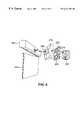
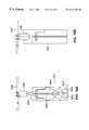
- FIG. 1is a perspective view of an exit fixture oriented to position an exit sign perpendicularly to a wall.
- FIG. 2is an exploded view of the fixture of FIG. 1 .
- FIG. 3is an exploded view of the fixture of FIG. 1 oriented to position the sign perpendicularly to a ceiling.
- FIG. 4is an exploded view of the fixture of FIG. 1 oriented to position the sign parallel to a wall.
- FIG. 5Ais a perspective view of a mounting base of the fixture of FIG. 1 .
- FIGS. 5B-5Eare top, bottom, front and side views of the mounting base of FIG. 5 A.
- FIG. 5Fis a sectional view of the mounting base of FIG. 5A taken along line 5 F— 5 F of FIG. 5 C.
- FIG. 6Ais a perspective view of a canopy of the fixture of FIG. 1 .
- FIGS. 6B and 6Care top and bottom views of the canopy of FIG. 6 A.
- FIG. 6Dis a sectional view of the canopy of FIG. 6A taken along line 6 D— 6 D of FIG. 6 B.
- FIG. 7Ais a perspective view of a housing of the fixture of FIG. 1 .
- FIGS. 7B-7Eare bottom, side, top, and end views of the housing of FIG. 7 A.
- FIG. 8Ais a perspective view of a cover of the housing of FIG. 7A
- FIG. 8B and 8Care bottom and top views of the cover of FIG. 8 A.
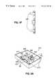
- FIG. 9Ais a perspective view of a plug.
- FIG. 9B and 9Care top and side views of the plug of FIG. 9 A.
- FIG. 10is a perspective view of the cover of FIG. 8A being placed on the housing of FIG. 7 A and the positioning of two plugs from FIG. 9 A.
- FIG. 11is a perspective view of a lens panel of the fixture of FIG. 1 .
- FIGS. 12A-12Care end views of a ceiling mount configuration, an end mount configuration, and a wall mount configuration for the fixture of FIG. 1 .
- FIGS. 13A and 13Bare enlarged views of a female end and a male end of a locking T-connector which connects the canopy to the housing.
- FIG. 14is an exploded view of the housing of FIG. 7A, its internal components, the plugs of FIG. 9A, and the cover of FIG. 8 A.
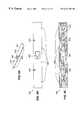
- FIG. 15is top view of a circuit board used to illuminate the sign.
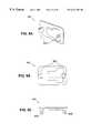
- FIG. 16Ais a side view of a lens panel and light source of the fixture of FIG. 1 .
- FIGS. 16B-16Dare enlarged views showing possible orientations between the light source and the lens panel of the fixture of FIG. 1 .
- an exit fixture 100may be secured to a wall or on a ceiling. As best shown in FIGS. 2-4, the fixture attaches to a junction box 200 which provides electrical power and further provides a stable connection point for the fixture.
- a mounting base 205 of the fixture 100is attached to junction box 200 by screws 210 .
- a canopy 215is attached to the mounting base 205 by tabs 218 (FIG. 6A) and latches 220 .
- a housing 225is attached to the canopy 215 by a locking T-connector 230 .
- a cover 232(FIG. 8A) closes the housing 225 .
- the housing 225can be end-mounted, as shown in FIGS. 1 and 2; ceiling-mounted, as shown in FIG. 3; or side-mounted, as shown in FIG. 4 .
- a lens panel 235is attached to the housing 225 by a snap fit. Different lens panels with different backings are available for the fixture.
- the mounting base 205includes attachment points 500 to which the junction box screws 210 attach.
- the mounting base 205also includes two latches 220 and two tab indentations 505 that secure the canopy 215 to the mounting base 205 .
- the mounting base 205also includes a screw receptacle 510 that receives a canopy screw (not shown).
- the canopy screwensures a secure mounting of the canopy 215 on the mounting base 205 .
- Structural reinforcements 515serve to strengthen the mounting base 205 .
- the canopy 215is attached to the mounting base 205 by latches 220 and tabs 218 .
- the canopy 215is tilted and the two tabs 218 are slipped underneath the tab indentations 505 of the mounting base 205 .
- the latches 220are depressed and the canopy 215 is pushed toward the mounting base 205 until the latches 220 snap into latch holes 605 on the canopy.
- a canopy screw(not shown) is screwed into a screw hole 610 in the canopy, and then into the screw receptacle 510 for the mounting base.
- the screwensures that the canopy 215 will not separate from the mounting base 205 .
- the latches 220are made from resilient material to ensure that the latches 220 remain in the latch holes 605 .
- the canopy 215is attached to the housing 225 by a locking T-connector 230 .
- the male end 615 of the locking T connector 230is on the canopy 215 .
- the interior of the canopyalso includes a wiring mount 620 , as well as four mounting arms 625 and alignment structures 630 for use in securing a backup power supply (e.g., a battery unit) within the canopy.
- a backup power supplye.g., a battery unit
- the housing 225includes two female ends 700 of the locking T-connector 230 , with a first female end 700 A being located on the end 705 of the housing to provide an end-mounted configuration, and a second female end 700 B being located on a side 710 of the housing to provide a side-mounted configuration.
- the female end 700 of the locking T-connector 230includes a larger T-shaped hole 715 and a smaller rectangular hole 720 .
- the housing 225also connects to the cover 232 (FIG. 8A) and the lens panel 235 .
- the housing 225includes four tabs 725 for connection to the cover 232 (FIG. 8 A).
- the housing 225includes a slot 730 , two retaining tabs 735 , and four lens stops 740 for connection to the lens panel 235 .
- the housingalso includes structural reinforcements 745 .
- the cover 232includes four tab indentations 805 , a female end 700 of a locking T-connector 230 (for providing a ceiling-mounted configuration), and two screw holes 810 .
- the cover 232is tilted and the four tab indentations 805 are slipped underneath the four tabs 725 of the housing 225 .
- the cover 232is then snapped into place. Once the cover 232 is in place, two screws are placed in the screw holes 810 to ensure the cover 232 does not separate from the housing 225 .
- the coveralso includes structural reinforcement 815 .
- a plug 900is used to cover an unused female end 700 of a locking T-connector 230 .
- the T-connector female endsare on either the cover 232 or the housing 225 .
- the plug 900includes two plastic hooks 905 which pass through the two holes 715 and 720 of the female end 700 and lock into place. When inserted, the plug 900 provides a flush cover over the female end 700 .
- FIG. 10shows the cover 232 installed on the housing 225 with the plugs 900 being inserted into the unused female ends 700 . Screws 1000 secure the cover 232 in place.
- the lens panel 235snaps into place in the slot 730 of the housing 225 and is held in place by the two retaining tabs 735 .
- the lens panel 235is inserted until it hits the lens stops 740 .
- the tabs 1100 on the top of the lens panel 235are positioned above the retaining tabs 735 of the housing 225 .
- the retaining tabs 735are made of a resilient material to allow insertion of the lens panel 235 .
- the lens panel 235is also constructed to permit illumination of the edges of the sign and the letters or symbols displayed on the sign.
- FIGS. 12A-12Cshow the three different mounting configurations possible with the fixture.
- FIG. 12Ashows an end view of a ceiling-mounted fixture
- FIG. 12Bshows an end view of an end-mounted fixture
- FIG. 12Cshows an end view of a side-mounted fixture.
- FIGS. 13A and 13Billustrate a locking T-connector 230 , with FIG. 13A showing the female end 700 and FIG. 13B showing the male end 615 .
- the raised T-portion 1300 of the male end 615is inserted into the larger T-shaped hole 715 .
- the canopy 215which includes the male end 615 , is then slid in the direction of the smaller hole 720 of the female end 700 of the T-connector until the ends snap together.
- the connectionis locked into place by the locking mechanism 1305 of the locking bar 1310 , which snaps into place in the smaller hole 720 of the female end 700 of the T-connector.
- the resilience of the locking bar 1310keeps the locking mechanism 1305 in place.
- the locking bar 1310is pulled so that the locking mechanism 1305 is removed from the smaller hole 910 .
- the canopy 215then is slid away from the smaller hole 720 .
- a circuit board 1400 positioned inside the housing 225provides illumination for the lens panel 235 .
- a battery 1405can also be placed in the housing 225 to provide illumination when primary power is interrupted.
- the cover 232is used to close the open side of the housing 225 .
- the circuit board 1400includes a set of light emitting diodes (LEDs) 1500 .
- the LEDs 1500are illuminated when the circuit board 1400 is connected to a power source using a connector 1505 .
- the light from the illuminated LEDs 1500is channeled through an opening 1600 in the lens panel 235 to illuminate the edges of the lens panel 235 as well as the letters, numbers or symbols appearing on the panel.
- the lens panel 235includes reflective material 1605 inside the lens panel 235 and reflective material 1605 on the edges 1610 of the lens panel 235 .
- the light emitted from the LEDsmay travel along many different paths before exiting from a face of the lens panel 235 . A portion of the light from the LEDs will travel directly to the face of the lens panel 235 . Other light from the LEDs will be reflected by the reflective material in the center of the lens panel 235 before reaching a face of the lens panel 235 .
- Still other lightmay be reflected by the reflective material along the edges of the lens panel 235 before reaching a face of the lens panel 235 .
- the face of the lens panel 235is ultimately illuminated by the sum of the light travelling along the different paths to the face of the lens panel 235 .
- FIGS. 16B-16Dother interfaces between the LEDs 1500 and the edge of the lens panel may also be used.
- FIG. 16Billustrates an edge of the lens panel whose contour matches the shape of the LEDs 1500 . This interface captures more of the light from the LEDs and channels it into the lens panel 235 .
- FIG. 16Cillustrates a third interface between the LEDs 1500 and the edge of the lens panel 235 .
- the generally rectangular receiving area along the edge of the lens panel 235receives light from the LEDs 1500 at different angles than the previous orientations.
- the bubble shape 1615 along the bottom of the rectangular groove in the receiving area of the edge of the lens panelincreases the amount of light that is directed to the reflective material 1605 in the center of the lens panel 235 .
- FIG. 16Dillustrates a fourth interface between the LEDs 1500 and the edge of the lens panel 235 .
- This configurationcombines a portion of the contour shape included in FIG. 16B with the generally rectangular shape of the interface of FIG. 16 C. This combination increase the amount of light which enters the edge of the lens panel 235 while increasing the amount of light available for reflection within the lens panel 235 .
- the various interfaces between the LEDs 1500 and the edge of the lens panel 235can be used to maximize the effectiveness of the exit sign for varying conditions.
Landscapes
- Engineering & Computer Science (AREA)
- General Engineering & Computer Science (AREA)
- Physics & Mathematics (AREA)
- General Physics & Mathematics (AREA)
- Business, Economics & Management (AREA)
- Emergency Management (AREA)
- Architecture (AREA)
- Optics & Photonics (AREA)
- Illuminated Signs And Luminous Advertising (AREA)
- Connector Housings Or Holding Contact Members (AREA)
Abstract
Description
Claims (30)
Priority Applications (2)
| Application Number | Priority Date | Filing Date | Title |
|---|---|---|---|
| US09/196,785US6241369B1 (en) | 1998-11-20 | 1998-11-20 | Quick mount fixture |
| CA002270725ACA2270725C (en) | 1998-11-20 | 1999-04-29 | Quick mount fixture |
Applications Claiming Priority (1)
| Application Number | Priority Date | Filing Date | Title |
|---|---|---|---|
| US09/196,785US6241369B1 (en) | 1998-11-20 | 1998-11-20 | Quick mount fixture |
Publications (1)
| Publication Number | Publication Date |
|---|---|
| US6241369B1true US6241369B1 (en) | 2001-06-05 |
Family
ID=22726798
Family Applications (1)
| Application Number | Title | Priority Date | Filing Date |
|---|---|---|---|
| US09/196,785Expired - LifetimeUS6241369B1 (en) | 1998-11-20 | 1998-11-20 | Quick mount fixture |
Country Status (2)
| Country | Link |
|---|---|
| US (1) | US6241369B1 (en) |
| CA (1) | CA2270725C (en) |
Cited By (59)
| Publication number | Priority date | Publication date | Assignee | Title |
|---|---|---|---|---|
| US6511195B2 (en)* | 2001-05-17 | 2003-01-28 | Fonderal S.R.L. | Street lamp to carry a luminous plate and for lighting |
| US20030066220A1 (en)* | 2001-08-18 | 2003-04-10 | Velez Michael A. | Visual display unit |
| US20040011936A1 (en)* | 2001-05-22 | 2004-01-22 | Etienne Cousin | Assembly for mounting a self-supporting spotlight on a stretched ceiling |
| US20040118026A1 (en)* | 2002-12-23 | 2004-06-24 | Wen-Chun Yeh | Side-beam reflecting billboard structure |
| US20040150996A1 (en)* | 2000-12-28 | 2004-08-05 | Sun Ming-Shen Martin | Display structure |
| US20050054098A1 (en)* | 2003-06-27 | 2005-03-10 | Sanjay Mistry | Postpartum cells derived from umbilical cord tissue, and methods of making and using the same |
| US7047679B2 (en) | 2002-10-28 | 2006-05-23 | L. L. Culmat, L.P. | Molded sign facing plate |
| US20070236941A1 (en)* | 2006-02-14 | 2007-10-11 | Mark Logan | Illuminated sign insert |
| US7350327B1 (en)* | 2004-01-22 | 2008-04-01 | Abl Ip Holding, Llc | Mounting devices for exit signs and other fixtures |
| US7547122B1 (en) | 2005-12-27 | 2009-06-16 | Jimway Inc. | Area security light with adaptable mounting hardware |
| US20090322240A1 (en)* | 2008-06-25 | 2009-12-31 | Topanga Technologies, Inc. | Electrodeless lamps with externally-grounded probes and improved bulb assemblies |
| USD611547S1 (en)* | 2008-05-20 | 2010-03-09 | Thomas & Betts International, Inc. | Exit sign |
| US20100134008A1 (en)* | 2008-06-25 | 2010-06-03 | Topanga Technologies, Inc. | Electrodeless lamps with grounded coupling elements and improved bulb assemblies |
| US20100134013A1 (en)* | 2008-11-24 | 2010-06-03 | Topanga Technologies, Inc. | Method and system for adjusting the frequency of a resonator assembly for a plasma lamp |
| USD621990S1 (en) | 2009-05-15 | 2010-08-17 | Topanga Technologies, Inc. | Electrode-less lamp with base |
| USD621994S1 (en) | 2009-01-29 | 2010-08-17 | Topanga Technologies, Inc. | Cobra head lamp with small form factor electrodeless bulb |
| USD625454S1 (en) | 2009-01-10 | 2010-10-12 | Topanga Technologies, Inc. | Street lamp post with small form factor bulb |
| USD625363S1 (en)* | 2008-11-07 | 2010-10-12 | Je Woo Corporation, Ltd., Hui Yang | Illuminated exit sign |
| US7845103B2 (en) | 2006-02-14 | 2010-12-07 | Acuity Brands, Inc. | Illuminated sign mounting structure |
| US20110204808A1 (en)* | 2009-03-09 | 2011-08-25 | Topanga Technologies, Inc. | Method and system for replacing a plasma lamp from a resonator assembly |
| US20110204784A1 (en)* | 2009-06-12 | 2011-08-25 | Topanga Technologies, Inc. | Plasma Lamp with Dielectric Waveguide Body Having Shaped Configuration |
| USD653362S1 (en) | 2009-01-26 | 2012-01-31 | Topanga Technologies, Inc. | Electro-less lamp assembly |
| USD653363S1 (en) | 2009-03-09 | 2012-01-31 | Topanga Technologies, Inc. | High intensity plasma lamp with fins |
| US8294368B2 (en) | 2008-06-25 | 2012-10-23 | Topanga Technologies, Inc. | Electrodeless lamps with grounded coupling elements |
| US8427067B2 (en) | 2005-10-04 | 2013-04-23 | Topanga Technologies, Inc. | External resonator electrode-less plasma lamp and method of exciting with radio-frequency energy |
| US8545067B2 (en) | 2009-03-09 | 2013-10-01 | Topanga Technologies, Inc. | Small form factor durable street lamp and method |
| WO2013156414A1 (en)* | 2012-04-16 | 2013-10-24 | Hanning & Kahl Gmbh & Co. Kg | Guidance system that is integratable into the ground |
| US20130329459A1 (en)* | 2011-02-08 | 2013-12-12 | GE Lighting Solutions, LLC | Blade of light luminaire |
| US20140003041A1 (en)* | 2010-11-01 | 2014-01-02 | Quarkstar Llc | Solid state bidirectional light sheet having vertical orientation |
| US8833996B2 (en) | 2012-09-13 | 2014-09-16 | Quarkstar Llc | Illumination systems providing direct and indirect illumination |
| US8899808B2 (en) | 2011-08-08 | 2014-12-02 | Quarkstar Llc | Lightguide luminaire module for direct and indirect illumination |
| US9081125B2 (en) | 2011-08-08 | 2015-07-14 | Quarkstar Llc | Illumination devices including multiple light emitting elements |
| US9099291B2 (en) | 2013-06-03 | 2015-08-04 | Topanga Usa, Inc. | Impedance tuning of an electrode-less plasma lamp |
| US9177779B1 (en) | 2009-06-15 | 2015-11-03 | Topanga Usa, Inc. | Low profile electrodeless lamps with an externally-grounded probe |
| FR3020709A1 (en)* | 2014-05-05 | 2015-11-06 | Cooper Technologies Co | FIXING ARRANGEMENT FOR A SIGNALING ELEMENT DISPLAY DEVICE |
| US9206956B2 (en) | 2013-02-08 | 2015-12-08 | Quarkstar Llc | Illumination device providing direct and indirect illumination |
| US9224568B2 (en) | 2009-06-15 | 2015-12-29 | Topanga Usa | Arc tube device and stem structure for electrodeless plasma lamp |
| US9335462B2 (en) | 2013-07-18 | 2016-05-10 | Quarkstar Llc | Luminaire module with multiple light guide elements |
| US9354377B2 (en) | 2013-09-17 | 2016-05-31 | Quarkstar Llc | Light guide illumination device with light divergence modifier |
| US9392752B2 (en) | 2014-05-13 | 2016-07-19 | Topanga Usa, Inc. | Plasma growth lamp for horticulture |
| US9410680B2 (en) | 2013-04-19 | 2016-08-09 | Quarkstar Llc | Illumination devices with adjustable optical elements |
| ITUB20152072A1 (en)* | 2015-07-10 | 2017-01-10 | Beghelli Spa | FIXING SYSTEM FOR EMERGENCY LIGHTING APPLIANCES |
| US9557018B2 (en) | 2011-02-22 | 2017-01-31 | Quarkstar Llc | Solid state lamp using light emitting strips |
| US20170198893A1 (en)* | 2016-01-07 | 2017-07-13 | Robert A. Sonneman | Method and apparatus for hanging lighting fixtures |
| US9746173B2 (en) | 2012-09-13 | 2017-08-29 | Quarkstar Llc | Illumination devices including enclosure panels with luminaire modules |
| US9851569B2 (en) | 2015-11-06 | 2017-12-26 | Microsoft Technology Licensing, Llc | Mounting apparatus for head-mounted display device |
| US10041662B2 (en) | 2016-11-09 | 2018-08-07 | Robert A. Sonneman | Light bar for a lighting system |
| US10107456B2 (en) | 2011-02-22 | 2018-10-23 | Quarkstar Llc | Solid state lamp using modular light emitting elements |
| US10151466B2 (en) | 2016-11-09 | 2018-12-11 | Contemporary Visions, LLC | Laterally supported lights |
| US10174923B2 (en) | 2016-11-09 | 2019-01-08 | Contemporary Visions, LLC | Hanger for a modular lighting system having a main body with two channels to accommodate two segments of a power bar |
| US10184645B2 (en) | 2016-11-09 | 2019-01-22 | Contemporary Visions, LLC | Cylindrical housing for modular lighting system |
| US10281126B2 (en) | 2016-11-09 | 2019-05-07 | Contemporary Visions, LLC | Power bar hanger for modular lighting system |
| US10359182B2 (en) | 2016-11-09 | 2019-07-23 | Contemporary Visions, LLC | Ring power bar hanger for modular lighting fixture |
| USD860323S1 (en)* | 2017-06-08 | 2019-09-17 | Crestron Electronics, Inc. | Wall mounted sign |
| EP3582211A1 (en)* | 2018-06-13 | 2019-12-18 | Inlight GmbH & Co. KG | Lighting, in particular escape route lighting |
| USD870814S1 (en)* | 2017-06-08 | 2019-12-24 | Crestron Electronics, Inc. | Ceiling mounted sign |
| IT202000005149A1 (en)* | 2020-03-11 | 2021-09-11 | Schneider Electric Ind Italia S P A | SIGNALING APPARATUS |
| EP3968312A1 (en)* | 2020-09-15 | 2022-03-16 | Legrand France | Standalone safety unit |
| US20220285924A1 (en)* | 2018-10-30 | 2022-09-08 | Scott Norris | Method for connecting a ceiling mounted fixture to an electrical junction box |
Citations (19)
| Publication number | Priority date | Publication date | Assignee | Title |
|---|---|---|---|---|
| US2578008A (en) | 1945-12-19 | 1951-12-11 | Tinnerman Products Inc | Fastening device |
| US2639311A (en)* | 1949-06-28 | 1953-05-19 | Gen Electric | Fastening device for shield cans |
| US2994148A (en)* | 1959-01-21 | 1961-08-01 | Mcphilben Mfg Co Inc | Directional luminaire |
| US3798584A (en)* | 1972-05-22 | 1974-03-19 | J Person | Quick connect ceiling electrical fixture mounting |
| US3931689A (en)* | 1974-06-12 | 1976-01-13 | Dual-Lite Company | Illuminated sign housing construction |
| US4385343A (en)* | 1978-12-26 | 1983-05-24 | Plumly George W | Edge lighted devices |
| US4415217A (en)* | 1981-07-16 | 1983-11-15 | Raychem Corporation | Cable joining connector and method |
| US5027258A (en)* | 1989-06-19 | 1991-06-25 | Inotec Gmbh Gesellschaft Fur Innovative Technik | Display unit |
| US5102275A (en) | 1990-10-29 | 1992-04-07 | Construction Fasteners, Inc. | Deck plate and assembly |
| US5138116A (en) | 1989-08-16 | 1992-08-11 | Pioneer Electronic Corporation | Mounting device for electronic component |
| US5190365A (en)* | 1991-10-16 | 1993-03-02 | Apple Computer, Inc. | Backlighting for liquid crystal displays |
| US5207535A (en) | 1991-10-30 | 1993-05-04 | Saab Thomas L | Push-on gripper plate for use with rock bolts |
| US5239450A (en)* | 1991-03-28 | 1993-08-24 | Wall Stephen F | Illuminated button with interchangeable image |
| US5267404A (en) | 1992-10-21 | 1993-12-07 | Kizy John J | Display |
| US5272605A (en) | 1990-09-20 | 1993-12-21 | Dual-Lite Manufacturing, Inc. | Canopy mounting device for exit signs and the like |
| US5376020A (en) | 1993-02-24 | 1994-12-27 | Jones; John E. | Canopy for an exit light |
| US5526251A (en) | 1994-11-22 | 1996-06-11 | National Service Industries, Inc. | Emergency lighting connections |
| US5640792A (en) | 1995-06-07 | 1997-06-24 | National Service Industries, Inc. | Lighting fixtures |
| US5735498A (en) | 1996-05-07 | 1998-04-07 | Cooper Industries, Inc. | Apparatus for mounting an emergency sign to a support |
- 1998
- 1998-11-20USUS09/196,785patent/US6241369B1/ennot_activeExpired - Lifetime
- 1999
- 1999-04-29CACA002270725Apatent/CA2270725C/ennot_activeExpired - Fee Related
Patent Citations (19)
| Publication number | Priority date | Publication date | Assignee | Title |
|---|---|---|---|---|
| US2578008A (en) | 1945-12-19 | 1951-12-11 | Tinnerman Products Inc | Fastening device |
| US2639311A (en)* | 1949-06-28 | 1953-05-19 | Gen Electric | Fastening device for shield cans |
| US2994148A (en)* | 1959-01-21 | 1961-08-01 | Mcphilben Mfg Co Inc | Directional luminaire |
| US3798584A (en)* | 1972-05-22 | 1974-03-19 | J Person | Quick connect ceiling electrical fixture mounting |
| US3931689A (en)* | 1974-06-12 | 1976-01-13 | Dual-Lite Company | Illuminated sign housing construction |
| US4385343A (en)* | 1978-12-26 | 1983-05-24 | Plumly George W | Edge lighted devices |
| US4415217A (en)* | 1981-07-16 | 1983-11-15 | Raychem Corporation | Cable joining connector and method |
| US5027258A (en)* | 1989-06-19 | 1991-06-25 | Inotec Gmbh Gesellschaft Fur Innovative Technik | Display unit |
| US5138116A (en) | 1989-08-16 | 1992-08-11 | Pioneer Electronic Corporation | Mounting device for electronic component |
| US5272605A (en) | 1990-09-20 | 1993-12-21 | Dual-Lite Manufacturing, Inc. | Canopy mounting device for exit signs and the like |
| US5102275A (en) | 1990-10-29 | 1992-04-07 | Construction Fasteners, Inc. | Deck plate and assembly |
| US5239450A (en)* | 1991-03-28 | 1993-08-24 | Wall Stephen F | Illuminated button with interchangeable image |
| US5190365A (en)* | 1991-10-16 | 1993-03-02 | Apple Computer, Inc. | Backlighting for liquid crystal displays |
| US5207535A (en) | 1991-10-30 | 1993-05-04 | Saab Thomas L | Push-on gripper plate for use with rock bolts |
| US5267404A (en) | 1992-10-21 | 1993-12-07 | Kizy John J | Display |
| US5376020A (en) | 1993-02-24 | 1994-12-27 | Jones; John E. | Canopy for an exit light |
| US5526251A (en) | 1994-11-22 | 1996-06-11 | National Service Industries, Inc. | Emergency lighting connections |
| US5640792A (en) | 1995-06-07 | 1997-06-24 | National Service Industries, Inc. | Lighting fixtures |
| US5735498A (en) | 1996-05-07 | 1998-04-07 | Cooper Industries, Inc. | Apparatus for mounting an emergency sign to a support |
Cited By (132)
| Publication number | Priority date | Publication date | Assignee | Title |
|---|---|---|---|---|
| US20040150996A1 (en)* | 2000-12-28 | 2004-08-05 | Sun Ming-Shen Martin | Display structure |
| US7004613B2 (en)* | 2000-12-28 | 2006-02-28 | Au Optronics Corp. | Display structure |
| US6511195B2 (en)* | 2001-05-17 | 2003-01-28 | Fonderal S.R.L. | Street lamp to carry a luminous plate and for lighting |
| US20040011936A1 (en)* | 2001-05-22 | 2004-01-22 | Etienne Cousin | Assembly for mounting a self-supporting spotlight on a stretched ceiling |
| US7070306B2 (en)* | 2001-05-22 | 2006-07-04 | Newmat, S.A. | Assembly for mounting a self-supporting spotlight on a stretched ceiling |
| US20030066220A1 (en)* | 2001-08-18 | 2003-04-10 | Velez Michael A. | Visual display unit |
| US6857212B2 (en)* | 2001-08-18 | 2005-02-22 | Michael Velez | Visual display unit |
| US7047679B2 (en) | 2002-10-28 | 2006-05-23 | L. L. Culmat, L.P. | Molded sign facing plate |
| US20040118026A1 (en)* | 2002-12-23 | 2004-06-24 | Wen-Chun Yeh | Side-beam reflecting billboard structure |
| US20050054098A1 (en)* | 2003-06-27 | 2005-03-10 | Sanjay Mistry | Postpartum cells derived from umbilical cord tissue, and methods of making and using the same |
| US7350327B1 (en)* | 2004-01-22 | 2008-04-01 | Abl Ip Holding, Llc | Mounting devices for exit signs and other fixtures |
| US8427067B2 (en) | 2005-10-04 | 2013-04-23 | Topanga Technologies, Inc. | External resonator electrode-less plasma lamp and method of exciting with radio-frequency energy |
| US7547122B1 (en) | 2005-12-27 | 2009-06-16 | Jimway Inc. | Area security light with adaptable mounting hardware |
| US7739818B2 (en) | 2006-02-14 | 2010-06-22 | ABL IP Lighting, LLC | Illuminated sign insert |
| US7845103B2 (en) | 2006-02-14 | 2010-12-07 | Acuity Brands, Inc. | Illuminated sign mounting structure |
| US20070236941A1 (en)* | 2006-02-14 | 2007-10-11 | Mark Logan | Illuminated sign insert |
| USD611547S1 (en)* | 2008-05-20 | 2010-03-09 | Thomas & Betts International, Inc. | Exit sign |
| US8766539B2 (en) | 2008-06-25 | 2014-07-01 | Topanga Usa, Inc. | Electrodeless lamps with grounded coupling elements and improved bulb assemblies |
| US8884518B2 (en) | 2008-06-25 | 2014-11-11 | Topanga Usa, Inc. | Electrodeless lamps with externally-grounded probes and improved bulb assemblies |
| US20090322240A1 (en)* | 2008-06-25 | 2009-12-31 | Topanga Technologies, Inc. | Electrodeless lamps with externally-grounded probes and improved bulb assemblies |
| US8674603B2 (en) | 2008-06-25 | 2014-03-18 | Topanga Technologies, Inc. | Electrodeless lamps with grounded coupling elements |
| US8283866B2 (en) | 2008-06-25 | 2012-10-09 | Topanga Technologies, Inc. | Electrodeless lamps with externally-grounded probes and improved bulb assemblies |
| US7830092B2 (en) | 2008-06-25 | 2010-11-09 | Topanga Technologies, Inc. | Electrodeless lamps with externally-grounded probes and improved bulb assemblies |
| US8294368B2 (en) | 2008-06-25 | 2012-10-23 | Topanga Technologies, Inc. | Electrodeless lamps with grounded coupling elements |
| US20100134008A1 (en)* | 2008-06-25 | 2010-06-03 | Topanga Technologies, Inc. | Electrodeless lamps with grounded coupling elements and improved bulb assemblies |
| US20110037389A1 (en)* | 2008-06-25 | 2011-02-17 | Topanga Technologies, Inc. | Electrodeless lamps with externally-grounded probes and improved bulb assemblies |
| USD625363S1 (en)* | 2008-11-07 | 2010-10-12 | Je Woo Corporation, Ltd., Hui Yang | Illuminated exit sign |
| US8179047B2 (en) | 2008-11-24 | 2012-05-15 | Topanga Technologies, Inc. | Method and system for adjusting the frequency of a resonator assembly for a plasma lamp |
| US20100134013A1 (en)* | 2008-11-24 | 2010-06-03 | Topanga Technologies, Inc. | Method and system for adjusting the frequency of a resonator assembly for a plasma lamp |
| US8525412B2 (en) | 2008-11-24 | 2013-09-03 | Topanga Technologies, Inc. | Method and system for selectively tuning the frequency of a resonator assembly for a plasma lamp |
| USD625454S1 (en) | 2009-01-10 | 2010-10-12 | Topanga Technologies, Inc. | Street lamp post with small form factor bulb |
| USD671662S1 (en) | 2009-01-26 | 2012-11-27 | Topanga Technologies, Inc. | Electrode-less lamp assembly |
| USD653362S1 (en) | 2009-01-26 | 2012-01-31 | Topanga Technologies, Inc. | Electro-less lamp assembly |
| USD621994S1 (en) | 2009-01-29 | 2010-08-17 | Topanga Technologies, Inc. | Cobra head lamp with small form factor electrodeless bulb |
| USD665932S1 (en) | 2009-03-09 | 2012-08-21 | Topanga Technologies, Inc. | High intensity plasma lamp design with fins |
| US8282435B2 (en) | 2009-03-09 | 2012-10-09 | Topanga Technologies, Inc. | Method and system for replacing a plasma lamp from a resonator assembly |
| US8545067B2 (en) | 2009-03-09 | 2013-10-01 | Topanga Technologies, Inc. | Small form factor durable street lamp and method |
| US20110204808A1 (en)* | 2009-03-09 | 2011-08-25 | Topanga Technologies, Inc. | Method and system for replacing a plasma lamp from a resonator assembly |
| USD653363S1 (en) | 2009-03-09 | 2012-01-31 | Topanga Technologies, Inc. | High intensity plasma lamp with fins |
| USD627918S1 (en) | 2009-05-15 | 2010-11-23 | Topanga Technologies, Inc. | Electrode-less lamp with base |
| USD621990S1 (en) | 2009-05-15 | 2010-08-17 | Topanga Technologies, Inc. | Electrode-less lamp with base |
| US8344625B2 (en) | 2009-06-12 | 2013-01-01 | Topanga Technologies, Inc. | Plasma lamp with dielectric waveguide body having shaped configuration |
| US20110204784A1 (en)* | 2009-06-12 | 2011-08-25 | Topanga Technologies, Inc. | Plasma Lamp with Dielectric Waveguide Body Having Shaped Configuration |
| US9177779B1 (en) | 2009-06-15 | 2015-11-03 | Topanga Usa, Inc. | Low profile electrodeless lamps with an externally-grounded probe |
| US9224568B2 (en) | 2009-06-15 | 2015-12-29 | Topanga Usa | Arc tube device and stem structure for electrodeless plasma lamp |
| US10132466B2 (en) | 2010-11-01 | 2018-11-20 | Quarkstar Llc | Bidirectional light emitting diode light sheet |
| US20140003041A1 (en)* | 2010-11-01 | 2014-01-02 | Quarkstar Llc | Solid state bidirectional light sheet having vertical orientation |
| US8979309B2 (en)* | 2010-11-01 | 2015-03-17 | Quarkstar Llc | Ceiling illumination device with bidirectional LED light sheet |
| US9395478B2 (en)* | 2011-02-08 | 2016-07-19 | GE Lighting Solutions, LLC | Blade of light luminaire |
| US20130329459A1 (en)* | 2011-02-08 | 2013-12-12 | GE Lighting Solutions, LLC | Blade of light luminaire |
| US11821590B2 (en) | 2011-02-22 | 2023-11-21 | Quarkstar Llc | Solid state lamp using light emitting strips |
| US11333305B2 (en) | 2011-02-22 | 2022-05-17 | Quarkstar Llc | Solid state lamp using light emitting strips |
| US10634287B2 (en) | 2011-02-22 | 2020-04-28 | Quarkstar Llc | Solid state lamp using light emitting strips |
| US12259096B2 (en) | 2011-02-22 | 2025-03-25 | Quarkstar Llc | Solid state lamp using light emitting strips |
| US11920739B2 (en) | 2011-02-22 | 2024-03-05 | Quarkstar Llc | Solid state lamp using light emitting strips |
| US10634288B2 (en) | 2011-02-22 | 2020-04-28 | Quarkstar Llc | Solid state lamp using light emitting strips |
| US10690294B2 (en) | 2011-02-22 | 2020-06-23 | Quarkstar Llc | Solid state lamp using light emitting strips |
| US10288229B2 (en) | 2011-02-22 | 2019-05-14 | Quarkstar Llc | Solid state lamp using light emitting strips |
| US10107456B2 (en) | 2011-02-22 | 2018-10-23 | Quarkstar Llc | Solid state lamp using modular light emitting elements |
| US10859213B2 (en) | 2011-02-22 | 2020-12-08 | Quarkstar Llc | Solid state lamp using light emitting strips |
| US10962177B2 (en) | 2011-02-22 | 2021-03-30 | Quarkstar Llc | Solid state lamp using light emitting strips |
| US11009191B1 (en) | 2011-02-22 | 2021-05-18 | Quarkstar Llc | Solid state lamp using light emitting strips |
| US11015766B1 (en) | 2011-02-22 | 2021-05-25 | Quarkstar Llc | Solid state lamp using light emitting strips |
| US11603967B2 (en) | 2011-02-22 | 2023-03-14 | Quarkstar Llc | Solid state lamp using light emitting strips |
| US11598491B2 (en) | 2011-02-22 | 2023-03-07 | Quarkstar Llc | Solid state lamp using light emitting strips |
| US9557018B2 (en) | 2011-02-22 | 2017-01-31 | Quarkstar Llc | Solid state lamp using light emitting strips |
| US11060672B1 (en) | 2011-02-22 | 2021-07-13 | Quarkstar Llc | Solid state lamp using light emitting strips |
| US11359772B2 (en) | 2011-02-22 | 2022-06-14 | Quarkstar Llc | Solid state lamp using light emitting strips |
| US11098855B2 (en) | 2011-02-22 | 2021-08-24 | Quarkstar Llc | Solid state lamp using light emitting strips |
| US11339928B2 (en) | 2011-02-22 | 2022-05-24 | Quarkstar Llc | Solid state lamp using light emitting strips |
| US11703631B2 (en) | 2011-08-08 | 2023-07-18 | Quarkstar Llc | Illumination devices including multiple light emitting elements |
| US10823905B2 (en) | 2011-08-08 | 2020-11-03 | Quarkstar Llc | Illumination devices including multiple light emitting elements |
| US9081125B2 (en) | 2011-08-08 | 2015-07-14 | Quarkstar Llc | Illumination devices including multiple light emitting elements |
| US9028120B2 (en) | 2011-08-08 | 2015-05-12 | Quarkstar Llc | Illumination devices including multiple light emitting elements |
| US8899808B2 (en) | 2011-08-08 | 2014-12-02 | Quarkstar Llc | Lightguide luminaire module for direct and indirect illumination |
| US10859758B2 (en) | 2011-08-08 | 2020-12-08 | Quarkstar Llc | Illumination devices including multiple light emitting elements |
| WO2013156414A1 (en)* | 2012-04-16 | 2013-10-24 | Hanning & Kahl Gmbh & Co. Kg | Guidance system that is integratable into the ground |
| US8833996B2 (en) | 2012-09-13 | 2014-09-16 | Quarkstar Llc | Illumination systems providing direct and indirect illumination |
| US10190762B2 (en) | 2012-09-13 | 2019-01-29 | Quarkstar Llc | Devices for workspace illumination having a panel forming an enclosure and a plurality of light emitters with primary and secondary optics |
| US9746173B2 (en) | 2012-09-13 | 2017-08-29 | Quarkstar Llc | Illumination devices including enclosure panels with luminaire modules |
| US9846272B2 (en) | 2012-09-13 | 2017-12-19 | Quarkstar Llc | Illumination systems providing direct and indirect illumination |
| US9206956B2 (en) | 2013-02-08 | 2015-12-08 | Quarkstar Llc | Illumination device providing direct and indirect illumination |
| US9410680B2 (en) | 2013-04-19 | 2016-08-09 | Quarkstar Llc | Illumination devices with adjustable optical elements |
| US10180240B2 (en) | 2013-04-19 | 2019-01-15 | Quarkstar Llc | Illumination devices with adjustable optical elements |
| US9099291B2 (en) | 2013-06-03 | 2015-08-04 | Topanga Usa, Inc. | Impedance tuning of an electrode-less plasma lamp |
| US9459398B2 (en) | 2013-07-18 | 2016-10-04 | Quarkstar Llc | Illumination device in which source light injection is non-parallel to device's optical axis |
| US10838138B2 (en) | 2013-07-18 | 2020-11-17 | Quarkstar Llc | Luminaire module with multiple light guide elements |
| US9335462B2 (en) | 2013-07-18 | 2016-05-10 | Quarkstar Llc | Luminaire module with multiple light guide elements |
| US10132988B2 (en) | 2013-07-18 | 2018-11-20 | Quarkstar Llc | Luminaire module with multiple light guide elements |
| US10288798B2 (en) | 2013-07-18 | 2019-05-14 | Quarkstar Llc | Illumination device in which source light injection is non-parallel to device's optical axis |
| US9664839B2 (en) | 2013-09-17 | 2017-05-30 | Quarkstar Llc | Illumination device for direct-indirect illumination |
| US9557030B2 (en) | 2013-09-17 | 2017-01-31 | Quarkstar Llc | Light guide illumination device for direct-indirect illumination |
| US10725229B2 (en) | 2013-09-17 | 2020-07-28 | Quarkstar Llc | Illumination device for direct-indirect illumination |
| US10203446B2 (en) | 2013-09-17 | 2019-02-12 | Quarkstar Llc | Light guide illumination device with light divergence modifier |
| US10705284B2 (en) | 2013-09-17 | 2020-07-07 | Quarkstar Llc | Luminaire with luminaire module |
| US9354377B2 (en) | 2013-09-17 | 2016-05-31 | Quarkstar Llc | Light guide illumination device with light divergence modifier |
| US9891371B2 (en) | 2013-09-17 | 2018-02-13 | Quarkstar Llc | Light guide illumination device for direct-indirect illumination |
| US10495807B2 (en) | 2013-09-17 | 2019-12-03 | Quarkstar Llc | Light guide illumination device for direct-indirect illumination |
| US11693174B2 (en) | 2013-09-17 | 2023-07-04 | Quarkstar Llc | Illumination device for direct-indirect illumination |
| US11150400B2 (en) | 2013-09-17 | 2021-10-19 | Quarkstar Llc | Illumination device for direct-indirect illumination |
| US10094969B2 (en) | 2013-09-17 | 2018-10-09 | Quarkstar Llc | Illumination device for direct-indirect illumination |
| EP2942770A1 (en)* | 2014-05-05 | 2015-11-11 | Cooper Technologies Company | Arrangement for securing a device for displaying a signalling element |
| FR3020709A1 (en)* | 2014-05-05 | 2015-11-06 | Cooper Technologies Co | FIXING ARRANGEMENT FOR A SIGNALING ELEMENT DISPLAY DEVICE |
| US9392752B2 (en) | 2014-05-13 | 2016-07-19 | Topanga Usa, Inc. | Plasma growth lamp for horticulture |
| ITUB20152072A1 (en)* | 2015-07-10 | 2017-01-10 | Beghelli Spa | FIXING SYSTEM FOR EMERGENCY LIGHTING APPLIANCES |
| US9851569B2 (en) | 2015-11-06 | 2017-12-26 | Microsoft Technology Licensing, Llc | Mounting apparatus for head-mounted display device |
| US9777899B2 (en) | 2016-01-07 | 2017-10-03 | Robert A. Sonneman | Support for pendant clusters |
| US10288271B2 (en) | 2016-01-07 | 2019-05-14 | Contemporary Visions, LLC | Canopy for a modular lighting system |
| US20170198893A1 (en)* | 2016-01-07 | 2017-07-13 | Robert A. Sonneman | Method and apparatus for hanging lighting fixtures |
| US10060609B2 (en) | 2016-01-07 | 2018-08-28 | Contemporary Visions, LLC | Modular lighting system using hangers and power bars |
| US10151465B2 (en) | 2016-01-07 | 2018-12-11 | Contemporary Visions, LLC | Modular lighting system with a plurality of power bars |
| US10036541B2 (en) | 2016-01-07 | 2018-07-31 | Contemporary Visions, LLC | Canopy for a modular lighting system |
| US10018339B2 (en) | 2016-01-07 | 2018-07-10 | Robert A. Sonneman | Modular lighting system using hangers and power bars |
| US10156349B2 (en) | 2016-01-07 | 2018-12-18 | Contemporary Visions, LLC | Method and apparatus for hanging lighting fixtures |
| US9879845B2 (en)* | 2016-01-07 | 2018-01-30 | Robert A. Sonneman | Modular lighting system using hangers and power bars |
| US10527269B2 (en) | 2016-01-07 | 2020-01-07 | Contemporary Visions, LLC | Modular lighting system using hangers and power bars |
| US10203100B2 (en)* | 2016-01-07 | 2019-02-12 | Contemporary Visions, LLC | Method and apparatus for hanging lighting fixtures |
| US10174923B2 (en) | 2016-11-09 | 2019-01-08 | Contemporary Visions, LLC | Hanger for a modular lighting system having a main body with two channels to accommodate two segments of a power bar |
| US10359182B2 (en) | 2016-11-09 | 2019-07-23 | Contemporary Visions, LLC | Ring power bar hanger for modular lighting fixture |
| US10041662B2 (en) | 2016-11-09 | 2018-08-07 | Robert A. Sonneman | Light bar for a lighting system |
| US10184645B2 (en) | 2016-11-09 | 2019-01-22 | Contemporary Visions, LLC | Cylindrical housing for modular lighting system |
| US10281126B2 (en) | 2016-11-09 | 2019-05-07 | Contemporary Visions, LLC | Power bar hanger for modular lighting system |
| US10151466B2 (en) | 2016-11-09 | 2018-12-11 | Contemporary Visions, LLC | Laterally supported lights |
| USD870814S1 (en)* | 2017-06-08 | 2019-12-24 | Crestron Electronics, Inc. | Ceiling mounted sign |
| USD860323S1 (en)* | 2017-06-08 | 2019-09-17 | Crestron Electronics, Inc. | Wall mounted sign |
| EP3582211A1 (en)* | 2018-06-13 | 2019-12-18 | Inlight GmbH & Co. KG | Lighting, in particular escape route lighting |
| US20220285924A1 (en)* | 2018-10-30 | 2022-09-08 | Scott Norris | Method for connecting a ceiling mounted fixture to an electrical junction box |
| US11689005B2 (en)* | 2018-10-30 | 2023-06-27 | Scott Norris | Method for connecting a ceiling mounted fixture to an electrical junction box |
| EP3879515A1 (en)* | 2020-03-11 | 2021-09-15 | Schneider Electric Industrie Italia S.p.A. | Signaling apparatus |
| IT202000005149A1 (en)* | 2020-03-11 | 2021-09-11 | Schneider Electric Ind Italia S P A | SIGNALING APPARATUS |
| FR3114140A1 (en)* | 2020-09-15 | 2022-03-18 | Legrand France | Autonomous safety block |
| EP3968312A1 (en)* | 2020-09-15 | 2022-03-16 | Legrand France | Standalone safety unit |
Also Published As
| Publication number | Publication date |
|---|---|
| CA2270725A1 (en) | 2000-05-20 |
| CA2270725C (en) | 2003-12-02 |
Similar Documents
| Publication | Publication Date | Title |
|---|---|---|
| US6241369B1 (en) | Quick mount fixture | |
| US6239986B1 (en) | Housing body of electronic equipment | |
| US5387901A (en) | Led indicating light assembly for a computer housing | |
| US6457270B1 (en) | Universal emergency sign | |
| US6951406B2 (en) | Led task light | |
| US6539657B1 (en) | Universal edge-lit exit sign | |
| US5349134A (en) | Corner mounted wiring devices | |
| US5768814A (en) | Exit sign with removable emergency power pack module | |
| US8002447B2 (en) | Surface-mounted lighting fixture | |
| US7350327B1 (en) | Mounting devices for exit signs and other fixtures | |
| US20040184267A1 (en) | Lighting system and housing therefore | |
| US7739818B2 (en) | Illuminated sign insert | |
| US12092295B2 (en) | Light fixture connection system and optic holder | |
| US7845103B2 (en) | Illuminated sign mounting structure | |
| US7744255B2 (en) | Light-reflecting and light-shielding apparatus of computer panel | |
| US6053765A (en) | Electrical connector incorporating a light | |
| CN108488703A (en) | A kind of illumination module and illuminator | |
| JP4105366B2 (en) | Medical piping wiring connection terminal storage unit | |
| CN1223476A (en) | Battery holding structure for electronic equipment | |
| CN220321092U (en) | Plug-in type modularization equipment lamps and lanterns | |
| US20030201782A1 (en) | Test device for internet and telephone lines | |
| EP0932260A1 (en) | A communication system which can be mounted on a flush-mounted box in a wall | |
| JP2000076558A (en) | Indicator for disaster prevention equipment | |
| JP3787856B2 (en) | Source lamp lighting equipment | |
| JPH0347353Y2 (en) |
Legal Events
| Date | Code | Title | Description |
|---|---|---|---|
| AS | Assignment | Owner name:COOPER TECHNOLOGIES COMPANY, TEXAS Free format text:ASSIGNMENT OF ASSIGNORS INTEREST;ASSIGNOR:MACKIEWICZ, EDWIN THOMAS;REEL/FRAME:009599/0214 Effective date:19981119 | |
| STCF | Information on status: patent grant | Free format text:PATENTED CASE | |
| FPAY | Fee payment | Year of fee payment:4 | |
| CC | Certificate of correction | ||
| FPAY | Fee payment | Year of fee payment:8 | |
| FPAY | Fee payment | Year of fee payment:12 | |
| AS | Assignment | Owner name:EATON INTELLIGENT POWER LIMITED, IRELAND Free format text:ASSIGNMENT OF ASSIGNORS INTEREST;ASSIGNOR:COOPER TECHNOLOGIES COMPANY;REEL/FRAME:048207/0819 Effective date:20171231 | |
| AS | Assignment | Owner name:EATON INTELLIGENT POWER LIMITED, IRELAND Free format text:CORRECTIVE ASSIGNMENT TO CORRECT THE COVER SHEET TO REMOVE APPLICATION NO. 15567271 PREVIOUSLY RECORDED ON REEL 048207 FRAME 0819. ASSIGNOR(S) HEREBY CONFIRMS THE ASSIGNMENT;ASSIGNOR:COOPER TECHNOLOGIES COMPANY;REEL/FRAME:048655/0114 Effective date:20171231 |