US6240166B1 - LAN connection using analog modems via telephone wiring - Google Patents
LAN connection using analog modems via telephone wiringDownload PDFInfo
- Publication number
- US6240166B1 US6240166B1US09/207,650US20765098AUS6240166B1US 6240166 B1US6240166 B1US 6240166B1US 20765098 AUS20765098 AUS 20765098AUS 6240166 B1US6240166 B1US 6240166B1
- Authority
- US
- United States
- Prior art keywords
- communication
- voice band
- network
- communication device
- voice
- Prior art date
- Legal status (The legal status is an assumption and is not a legal conclusion. Google has not performed a legal analysis and makes no representation as to the accuracy of the status listed.)
- Expired - Lifetime
Links
Images


Classifications
- H—ELECTRICITY
- H04—ELECTRIC COMMUNICATION TECHNIQUE
- H04M—TELEPHONIC COMMUNICATION
- H04M11/00—Telephonic communication systems specially adapted for combination with other electrical systems
- H04M11/06—Simultaneous speech and data transmission, e.g. telegraphic transmission over the same conductors
- H04M11/062—Simultaneous speech and data transmission, e.g. telegraphic transmission over the same conductors using different frequency bands for speech and other data
Definitions
- the present inventionrelates to a computer communication system and more particularly to a modem communication system where modems communicate across standard telephone lines within a premises using frequency division multiplexing.
- PCsPersonal computers
- InternetInternet
- Modemsare used to convert between a computer's digital signals and analog signals that can be carried on the telephone network's analog transmission lines.
- DSPdigital signal processor
- ICintegrated circuit
- memorya memory
- codecincludes a digital to analog converter (D/A) and an analog to digital converter (A/D).
- D/Adigital to analog converter
- A/Danalog to digital converter
- the modemis typically coupled to a host computer bus through standard bus interface circuitry to thereby interact with a host computer.
- the host computerincludes a central processing unit (CPU) that generates data that is to be transmitted through the modem and to receive data that is passed through the modem.
- CPUcentral processing unit
- DSP based modemsgenerally operate by processing a relatively small number of samples from the input A/D converter and generating a similarly small number of samples to be output through the D/A converter. These systems are said to work on a “sample by sample” basis or a “symbol by symbol” basis, depending on the particular implementation. Such schemes have the benefit of minimal latency time, since the input is processed almost immediately. These schemes, however, require very high computing power which is typically provided by a dedicated DSP.
- modemshave been developed that operate using DSPs implemented in software.
- software DSPsenable sampling rates to substantially increase without a corresponding increase in hardware expenses
- these software DSPsoperate similar to standard hardware DSPs by sampling and transmitting signals at or slightly above the “voice band”.
- the voice bandis approximately 4 kHz and has been recognized as the voice band because telephone lines typically operate with exchange circuitry, e.g., a central office or private branch exchange (PBX), configured with low pass circuitry that cuts off signals that have been transmitted at frequencies above the voice band.
- PBXprivate branch exchange
- modem signalsare typically transmitted in the voice band and DSPs sample the signals at a minimal frequency rate, i.e., twice the rate of the highest freqency of the signal being sampled, or the “Nyquist rate”.
- the communication systemsometimes creates the communication channel with a telephone wire network that has no exchange circuitry and is completely within a premises.
- the first communication device and the second communication deviceeach comprise a voice band modem.
- the communication systemalso allows the first communication device to communicatively couple with at least one external communication device via another communications channel.
- the first communication devicecommunicates with the at least one external communication device transparently to the communications between the first communication device and the second communication device.
- the communication systemallows the first communication device to communicate with the second communication device outside of the voice band.
- the communication systemcould also include a first processor associated with the first communication device such that the first processor influences, via the communication channel, operation of peripheral devices that are coupled to a second processor associated with the second communication device.
- a usercan communicate between a first and a second computer system.
- the first computer systemhas a first voice-band modem and the second computer system has a second voice-band modem, the first voice-band modem and the second voice-band modem communicatively coupled across a telephone line network.
- the usercommunicates between the computer systems by configuring the first voice band modem to transmit and receive signals at frequencies both within and without the voice band, configuring the second voice band modem to transmit and receive signals at frequencies both within and without the voice band, transmitting signals from the first computer system to the second computer system across the telephone line network at a frequency outside of the voice band without interfering with voice band communications of the first computer system, and receiving, from the telephone line network, signals at the second computer system at the frequency outside of the voice band without interfering with voice band communications of the second computer system.
- the usercan communicate between systems by transmitting signals from the second computer system to the first computer system across the telephone line network at a frequency outside of the voice band without interfering with voice band communications of the second computer system, and receiving, from the telephone line network, signals at the first computer system at the frequency outside of the voice band without interfering with voice band communications of the first computer system. Further, the user communicates by controlling, with the first computer system and through communications across the telephone line network, peripheral devices attached to the second computer system, the communications passing transparently to other communications on the telephone line network.
- a communication systemin another embodiment according to principles of the present invention, includes a first voice band modem; a second voice band modem; a telephone wire network within a premises and without exchange circuitry within the premises.
- the first voice band modemis communicatively coupled to the second voice band modem via the telephone wire network such that the first voice band modem communicates, outside of the voice band, with the second voice band modem.
- the first voice band modemmay be communicatively coupled across another telephone wire network to another communication device for voice band communications.
- communication signals between the first voice band modem and the second voice band modemare multiplexed in the frequency domain as well as communication signals between the first voice band modem and an external communication device being multiplexed in the frequency domain.
- the first voice band modemoften communicates with an external communication device that is communicatively coupled to the first voice band modem on a communication network external to the telephone wire network within the premises, the communication occurring transparently to the communications between the first voice band modem and the second voice band modem.
- the first voice band modemcan be associated with a processor, wherein the processor is allowed to operate peripheral devices of another processor that is associated with the second voice band modem.
- a telephone line network systemincludes telephone lines configured to allow communications between network devices.
- a plurality of network devicesis communicatively coupled to the telephone lines with each of the plurality of network devices including a communication module that enables communication between at least two of the plurality of network devices.
- At least one communication channel on the telephone linesenables the communication between the at least two of the plurality of network devices.
- each of the plurality of network devicesincludes a control module that enables each network device to selectively communicate on the at least one communication channel.
- the communication modulecomprises detection circuitry that indicates appropriate communication channels that are to be activated for each of the plurality of network devices according to a mode of the standard telephone.
- the at least one communication channel of the telephone line network systemmay comprise a voice band channel and a non-voice band channel.
- FIG. 1Ais a block diagram of an exemplary network system having multiple network devices communicatively coupled to each other for communication on the network system.
- FIG. 1Bis a block diagram of an exemplary network device for communicating on a telephone line network.
- FIG. 1Cis a block diagram of exemplary detection circuits for telephone line-in-use, extension pick-up, and remote hang-up.
- FIG. 2is a block diagram of an exemplary computer network having multiple computer systems communicatively coupled to each other and to exchange circuitry for access to an Internet Service Provider and ultimately for connection to the Internet.
- FIG. 3is a block diagram of another exemplary computer network having multiple computer systems communicatively coupled to each other and to exchange circuitry.
- FIG. 4is a block diagram of an exemplary communication device according to principles of the present invention.
- FIG. 5is a block diagram of a transmit portion of a digital signal processor (DSP) of the communication device of FIG. 4 .
- DSPdigital signal processor
- FIG. 6is a block diagram of a receive portion of the DSP of the communication device of FIG. 4 .
- FIG. 7is a block diagram of a codec portion of the communication device of FIG. 4 .
- FIG. 8is a block diagram of an exemplary computer system for practicing preferred embodiments of the present invention.
- FIG. 1Ais a block diagram of an exemplary network system 100 having multiple network devices 102 communicatively coupled to each other for communication on the network system 100 .
- the network system 100operates across telephone lines 104 and an independent telephone network 106 .
- Communicatively coupled to the telephone lines 104is a standard telephone 108 having telephone circuitry for entering various modes, e.g., on hook, off hook, line-in-use, etc.
- On hook moderepresents the telephone 108 when it does not utilize any of the bandwidth available on the telephone lines 104 .
- Off hook moderepresents that mode in which some bandwidth on the telephone line 104 is made available for the telephone 108 to use for communication across the telephone lines 104 and possibly the telephone network 106 .
- line-in-use modeis that mode when the telephone 108 actually makes use of the available bandwidth existing in the off hook mode.
- the network devices 102are configured such that they can communicate with one another either across the telephone lines 104 only, or across both the telephone lines 104 and the telephone network 106 . In this manner, the network devices 102 provide one of the advantages of the present invention.
- the telephone lines 104can be used by the network devices 102 to communicate by sending communication signals at full bandwidth, or having a portion of the bandwidth released, such as the voice band for use by the telephone 108 while multiple network devices 102 continue to communicate using a frequency other than the voice band.
- a single network device 102can operate using multiple bandwidths when the bandwidth is divided into multiple communication channels such as the voice band and a high band. This operation at multiple bandwidths is particularly useful when the network device 102 creates a communication channel across the telephone network 106 for communication at the voice band and also creates another communication channel across the telephone lines 104 for communication above the voice band.
- network devices 102rather than communicating directly across the telephone network 106 , can communicate using a cable box 110 to access other network devices 102 .
- network devices 102having advantages such as multiple bandwidth operation are still available when the network system 100 includes the cable box 110 .
- FIG. 1Bis a block diagram of an exemplary network device 102 for communicating on a telephone line network.
- the network device 102is interface circuitry 112 for accepting communication signals from a telephone line.
- the interface circuitry 112allows the network device 102 to communicate with at least one communication channel on the telephone line.
- the network device 102could be configured to communicate with a single channel that utilizes the full bandwidth of the telephone line.
- the network device 102could be configured to communicate with multiple channels that each communicate using a portion of the bandwidth.
- the network device 102could communicate with multiple channels that remain after releasing one of the channels in the bandwidth.
- the interface circuitry 112is configured to recognize signals from the telephone line.
- a signal processor 114is communicatively coupled to the interface circuitry 112 to process communication signals from the telephone line.
- the signal processor 114includes circuitry for processing communication signals from the various communication channels within the bandwidth of the telephone line.
- the signal processor 114could be configured to operate using a single communication channel comprising the whole bandwidth of the telephone line.
- the signal processor 114could be configured with circuitry for dividing the bandwidth into signals available from only certain communication channels on the telephone line.
- the signal processor 114enables communications across the telephone line according to communication parameters required by the network devices 102 with which the signal processor 114 is designed to communicate.
- control circuitry 116is included in order to appropriately process the communication signals of the communication channel(s) on the telephone line.
- numerous communication linescould be used to pass the communication signals of the communication channels to additional communication circuitry, as illustrated in the network device 102 of FIG. 1B, two communication lines, representing communication channels, are used to pass communication signals to appropriate circuitry such as a processor (not shown) in a computer system.
- FIG. 1Cis a block diagram of exemplary detection circuits 118 for telephone line-in-use, extension pick-up, and remote hang-up.
- the control circuitry 116operates according to whether a telephone line-in-use (LIU) signal, an extension pick-up (PU) signal, or a remote hang-up (HU) signal is detected.
- LIUtelephone line-in-use
- PUextension pick-up
- HUremote hang-up
- the control circuitry 116enables the network system 100 to detect actions on the telephone lines 104 that could impact operation of one or more of the network devices 102 . For example, if the network device 102 were an answering machine, the answering machine should cease operation when the telephone 108 is picked up by a user, thereby enabling uninterrupted telephone voice communication.
- the answering machinerequires circuitry to detect when the remote user hangs up so that it can cease its recording operations.
- the network device 102is a modem
- the modemmust detect whether a desired communication channel of the telephone line is already in use prior to attempting communications on that communication channel so that the modem can select another, unused communication channel, and avoid interruptions of communications on the communication channel.
- the control circuitry 116could be configured to recognize other signals and those other signals could influence the design of the detection circuits 118 .
- the detection circuitry 118provides the control circuitry 116 with information that allows the control circuitry 116 to determine which communication channels are to be added to the bandwidth, to be released from the bandwidth, or to remain in the bandwidth.
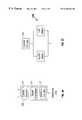
- FIG. 2is a block diagram of an exemplary computer network 200 having multiple computer systems 202 and 204 communicatively coupled to each other and to exchange circuitry 206 for access to an Internet Service Provider (ISP) 208 and ultimately for connection to the Internet.
- the computer systems 202 and 204are similar to the computer system 800 (see FIG. 8) and are communicatively coupled via a communication channel 210 so that communication devices such as modems (not shown) in each of the computer systems 202 , 204 provide communications across the communication channel 210 .
- the computer system 204 of the computer network 200is illustrated as being communicatively coupled to the exchange circuitry 206 for communication with the ISP 208 and the Internet.
- the exchange circuitry 206is circuitry that is typically found in either a private telephone network or at a local telephone office.
- Private telephone networksoften include a private branch exchange (PBX) to share a certain number of outside lines for making telephone calls external to the PBX. If the PBX is located at the local telephone office, it is referred to as a centrex (central office exchange service) and all switching occurs at the local telephone office instead of within the premises of the private telephone network.
- Telephone networks that provide access to additional telephone networks beyond a local/private premisesmust include exchange circuitry such as a PBX or the like. Most if not all telephone networks include exchange circuitry at some level. For example, local or private networks such as a home telephone line network do not include exchange circuitry at the local or private level, however, even a home telephone line network confronts exchange circuitry when a telephone call is made on the home telephone line network.
- the exchange circuitry 206provides the computer systems 202 , 204 access to the ISP 208 and the Internet. This access is typically accomplished via telephone lines with modems at each of the computer systems 202 , 204 providing the communication between the respective computer system 202 , 204 and to the exchange circuitry 206 .
- the computer network 200may be created, in part, with standard telephone lines between modems in the computer systems 202 , 204 .
- the modems of the computer systems 202 , 204operate without adversely affecting communication signals outside the communication channel 210 .
- FIG. 3is a block diagram of another exemplary computer network 300 having multiple computer systems 302 and 304 communicatively coupled to each other and to exchange circuitry 306 .
- Computer systems 302 and 304communicate with each other and with exchange circuitry 306 to access external communication channels, e.g., external telephone networks.
- the computer network 300operates with communication devices, such as modems (not shown), in each of the computer systems 302 , 304 , and, in this embodiment, transfers communication signals using telephone lines 308 . However, even if all communication signals are actually transferred across the telephone lines 308 , a logical communication channel 310 is created between the computer systems 302 and 304 .
- This logical communication channel 310represents a local network that provides each computer system 302 , 304 access to the peripherals on the other system.
- the computer system 302may choose to print from a printer that is mechanically coupled to the computer system 304 . Further, while printing, the computer system 302 may maintain a previously established communication channel to the Internet through the exchange circuitry 306 and allow the computer system 304 to access this communication channel without detrimentally affecting communications on the channel.
- the computer network 300communicates with the communication devices or modems of the computer systems 302 and 304 .
- FIG. 4is a block diagram of an exemplary communication device 400 according to principles of the present invention.
- the communication device 400 described hereinis a modem, however, it should be noted that the communication device 400 could be any device that enables computer systems to communicate across communication channels.
- the communication device 400includes a digital signal processor (DSP) 402 , a codec (compressor/decompressor) 404 , and a digital access arrangement (DAA) 406 .
- DSPdigital signal processor
- the DSP 402enables communication signals to pass to or from the DSP 402 while retaining the frequency spectrum of the original communication signal.
- DSP 402is designed to recognize frequencies both above and below the voice band frequencies through frequency division multiplexing.
- this designallows communication devices, e.g., modems, to communicate at both voice band and higher frequencies.
- modems according to the present inventioncan communicate at standard voice band frequencies and at frequencies well above the voice band. This allows modems to communicate at each level of a telephone network, each level being delimited by exchange circuitry or the like.
- the modemswhen modems communicate on a telephone network without exchange circuitry, e.g., a telephone line network within a home or residence, the modems can use a frequency greater than the voice band to communicate with other modems located on the home telephone network and can also use voice band frequency to communicate with modems located outside the home telephone network.
- the communication device 400provides the ability to communicate with other communication devices on a network bounded by exchange circuitry as well as to communicate with other communication devices exterior to the exchange circuitry.
- FIG. 5is a block diagram of a transmit portion 500 of the digital signal processor (DSP) 402 of the communication device 400 .
- the transmit portion 500receives both voice band signals 502 and other signals through the DSP 402 and combines those signals with a summer 504 for transmission on a single communication channel to the codec 404 .
- a transmitter 506 and an up converter 508assure that non-voice band signals are transmitted at a high frequency that is easily distinguishable from the voice band signals 502 when the combined signal is received at another DSP.
- FIG. 6is a block diagram of a receive portion 600 of the DSP 402 of the communication device 400 .
- the receive portion 600receives signals from the codec 404 on a single communication channel and implements a low pass filter (LPF) 602 and a high pass filter (HPF) 604 to divide voice band signals from non-voice band signals.
- LPFlow pass filter
- HPFhigh pass filter
- a communication channel for voice band signals 606is created
- a down converter 608converts the signals to appropriate high band receive signals 610 to create another communication channel in the DSP 402 .
- the communication device 400provides communication for both voice band and non-voice band signals.
- FIG. 7is a block diagram of a codec 404 portion of the communication device 400 .
- the codec 404essentially comprises a digital to analog converter (D/A) 700 and an analog to digital converter (A/D) 702 .
- the D/A 700receives digital signals that are transmitted from the DSP 402 and converts those signals to analog voltages for transmission on a telephone line.
- the A/D 702receives analog voltage signals from the telephone line and converts them to digital signals that are received at the DSP 402 .
- FIG. 8is a block diagram of an exemplary computer system 800 for practicing preferred embodiments of the present invention.
- the computer system 800is preferably an IBM-compatible, personal computer (PC) system or the like, and includes a motherboard and bus system 802 coupled to at least one central processing unit (CPU) 804 and a memory system 806 .
- the motherboard and bus system 802include any kind of bus system configuration, such as any combination of a host bus, one or more peripheral component interconnect (PCI) buses, an industry standard architecture (ISA) bus, an extended ISA (EISA) bus, microchannel architecture (MCA) bus, etc., along with corresponding bus driver circuitry and bridge interfaces, etc., as known to those skilled in the art.
- PCIperipheral component interconnect
- ISAindustry standard architecture
- EISAextended ISA
- MCAmicrochannel architecture
- the CPU 804preferably incorporates any one of several microprocessors, such as the 80486, PentiumTM, Pentium IITM, etc. microprocessors from Intel Corp., or other similar type microprocessors such as the K6 microprocessor by Advanced Micro Devices, and supporting external circuitry typically used in PCs.
- the external circuitrypreferably includes an external or level two (L2) cache or the like (not shown).
- the memory system 806may include a memory controller or the like and be implemented with one or more memory boards (not shown) plugged into compatible memory slots on the motherboard, although any memory configuration is contemplated.
- the computer system 800includes one or more output devices, such as speakers 809 coupled to the motherboard and bus system 802 via an appropriate sound card 808 and a monitor or display 812 coupled to the motherboard and bus system 802 via an appropriate video card 810 .
- One or more input devicesmay also be provided such as a mouse 814 and a keyboard 816 , each coupled to the motherboard and bus system 802 via appropriate controllers (not shown) as known to those skilled in the art.
- a storage system 820is coupled to the motherboard and bus system 802 and may include any one or more data storage devices, such as one or more disk drives including floppy and hard disk drives, one or more CD-ROMs, one or more tape drives, etc.
- input and output devicesmay also be included, as well as other types of input devices including a microphone, joystick, pointing device, voice recognition, etc.
- the input and output devicesenable a user to interact with the computer system 800 for purposes of data acquisition and perusal, as further described below.
- the motherboard and bus system 802may be implemented with at least one expansion slot 822 , which is configured to receive compatible adapter or controller cards configured for the particular slot and bus type.
- Typical devices configured as adapter cardsinclude network interface cards (NICs), disk controllers such as a SCSI (Small Computer System Interface) disk controller, video controllers, sound cards, etc.
- the computer system 800may include one or more of several different types of buses and slots, such as PCI, ISA, EISA, MCA, etc.
- Each slot 822is configured to receive an expansion card 824 , such as a sound card, a modem card, a network interface controller (NIC) or adapter, etc.
- NICnetwork interface controller
- ISPintegrated system peripheral
- APICadvanced programmable interrupt controller
- bus arbiterone or more system ROMs (read only memory) comprising one or more ROM modules, a keyboard controller, a real time clock (RTC) and timers, communication ports, non-volatile static random access memory (NVSRAM), a direct memory access (DMA) system, diagnostics ports, command/status registers, battery-backed CMOS memory, etc.
- ISPintegrated system peripheral
- APICadvanced programmable interrupt controller
- bus arbiter(s)one or more system ROMs (read only memory) comprising one or more ROM modules
- NRCreal time clock
- DMAdirect memory access
- diagnostics portscommand/status registers
- battery-backed CMOS memoryetc.
- the communication systemprovides computer systems with the ability to communicate with each other on a local telephone network, i.e., a telephone network without exchange circuitry, while concurrently communicating with other communication systems outside the local telephone network. These respective communications occur without interference from the other.
- a communication network of this naturecreates a desirable configuration for a home LAN because existing telephone wires in the home are used both as part of the home LAN and as an interface to exterior communication systems.
- the communication devices of the present inventionare desirable for, among other things, implementing home LAN systems.
Landscapes
- Engineering & Computer Science (AREA)
- Computer Networks & Wireless Communication (AREA)
- Signal Processing (AREA)
- Telephonic Communication Services (AREA)
Abstract
Description
Claims (19)
Priority Applications (2)
| Application Number | Priority Date | Filing Date | Title |
|---|---|---|---|
| US09/207,650US6240166B1 (en) | 1998-12-08 | 1998-12-08 | LAN connection using analog modems via telephone wiring |
| PCT/US1999/027165WO2000035181A1 (en) | 1998-12-08 | 1999-11-16 | Lan connection using analog modems via telephone wiring |
Applications Claiming Priority (1)
| Application Number | Priority Date | Filing Date | Title |
|---|---|---|---|
| US09/207,650US6240166B1 (en) | 1998-12-08 | 1998-12-08 | LAN connection using analog modems via telephone wiring |
Publications (1)
| Publication Number | Publication Date |
|---|---|
| US6240166B1true US6240166B1 (en) | 2001-05-29 |
Family
ID=22771450
Family Applications (1)
| Application Number | Title | Priority Date | Filing Date |
|---|---|---|---|
| US09/207,650Expired - LifetimeUS6240166B1 (en) | 1998-12-08 | 1998-12-08 | LAN connection using analog modems via telephone wiring |
Country Status (2)
| Country | Link |
|---|---|
| US (1) | US6240166B1 (en) |
| WO (1) | WO2000035181A1 (en) |
Cited By (31)
| Publication number | Priority date | Publication date | Assignee | Title |
|---|---|---|---|---|
| US20020159402A1 (en)* | 1998-07-28 | 2002-10-31 | Yehuda Binder | Local area network of serial intelligent cells |
| US6570870B1 (en)* | 1999-01-28 | 2003-05-27 | International Business Machines Corporation | Method and system for making a charged telephone call during an Internet browsing session |
| US6584570B2 (en)* | 1999-07-08 | 2003-06-24 | Via Technologies, Inc. | Codec system with shadow buffers and method of performing a power down/suspend operation on this codec system |
| US6690677B1 (en)* | 1999-07-20 | 2004-02-10 | Serconet Ltd. | Network for telephony and data communication |
| WO2004015913A1 (en)* | 2002-08-12 | 2004-02-19 | Smartlink Ltd. | Multi-band modem |
| US20040032871A1 (en)* | 2002-08-14 | 2004-02-19 | Smartlink Ltd. | Switch-based modem channel sharing |
| US20040032902A1 (en)* | 2002-08-14 | 2004-02-19 | Smartlink Ltd. | Modem channel sharing based on frequency division |
| US20040081298A1 (en)* | 2002-10-29 | 2004-04-29 | Strauss Steven E. | Dynamic frequency passband switching in home phone-line networks |
| US20040086096A1 (en)* | 2002-10-31 | 2004-05-06 | Hansen Carl C. | Public switched telephone network autosense |
| US20040095257A1 (en)* | 2002-08-12 | 2004-05-20 | Smartlink Ltd. | High-speed analog modem |
| US20040162893A1 (en)* | 2000-09-29 | 2004-08-19 | Andrew Brown | Computer card for storing bootable images and providing remote management functions |
| US6781989B1 (en)* | 2000-11-17 | 2004-08-24 | Advanced Micro Devices, Inc. | Method to support VLANs on a phoneline network |
| US20060182094A1 (en)* | 2000-04-18 | 2006-08-17 | Serconet Ltd. | Telephone communication system over a single telephone line |
| FR2890807A1 (en)* | 2005-09-14 | 2007-03-16 | France Telecom | TELECOMMUNICATION SYSTEM HAVING OPTIMIZED MANAGEMENT MEANS OF CONNECTION RESOURCES |
| US7317793B2 (en) | 2003-01-30 | 2008-01-08 | Serconet Ltd | Method and system for providing DC power on local telephone lines |
| US7436842B2 (en) | 2001-10-11 | 2008-10-14 | Serconet Ltd. | Outlet with analog signal adapter, a method for use thereof and a network using said outlet |
| US7522714B2 (en) | 2000-03-20 | 2009-04-21 | Serconet Ltd. | Telephone outlet for implementing a local area network over telephone lines and a local area network using such outlets |
| US7542554B2 (en) | 2001-07-05 | 2009-06-02 | Serconet, Ltd | Telephone outlet with packet telephony adapter, and a network using same |
| US7587001B2 (en) | 2006-01-11 | 2009-09-08 | Serconet Ltd. | Apparatus and method for frequency shifting of a wireless signal and systems using frequency shifting |
| US7633966B2 (en) | 2000-04-19 | 2009-12-15 | Mosaid Technologies Incorporated | Network combining wired and non-wired segments |
| US7656904B2 (en) | 2003-03-13 | 2010-02-02 | Mosaid Technologies Incorporated | Telephone system having multiple distinct sources and accessories therefor |
| US7686653B2 (en) | 2003-09-07 | 2010-03-30 | Mosaid Technologies Incorporated | Modular outlet |
| US7873058B2 (en) | 2004-11-08 | 2011-01-18 | Mosaid Technologies Incorporated | Outlet with analog signal adapter, a method for use thereof and a network using said outlet |
| US8175649B2 (en) | 2008-06-20 | 2012-05-08 | Corning Mobileaccess Ltd | Method and system for real time control of an active antenna over a distributed antenna system |
| US8325759B2 (en) | 2004-05-06 | 2012-12-04 | Corning Mobileaccess Ltd | System and method for carrying a wireless based signal over wiring |
| US8582598B2 (en) | 1999-07-07 | 2013-11-12 | Mosaid Technologies Incorporated | Local area network for distributing data communication, sensing and control signals |
| US8594133B2 (en) | 2007-10-22 | 2013-11-26 | Corning Mobileaccess Ltd. | Communication system using low bandwidth wires |
| US8897215B2 (en) | 2009-02-08 | 2014-11-25 | Corning Optical Communications Wireless Ltd | Communication system using cables carrying ethernet signals |
| US9184960B1 (en) | 2014-09-25 | 2015-11-10 | Corning Optical Communications Wireless Ltd | Frequency shifting a communications signal(s) in a multi-frequency distributed antenna system (DAS) to avoid or reduce frequency interference |
| US9338823B2 (en) | 2012-03-23 | 2016-05-10 | Corning Optical Communications Wireless Ltd | Radio-frequency integrated circuit (RFIC) chip(s) for providing distributed antenna system functionalities, and related components, systems, and methods |
| US10986164B2 (en) | 2004-01-13 | 2021-04-20 | May Patents Ltd. | Information device |
Citations (6)
| Publication number | Priority date | Publication date | Assignee | Title |
|---|---|---|---|---|
| US4757497A (en)* | 1986-12-03 | 1988-07-12 | Lan-Tel, Inc. | Local area voice/data communications and switching system |
| US5535265A (en)* | 1993-11-15 | 1996-07-09 | Ast Research, Inc. | Method and circuitry for controlling voice mail, call logging and call blocking functions using a modem |
| US5699413A (en) | 1995-12-13 | 1997-12-16 | Motorola, Inc. | Voice data modem, voice data method and voice data modem system |
| EP0831624A2 (en) | 1996-09-04 | 1998-03-25 | Texas Instruments Incorporated | A modem |
| US5841840A (en)* | 1996-12-23 | 1998-11-24 | Paradyne Corporation | Multiple line modem and method for providing voice on demand |
| US5896443A (en)* | 1997-01-10 | 1999-04-20 | Intel Corporation | Phone line computer networking |
- 1998
- 1998-12-08USUS09/207,650patent/US6240166B1/ennot_activeExpired - Lifetime
- 1999
- 1999-11-16WOPCT/US1999/027165patent/WO2000035181A1/enactiveApplication Filing
Patent Citations (6)
| Publication number | Priority date | Publication date | Assignee | Title |
|---|---|---|---|---|
| US4757497A (en)* | 1986-12-03 | 1988-07-12 | Lan-Tel, Inc. | Local area voice/data communications and switching system |
| US5535265A (en)* | 1993-11-15 | 1996-07-09 | Ast Research, Inc. | Method and circuitry for controlling voice mail, call logging and call blocking functions using a modem |
| US5699413A (en) | 1995-12-13 | 1997-12-16 | Motorola, Inc. | Voice data modem, voice data method and voice data modem system |
| EP0831624A2 (en) | 1996-09-04 | 1998-03-25 | Texas Instruments Incorporated | A modem |
| US5841840A (en)* | 1996-12-23 | 1998-11-24 | Paradyne Corporation | Multiple line modem and method for providing voice on demand |
| US5896443A (en)* | 1997-01-10 | 1999-04-20 | Intel Corporation | Phone line computer networking |
Non-Patent Citations (2)
| Title |
|---|
| Johna Till Johnson, "LAN Modems: The Missing Link for Remote Connectivity," 8178 Data Communications International, vol. 22, No. 4, Mar. 1993, pp. 101-106. |
| Peter S. Chow and John M. Cioffi, "A Multi-drop In-house ADSL Distribution Network," International Conference on Communications(ICC), IEEE, Jan. 1994, pp. 456-460. |
Cited By (121)
| Publication number | Priority date | Publication date | Assignee | Title |
|---|---|---|---|---|
| US7978726B2 (en) | 1998-07-28 | 2011-07-12 | Mosaid Technologies Incorporated | Local area network of serial intelligent cells |
| US7965735B2 (en) | 1998-07-28 | 2011-06-21 | Mosaid Technologies Incorporated | Local area network of serial intelligent cells |
| US7424031B2 (en) | 1998-07-28 | 2008-09-09 | Serconet, Ltd. | Local area network of serial intelligent cells |
| US7292600B2 (en) | 1998-07-28 | 2007-11-06 | Serconet Ltd. | Local area network of serial intellegent cells |
| US7653015B2 (en) | 1998-07-28 | 2010-01-26 | Mosaid Technologies Incorporated | Local area network of serial intelligent cells |
| US8908673B2 (en) | 1998-07-28 | 2014-12-09 | Conversant Intellectual Property Management Incorporated | Local area network of serial intelligent cells |
| US8885660B2 (en) | 1998-07-28 | 2014-11-11 | Conversant Intellectual Property Management Incorporated | Local area network of serial intelligent cells |
| US8885659B2 (en) | 1998-07-28 | 2014-11-11 | Conversant Intellectual Property Management Incorporated | Local area network of serial intelligent cells |
| US8867523B2 (en) | 1998-07-28 | 2014-10-21 | Conversant Intellectual Property Management Incorporated | Local area network of serial intelligent cells |
| US7221679B2 (en) | 1998-07-28 | 2007-05-22 | Serconet Ltd. | Local area network of serial intelligent cells |
| US20060018339A1 (en)* | 1998-07-28 | 2006-01-26 | Serconet, Ltd | Local area network of serial intelligent cells |
| US20020159402A1 (en)* | 1998-07-28 | 2002-10-31 | Yehuda Binder | Local area network of serial intelligent cells |
| US7830858B2 (en) | 1998-07-28 | 2010-11-09 | Mosaid Technologies Incorporated | Local area network of serial intelligent cells |
| US7852874B2 (en) | 1998-07-28 | 2010-12-14 | Mosaid Technologies Incorporated | Local area network of serial intelligent cells |
| US20040170189A1 (en)* | 1998-07-28 | 2004-09-02 | Israeli Company Of Serconet Ltd. | Local area network of serial intellegent cells |
| US8325636B2 (en) | 1998-07-28 | 2012-12-04 | Mosaid Technologies Incorporated | Local area network of serial intelligent cells |
| US20050013320A1 (en)* | 1998-07-28 | 2005-01-20 | Serconet Ltd. | Local area network of serial intelligent cells |
| US7187695B2 (en) | 1998-07-28 | 2007-03-06 | Serconet Ltd. | Local area network of serial intelligent cells |
| US20060251110A1 (en)* | 1998-07-28 | 2006-11-09 | Isreali Company Of Serconet Ltd. | Local area network of serial intelligent cells |
| US20050163152A1 (en)* | 1998-07-28 | 2005-07-28 | Serconet Ltd. | Local area network of serial intelligent cells |
| US7986708B2 (en) | 1998-07-28 | 2011-07-26 | Mosaid Technologies Incorporated | Local area network of serial intelligent cells |
| US7095756B2 (en) | 1998-07-28 | 2006-08-22 | Serconet, Ltd. | Local area network of serial intelligent cells |
| US8270430B2 (en) | 1998-07-28 | 2012-09-18 | Mosaid Technologies Incorporated | Local area network of serial intelligent cells |
| US20040174897A1 (en)* | 1998-07-28 | 2004-09-09 | Israeli Company Of Serconet Ltd. | Local area network of serial intellegent cells |
| US7035280B2 (en) | 1998-07-28 | 2006-04-25 | Serconet Ltd. | Local area network of serial intelligent cells |
| US7006523B2 (en) | 1998-07-28 | 2006-02-28 | Serconet Ltd. | Local area network of serial intelligent cells |
| US20060056444A1 (en)* | 1998-07-28 | 2006-03-16 | Serconet, Ltd | Local area network of serial intelligent cells |
| US7016368B2 (en) | 1998-07-28 | 2006-03-21 | Serconet, Ltd. | Local area network of serial intelligent cells |
| US6570870B1 (en)* | 1999-01-28 | 2003-05-27 | International Business Machines Corporation | Method and system for making a charged telephone call during an Internet browsing session |
| US8582598B2 (en) | 1999-07-07 | 2013-11-12 | Mosaid Technologies Incorporated | Local area network for distributing data communication, sensing and control signals |
| US6584570B2 (en)* | 1999-07-08 | 2003-06-24 | Via Technologies, Inc. | Codec system with shadow buffers and method of performing a power down/suspend operation on this codec system |
| US8929523B2 (en) | 1999-07-20 | 2015-01-06 | Conversant Intellectual Property Management Inc. | Network for telephony and data communication |
| US6690677B1 (en)* | 1999-07-20 | 2004-02-10 | Serconet Ltd. | Network for telephony and data communication |
| US7483524B2 (en) | 1999-07-20 | 2009-01-27 | Serconet, Ltd | Network for telephony and data communication |
| US6970538B2 (en) | 1999-07-20 | 2005-11-29 | Serconet Ltd. | Networks for telephony and data communication |
| US7492875B2 (en) | 1999-07-20 | 2009-02-17 | Serconet, Ltd. | Network for telephony and data communication |
| US20040165616A1 (en)* | 1999-07-20 | 2004-08-26 | Serconet Ltd. | Networks for telephony and data communication |
| US20050226226A1 (en)* | 1999-07-20 | 2005-10-13 | Serconet, Ltd. | Network for telephony and data communication |
| US8351582B2 (en) | 1999-07-20 | 2013-01-08 | Mosaid Technologies Incorporated | Network for telephony and data communication |
| US7522713B2 (en) | 1999-07-20 | 2009-04-21 | Serconet, Ltd. | Network for telephony and data communication |
| US20050105477A1 (en)* | 1999-07-20 | 2005-05-19 | Serconet, Ltd. | Network for telephony and data communication |
| US20050111636A1 (en)* | 1999-07-20 | 2005-05-26 | Serconet, Ltd | Network for telephony and data communication |
| US7522714B2 (en) | 2000-03-20 | 2009-04-21 | Serconet Ltd. | Telephone outlet for implementing a local area network over telephone lines and a local area network using such outlets |
| US8855277B2 (en) | 2000-03-20 | 2014-10-07 | Conversant Intellectual Property Managment Incorporated | Telephone outlet for implementing a local area network over telephone lines and a local area network using such outlets |
| US8363797B2 (en) | 2000-03-20 | 2013-01-29 | Mosaid Technologies Incorporated | Telephone outlet for implementing a local area network over telephone lines and a local area network using such outlets |
| US7715534B2 (en) | 2000-03-20 | 2010-05-11 | Mosaid Technologies Incorporated | Telephone outlet for implementing a local area network over telephone lines and a local area network using such outlets |
| US8559422B2 (en) | 2000-04-18 | 2013-10-15 | Mosaid Technologies Incorporated | Telephone communication system over a single telephone line |
| US7274688B2 (en) | 2000-04-18 | 2007-09-25 | Serconet Ltd. | Telephone communication system over a single telephone line |
| US8000349B2 (en) | 2000-04-18 | 2011-08-16 | Mosaid Technologies Incorporated | Telephone communication system over a single telephone line |
| US7197028B2 (en) | 2000-04-18 | 2007-03-27 | Serconet Ltd. | Telephone communication system over a single telephone line |
| US7397791B2 (en) | 2000-04-18 | 2008-07-08 | Serconet, Ltd. | Telephone communication system over a single telephone line |
| US8223800B2 (en) | 2000-04-18 | 2012-07-17 | Mosaid Technologies Incorporated | Telephone communication system over a single telephone line |
| US7106721B1 (en)* | 2000-04-18 | 2006-09-12 | Serconet, Ltd. | Telephone communication system over a single telephone line |
| US7466722B2 (en) | 2000-04-18 | 2008-12-16 | Serconet Ltd | Telephone communication system over a single telephone line |
| US7593394B2 (en) | 2000-04-18 | 2009-09-22 | Mosaid Technologies Incorporated | Telephone communication system over a single telephone line |
| US20060182094A1 (en)* | 2000-04-18 | 2006-08-17 | Serconet Ltd. | Telephone communication system over a single telephone line |
| US8982903B2 (en) | 2000-04-19 | 2015-03-17 | Conversant Intellectual Property Management Inc. | Network combining wired and non-wired segments |
| US7633966B2 (en) | 2000-04-19 | 2009-12-15 | Mosaid Technologies Incorporated | Network combining wired and non-wired segments |
| US8982904B2 (en) | 2000-04-19 | 2015-03-17 | Conversant Intellectual Property Management Inc. | Network combining wired and non-wired segments |
| US8867506B2 (en) | 2000-04-19 | 2014-10-21 | Conversant Intellectual Property Management Incorporated | Network combining wired and non-wired segments |
| US8873575B2 (en) | 2000-04-19 | 2014-10-28 | Conversant Intellectual Property Management Incorporated | Network combining wired and non-wired segments |
| US8873586B2 (en) | 2000-04-19 | 2014-10-28 | Conversant Intellectual Property Management Incorporated | Network combining wired and non-wired segments |
| US8848725B2 (en) | 2000-04-19 | 2014-09-30 | Conversant Intellectual Property Management Incorporated | Network combining wired and non-wired segments |
| US6976058B1 (en)* | 2000-09-29 | 2005-12-13 | Hewlett-Packard Development Company, L.P. | Computer card for storing bootable images and providing remote management functions |
| US20040162893A1 (en)* | 2000-09-29 | 2004-08-19 | Andrew Brown | Computer card for storing bootable images and providing remote management functions |
| US6781989B1 (en)* | 2000-11-17 | 2004-08-24 | Advanced Micro Devices, Inc. | Method to support VLANs on a phoneline network |
| US7680255B2 (en) | 2001-07-05 | 2010-03-16 | Mosaid Technologies Incorporated | Telephone outlet with packet telephony adaptor, and a network using same |
| US8761186B2 (en) | 2001-07-05 | 2014-06-24 | Conversant Intellectual Property Management Incorporated | Telephone outlet with packet telephony adapter, and a network using same |
| US7542554B2 (en) | 2001-07-05 | 2009-06-02 | Serconet, Ltd | Telephone outlet with packet telephony adapter, and a network using same |
| US7769030B2 (en) | 2001-07-05 | 2010-08-03 | Mosaid Technologies Incorporated | Telephone outlet with packet telephony adapter, and a network using same |
| US8472593B2 (en) | 2001-07-05 | 2013-06-25 | Mosaid Technologies Incorporated | Telephone outlet with packet telephony adaptor, and a network using same |
| US7860084B2 (en) | 2001-10-11 | 2010-12-28 | Mosaid Technologies Incorporated | Outlet with analog signal adapter, a method for use thereof and a network using said outlet |
| US7436842B2 (en) | 2001-10-11 | 2008-10-14 | Serconet Ltd. | Outlet with analog signal adapter, a method for use thereof and a network using said outlet |
| US7953071B2 (en) | 2001-10-11 | 2011-05-31 | Mosaid Technologies Incorporated | Outlet with analog signal adapter, a method for use thereof and a network using said outlet |
| US7889720B2 (en) | 2001-10-11 | 2011-02-15 | Mosaid Technologies Incorporated | Outlet with analog signal adapter, a method for use thereof and a network using said outlet |
| US7453895B2 (en) | 2001-10-11 | 2008-11-18 | Serconet Ltd | Outlet with analog signal adapter, a method for use thereof and a network using said outlet |
| US20040095257A1 (en)* | 2002-08-12 | 2004-05-20 | Smartlink Ltd. | High-speed analog modem |
| WO2004015913A1 (en)* | 2002-08-12 | 2004-02-19 | Smartlink Ltd. | Multi-band modem |
| US6934368B2 (en) | 2002-08-12 | 2005-08-23 | Smartlink Ltd. | Multi-band modem |
| US20040101114A1 (en)* | 2002-08-12 | 2004-05-27 | Smartlink Ltd. | Multi-band modem |
| US7151794B2 (en) | 2002-08-14 | 2006-12-19 | Smartlink Ltd. | Modem channel sharing based on frequency division |
| US20040032871A1 (en)* | 2002-08-14 | 2004-02-19 | Smartlink Ltd. | Switch-based modem channel sharing |
| US20040032902A1 (en)* | 2002-08-14 | 2004-02-19 | Smartlink Ltd. | Modem channel sharing based on frequency division |
| US20040081298A1 (en)* | 2002-10-29 | 2004-04-29 | Strauss Steven E. | Dynamic frequency passband switching in home phone-line networks |
| US7154996B2 (en)* | 2002-10-29 | 2006-12-26 | Agere Systems Inc. | Dynamic frequency passband switching in home phone-line networks |
| US20040086096A1 (en)* | 2002-10-31 | 2004-05-06 | Hansen Carl C. | Public switched telephone network autosense |
| US8107618B2 (en) | 2003-01-30 | 2012-01-31 | Mosaid Technologies Incorporated | Method and system for providing DC power on local telephone lines |
| US7317793B2 (en) | 2003-01-30 | 2008-01-08 | Serconet Ltd | Method and system for providing DC power on local telephone lines |
| US7702095B2 (en) | 2003-01-30 | 2010-04-20 | Mosaid Technologies Incorporated | Method and system for providing DC power on local telephone lines |
| US8787562B2 (en) | 2003-01-30 | 2014-07-22 | Conversant Intellectual Property Management Inc. | Method and system for providing DC power on local telephone lines |
| US7738453B2 (en) | 2003-03-13 | 2010-06-15 | Mosaid Technologies Incorporated | Telephone system having multiple sources and accessories therefor |
| US8238328B2 (en) | 2003-03-13 | 2012-08-07 | Mosaid Technologies Incorporated | Telephone system having multiple distinct sources and accessories therefor |
| US7656904B2 (en) | 2003-03-13 | 2010-02-02 | Mosaid Technologies Incorporated | Telephone system having multiple distinct sources and accessories therefor |
| US7867035B2 (en) | 2003-07-09 | 2011-01-11 | Mosaid Technologies Incorporated | Modular outlet |
| US8235755B2 (en) | 2003-09-07 | 2012-08-07 | Mosaid Technologies Incorporated | Modular outlet |
| US7686653B2 (en) | 2003-09-07 | 2010-03-30 | Mosaid Technologies Incorporated | Modular outlet |
| US8591264B2 (en) | 2003-09-07 | 2013-11-26 | Mosaid Technologies Incorporated | Modular outlet |
| US8360810B2 (en) | 2003-09-07 | 2013-01-29 | Mosaid Technologies Incorporated | Modular outlet |
| US8092258B2 (en) | 2003-09-07 | 2012-01-10 | Mosaid Technologies Incorporated | Modular outlet |
| US11095708B2 (en) | 2004-01-13 | 2021-08-17 | May Patents Ltd. | Information device |
| US10986164B2 (en) | 2004-01-13 | 2021-04-20 | May Patents Ltd. | Information device |
| US10986165B2 (en) | 2004-01-13 | 2021-04-20 | May Patents Ltd. | Information device |
| US11032353B2 (en) | 2004-01-13 | 2021-06-08 | May Patents Ltd. | Information device |
| US8325759B2 (en) | 2004-05-06 | 2012-12-04 | Corning Mobileaccess Ltd | System and method for carrying a wireless based signal over wiring |
| US7873058B2 (en) | 2004-11-08 | 2011-01-18 | Mosaid Technologies Incorporated | Outlet with analog signal adapter, a method for use thereof and a network using said outlet |
| WO2007031272A1 (en)* | 2005-09-14 | 2007-03-22 | France Telecom | Telecommunication system equipped with optimized connection resource management means |
| FR2890807A1 (en)* | 2005-09-14 | 2007-03-16 | France Telecom | TELECOMMUNICATION SYSTEM HAVING OPTIMIZED MANAGEMENT MEANS OF CONNECTION RESOURCES |
| US7813451B2 (en) | 2006-01-11 | 2010-10-12 | Mobileaccess Networks Ltd. | Apparatus and method for frequency shifting of a wireless signal and systems using frequency shifting |
| US7587001B2 (en) | 2006-01-11 | 2009-09-08 | Serconet Ltd. | Apparatus and method for frequency shifting of a wireless signal and systems using frequency shifting |
| US8184681B2 (en) | 2006-01-11 | 2012-05-22 | Corning Mobileaccess Ltd | Apparatus and method for frequency shifting of a wireless signal and systems using frequency shifting |
| US8594133B2 (en) | 2007-10-22 | 2013-11-26 | Corning Mobileaccess Ltd. | Communication system using low bandwidth wires |
| US9813229B2 (en) | 2007-10-22 | 2017-11-07 | Corning Optical Communications Wireless Ltd | Communication system using low bandwidth wires |
| US9549301B2 (en) | 2007-12-17 | 2017-01-17 | Corning Optical Communications Wireless Ltd | Method and system for real time control of an active antenna over a distributed antenna system |
| US8175649B2 (en) | 2008-06-20 | 2012-05-08 | Corning Mobileaccess Ltd | Method and system for real time control of an active antenna over a distributed antenna system |
| US8897215B2 (en) | 2009-02-08 | 2014-11-25 | Corning Optical Communications Wireless Ltd | Communication system using cables carrying ethernet signals |
| US9948329B2 (en) | 2012-03-23 | 2018-04-17 | Corning Optical Communications Wireless, LTD | Radio-frequency integrated circuit (RFIC) chip(s) for providing distributed antenna system functionalities, and related components, systems, and methods |
| US10141959B2 (en) | 2012-03-23 | 2018-11-27 | Corning Optical Communications Wireless Ltd | Radio-frequency integrated circuit (RFIC) chip(s) for providing distributed antenna system functionalities, and related components, systems, and methods |
| US9338823B2 (en) | 2012-03-23 | 2016-05-10 | Corning Optical Communications Wireless Ltd | Radio-frequency integrated circuit (RFIC) chip(s) for providing distributed antenna system functionalities, and related components, systems, and methods |
| US9515855B2 (en) | 2014-09-25 | 2016-12-06 | Corning Optical Communications Wireless Ltd | Frequency shifting a communications signal(s) in a multi-frequency distributed antenna system (DAS) to avoid or reduce frequency interference |
| US9253003B1 (en) | 2014-09-25 | 2016-02-02 | Corning Optical Communications Wireless Ltd | Frequency shifting a communications signal(S) in a multi-frequency distributed antenna system (DAS) to avoid or reduce frequency interference |
| US9184960B1 (en) | 2014-09-25 | 2015-11-10 | Corning Optical Communications Wireless Ltd | Frequency shifting a communications signal(s) in a multi-frequency distributed antenna system (DAS) to avoid or reduce frequency interference |
Also Published As
| Publication number | Publication date |
|---|---|
| WO2000035181A1 (en) | 2000-06-15 |
Similar Documents
| Publication | Publication Date | Title |
|---|---|---|
| US6240166B1 (en) | LAN connection using analog modems via telephone wiring | |
| US5960036A (en) | Apparatus and method for auto-configuring a communication system | |
| US6549966B1 (en) | Data routing device and system | |
| US6473663B2 (en) | Noise elimination in a USB codec | |
| US5818948A (en) | Architecture for a universal serial bus-based PC speaker controller | |
| US6205124B1 (en) | Multipoint digital simultaneous voice and data system | |
| KR100488821B1 (en) | Multi-configurable computer docking station | |
| JP4267857B2 (en) | General-purpose serial bus circuit | |
| JP2002538657A (en) | Universal DSL link interface between DSL digital controller and DSL codec | |
| US6434633B1 (en) | Method and apparatus for facilitating AC-link communications between a controller and a slow peripheral of a codec | |
| US6195359B1 (en) | Intelligent router for remote internet access | |
| US6192423B1 (en) | Sharing a single serial port between system remote access software and a remote management microcontroller | |
| US6466584B1 (en) | System and method for performing digital subscriber line (DSL) modem communication over an AC link bus | |
| US5729601A (en) | Electronic exchange apparatus having separated exchange unit and general-purpose control unit | |
| US6564280B1 (en) | Communication controller configurability for optimal resource usage | |
| EP0710374B1 (en) | Apparatus for adding modem capabilities to a computer system equipped with a digital signal processor | |
| US6075845A (en) | System and method for performing telephone line-in-use detection, extension pick-up detection, and remote hang-up detection in a modem | |
| CA2133617C (en) | Time multiplexing address and data on an existing pc parallel port | |
| JPH1031484A (en) | Network system | |
| US5754590A (en) | Modem architecture for integrated controller and data pump applications | |
| US6067317A (en) | Computer bus resource port | |
| JP2003241867A (en) | Mobile terminal, communication cable, and interface switching method | |
| KR200210679Y1 (en) | Internet USB Phone Using By USB Isochronus Transmission Method | |
| US6851042B1 (en) | Audio, fax and modem capabilities with a digital signal processor of a sound card of a computer system | |
| KR100493267B1 (en) | PSTN, ISDN common interface device |
Legal Events
| Date | Code | Title | Description |
|---|---|---|---|
| AS | Assignment | Owner name:CONEXANT SYSTEMS, INC., CALIFORNIA Free format text:ASSIGNMENT OF ASSIGNORS INTEREST;ASSIGNORS:COLLIN, ZEEV;TAMIR, TAL;TAL, NIR E.J.;REEL/FRAME:009936/0621;SIGNING DATES FROM 19990322 TO 19990329 | |
| AS | Assignment | Owner name:CREDIT SUISSE FIRST BOSTON, NEW YORK Free format text:SECURITY INTEREST;ASSIGNOR:CONEXANT SYSTEMS, INC.;REEL/FRAME:010450/0899 Effective date:19981221 | |
| FEPP | Fee payment procedure | Free format text:PAYOR NUMBER ASSIGNED (ORIGINAL EVENT CODE: ASPN); ENTITY STATUS OF PATENT OWNER: LARGE ENTITY | |
| STCF | Information on status: patent grant | Free format text:PATENTED CASE | |
| AS | Assignment | Owner name:CONEXANT SYSTEMS, INC., CALIFORNIA Free format text:RELEASE OF SECURITY INTEREST;ASSIGNOR:CREDIT SUISSE FIRST BOSTON;REEL/FRAME:012252/0865 Effective date:20011018 Owner name:BROOKTREE CORPORATION, CALIFORNIA Free format text:RELEASE OF SECURITY INTEREST;ASSIGNOR:CREDIT SUISSE FIRST BOSTON;REEL/FRAME:012252/0865 Effective date:20011018 Owner name:BROOKTREE WORLDWIDE SALES CORPORATION, CALIFORNIA Free format text:RELEASE OF SECURITY INTEREST;ASSIGNOR:CREDIT SUISSE FIRST BOSTON;REEL/FRAME:012252/0865 Effective date:20011018 Owner name:CONEXANT SYSTEMS WORLDWIDE, INC., CALIFORNIA Free format text:RELEASE OF SECURITY INTEREST;ASSIGNOR:CREDIT SUISSE FIRST BOSTON;REEL/FRAME:012252/0865 Effective date:20011018 | |
| AS | Assignment | Owner name:PCTEL, INC., ILLINOIS Free format text:ASSIGNMENT OF ASSIGNORS INTEREST;ASSIGNOR:CONEXANT SYSTEMS, INC.;REEL/FRAME:014734/0539 Effective date:20030617 | |
| FPAY | Fee payment | Year of fee payment:4 | |
| FEPP | Fee payment procedure | Free format text:PAYER NUMBER DE-ASSIGNED (ORIGINAL EVENT CODE: RMPN); ENTITY STATUS OF PATENT OWNER: LARGE ENTITY Free format text:PAYOR NUMBER ASSIGNED (ORIGINAL EVENT CODE: ASPN); ENTITY STATUS OF PATENT OWNER: LARGE ENTITY | |
| AS | Assignment | Owner name:SILICON LABORATORIES INC., TEXAS Free format text:ASSIGNMENT OF ASSIGNORS INTEREST;ASSIGNOR:PCTEL, INC.;REEL/FRAME:019055/0061 Effective date:20070212 | |
| FPAY | Fee payment | Year of fee payment:8 | |
| FPAY | Fee payment | Year of fee payment:12 |