US6238390B1 - Ablation catheter system having linear lesion capabilities - Google Patents
Ablation catheter system having linear lesion capabilitiesDownload PDFInfo
- Publication number
- US6238390B1 US6238390B1US09/085,543US8554398AUS6238390B1US 6238390 B1US6238390 B1US 6238390B1US 8554398 AUS8554398 AUS 8554398AUS 6238390 B1US6238390 B1US 6238390B1
- Authority
- US
- United States
- Prior art keywords
- electrode
- catheter system
- tip section
- distal tip
- catheter
- Prior art date
- Legal status (The legal status is an assumption and is not a legal conclusion. Google has not performed a legal analysis and makes no representation as to the accuracy of the status listed.)
- Expired - Lifetime
Links
- 238000002679ablationMethods0.000titleclaimsdescription46
- 230000003902lesionEffects0.000titleabstractdescription12
- 239000012530fluidSubstances0.000claimsdescription38
- 230000007246mechanismEffects0.000claimsdescription22
- 238000005096rolling processMethods0.000claimsdescription21
- 238000000034methodMethods0.000claimsdescription16
- 238000004873anchoringMethods0.000claimsdescription14
- 210000005242cardiac chamberAnatomy0.000claimsdescription8
- BASFCYQUMIYNBI-UHFFFAOYSA-NplatinumChemical compound[Pt]BASFCYQUMIYNBI-UHFFFAOYSA-N0.000claimsdescription6
- 239000004020conductorSubstances0.000claimsdescription4
- BQCADISMDOOEFD-UHFFFAOYSA-NSilverChemical compound[Ag]BQCADISMDOOEFD-UHFFFAOYSA-N0.000claimsdescription3
- FAPWRFPIFSIZLT-UHFFFAOYSA-MSodium chlorideChemical compound[Na+].[Cl-]FAPWRFPIFSIZLT-UHFFFAOYSA-M0.000claimsdescription3
- PCHJSUWPFVWCPO-UHFFFAOYSA-NgoldChemical compound[Au]PCHJSUWPFVWCPO-UHFFFAOYSA-N0.000claimsdescription3
- 229910052737goldInorganic materials0.000claimsdescription3
- 239000010931goldSubstances0.000claimsdescription3
- 229910052741iridiumInorganic materials0.000claimsdescription3
- GKOZUEZYRPOHIO-UHFFFAOYSA-Niridium atomChemical compound[Ir]GKOZUEZYRPOHIO-UHFFFAOYSA-N0.000claimsdescription3
- 229910001000nickel titaniumInorganic materials0.000claimsdescription3
- HLXZNVUGXRDIFK-UHFFFAOYSA-Nnickel titaniumChemical compound[Ti].[Ti].[Ti].[Ti].[Ti].[Ti].[Ti].[Ti].[Ti].[Ti].[Ti].[Ni].[Ni].[Ni].[Ni].[Ni].[Ni].[Ni].[Ni].[Ni].[Ni].[Ni].[Ni].[Ni].[Ni]HLXZNVUGXRDIFK-UHFFFAOYSA-N0.000claimsdescription3
- 229910052697platinumInorganic materials0.000claimsdescription3
- 229910052709silverInorganic materials0.000claimsdescription3
- 239000004332silverSubstances0.000claimsdescription3
- 239000011780sodium chlorideSubstances0.000claimsdescription3
- 229910001220stainless steelInorganic materials0.000claimsdescription3
- 239000010935stainless steelSubstances0.000claimsdescription3
- HTTJABKRGRZYRN-UHFFFAOYSA-NHeparinChemical compoundOC1C(NC(=O)C)C(O)OC(COS(O)(=O)=O)C1OC1C(OS(O)(=O)=O)C(O)C(OC2C(C(OS(O)(=O)=O)C(OC3C(C(O)C(O)C(O3)C(O)=O)OS(O)(=O)=O)C(CO)O2)NS(O)(=O)=O)C(C(O)=O)O1HTTJABKRGRZYRN-UHFFFAOYSA-N0.000claimsdescription2
- 239000003242anti bacterial agentSubstances0.000claimsdescription2
- 229940088710antibiotic agentDrugs0.000claimsdescription2
- 210000004204blood vesselAnatomy0.000claimsdescription2
- 238000002512chemotherapyMethods0.000claimsdescription2
- 229960002897heparinDrugs0.000claimsdescription2
- 229920000669heparinPolymers0.000claimsdescription2
- 239000000463materialSubstances0.000claimsdescription2
- 230000001225therapeutic effectEffects0.000claims1
- 210000001519tissueAnatomy0.000abstractdescription36
- 210000005003heart tissueAnatomy0.000abstractdescription3
- 238000007674radiofrequency ablationMethods0.000abstract1
- 206010003658Atrial FibrillationDiseases0.000description8
- 238000001802infusionMethods0.000description7
- 230000037361pathwayEffects0.000description7
- 208000001871TachycardiaDiseases0.000description6
- 230000006794tachycardiaEffects0.000description6
- 230000003126arrythmogenic effectEffects0.000description5
- 238000003973irrigationMethods0.000description5
- 230000002262irrigationEffects0.000description5
- 238000001816coolingMethods0.000description4
- 230000000694effectsEffects0.000description4
- 238000011282treatmentMethods0.000description4
- 206010003662Atrial flutterDiseases0.000description3
- 239000003814drugSubstances0.000description3
- 238000002001electrophysiologyMethods0.000description3
- 230000007831electrophysiologyEffects0.000description3
- 210000002837heart atriumAnatomy0.000description3
- 206010028980NeoplasmDiseases0.000description2
- 208000006011StrokeDiseases0.000description2
- 230000002159abnormal effectEffects0.000description2
- 238000013153catheter ablationMethods0.000description2
- 229940079593drugDrugs0.000description2
- 238000013507mappingMethods0.000description2
- 239000011241protective layerSubstances0.000description2
- 208000024891symptomDiseases0.000description2
- 206010014498Embolic strokeDiseases0.000description1
- 208000005189EmbolismDiseases0.000description1
- 208000001435ThromboembolismDiseases0.000description1
- 230000009471actionEffects0.000description1
- 229910045601alloyInorganic materials0.000description1
- 239000000956alloySubstances0.000description1
- 238000013459approachMethods0.000description1
- 206010003119arrhythmiaDiseases0.000description1
- 230000006793arrhythmiaEffects0.000description1
- 230000002457bidirectional effectEffects0.000description1
- 230000005540biological transmissionEffects0.000description1
- 239000008280bloodSubstances0.000description1
- 210000004369bloodAnatomy0.000description1
- 230000000739chaotic effectEffects0.000description1
- 230000035602clottingEffects0.000description1
- 238000004891communicationMethods0.000description1
- 238000010276constructionMethods0.000description1
- 230000008602contractionEffects0.000description1
- 230000003247decreasing effectEffects0.000description1
- 238000003745diagnosisMethods0.000description1
- 208000037265diseases, disorders, signs and symptomsDiseases0.000description1
- 208000035475disorderDiseases0.000description1
- 238000012377drug deliveryMethods0.000description1
- 230000010247heart contractionEffects0.000description1
- 230000017525heat dissipationEffects0.000description1
- 239000011810insulating materialSubstances0.000description1
- 229910052751metalInorganic materials0.000description1
- 239000002184metalSubstances0.000description1
- 150000002739metalsChemical class0.000description1
- 239000000203mixtureSubstances0.000description1
- 238000012986modificationMethods0.000description1
- 230000004048modificationEffects0.000description1
- 230000007935neutral effectEffects0.000description1
- 239000000523sampleSubstances0.000description1
- 238000001356surgical procedureMethods0.000description1
- 239000011800void materialSubstances0.000description1
Images


Classifications
- A—HUMAN NECESSITIES
- A61—MEDICAL OR VETERINARY SCIENCE; HYGIENE
- A61B—DIAGNOSIS; SURGERY; IDENTIFICATION
- A61B18/00—Surgical instruments, devices or methods for transferring non-mechanical forms of energy to or from the body
- A61B18/04—Surgical instruments, devices or methods for transferring non-mechanical forms of energy to or from the body by heating
- A61B18/12—Surgical instruments, devices or methods for transferring non-mechanical forms of energy to or from the body by heating by passing a current through the tissue to be heated, e.g. high-frequency current
- A61B18/14—Probes or electrodes therefor
- A61B18/1492—Probes or electrodes therefor having a flexible, catheter-like structure, e.g. for heart ablation
- A—HUMAN NECESSITIES
- A61—MEDICAL OR VETERINARY SCIENCE; HYGIENE
- A61B—DIAGNOSIS; SURGERY; IDENTIFICATION
- A61B18/00—Surgical instruments, devices or methods for transferring non-mechanical forms of energy to or from the body
- A61B18/18—Surgical instruments, devices or methods for transferring non-mechanical forms of energy to or from the body by applying electromagnetic radiation, e.g. microwaves
- A61B18/1815—Surgical instruments, devices or methods for transferring non-mechanical forms of energy to or from the body by applying electromagnetic radiation, e.g. microwaves using microwaves
- A61B2018/1861—Surgical instruments, devices or methods for transferring non-mechanical forms of energy to or from the body by applying electromagnetic radiation, e.g. microwaves using microwaves with an instrument inserted into a body lumen or cavity, e.g. a catheter
Definitions
- the present inventiongenerally relates to improved constructions for a catheter system. More particularly, this invention relates to a catheter system and methods for ablating tissues via a steerable ablation catheter comprising a rollable electrode at its tip section, which has linear lesion capabilities.
- the heartincludes a number of normal pathways that are responsible for the propagation of electrical signals from the upper to lower chambers necessary for performing normal systole and diastole function.
- the presence of an arrhythmogenic site or accessory pathwaycan bypass or short circuit the normal pathway, potentially resulting in very rapid heart contractions, referred to here as tachycardias.
- Radiofrequency (RF) ablation protocolsthat have been proven to be highly effective in tachycardia treatment while exposing a patient to minimal side effects and risks.
- Radiofrequency catheter ablationis generally performed after conducting an initial mapping study where the locations of the arrhythmogenic site and/or accessory pathway are determined. After a mapping study, an ablation catheter is usually introduced to the target heart chamber and is manipulated so that the ablations tip electrode lies exactly at the target tissue site. Radiofrequency energy or other suitable energy is then applied through the tip electrode to the cardiac tissue in order to ablate the tissue of the arrhythmogenic site or the accessory pathway. By successfully destroying that tissue, the abnormal signal patterns responsible for the tachycardia may be eliminated. However, in the case of atrial fibrillation (AFib) or atrial flutter, multiple arrhythmogenic sites and/or multiple accessory pathways exist. The conventional catheter with a single “stationary” ablation electrode can not effectively cure the symptoms.
- AFibatrial fibrillation
- AFibatrial fibrillation
- atrial flutter
- Atrial fibrillationis believed to be the result of the simultaneous occurrence of multiple wavelets of functional re-entry of electrical impulses within the atria, resulting in a condition in which the transmission of electrical activity becomes so disorganized that the atria contracts irregularly.
- AFibnow is widely recognized as the cause of significant morbidity and mortality.
- the most dangerous outcome from AFibis thromboembolism and stroke risk, the latter due to the chaotic contractions of the atria causing blood to pool. This in turn can lead to clot formation and the potential for an embolic stroke.
- AFib-relatedAccording to data from the American Heart Association, about 75,000 strokes per year are AFib-related.
- the tip section of a conventional electrophysiology catheter that is deflectableusually contains one large electrode about 4 to 8 mm in length for ablation purposes.
- a plurality of long electrodesis used in creating a contiguous linear lesion.
- the lesionis generally not deep because of potential impedance rise of the tissue in contact with the “stationary” catheter electrode(s) and thereafter the ablation time needs to be cut short.
- the word “stationary”means that the contact point of the electrode with the tissue is the same point unless the electrode is rollable or rotatable so that the contact point changes from time to time.
- the contact of a stationary electrode of the conventional catheter with tissuesreportedly results in potential tissue adhering to the electrode.
- a rollable electrode on a stationary catheteris in need to reduce the tissue contact impedance rise and temperature rise by slightly moving the rollable electrode back and forth so that the temperature rise is decreased by the surrounding fluid or by the irrigation fluid.
- the conventional catheter simulating the “rollable electrode” phenomenon by dragging the catheter back and forthhas one big drawback.
- the tip section of the catheter back and forththe target tissue site may get lost. Therefore, it is imperative to the keep the catheter stationary while creating a real linear lesion, not a contiguous linear lesion for atrial flutter or atrial fibrillation indications.
- Avitall in the U.S. Pat No. 5,242,441teaches a rotatable tip electrode. Said electrode is secured to a high torque wire for rotation and electrical conductivity. The tissue contact site is always the same spot even the electrode is rotated. Moreover, a movable band electrode has been recently introduced to the market to simulate the “rollable electrode” concept. Since the said band electrode does not roll, the contact surface spot of the said band electrode with tissues is always the same spot. The potential coagulum at the contact electrode surface spot due to impedance and temperature rises, would not go away because of its relatively stationary position of the rotatable tip electrode or the movable band electrode.
- a rollable electrodeis defined in this invention as the electrode that is rollable in the axial direction with respect to the catheter shaft itself.
- the rollable electrodeis different from the slidable electrode, in which the contact point of a slidable electrode with the tissue is almost at the same point.
- a ball-type rotatable electrodewhich is disclosed in patent application Ser. No. 08/867,469, filed Jun. 2, 1997, now U.S. Pat. No. 5,843,152, is cited here as reference.
- This capability of fluid infusion/irrigationmay be applicable to the drug delivery means for treating tumors or cancers.
- the capability of fluid infusion and irrigationmay be applicable to special means of cooling off the tissue contact site due to impedance rise as a result of ablation operation.
- This catheteris particularly useful for treating the patient with tachycardia as a result of its cooled electrode by heat dissipation to the surrounding environment.
- the fluidmay be selected from the group consisting of cold saline, saline, heparin, antibiotics, chemotherapy and therapeutics fluids.
- an ablation catheter systemcomprises a catheter shaft having a distal tip section, a distal end, a proximal end, and at least one lumen extending therebetween, wherein the distal tip section has an open groove.
- a handleis attached to the proximal end of the catheter shaft, wherein an electrode rolling controller having a moving wire is located within the handle, wherein the moving wire is capable of being moved forward and backward by the electrode rolling controller.
- An electrode element meansconsists of a rollable electrode, a support, and an anchoring leg means disposed inside the open groove, wherein the rollable electrode is positioned on the support and wherein the support is connected to the anchoring leg means which is then secured onto the moving wire.
- the rollable electrode of the present inventionis free to roll when the moving wire is caused to move forward or backward.
- the moving wireis also used as the conducting wire, which is connected to one contact pin of the connector that is secured at the proximal end of the handle.
- the conducting wireis connected to an external RF generator for delivery of RF energy to the rollable electrode during ablation operations and/or to an EKG monitor for recording and displaying of the endocardial or electrical signal measured by the rollable electrode.
- the moving wire and the electrode elementare made of insulated conductive material.
- a fluid sourceis positioned at one end of the catheter for supplying a fluid flow through the lumen of the said catheter shaft to the tip section that has a rollable electrode. Therefore at ablation time, the tip section with a rollable electrode is positioned against the tissues to be ablated.
- the fluidis continuously or intermittently supplied through the lumen to evenly cover and rinse the electrode so that the impedance rise at the contact site is substantially reduced. Cooling off the electrode during RF energy delivery will result in optimal ablation efficiency and a desired deep and large lesion.
- the fluidcan also be used to therapeutically treat the tissues.
- the ablation catheterfurther comprises a steering mechanism at the handle for controlling the deflection of the said distal tip section having a rollable electrode.
- a steering mechanismat the handle for controlling the deflection of the said distal tip section having a rollable electrode.
- a rotating ring or a push-pull plungeris employed in the steering mechanism.
- the steerable ablation cathetercomprises a bidirectional deflection or multiple curves deflection of the tip section.
- One end of the steering wireis attached at certain point of the tip section of the said catheter shaft. The other end is attached to the steering mechanism at the handle.
- the steering mechanism on a steerable catheter or deviceis well known to those who are skilled in the art.
- a fluid conveying lumenis associated with the elongate catheter shaft, and is preferably disposed within the catheter shaft along the longitudinal axis thereof.
- the lumenis adapted to communicate with a fluid supply source to convey fluid from the source and through the lumen to be discharged out of the tip section containing a rollable electrode.
- the inventionalso comprises a method and system for controlling the flow rate of fluid through the lumen to optimize the cooling effect of the energy-delivering electrode of the catheter.
- the control systempreferably regulates the flow rate based on signals representative of the temperature of the catheter tip and/or tissue impedance.
- At least one other electrodeis disposed at the tip section of the catheter shaft.
- One conducting wire which is soldered to the said electrodepasses through the lumen of the catheter shaft and the interior void of the handle and is thereafter soldered to a contact pin of the connector secured at the proximal end of the handle.
- the conducting wireis connected to an external RF generator for delivery of RF energy during ablation operations and/or to an EKG monitor for recording and displaying of the endocardial or epicardial electrical signal from the electrode.
- the ablation systemfurther comprises a temperature sensing and close-loop temperature control mechanism for the electrode having at least one temperature sensor at the tissue contact site of the electrode.
- the location of the temperature sensoris preferably in the very proximity of one of the electrodes.
- a method for operating an ablation catheterfurther comprises a programmed temperature control mechanism for independently controlling the delivery of RF energy of each electrode of the ablation catheter.
- the material for the electrodesmay consist of conductive metals such as platinum, iridium, gold, silver, stainless steel, Nitinol, or an alloy of their mixture.
- a method for operating an ablation catheter system having a rollable electrode of the present invention at the distal tip sectioncontacts the interior wall within a heart chamber.
- the methodcomprises percutaneously introducing the catheter system through a blood vessel to the heart chamber, wherein the distal tip section comprises a rollable electrode.
- the distal tip section of the catheter shaftis positioned on the interior wall of the heart chamber. Then the rollable electrode is moved forward and/or backward by steering the moving wire from the electrode-rolling controller on the handle, while simultaneously applying RF energy to the rollable electrode through the moving wire for tissue ablation.
- the catheter system of the present inventionhas several significant advantages over known catheters or ablation techniques.
- the rollable electrode of a steerable ablation catheter of this inventionmay result in a real linear lesion that is highly desirable in atrial flutter and atrial fibrillation treatments.
- FIG. 1is an overall view of a catheter system having a rollable electrode means at its distal tip section constructed in accordance with the principles of the present invention.
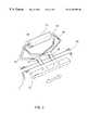
- FIG. 2is a close-up view of the distal section of the catheter system comprising a rollable electrode means at the distal end having linear lesion capabilities.
- FIG. 3is a perspective view of the electrode element, including a rollable electrode at the distal section of a catheter system.
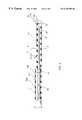
- FIG. 4is a cross-sectional view of the distal section of a catheter system comprising a rollable electrode and its moving wire configuration.
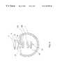
- FIG. 5is a transverse view of the attachment setup of the rollable electrode on a moving wire inside the open groove of a catheter shaft.
- FIG. 6is a simulated view of the catheter of the present invention in contact with the tissues.
- FIG. 1shows an overall view of the catheter system having a rollable electrode at its distal tip section.
- a catheter system constructed in accordance with the principles of the present inventioncomprises: a catheter shaft 1 having a distal tip section 2 , a distal end 3 , a proximal end 4 , and at least one lumen extending therebetween.
- the catheter systemcomprises a fluid infusion mechanism 5 close to the proximal end 4 of the catheter shaft 1 .
- a control valve 6is provided to the fluid infusion mechanism 5 which is externally connected to a fluid supply source having a pump and means (not shown) for controlling the flow rate of fluid through the lumen to optimize the cooling of the electrode of the catheter.
- a handle 7is attached to the proximal end 4 of the said catheter shaft 1 .
- the handlehas one optional steering mechanism 9 .
- the steering mechanism 9is to deflect the tip section 2 of the catheter shaft 1 for catheter maneuvering and positioning. By pushing forward the front plunger 10 of the handle 7 , the distal tip section 2 of the catheter shaft deflects to one direction. By pulling back the front plunger 10 , the tip section returns to its neutral position.
- the steering mechanism 9 at the handle 7comprises means for providing a plurality of deflectable curves on the distal tip section 2 of the catheter shaft.
- the mechanism of an ablation catheter having multiple flexible curvesis described by a patent application Ser. No. 08/763,614, filed Dec. 11, 1996, now U.S. Pat. No. 5,782,828.
- the catheter systemhas an electrode rolling controller 11 on the handle 7 , wherein a moving wire 12 (shown in FIG. 3) is secured to the electrode rolling controller and is capable of moving forward and backward as controlled by the electrode rolling controller 11 .
- a rollable electrode 13is disposed and secured on the moving wire 12 so that the rollable electrode is controlled back and forth by the said electrode-rolling controller 11 .
- the rolling range of the rollable electrode 13 at the distal tip section 2is restricted by a first stopper 14 and a second stopper 15 .
- FIG. 2shows a close-up view of the distal section 2 of the catheter system comprising a rollable electrode 13 at the distal portion.
- the rollable electrode 13 and its support 16sits on a moving wire 12 .
- the traveling action of the rollable electrode 13 within the open groove 17is controlled by the electrode rolling controller 11 while the traveling range is restricted by the first stopper 14 and the second stopper 15 .
- FIG. 3shows a perspective view of the electrode element, including a rollable electrode 13 at the distal section 2 of a catheter system.
- the electrode elementis consisted of a rollable electrode 13 , a pair of electrode shafts 18 , a plurality of supports 16 , and an anchoring leg means 19 .
- the rollable electrodecan be selected from a group consisting of a cylindrical roller, a ball-type roller, an oval-type roller, a porous roller, a roller with studded surface and the like.
- the electrode elementis preferably made of conductive material, while the surfaces of the shafts 18 , supports 16 , the anchoring leg means 19 , and the moving wire 12 are preferably covered with an insulating material or insulated.
- the anchoring leg means 19is secured to the moving wire 12 through an open slit 20 of the open groove 17 , wherein the moving wire 12 is preferred to be made of a flat wire.
- the moving wire 12is pushed forward by the electrode rolling controller 11 , the rollable electrode 13 moves forward, too. The rollable electrode 13 tends to roll when it contacts the tissues.
- a fluid conveying lumen 21is associated with the elongate catheter shaft 1 , and is preferably disposed within the catheter shaft along the longitudinal axis thereof.
- the fluid conveying lumenis adapted to communicate with a fluid supply source (not shown) to convey fluid from the source and through the said lumen to be discharged out of the tip section 2 at the slit opening 20 .
- the fluid flow rate from the fluid infusion mechanism 5may be between approximately 5 ml/min to 20 ml/min.
- the tip section 2 of the catheter shaft 1comprises at least one other electrode 22 .
- the stopper 14 or 15may be considered as one of the at least one other electrode 22 .
- the electrodesare formed of conducting materials selected from the group of platinum, iridium, gold, silver, stainless steel, and Nitinol.
- FIG. 4shows a cross-sectional view of the distal section 2 of a catheter system comprising a rollable electrode 13 and its moving wire configuration 12 .
- the electrode rolling controller 11 and its associated moving wire 12constitute the main mechanism of the electrode rolling capabilities.
- the moving wire 12is a close loop wiring and comprises a upper wire 12 A and a lower wire 12 B, which are supported by a first pulley 23 near the distal portion of the catheter shaft 1 and a second pulley 24 near the distal end of the catheter shaft 1 .
- the electrode elementincluding a rollable electrode 13 , a pair of electrode shafts 18 , a plurality of supports 16 , and anchoring leg means 19 are secured on the moving wire 12 .
- the at least one electrode 22has an insulated conducting wire (not shown) secured to the electrode, which passes through the lumen of the catheter shaft 1 and is soldered to a contact pin of the connector 8 at the proximal end of the handle 7 .
- the conducting wire from the end of the connectoris externally connected to an EKG monitor for diagnosis or to a RF generator during an electrophysiology ablation procedure. Therefrom, the RF energy is transmitted through the conducting wire to the electrode and the RF energy is delivered to the target tissue.
- a temperature sensor 25is constructed at the proximity of the electrode 13 or 22 to measure the tissue contact temperature when RF energy is delivered.
- the temperature sensing wire (not shown) from the thermocouple or thermisteris connected to one of the contact pins (not shown) of the connector 8 and externally connected to a transducer and to a temperature controller.
- the temperature readingis thereafter relayed to a close-loop control mechanism to adjust the RF energy output.
- the RF energy deliveredis thus controlled by the temperature sensor reading or by a pre-programmed control algorithm.
- the catheter of this inventionis meant to provide fluid communication and commensurate flow of fluid originating inside the tip section of the catheter shaft to the electrode exterior surface, which directs the fluid flow from inside the catheter shaft over the exterior surface of the electrode to provide a fluid protective layer surrounding the electrode to minimize temperature elevation of the electrode with biological tissues.
- This fluid protective layer surrounding the rollable electrodeis better maintained when the electrode is freely rollable.
- the ablation catheter systemfurther comprises a steering mechanism 9 at the handle 7 for controlling the deflection of the said distal tip section 2 having a rollable electrode 13 .
- a steering mechanism 9at the handle 7 for controlling the deflection of the said distal tip section 2 having a rollable electrode 13 .
- a rotating ring or a push-pull plunger 8is employed in the steering mechanism.
- a flat wire 26is disposed at the distal tip section 2 .
- a pulling wire 27is used to control the degree of pulling on the flat wire 26 , thus effects the deflection of the catheter shaft 1 at the distal portion 2 .
- FIG. 5shows a transverse view of the attachment setup of the rollable electrode on a moving wire 12 inside the open groove 17 of a catheter shaft 1 .
- the electrode elementcomprises a rollable electrode 13 , electrode shafts 18 , supports 16 , and anchoring leg means 19 .
- the anchoring leg means 19is firmly secured on the upper moving wire 12 A.
- the upper moving wire 12 A and the returning lower moving wire 12 Bconstitute a close-loop wiring, which is controlled by the electrode rolling controller 11 for moving the said wire forward or backward.
- FIG. 6shows a simulated view of the catheter of the present invention in contact with the tissues 28 .
- the rollable electrode 13moves from the first stopper end 14 to the second stopper end 15 along the open groove 17 of the distal end section 2 of the catheter shaft 1 by manipulating the electrode rolling controller 11 at the handle 7 .
- the catheter itselfis stationary with respect to the location of the tissues 28 .
- the RF energyis simultaneously delivered to the tissue to create a “true” linear lesion for tissue ablation.
Landscapes
- Health & Medical Sciences (AREA)
- Life Sciences & Earth Sciences (AREA)
- Surgery (AREA)
- Engineering & Computer Science (AREA)
- Plasma & Fusion (AREA)
- Medical Informatics (AREA)
- Otolaryngology (AREA)
- Physics & Mathematics (AREA)
- Cardiology (AREA)
- Biomedical Technology (AREA)
- Heart & Thoracic Surgery (AREA)
- Nuclear Medicine, Radiotherapy & Molecular Imaging (AREA)
- Molecular Biology (AREA)
- Animal Behavior & Ethology (AREA)
- General Health & Medical Sciences (AREA)
- Public Health (AREA)
- Veterinary Medicine (AREA)
- Surgical Instruments (AREA)
Abstract
Description
Claims (20)
Priority Applications (3)
| Application Number | Priority Date | Filing Date | Title |
|---|---|---|---|
| US09/085,543US6238390B1 (en) | 1998-05-27 | 1998-05-27 | Ablation catheter system having linear lesion capabilities |
| US09/351,080US6241727B1 (en) | 1998-05-27 | 1999-07-09 | Ablation catheter system having circular lesion capabilities |
| US09/874,632US20010044625A1 (en) | 1998-05-27 | 2001-06-04 | Catheter for circular tissue ablation and methods thereof |
Applications Claiming Priority (1)
| Application Number | Priority Date | Filing Date | Title |
|---|---|---|---|
| US09/085,543US6238390B1 (en) | 1998-05-27 | 1998-05-27 | Ablation catheter system having linear lesion capabilities |
Related Child Applications (1)
| Application Number | Title | Priority Date | Filing Date |
|---|---|---|---|
| US09/351,080Continuation-In-PartUS6241727B1 (en) | 1998-05-27 | 1999-07-09 | Ablation catheter system having circular lesion capabilities |
Publications (1)
| Publication Number | Publication Date |
|---|---|
| US6238390B1true US6238390B1 (en) | 2001-05-29 |
Family
ID=22192311
Family Applications (1)
| Application Number | Title | Priority Date | Filing Date |
|---|---|---|---|
| US09/085,543Expired - LifetimeUS6238390B1 (en) | 1998-05-27 | 1998-05-27 | Ablation catheter system having linear lesion capabilities |
Country Status (1)
| Country | Link |
|---|---|
| US (1) | US6238390B1 (en) |
Cited By (65)
| Publication number | Priority date | Publication date | Assignee | Title |
|---|---|---|---|---|
| WO2002080792A1 (en)* | 2001-04-04 | 2002-10-17 | Moshe Ein-Gal | Electrosurgical apparatus |
| US20030050557A1 (en)* | 1998-11-04 | 2003-03-13 | Susil Robert C. | Systems and methods for magnetic-resonance-guided interventional procedures |
| US20030199755A1 (en)* | 1998-11-04 | 2003-10-23 | Johns Hopkins University School Of Medicine | System and method for magnetic-resonance-guided electrophysiologic and ablation procedures |
| US20030208252A1 (en)* | 2001-05-14 | 2003-11-06 | O' Boyle Gary S. | Mri ablation catheter |
| US6666864B2 (en) | 2001-06-29 | 2003-12-23 | Scimed Life Systems, Inc. | Electrophysiological probes having selective element actuation and variable lesion length capability |
| US20040127933A1 (en)* | 2002-12-30 | 2004-07-01 | Jackson Demond | Embolic protection device |
| US20040254571A1 (en)* | 2003-01-31 | 2004-12-16 | Kobi Iki | Cartilage treatment probe |
| US20050033137A1 (en)* | 2002-10-25 | 2005-02-10 | The Regents Of The University Of Michigan | Ablation catheters and methods for their use |
| US20050238619A1 (en)* | 2004-03-18 | 2005-10-27 | Riley Lee B | Method for the delivery of sustained release agents |
| US20050245925A1 (en)* | 2003-01-31 | 2005-11-03 | Kobi Iki | Cartilage treatment probe |
| US20050251132A1 (en)* | 2002-10-25 | 2005-11-10 | Regents Of The University Of Michigan | Ablation catheters |
| US20060025761A1 (en)* | 2004-07-29 | 2006-02-02 | Riley Lee B | Linear-array radio frequency resections |
| US20060111701A1 (en)* | 2004-11-24 | 2006-05-25 | Ablation Frontiers, Inc. | Atrial ablation catheter adapted for treatment of septal wall arrhythmogenic foci and method of use |
| US20060111700A1 (en)* | 2004-11-24 | 2006-05-25 | Ablation Frontiers, Inc. | Atrial ablation catheter and method of use |
| US20060241704A1 (en)* | 2005-04-25 | 2006-10-26 | Allan Shuros | Method and apparatus for pacing during revascularization |
| US20090318984A1 (en)* | 2008-06-19 | 2009-12-24 | Mokelke Eric A | External pacemaker with automatic cardioprotective pacing protocol |
| US20090318991A1 (en)* | 2008-06-19 | 2009-12-24 | Tomaschko Daniel K | Pacing catheter for access to multiple vessels |
| US20090318989A1 (en)* | 2008-06-19 | 2009-12-24 | Tomaschko Daniel K | Pacing catheter with stent electrode |
| US20090318994A1 (en)* | 2008-06-19 | 2009-12-24 | Tracee Eidenschink | Transvascular balloon catheter with pacing electrodes on shaft |
| US20090318993A1 (en)* | 2008-06-19 | 2009-12-24 | Tracee Eidenschink | Pacemaker integrated with vascular intervention catheter |
| US20090318749A1 (en)* | 2008-06-19 | 2009-12-24 | Craig Stolen | Method and apparatus for pacing and intermittent ischemia |
| US20100056858A1 (en)* | 2008-09-02 | 2010-03-04 | Mokelke Eric A | Pacing system for use during cardiac catheterization or surgery |
| US20100130913A1 (en)* | 2006-08-31 | 2010-05-27 | Tamara Colette Baynham | Integrated catheter and pulse generator systems and methods |
| US20100160997A1 (en)* | 2001-04-13 | 2010-06-24 | Greatbatch Ltd. | Tuned energy balanced system for minimizing heating and/or to provide emi protection of implanted leads in a high power electromagnetic field environment |
| US20100168821A1 (en)* | 2001-04-13 | 2010-07-01 | Greatbatch Ltd. | Switched diverter circuits for minimizing heating of an implanted lead in a high power electromagnetic field environment |
| US20100191236A1 (en)* | 2001-04-13 | 2010-07-29 | Greatbatch Ltd. | Switched diverter circuits for minimizing heating of an implanted lead and/or providing emi protection in a high power electromagnetic field environment |
| US20100208397A1 (en)* | 2008-12-17 | 2010-08-19 | Greatbatch Ltd. | Switched safety protection circuit for an aimd system during exposure to high power electromagnetic fields |
| US7850685B2 (en) | 2005-06-20 | 2010-12-14 | Medtronic Ablation Frontiers Llc | Ablation catheter |
| USRE42856E1 (en) | 2002-05-29 | 2011-10-18 | MRI Interventions, Inc. | Magnetic resonance probes |
| US8095224B2 (en) | 2009-03-19 | 2012-01-10 | Greatbatch Ltd. | EMI shielded conduit assembly for an active implantable medical device |
| US8187266B2 (en) | 2006-09-29 | 2012-05-29 | Quantumcor, Inc. | Surgical probe and methods for targeted treatment of heart structures |
| US8219208B2 (en) | 2001-04-13 | 2012-07-10 | Greatbatch Ltd. | Frequency selective passive component networks for active implantable medical devices utilizing an energy dissipating surface |
| US8244352B2 (en) | 2008-06-19 | 2012-08-14 | Cardiac Pacemakers, Inc. | Pacing catheter releasing conductive liquid |
| US8275466B2 (en) | 2006-06-08 | 2012-09-25 | Greatbatch Ltd. | Band stop filter employing a capacitor and an inductor tank circuit to enhance MRI compatibility of active medical devices |
| US8328798B2 (en) | 1999-10-02 | 2012-12-11 | Quantumcor, Inc | Method for treating and repairing mitral valve annulus |
| US8369930B2 (en) | 2009-06-16 | 2013-02-05 | MRI Interventions, Inc. | MRI-guided devices and MRI-guided interventional systems that can track and generate dynamic visualizations of the devices in near real time |
| US8486063B2 (en) | 2004-10-14 | 2013-07-16 | Medtronic Ablation Frontiers Llc | Ablation catheter |
| US8600519B2 (en) | 2001-04-13 | 2013-12-03 | Greatbatch Ltd. | Transient voltage/current protection system for electronic circuits associated with implanted leads |
| US8617152B2 (en) | 2004-11-15 | 2013-12-31 | Medtronic Ablation Frontiers Llc | Ablation system with feedback |
| US8641704B2 (en) | 2007-05-11 | 2014-02-04 | Medtronic Ablation Frontiers Llc | Ablation therapy system and method for treating continuous atrial fibrillation |
| US8657814B2 (en) | 2005-08-22 | 2014-02-25 | Medtronic Ablation Frontiers Llc | User interface for tissue ablation system |
| US8834461B2 (en) | 2005-07-11 | 2014-09-16 | Medtronic Ablation Frontiers Llc | Low power tissue ablation system |
| US8903505B2 (en) | 2006-06-08 | 2014-12-02 | Greatbatch Ltd. | Implantable lead bandstop filter employing an inductive coil with parasitic capacitance to enhance MRI compatibility of active medical devices |
| US20140371742A1 (en)* | 2013-06-18 | 2014-12-18 | Vascomed Gmbh | Anatomical Ablation System for the Purpose of Pulmonary Vein Isolation |
| US8974445B2 (en) | 2009-01-09 | 2015-03-10 | Recor Medical, Inc. | Methods and apparatus for treatment of cardiac valve insufficiency |
| US8977355B2 (en) | 2001-04-13 | 2015-03-10 | Greatbatch Ltd. | EMI filter employing a capacitor and an inductor tank circuit having optimum component values |
| US9037235B2 (en) | 2008-06-19 | 2015-05-19 | Cardiac Pacemakers, Inc. | Pacing catheter with expandable distal end |
| US9108066B2 (en) | 2008-03-20 | 2015-08-18 | Greatbatch Ltd. | Low impedance oxide resistant grounded capacitor for an AIMD |
| US9242090B2 (en) | 2001-04-13 | 2016-01-26 | MRI Interventions Inc. | MRI compatible medical leads |
| US9248283B2 (en) | 2001-04-13 | 2016-02-02 | Greatbatch Ltd. | Band stop filter comprising an inductive component disposed in a lead wire in series with an electrode |
| US9259290B2 (en) | 2009-06-08 | 2016-02-16 | MRI Interventions, Inc. | MRI-guided surgical systems with proximity alerts |
| US9295828B2 (en) | 2001-04-13 | 2016-03-29 | Greatbatch Ltd. | Self-resonant inductor wound portion of an implantable lead for enhanced MRI compatibility of active implantable medical devices |
| US9427596B2 (en) | 2013-01-16 | 2016-08-30 | Greatbatch Ltd. | Low impedance oxide resistant grounded capacitor for an AIMD |
| US9700372B2 (en) | 2002-07-01 | 2017-07-11 | Recor Medical, Inc. | Intraluminal methods of ablating nerve tissue |
| USRE46699E1 (en) | 2013-01-16 | 2018-02-06 | Greatbatch Ltd. | Low impedance oxide resistant grounded capacitor for an AIMD |
| US9931514B2 (en) | 2013-06-30 | 2018-04-03 | Greatbatch Ltd. | Low impedance oxide resistant grounded capacitor for an AIMD |
| US10080889B2 (en) | 2009-03-19 | 2018-09-25 | Greatbatch Ltd. | Low inductance and low resistance hermetically sealed filtered feedthrough for an AIMD |
| US10350421B2 (en) | 2013-06-30 | 2019-07-16 | Greatbatch Ltd. | Metallurgically bonded gold pocket pad for grounding an EMI filter to a hermetic terminal for an active implantable medical device |
| US10559409B2 (en) | 2017-01-06 | 2020-02-11 | Greatbatch Ltd. | Process for manufacturing a leadless feedthrough for an active implantable medical device |
| US10561837B2 (en) | 2011-03-01 | 2020-02-18 | Greatbatch Ltd. | Low equivalent series resistance RF filter for an active implantable medical device utilizing a ceramic reinforced metal composite filled via |
| US10589107B2 (en) | 2016-11-08 | 2020-03-17 | Greatbatch Ltd. | Circuit board mounted filtered feedthrough assembly having a composite conductive lead for an AIMD |
| US10905888B2 (en) | 2018-03-22 | 2021-02-02 | Greatbatch Ltd. | Electrical connection for an AIMD EMI filter utilizing an anisotropic conductive layer |
| US10912945B2 (en) | 2018-03-22 | 2021-02-09 | Greatbatch Ltd. | Hermetic terminal for an active implantable medical device having a feedthrough capacitor partially overhanging a ferrule for high effective capacitance area |
| US11198014B2 (en) | 2011-03-01 | 2021-12-14 | Greatbatch Ltd. | Hermetically sealed filtered feedthrough assembly having a capacitor with an oxide resistant electrical connection to an active implantable medical device housing |
| CN117694998A (en)* | 2024-02-05 | 2024-03-15 | 杭州科嘉生物技术有限公司 | Circulation cooling type ablation device |
Citations (6)
| Publication number | Priority date | Publication date | Assignee | Title |
|---|---|---|---|---|
| US5354296A (en)* | 1993-03-24 | 1994-10-11 | Symbiosis Corporation | Electrocautery probe with variable morphology electrode |
| US5395363A (en)* | 1993-06-29 | 1995-03-07 | Utah Medical Products | Diathermy coagulation and ablation apparatus and method |
| US5634924A (en)* | 1995-08-28 | 1997-06-03 | Symbiosis Corporation | Bipolar roller electrodes and electrocautery probes for use with a resectoscope |
| US5766215A (en)* | 1995-09-27 | 1998-06-16 | Endocare, Inc. | Electrosurgical loop providing enhanced tissue coagulation |
| US5843019A (en)* | 1992-01-07 | 1998-12-01 | Arthrocare Corporation | Shaped electrodes and methods for electrosurgical cutting and ablation |
| US5893884A (en)* | 1997-05-19 | 1999-04-13 | Irvine Biomedical, Inc. | Catheter system having rollable electrode means |
- 1998
- 1998-05-27USUS09/085,543patent/US6238390B1/ennot_activeExpired - Lifetime
Patent Citations (6)
| Publication number | Priority date | Publication date | Assignee | Title |
|---|---|---|---|---|
| US5843019A (en)* | 1992-01-07 | 1998-12-01 | Arthrocare Corporation | Shaped electrodes and methods for electrosurgical cutting and ablation |
| US5354296A (en)* | 1993-03-24 | 1994-10-11 | Symbiosis Corporation | Electrocautery probe with variable morphology electrode |
| US5395363A (en)* | 1993-06-29 | 1995-03-07 | Utah Medical Products | Diathermy coagulation and ablation apparatus and method |
| US5634924A (en)* | 1995-08-28 | 1997-06-03 | Symbiosis Corporation | Bipolar roller electrodes and electrocautery probes for use with a resectoscope |
| US5766215A (en)* | 1995-09-27 | 1998-06-16 | Endocare, Inc. | Electrosurgical loop providing enhanced tissue coagulation |
| US5893884A (en)* | 1997-05-19 | 1999-04-13 | Irvine Biomedical, Inc. | Catheter system having rollable electrode means |
Cited By (126)
| Publication number | Priority date | Publication date | Assignee | Title |
|---|---|---|---|---|
| US20040167392A1 (en)* | 1998-11-04 | 2004-08-26 | Halperin Henry R. | Brain therapy |
| US20030050557A1 (en)* | 1998-11-04 | 2003-03-13 | Susil Robert C. | Systems and methods for magnetic-resonance-guided interventional procedures |
| US20030199755A1 (en)* | 1998-11-04 | 2003-10-23 | Johns Hopkins University School Of Medicine | System and method for magnetic-resonance-guided electrophysiologic and ablation procedures |
| US9301705B2 (en) | 1998-11-04 | 2016-04-05 | Johns Hopkins University School Of Medicine | System and method for magnetic-resonance-guided electrophysiologic and ablation procedures |
| US7822460B2 (en) | 1998-11-04 | 2010-10-26 | Surgi-Vision, Inc. | MRI-guided therapy methods and related systems |
| US7844319B2 (en) | 1998-11-04 | 2010-11-30 | Susil Robert C | Systems and methods for magnetic-resonance-guided interventional procedures |
| US20060100506A1 (en)* | 1998-11-04 | 2006-05-11 | Johns Hopkins University School Of Medicine | System and method for magnetic-resonance-guided electrophysiologic and ablation procedures |
| US7412276B2 (en) | 1998-11-04 | 2008-08-12 | Johns Hopkins University School Of Medicine | Brain therapy |
| US20080058635A1 (en)* | 1998-11-04 | 2008-03-06 | Johns Hopkins University School Of Medicine | Mri-guided therapy methods and related systems |
| US7155271B2 (en) | 1998-11-04 | 2006-12-26 | Johns Hopkins University School Of Medicine | System and method for magnetic-resonance-guided electrophysiologic and ablation procedures |
| US8099151B2 (en) | 1998-11-04 | 2012-01-17 | Johns Hopkins University School Of Medicine | System and method for magnetic-resonance-guided electrophysiologic and ablation procedures |
| US8328798B2 (en) | 1999-10-02 | 2012-12-11 | Quantumcor, Inc | Method for treating and repairing mitral valve annulus |
| WO2002080792A1 (en)* | 2001-04-04 | 2002-10-17 | Moshe Ein-Gal | Electrosurgical apparatus |
| US8977355B2 (en) | 2001-04-13 | 2015-03-10 | Greatbatch Ltd. | EMI filter employing a capacitor and an inductor tank circuit having optimum component values |
| US8457760B2 (en) | 2001-04-13 | 2013-06-04 | Greatbatch Ltd. | Switched diverter circuits for minimizing heating of an implanted lead and/or providing EMI protection in a high power electromagnetic field environment |
| US8989870B2 (en) | 2001-04-13 | 2015-03-24 | Greatbatch Ltd. | Tuned energy balanced system for minimizing heating and/or to provide EMI protection of implanted leads in a high power electromagnetic field environment |
| US20100168821A1 (en)* | 2001-04-13 | 2010-07-01 | Greatbatch Ltd. | Switched diverter circuits for minimizing heating of an implanted lead in a high power electromagnetic field environment |
| US8600519B2 (en) | 2001-04-13 | 2013-12-03 | Greatbatch Ltd. | Transient voltage/current protection system for electronic circuits associated with implanted leads |
| US8751013B2 (en) | 2001-04-13 | 2014-06-10 | Greatbatch Ltd. | Switched diverter circuits for minimizing heating of an implanted lead and/or providing EMI protection in a high power electromagnetic field environment |
| US8219208B2 (en) | 2001-04-13 | 2012-07-10 | Greatbatch Ltd. | Frequency selective passive component networks for active implantable medical devices utilizing an energy dissipating surface |
| US8855785B1 (en) | 2001-04-13 | 2014-10-07 | Greatbatch Ltd. | Circuits for minimizing heating of an implanted lead and/or providing EMI protection in a high power electromagnetic field environment |
| US8509913B2 (en) | 2001-04-13 | 2013-08-13 | Greatbatch Ltd. | Switched diverter circuits for minimizing heating of an implanted lead and/or providing EMI protection in a high power electromagnetic field environment |
| US9242090B2 (en) | 2001-04-13 | 2016-01-26 | MRI Interventions Inc. | MRI compatible medical leads |
| US9248283B2 (en) | 2001-04-13 | 2016-02-02 | Greatbatch Ltd. | Band stop filter comprising an inductive component disposed in a lead wire in series with an electrode |
| US20100160997A1 (en)* | 2001-04-13 | 2010-06-24 | Greatbatch Ltd. | Tuned energy balanced system for minimizing heating and/or to provide emi protection of implanted leads in a high power electromagnetic field environment |
| US9295828B2 (en) | 2001-04-13 | 2016-03-29 | Greatbatch Ltd. | Self-resonant inductor wound portion of an implantable lead for enhanced MRI compatibility of active implantable medical devices |
| US20100191236A1 (en)* | 2001-04-13 | 2010-07-29 | Greatbatch Ltd. | Switched diverter circuits for minimizing heating of an implanted lead and/or providing emi protection in a high power electromagnetic field environment |
| US20030208252A1 (en)* | 2001-05-14 | 2003-11-06 | O' Boyle Gary S. | Mri ablation catheter |
| US6666864B2 (en) | 2001-06-29 | 2003-12-23 | Scimed Life Systems, Inc. | Electrophysiological probes having selective element actuation and variable lesion length capability |
| USRE44736E1 (en) | 2002-05-29 | 2014-01-28 | MRI Interventions, Inc. | Magnetic resonance probes |
| USRE42856E1 (en) | 2002-05-29 | 2011-10-18 | MRI Interventions, Inc. | Magnetic resonance probes |
| US9700372B2 (en) | 2002-07-01 | 2017-07-11 | Recor Medical, Inc. | Intraluminal methods of ablating nerve tissue |
| US9707034B2 (en) | 2002-07-01 | 2017-07-18 | Recor Medical, Inc. | Intraluminal method and apparatus for ablating nerve tissue |
| US7993333B2 (en) | 2002-10-25 | 2011-08-09 | The Regents Of The University Of Michigan | Ablation catheters |
| US20050033137A1 (en)* | 2002-10-25 | 2005-02-10 | The Regents Of The University Of Michigan | Ablation catheters and methods for their use |
| US20050251132A1 (en)* | 2002-10-25 | 2005-11-10 | Regents Of The University Of Michigan | Ablation catheters |
| US20070106293A1 (en)* | 2002-10-25 | 2007-05-10 | Hakan Oral | Ablation catheters |
| US7857808B2 (en) | 2002-10-25 | 2010-12-28 | The Regents Of The University Of Michigan | Ablation catheters |
| US20080161803A1 (en)* | 2002-10-25 | 2008-07-03 | The Regents Of The University Of Michigan | Ablation Catheters And Methods For Their Use |
| US8123779B2 (en) | 2002-12-30 | 2012-02-28 | Boston Scientific Scimed, Inc. | Embolic protection device |
| US7625389B2 (en)* | 2002-12-30 | 2009-12-01 | Boston Scientific Scimed, Inc. | Embolic protection device |
| US20040127933A1 (en)* | 2002-12-30 | 2004-07-01 | Jackson Demond | Embolic protection device |
| US8377058B2 (en) | 2003-01-31 | 2013-02-19 | Smith & Nephew, Inc. | Cartilage treatment probe |
| US7951142B2 (en)* | 2003-01-31 | 2011-05-31 | Smith & Nephew, Inc. | Cartilage treatment probe |
| US20040254571A1 (en)* | 2003-01-31 | 2004-12-16 | Kobi Iki | Cartilage treatment probe |
| US8500734B2 (en) | 2003-01-31 | 2013-08-06 | Smith & Nephew, Inc. | Cartilage treatment probe |
| US8066700B2 (en)* | 2003-01-31 | 2011-11-29 | Smith & Nephew, Inc. | Cartilage treatment probe |
| US20050245925A1 (en)* | 2003-01-31 | 2005-11-03 | Kobi Iki | Cartilage treatment probe |
| US20050238619A1 (en)* | 2004-03-18 | 2005-10-27 | Riley Lee B | Method for the delivery of sustained release agents |
| US20060025761A1 (en)* | 2004-07-29 | 2006-02-02 | Riley Lee B | Linear-array radio frequency resections |
| US9642675B2 (en) | 2004-10-14 | 2017-05-09 | Medtronic Ablation Frontiers Llc | Ablation catheter |
| US8486063B2 (en) | 2004-10-14 | 2013-07-16 | Medtronic Ablation Frontiers Llc | Ablation catheter |
| US8617152B2 (en) | 2004-11-15 | 2013-12-31 | Medtronic Ablation Frontiers Llc | Ablation system with feedback |
| US20060111701A1 (en)* | 2004-11-24 | 2006-05-25 | Ablation Frontiers, Inc. | Atrial ablation catheter adapted for treatment of septal wall arrhythmogenic foci and method of use |
| US8273084B2 (en) | 2004-11-24 | 2012-09-25 | Medtronic Ablation Frontiers Llc | Atrial ablation catheter and method of use |
| US9005194B2 (en) | 2004-11-24 | 2015-04-14 | Medtronic Ablation Frontiers Llc | Atrial ablation catheter adapted for treatment of septal wall arrhythmogenic foci and method of use |
| US7429261B2 (en) | 2004-11-24 | 2008-09-30 | Ablation Frontiers, Inc. | Atrial ablation catheter and method of use |
| US20060111700A1 (en)* | 2004-11-24 | 2006-05-25 | Ablation Frontiers, Inc. | Atrial ablation catheter and method of use |
| US7468062B2 (en) | 2004-11-24 | 2008-12-23 | Ablation Frontiers, Inc. | Atrial ablation catheter adapted for treatment of septal wall arrhythmogenic foci and method of use |
| US8452400B2 (en) | 2005-04-25 | 2013-05-28 | Cardiac Pacemakers, Inc. | Method and apparatus for pacing during revascularization |
| US7962208B2 (en) | 2005-04-25 | 2011-06-14 | Cardiac Pacemakers, Inc. | Method and apparatus for pacing during revascularization |
| US10549101B2 (en) | 2005-04-25 | 2020-02-04 | Cardiac Pacemakers, Inc. | Method and apparatus for pacing during revascularization |
| US20060241704A1 (en)* | 2005-04-25 | 2006-10-26 | Allan Shuros | Method and apparatus for pacing during revascularization |
| US9649495B2 (en) | 2005-04-25 | 2017-05-16 | Cardiac Pacemakers, Inc. | Method and apparatus for pacing during revascularization |
| US9415225B2 (en) | 2005-04-25 | 2016-08-16 | Cardiac Pacemakers, Inc. | Method and apparatus for pacing during revascularization |
| US20110230928A1 (en)* | 2005-04-25 | 2011-09-22 | Allan Shuros | Method and apparatus for pacing during revascularization |
| US7850685B2 (en) | 2005-06-20 | 2010-12-14 | Medtronic Ablation Frontiers Llc | Ablation catheter |
| US8337492B2 (en) | 2005-06-20 | 2012-12-25 | Medtronic Ablation Frontiers Llc | Ablation catheter |
| US8979841B2 (en) | 2005-06-20 | 2015-03-17 | Medtronic Ablation Frontiers Llc | Ablation catheter |
| US8771267B2 (en) | 2005-06-20 | 2014-07-08 | Medtronic Ablation Frontiers Llc | Ablation catheter |
| US9468495B2 (en) | 2005-06-20 | 2016-10-18 | Medtronic Ablation Frontiers Llc | Ablation catheter |
| US8834461B2 (en) | 2005-07-11 | 2014-09-16 | Medtronic Ablation Frontiers Llc | Low power tissue ablation system |
| US9566113B2 (en) | 2005-07-11 | 2017-02-14 | Medtronic Ablation Frontiers Llc | Low power tissue ablation system |
| US8657814B2 (en) | 2005-08-22 | 2014-02-25 | Medtronic Ablation Frontiers Llc | User interface for tissue ablation system |
| US9119968B2 (en) | 2006-06-08 | 2015-09-01 | Greatbatch Ltd. | Band stop filter employing a capacitor and an inductor tank circuit to enhance MRI compatibility of active medical devices |
| US8275466B2 (en) | 2006-06-08 | 2012-09-25 | Greatbatch Ltd. | Band stop filter employing a capacitor and an inductor tank circuit to enhance MRI compatibility of active medical devices |
| US8903505B2 (en) | 2006-06-08 | 2014-12-02 | Greatbatch Ltd. | Implantable lead bandstop filter employing an inductive coil with parasitic capacitance to enhance MRI compatibility of active medical devices |
| US9008799B2 (en) | 2006-06-08 | 2015-04-14 | Greatbatch Ltd. | EMI filter employing a self-resonant inductor bandstop filter having optimum inductance and capacitance values |
| US20100130913A1 (en)* | 2006-08-31 | 2010-05-27 | Tamara Colette Baynham | Integrated catheter and pulse generator systems and methods |
| US8187266B2 (en) | 2006-09-29 | 2012-05-29 | Quantumcor, Inc. | Surgical probe and methods for targeted treatment of heart structures |
| US8641704B2 (en) | 2007-05-11 | 2014-02-04 | Medtronic Ablation Frontiers Llc | Ablation therapy system and method for treating continuous atrial fibrillation |
| US8771269B2 (en) | 2007-05-11 | 2014-07-08 | Medtronic Ablation Frontiers Llc | RF energy delivery system and method |
| US10219857B2 (en) | 2007-05-11 | 2019-03-05 | Medtronic Ablation Frontiers Llc | RF energy delivery system |
| US9108066B2 (en) | 2008-03-20 | 2015-08-18 | Greatbatch Ltd. | Low impedance oxide resistant grounded capacitor for an AIMD |
| US20090318749A1 (en)* | 2008-06-19 | 2009-12-24 | Craig Stolen | Method and apparatus for pacing and intermittent ischemia |
| US20090318984A1 (en)* | 2008-06-19 | 2009-12-24 | Mokelke Eric A | External pacemaker with automatic cardioprotective pacing protocol |
| US8457738B2 (en) | 2008-06-19 | 2013-06-04 | Cardiac Pacemakers, Inc. | Pacing catheter for access to multiple vessels |
| US8244352B2 (en) | 2008-06-19 | 2012-08-14 | Cardiac Pacemakers, Inc. | Pacing catheter releasing conductive liquid |
| US20090318991A1 (en)* | 2008-06-19 | 2009-12-24 | Tomaschko Daniel K | Pacing catheter for access to multiple vessels |
| US9037235B2 (en) | 2008-06-19 | 2015-05-19 | Cardiac Pacemakers, Inc. | Pacing catheter with expandable distal end |
| US8639357B2 (en) | 2008-06-19 | 2014-01-28 | Cardiac Pacemakers, Inc. | Pacing catheter with stent electrode |
| US9409012B2 (en) | 2008-06-19 | 2016-08-09 | Cardiac Pacemakers, Inc. | Pacemaker integrated with vascular intervention catheter |
| US20090318989A1 (en)* | 2008-06-19 | 2009-12-24 | Tomaschko Daniel K | Pacing catheter with stent electrode |
| US20090318993A1 (en)* | 2008-06-19 | 2009-12-24 | Tracee Eidenschink | Pacemaker integrated with vascular intervention catheter |
| US20090318994A1 (en)* | 2008-06-19 | 2009-12-24 | Tracee Eidenschink | Transvascular balloon catheter with pacing electrodes on shaft |
| US20100056858A1 (en)* | 2008-09-02 | 2010-03-04 | Mokelke Eric A | Pacing system for use during cardiac catheterization or surgery |
| US8447414B2 (en) | 2008-12-17 | 2013-05-21 | Greatbatch Ltd. | Switched safety protection circuit for an AIMD system during exposure to high power electromagnetic fields |
| US20100208397A1 (en)* | 2008-12-17 | 2010-08-19 | Greatbatch Ltd. | Switched safety protection circuit for an aimd system during exposure to high power electromagnetic fields |
| US8974445B2 (en) | 2009-01-09 | 2015-03-10 | Recor Medical, Inc. | Methods and apparatus for treatment of cardiac valve insufficiency |
| US10080889B2 (en) | 2009-03-19 | 2018-09-25 | Greatbatch Ltd. | Low inductance and low resistance hermetically sealed filtered feedthrough for an AIMD |
| US8095224B2 (en) | 2009-03-19 | 2012-01-10 | Greatbatch Ltd. | EMI shielded conduit assembly for an active implantable medical device |
| US9259290B2 (en) | 2009-06-08 | 2016-02-16 | MRI Interventions, Inc. | MRI-guided surgical systems with proximity alerts |
| US9439735B2 (en) | 2009-06-08 | 2016-09-13 | MRI Interventions, Inc. | MRI-guided interventional systems that can track and generate dynamic visualizations of flexible intrabody devices in near real time |
| US8396532B2 (en) | 2009-06-16 | 2013-03-12 | MRI Interventions, Inc. | MRI-guided devices and MRI-guided interventional systems that can track and generate dynamic visualizations of the devices in near real time |
| US8825133B2 (en) | 2009-06-16 | 2014-09-02 | MRI Interventions, Inc. | MRI-guided catheters |
| US8768433B2 (en) | 2009-06-16 | 2014-07-01 | MRI Interventions, Inc. | MRI-guided devices and MRI-guided interventional systems that can track and generate dynamic visualizations of the devices in near real time |
| US8369930B2 (en) | 2009-06-16 | 2013-02-05 | MRI Interventions, Inc. | MRI-guided devices and MRI-guided interventional systems that can track and generate dynamic visualizations of the devices in near real time |
| US8886288B2 (en) | 2009-06-16 | 2014-11-11 | MRI Interventions, Inc. | MRI-guided devices and MRI-guided interventional systems that can track and generate dynamic visualizations of the devices in near real time |
| US11071858B2 (en) | 2011-03-01 | 2021-07-27 | Greatbatch Ltd. | Hermetically sealed filtered feedthrough having platinum sealed directly to the insulator in a via hole |
| US10561837B2 (en) | 2011-03-01 | 2020-02-18 | Greatbatch Ltd. | Low equivalent series resistance RF filter for an active implantable medical device utilizing a ceramic reinforced metal composite filled via |
| US10596369B2 (en) | 2011-03-01 | 2020-03-24 | Greatbatch Ltd. | Low equivalent series resistance RF filter for an active implantable medical device |
| US11198014B2 (en) | 2011-03-01 | 2021-12-14 | Greatbatch Ltd. | Hermetically sealed filtered feedthrough assembly having a capacitor with an oxide resistant electrical connection to an active implantable medical device housing |
| US9427596B2 (en) | 2013-01-16 | 2016-08-30 | Greatbatch Ltd. | Low impedance oxide resistant grounded capacitor for an AIMD |
| USRE46699E1 (en) | 2013-01-16 | 2018-02-06 | Greatbatch Ltd. | Low impedance oxide resistant grounded capacitor for an AIMD |
| US20140371742A1 (en)* | 2013-06-18 | 2014-12-18 | Vascomed Gmbh | Anatomical Ablation System for the Purpose of Pulmonary Vein Isolation |
| US9931514B2 (en) | 2013-06-30 | 2018-04-03 | Greatbatch Ltd. | Low impedance oxide resistant grounded capacitor for an AIMD |
| US10350421B2 (en) | 2013-06-30 | 2019-07-16 | Greatbatch Ltd. | Metallurgically bonded gold pocket pad for grounding an EMI filter to a hermetic terminal for an active implantable medical device |
| US10589107B2 (en) | 2016-11-08 | 2020-03-17 | Greatbatch Ltd. | Circuit board mounted filtered feedthrough assembly having a composite conductive lead for an AIMD |
| US10559409B2 (en) | 2017-01-06 | 2020-02-11 | Greatbatch Ltd. | Process for manufacturing a leadless feedthrough for an active implantable medical device |
| US10905888B2 (en) | 2018-03-22 | 2021-02-02 | Greatbatch Ltd. | Electrical connection for an AIMD EMI filter utilizing an anisotropic conductive layer |
| US10912945B2 (en) | 2018-03-22 | 2021-02-09 | Greatbatch Ltd. | Hermetic terminal for an active implantable medical device having a feedthrough capacitor partially overhanging a ferrule for high effective capacitance area |
| US11712571B2 (en) | 2018-03-22 | 2023-08-01 | Greatbatch Ltd. | Electrical connection for a hermetic terminal for an active implantable medical device utilizing a ferrule pocket |
| US12064639B2 (en) | 2018-03-22 | 2024-08-20 | Greatbatch Ltd. | Electrical connection for an AIMD utilizing an anisotropic conductive layer |
| US12343548B2 (en) | 2018-03-22 | 2025-07-01 | Greatbatch Ltd. | Anisotropic conductive electrical connection from a conductive pathway through a ceramic casing to a circuit board electronic component housed inside the casing |
| CN117694998A (en)* | 2024-02-05 | 2024-03-15 | 杭州科嘉生物技术有限公司 | Circulation cooling type ablation device |
| CN117694998B (en)* | 2024-02-05 | 2024-04-19 | 杭州科嘉生物技术有限公司 | Circulation cooling type ablation device |
Similar Documents
| Publication | Publication Date | Title |
|---|---|---|
| US6238390B1 (en) | Ablation catheter system having linear lesion capabilities | |
| US6033403A (en) | Long electrode catheter system and methods thereof | |
| US6241727B1 (en) | Ablation catheter system having circular lesion capabilities | |
| US5893884A (en) | Catheter system having rollable electrode means | |
| US5843152A (en) | Catheter system having a ball electrode | |
| US6217576B1 (en) | Catheter probe for treating focal atrial fibrillation in pulmonary veins | |
| US11857250B2 (en) | Semi-circular ablation catheter | |
| US5849028A (en) | Catheter and method for radiofrequency ablation of cardiac tissue | |
| US5971968A (en) | Catheter probe having contrast media delivery means | |
| US6231570B1 (en) | Electrode catheter system for tissue ablation | |
| US5876399A (en) | Catheter system and methods thereof | |
| US6226554B1 (en) | Catheter system having a ball electrode and methods thereof | |
| US5954719A (en) | System for operating a RF ablation generator | |
| US5868741A (en) | Ablation catheter system having fixation tines | |
| US6290697B1 (en) | Self-guiding catheter system for tissue ablation | |
| US6029091A (en) | Catheter system having lattice electrodes | |
| US5782828A (en) | Ablation catheter with multiple flexible curves | |
| US6241724B1 (en) | Systems and methods for creating lesions in body tissue using segmented electrode assemblies | |
| US6178354B1 (en) | Internal mechanism for displacing a slidable electrode | |
| US6241726B1 (en) | Catheter system having a tip section with fixation means | |
| US5876398A (en) | Method and apparatus for R-F ablation | |
| US5897554A (en) | Steerable catheter having a loop electrode | |
| US5913856A (en) | Catheter system having a porous shaft and fluid irrigation capabilities | |
| CN107468329B (en) | Electrode Irrigation Device Using Microfluidics | |
| US6616655B1 (en) | Method and apparatus for performing cardiac ablations |
Legal Events
| Date | Code | Title | Description |
|---|---|---|---|
| AS | Assignment | Owner name:IRVINE BIOMEDICAL, INC., CALIFORNIA Free format text:ASSIGNMENT OF ASSIGNORS INTEREST;ASSIGNORS:TU, HOSHENG;HATA, CARY;REEL/FRAME:009221/0576 Effective date:19980527 | |
| STCF | Information on status: patent grant | Free format text:PATENTED CASE | |
| AS | Assignment | Owner name:SILICON VALLEY BANK, CALIFORNIA Free format text:SECURITY INTEREST;ASSIGNOR:IRVINE BIOMEDICAL, INC.;REEL/FRAME:013625/0352 Effective date:20021112 | |
| FPAY | Fee payment | Year of fee payment:4 | |
| AS | Assignment | Owner name:IRVINE BIOMEDICAL, INC., CALIFORNIA Free format text:RELEASE BY SECURED PARTY;ASSIGNOR:SILICON VALLEY BANK;REEL/FRAME:015886/0107 Effective date:20041007 | |
| FEPP | Fee payment procedure | Free format text:PAT HOLDER NO LONGER CLAIMS SMALL ENTITY STATUS, ENTITY STATUS SET TO UNDISCOUNTED (ORIGINAL EVENT CODE: STOL); ENTITY STATUS OF PATENT OWNER: LARGE ENTITY | |
| FEPP | Fee payment procedure | Free format text:ENTITY STATUS SET TO UNDISCOUNTED (ORIGINAL EVENT CODE: BIG.); ENTITY STATUS OF PATENT OWNER: LARGE ENTITY | |
| FPAY | Fee payment | Year of fee payment:8 | |
| FPAY | Fee payment | Year of fee payment:12 |