US6238344B1 - Medical diagnostic ultrasound imaging system with a wirelessly-controlled peripheral - Google Patents
Medical diagnostic ultrasound imaging system with a wirelessly-controlled peripheralDownload PDFInfo
- Publication number
- US6238344B1 US6238344B1US09/538,449US53844900AUS6238344B1US 6238344 B1US6238344 B1US 6238344B1US 53844900 AUS53844900 AUS 53844900AUS 6238344 B1US6238344 B1US 6238344B1
- Authority
- US
- United States
- Prior art keywords
- peripheral
- wireless communication
- communication device
- ultrasound
- ultrasound system
- Prior art date
- Legal status (The legal status is an assumption and is not a legal conclusion. Google has not performed a legal analysis and makes no representation as to the accuracy of the status listed.)
- Expired - Lifetime
Links
Images


Classifications
- A—HUMAN NECESSITIES
- A61—MEDICAL OR VETERINARY SCIENCE; HYGIENE
- A61B—DIAGNOSIS; SURGERY; IDENTIFICATION
- A61B8/00—Diagnosis using ultrasonic, sonic or infrasonic waves
- A—HUMAN NECESSITIES
- A61—MEDICAL OR VETERINARY SCIENCE; HYGIENE
- A61B—DIAGNOSIS; SURGERY; IDENTIFICATION
- A61B8/00—Diagnosis using ultrasonic, sonic or infrasonic waves
- A61B8/58—Testing, adjusting or calibrating the diagnostic device
- A61B8/582—Remote testing of the device
- Y—GENERAL TAGGING OF NEW TECHNOLOGICAL DEVELOPMENTS; GENERAL TAGGING OF CROSS-SECTIONAL TECHNOLOGIES SPANNING OVER SEVERAL SECTIONS OF THE IPC; TECHNICAL SUBJECTS COVERED BY FORMER USPC CROSS-REFERENCE ART COLLECTIONS [XRACs] AND DIGESTS
- Y10—TECHNICAL SUBJECTS COVERED BY FORMER USPC
- Y10S—TECHNICAL SUBJECTS COVERED BY FORMER USPC CROSS-REFERENCE ART COLLECTIONS [XRACs] AND DIGESTS
- Y10S128/00—Surgery
- Y10S128/903—Radio telemetry
Definitions
- VCRvideocassette recorder
- each peripheral that is used with an ultrasound systemhas a wired or hard-wired command port to allow the ultrasound system to send commands to the peripheral.
- specialized VCRssuch as SONY® SVO9500MD or PANASONIC® AG-MD830
- a command cableconnects the command ports (e.g., RS-232 ports), and a data cable connects the data ports of the ultrasound system and peripheral.
- the ultrasound systemsends video data to the VCR via the data cable and sends a “record” command to the VCR via the command cable.
- the VCRreceives the “record” command from the ultrasound system, it performs a record operation to record the incoming video data on videotape.
- an ultrasound imaging systemtransmits a peripheral command to an ultrasound peripheral via a first wireless communication device, and the peripheral receives the command via a second wireless communication device.
- the peripheralperforms an operation in response to the receipt of the command.
- Datais communicated between the ultrasound system and the peripheral via a data transmission medium that physically couples the ultrasound system and peripheral.
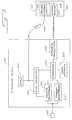
- FIG. 1is a block diagram of a medical diagnostic ultrasound imaging system and an ultrasound system peripheral of a preferred embodiment.
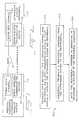
- FIG. 2is a flow chart of a method of communicating data and peripheral commands between a medical diagnostic ultrasound imaging system and an ultrasound system peripheral of a preferred embodiment.
- FIG. 3is a block diagram of a medical diagnostic ultrasound imaging system and an ultrasound system peripheral of another preferred embodiment.
- FIG. 4is a block diagram illustrating a peripheral interface of a preferred embodiment.
- FIG. 5is a block diagram illustrating a device library of a preferred embodiment.
- FIG. 6is an illustration of an ultrasound system of a preferred embodiment in which a forward-facing VCR is positioned on a top surface of an ultrasound system housing.
- FIG. 7is an illustration of an ultrasound system of a preferred embodiment in which a side-facing VCR is positioned on a top surface of an ultrasound system housing.
- FIG. 8is an illustration of an ultrasound system of a preferred embodiment in which two VCRs are positioned in openings formed in an ultrasound system housing.
- FIG. 9is an illustration of an ultrasound system of a preferred embodiment in which an infrared transmitter is integrally mounted in a housing of the ultrasound system.
- FIG. 10is an illustration of an ultrasound system of a preferred embodiment in which a wireless communication device is coupled with the system by a cable and is not integral to the ultrasound system housing.
- FIG. 1is a block diagram of a medical diagnostic ultrasound imaging system 10 and ultrasound system peripheral 100 of a presently preferred embodiment.
- the term “ultrasound system peripheral”broadly refers to any device that can be used with an ultrasound system.
- a peripheralcan be, for example, a video recording device, a video playback device, a video cassette recorder (VCR), a DVD player and/or recorder, a printer, a multi-image camera, a strip-chart recorder, a tape recorder, a desktop computer, a laptop computer, a handheld computer, or a robot.
- VCRvideo cassette recorder
- DVD player and/or recordera printer
- multi-image cameraa multi-image camera
- strip-chart recordera tape recorder
- desktop computera desktop computer
- laptop computera laptop computer
- a handheld computeror a robot.
- the ultrasound system 10comprises a first data channel 20 and a first wireless communication device 30 .
- the ultrasound system peripheral 100comprises a second data channel 120 and a second wireless communication device 130 .
- the first and second data channels 20 , 120are physically coupled with a data transmission medium 50 , through which data is transmitted between the ultrasound system 10 and peripheral 100 .
- the term “coupled with”means directly coupled with or indirectly coupled with through one or more components.
- the term “data transmission medium”is used to refer to any type of medium that can be used to physically couple the ultrasound system 10 with the peripheral 100 and that can transmit data therebetween. Examples of a data transmission medium include, but are not limited to, one or more wires, a single- or multi-wire cable, and a fiber optics connector.
- a preferred method for transmitting data and peripheral commands between the ultrasound system 10 and peripheral 100is shown in the flow chart 200 of FIG. 2 .
- datais transmitted between the ultrasound system 10 and the ultrasound system peripheral 100 via the data transmission medium 50 that physically couples the ultrasound system 10 and the peripheral 100 (act 210 ).
- commandsare not sent via the data transmission medium 50 .
- a peripheral commandis wirelessly transmitted from the ultrasound system 10 to the peripheral 100 (act 220 ).
- datais not wirelessly transmitted between the ultrasound system 10 and peripheral 100 .
- the peripheralperforms an operation in response to receipt of the peripheral command (act 230 ).
- an ultrasound peripheral operationcan be any operation or function that is performable by the peripheral.
- a peripheralcan be preprogrammed with one or more operations that are performed in response to the receipt of a command to perform the operation(s).
- peripheral commandis used herein to refer to any command that, upon receipt by the peripheral, causes the peripheral to perform an operation.
- a low-cost, consumer-grade VCR with an integral infrared receiver for receiving control signalscan be used instead of a more expensive, specialized VCR with a separate RS-232 command port.
- This illustrative applicationwill now be described in more detail with reference to FIG. 3 .
- FIG. 3is a block diagram of a medical diagnostic ultrasound imaging system 300 and ultrasound system peripheral 400 that illustrates one preferred implementation of the ultrasound system and peripheral shown in FIG. 1 .
- the ultrasound system 300comprises a transducer 305 , which is coupled with a transmit beamformer 310 and a receive beamformer 315 .
- the beamformers 310 , 315are each coupled with a processor 320 , which is coupled with a user interface 325 , a scan converter 330 , and an infrared transmitter 335 .
- the term “processor”broadly refers to any appropriate hardware and/or software component of the ultrasound system 300 that can be used to implement the preferred embodiments described herein.
- processor 320can be separate from or combined with (in part or in whole) other processors of the ultrasound system 300 (including attendant processors), which are not shown in FIG. 3 for simplicity.
- the processor 320can also include a memory device that stores software executable by the processor 320 .
- the processor 320causes the transmit beamformer 310 to apply a voltage to the transducer 305 to cause it to vibrate and emit an ultrasonic beam into an object, such as human tissue (i.e., a patient's body). Ultrasonic energy reflected from the body impinges on the transducer 305 , and the resulting voltages created by the transducer 305 are received by the receive beamformer 315 .
- the scan converter 330under control of the processor 320 , processes the sensed voltages to create an ultrasound image associated with the reflected signals and displays the image on a display 340 .
- the user interface 325can be used, for example, to adjust parameters used in the transmit, receive, and display operations. It should be noted that the ultrasound imaging system 300 can comprise additional components.
- the ultrasound system peripheral 400 of this presently preferred embodimenttakes the form of a VCR.
- the VCR 400comprises conventional record/playback circuitry 405 and an infrared receiver 410 .
- datais sent between the ultrasound system 300 and VCR 400 via a data transmission medium 450 , and peripheral commands are sent from the ultrasound system 300 to the peripheral 400 with the infrared transmitter 335 and are received by the peripheral 400 with the infrared receiver 410 .
- the user interface 325is used to communicate the “record” request.
- the user interface 325can be physically attached to the ultrasound system 300 , such as when the user interface 325 is a CRT touch-screen or a key, knob, button, slide, switch, trackball, and/or voice input device of the ultrasound system's console.
- the user interface 325can also be a remote control device dedicated to the ultrasound system (e.g., a wand or handheld controller), dedicated to the peripheral, or shared by the system and peripheral. For example, if the ultrasound system 300 has an infrared receiver and is sensitive to commands issued by the remote control of the VCR 400 , the VCR's remote control can be used to send an operation request to both the ultrasound system 300 and the VCR 400 .
- a userfirst presses a “record” button on the user interface 325 .
- the processor 320(or a microprocessor associated with the user interface 325 ) scans inputs from the user interface 325 , and when it receives a key press, for example, to record an image, the processor 320 sends video data from the scan converter 330 to the record/playback circuitry 405 of the VCR 400 .
- the processor 320also determines the appropriate coded infrared signal to be transmitted for a “record” command and sends that signal to the infrared transmitter 335 for transmission.
- the command signalcan be sent before, during, and/or after the transmission of data.
- the record/playback circuitry 405When the VCR 400 receives the “record” command, the record/playback circuitry 405 records the video signal on videotape.
- the processor 320sends a “play” command to the VCR 400 via the infrared transmitter 335 .
- the VCR 400Upon receipt of the “play” command, the VCR 400 sends video data to the ultrasound system 300 (either directly to the display 340 or indirectly through the scan converter 330 ) for display.
- the processor 320may be issuing other internal or external commands during this operation.
- the processor 320can switch video modes to allow the ultrasound system 300 to be able to display the incoming video data from the VCR 400 .
- the processor 320can be responsible for translating a peripheral operation requested via the user interface 325 to a peripheral command.
- the processor 320can execute a peripheral interface, which is, in this example, a look-up table that correlates operations requested by the ultrasound system 300 with infrared signals understood by the VCR 400 . For example, if a “record” operation is requested, the look-up table is indexed with the “record” request to determine the appropriate infrared signal to be sent to the infrared transmitter 335 for transmission.
- the same or a different peripheral interfacecan be used to translate information sent to the system by the peripheral.
- the peripheral interfacecan be used to translate coded infrared signals (such as operational status, tape status, counter information, etc.) received from the VCR.
- the processor 320can have a device library with a plurality of peripheral interfaces, each associated with a particular peripheral, as shown in FIG. 5 .
- the ultrasound system 300first identifies which peripheral it wants to control (the “library choice”), and then translates the requested operation into a peripheral command using the selected peripheral interface.
- the device librarycan store peripheral interfaces for different VCR manufacturers so that the ultrasound system will be able to communicate with any one of a number of VCRs without user input of device-specific control codes.
- a peripheralcan transmit (wirelessly or via the data transmission medium 450 ) an identification code that the ultrasound system can use to automatically select a peripheral interface from a device library.
- peripheral interfacescan be pre-installed in the ultrasound system, they can also be updated via, for example, a modem connection. Further, smart controllers can be used to learn the requirements of a particular peripheral device, reducing the need for upgrades to the device library.
- the requested commandcan also be issued by the ultrasound system itself, such as when an operation is automatically requested by the system.
- the ultrasound systemcan be programmed to automatically request a “record” operation in response to the occurrence of a selected imaging mode.
- the peripheral interfacewas described as a software application executed by the processor 320 .
- the peripheral interface functionalitycan also be implemented as hardware, separate from or part of the processor 320 .
- an EPROM, NVRAM, or NOVRAM programmed with the peripheral interface functionalitycan be used.
- a separate infrared control integrated circuitcan be used.
- One suitable integrated circuitis the IC4001TM universal infrared control integrated circuit from Innotech Systems Inc. (Port Jefferson, N.Y.), which includes a device library with peripheral interfaces for several VCRs.
- a medical diagnostic ultrasound imaging systemcomprises a housing that has an integral wireless communication device and a storage location defined by the housing and adapted to store an ultrasound system peripheral.
- the storage location and the wireless communication deviceare positioned in the housing to allow wireless communication between the wireless communication device and a wireless communication device of a peripheral stored in/by the storage location.
- the wireless communication devicecommunicates with infrared transmissions
- FIGS. 6-8illustrate this embodiment.
- the storage locationis the top surface of the housing 610
- the ultrasound peripheralis a forward-facing VCR 620 with an infrared receiver.
- the housing 610comprises an infrared transmitter 630 integral with the housing 610 and coupled with a processor (not shown). This arrangement provides an unimpeded optical path between the infrared transmitter 630 of the housing 610 and the infrared receiver of the VCR 620 .
- FIG. 6also shows other suitable locations 622 , 624 , 626 on the ultrasound system's console for the infrared transmitter.
- the VCR 720is side facing, and the infrared transmitter 730 is located adjacent the VCR 720 when the VCR 720 is stored on the top surface of the housing 710 .
- FIG. 7the VCR 720 is side facing
- forward-facing and side-facing VCRs 820 , 825are stored in two openings within the housing 810 .
- Infrared transmitters 830 , 835 mounted in the housing 810are located near the infrared receivers of the VCRs 820 , 825 .
- FIG. 9is an illustration showing one preferred way in which an infrared transmitter can be integrally mounted to the housing.
- the infrared transmitter 910is coupled with the ultrasound system's processor (not shown) with a cable 915 .
- An infrared lens 920is mounted over the transmitter 910 to aim infrared transmission to an infrared receiver of a forward-facing VCR 925 .
- the command sent to the peripheralcaused the peripheral to perform a function related to the data sent between the ultrasound system and peripheral.
- the function performed by a peripheral in response to a commandis not associated with data sent between the ultrasound system and peripheral, if data is sent at all (such as when a “fast forward” command is sent).
- one or more wireless communication devicescan be used by the ultrasound system to communicate with the peripherals.
- the peripheralcan send an ultrasound system command to the ultrasound system.
- Thisallows for bi-directional control between the ultrasound system and peripheral.
- the ultrasound systemreceives the ultrasound system command, it performs an ultrasound system operation associated with the command.
- the ultrasound systemcan have a peripheral interface (or a device library of peripheral interfaces) to translate the ultrasound system command into an ultrasound system operation.
- an ultrasound system operationcan be any operation or function that is performable by the ultrasound system.
- the “ultrasound system operation”can simply be the selection of a peripheral interface in response to the ultrasound system receiving a “command” from the peripheral identifying its model type.
- the term “ultrasound system command”is used herein to refer to any command that, upon receipt by the ultrasound system, causes the ultrasound system to perform an operation.
- a medical diagnostic ultrasound imaging system with a first wireless communication deviceis used to transmit a peripheral command via the first wireless communication device to an ultrasound system peripheral.
- the ultrasound system peripheralhas a second wireless communication device that is integral with the peripheral (ie., the peripheral and the second wireless communication device are in the same housing).
- the ultrasound system peripheralis operative to perform an operation in response to receipt, via the second wireless communication device, of the peripheral command.
- the use of a data transmission medium to physically couple and communicate data between the ultrasound system and the peripheralis optional.
- wireless communication devicehas been used to broadly refer to any device that has the ability to transmit information, preferably an ultrasound peripheral command, from one point to another without the use of a physical connection.
- the wireless communication devicecan be integral with the ultrasound system or peripheral, such as when the peripheral contains a built-in infrared receiver.
- the wireless communication devicecan also be an add-on component to the ultrasound system or peripheral, such as when the wireless communication device 1010 of the ultrasound system 1000 is a detachable accessory that is tethered to the system, as shown in FIG. 10.
- a wireless communication devicecan include an emitter, receiver, or transceiver.
- the wireless communication devicebe able to communicate virtually simultaneously in receive and transmit modes (e.g., by time-slicing between operations) and be able to communicate virtually simultaneously with more than one peripheral device (e.g., by time-slicing between peripheral devices).
- Example of wireless communication devicesinclude, but are not limited to, devices that communicate information using infrared, radio frequency, light wave, microwave, or ultrasonic transmissions.
- suitable infrared detectorse.g., photo diodes or photo transistors
- the detectorcan also take the form of an infrared photomodule, such as part number TSOP1838 from Vishay Telefunken and part number SFH5110 from Infineon Technologies.
- suitable infrared emittersinclude part number TSAL6200 from Vishay Telefunken, part number HSPL-4200 from Hewlett-Packard, and part number SFH426 from Infineon Technologies.
- the peripheralis compatible with the IrDA infrared communication protocol developed by the Infrared Data Association.
- IrDA peripheral devicesprovide a walk-up, point-to-point method of data transfer that is adaptable to a broad range of computing and communication devices.
- Version 1.1 of the IrDA infrared communication protocolprovides for communication at data rates up to 4 Megabytes per second.
- the IrDA infrared communication protocolalso defines a set of specifications, or protocol stack, that provides for the establishment and maintenance of a link so that error free communication is possible.
- IrDA infrared communication protocolsinclude: I/O controllers, transceivers, receivers, encoder boards, notebook/portable/desktop computers, handheld personal data assistants (PDAs), adapters, printers, telephones, network access equipment, modems, keyboards, computer mice and other remote control devices.
- PDAspersonal data assistants
- IrDA Data Compliant infrared transceiversare part number TFDT6501E from Vishay Telefunken, part number HSPL-3610 from Hewlett-Packard and part number IRMT6400 from Infineon Technologies.
Landscapes
- Life Sciences & Earth Sciences (AREA)
- Health & Medical Sciences (AREA)
- Biomedical Technology (AREA)
- Biophysics (AREA)
- Nuclear Medicine, Radiotherapy & Molecular Imaging (AREA)
- Pathology (AREA)
- Radiology & Medical Imaging (AREA)
- Engineering & Computer Science (AREA)
- Physics & Mathematics (AREA)
- Heart & Thoracic Surgery (AREA)
- Medical Informatics (AREA)
- Molecular Biology (AREA)
- Surgery (AREA)
- Animal Behavior & Ethology (AREA)
- General Health & Medical Sciences (AREA)
- Public Health (AREA)
- Veterinary Medicine (AREA)
- Ultra Sonic Daignosis Equipment (AREA)
Abstract
Description
Claims (35)
Priority Applications (1)
| Application Number | Priority Date | Filing Date | Title |
|---|---|---|---|
| US09/538,449US6238344B1 (en) | 2000-03-30 | 2000-03-30 | Medical diagnostic ultrasound imaging system with a wirelessly-controlled peripheral |
Applications Claiming Priority (1)
| Application Number | Priority Date | Filing Date | Title |
|---|---|---|---|
| US09/538,449US6238344B1 (en) | 2000-03-30 | 2000-03-30 | Medical diagnostic ultrasound imaging system with a wirelessly-controlled peripheral |
Publications (1)
| Publication Number | Publication Date |
|---|---|
| US6238344B1true US6238344B1 (en) | 2001-05-29 |
Family
ID=24146978
Family Applications (1)
| Application Number | Title | Priority Date | Filing Date |
|---|---|---|---|
| US09/538,449Expired - LifetimeUS6238344B1 (en) | 2000-03-30 | 2000-03-30 | Medical diagnostic ultrasound imaging system with a wirelessly-controlled peripheral |
Country Status (1)
| Country | Link |
|---|---|
| US (1) | US6238344B1 (en) |
Cited By (78)
| Publication number | Priority date | Publication date | Assignee | Title |
|---|---|---|---|---|
| US6424525B1 (en)* | 1999-08-27 | 2002-07-23 | Stratos Product Development Llc | External peripheral attachment device for use as a hub or computer |
| US20020128846A1 (en)* | 2001-03-12 | 2002-09-12 | Miller Steven C. | Remote control of a medical device using voice recognition and foot controls |
| US6471648B1 (en)* | 2000-07-17 | 2002-10-29 | Acuson Corporation | Medical diagnostic ultrasound imaging system with a rotatable user interface element having a non-rotatable indicator |
| US6514201B1 (en)* | 1999-01-29 | 2003-02-04 | Acuson Corporation | Voice-enhanced diagnostic medical ultrasound system and review station |
| US6540685B1 (en)* | 2000-11-09 | 2003-04-01 | Koninklijke Philips Electronics N.V. | Ultrasound diagnostic device |
| US6569097B1 (en)* | 2000-07-21 | 2003-05-27 | Diagnostics Ultrasound Corporation | System for remote evaluation of ultrasound information obtained by a programmed application-specific data collection device |
| US20030160755A1 (en)* | 2002-02-28 | 2003-08-28 | Palm, Inc. | Detachable expandable flexible display |
| US20040127797A1 (en)* | 2002-06-07 | 2004-07-01 | Bill Barnard | System and method for measuring bladder wall thickness and presenting a bladder virtual image |
| US20040184618A1 (en)* | 2003-03-21 | 2004-09-23 | Gn Resound A/S | Modular wireless auditory test instrument with intelligent transducers |
| US20040254753A1 (en)* | 2003-04-02 | 2004-12-16 | Gn Resound A/S | Multimedia auditory test instrument |
| US6857032B2 (en)* | 2000-03-28 | 2005-02-15 | Pentax Corporation | Image data input device |
| US20050038314A1 (en)* | 2003-08-13 | 2005-02-17 | Falk Steven M. | Infrared communication with infant care apparatus |
| US20050114568A1 (en)* | 2003-11-26 | 2005-05-26 | Israel Raz | Methods and systems for managing outputs to peripheral devices |
| US20050262921A1 (en)* | 2004-05-28 | 2005-12-01 | Arntz Robert T | Tone wheel sensor tester |
| US20050265267A1 (en)* | 2004-05-17 | 2005-12-01 | Sonosite, Inc. | Processing of medical signals |
| US20060025689A1 (en)* | 2002-06-07 | 2006-02-02 | Vikram Chalana | System and method to measure cardiac ejection fraction |
| US20060191315A1 (en)* | 2004-03-29 | 2006-08-31 | Siemens Medical Solutions Usa, Inc. | Ultrasound transmit and receive path calibration methods and systems |
| US7135987B1 (en) | 2002-06-03 | 2006-11-14 | Gsi Group Corporation | Wireless chart recorder system and method |
| US20070071266A1 (en)* | 2004-08-24 | 2007-03-29 | Sonosite, Inc. | Ultrasonic transducer having a digital interface |
| US20070232908A1 (en)* | 2002-06-07 | 2007-10-04 | Yanwei Wang | Systems and methods to improve clarity in ultrasound images |
| US20070276254A1 (en)* | 2002-06-07 | 2007-11-29 | Fuxing Yang | System and method to identify and measure organ wall boundaries |
| US20080032755A1 (en)* | 2002-02-28 | 2008-02-07 | Palm, Inc. | Interchangeable display modules for portable handheld devices |
| US20080114251A1 (en)* | 2006-11-10 | 2008-05-15 | Penrith Corporation | Transducer array imaging system |
| US20080238813A1 (en)* | 2001-11-28 | 2008-10-02 | Palm, Inc. | Computing device and display for computing device |
| US20080242985A1 (en)* | 2003-05-20 | 2008-10-02 | Vikram Chalana | 3d ultrasound-based instrument for non-invasive measurement of amniotic fluid volume |
| US20080262356A1 (en)* | 2002-06-07 | 2008-10-23 | Vikram Chalana | Systems and methods for ultrasound imaging using an inertial reference unit |
| US20090062644A1 (en)* | 2002-06-07 | 2009-03-05 | Mcmorrow Gerald | System and method for ultrasound harmonic imaging |
| US20090112089A1 (en)* | 2007-10-27 | 2009-04-30 | Bill Barnard | System and method for measuring bladder wall thickness and presenting a bladder virtual image |
| US7549961B1 (en) | 2003-07-31 | 2009-06-23 | Sonosite, Inc. | System and method supporting imaging and monitoring applications |
| US20090176481A1 (en)* | 2008-01-04 | 2009-07-09 | Palm, Inc. | Providing Location-Based Services (LBS) Through Remote Display |
| US20090264757A1 (en)* | 2007-05-16 | 2009-10-22 | Fuxing Yang | System and method for bladder detection using harmonic imaging |
| US20100006649A1 (en)* | 2008-07-11 | 2010-01-14 | Steve Bolton | Secure Ballot Box |
| US20100036242A1 (en)* | 2007-05-16 | 2010-02-11 | Jongtae Yuk | Device, system and method to measure abdominal aortic aneurysm diameter |
| US20100036252A1 (en)* | 2002-06-07 | 2010-02-11 | Vikram Chalana | Ultrasound system and method for measuring bladder wall thickness and mass |
| US20100198075A1 (en)* | 2002-08-09 | 2010-08-05 | Verathon Inc. | Instantaneous ultrasonic echo measurement of bladder volume with a limited number of ultrasound beams |
| US7794407B2 (en) | 2006-10-23 | 2010-09-14 | Bard Access Systems, Inc. | Method of locating the tip of a central venous catheter |
| US8221321B2 (en) | 2002-06-07 | 2012-07-17 | Verathon Inc. | Systems and methods for quantification and classification of fluids in human cavities in ultrasound images |
| US8388546B2 (en) | 2006-10-23 | 2013-03-05 | Bard Access Systems, Inc. | Method of locating the tip of a central venous catheter |
| US8388541B2 (en) | 2007-11-26 | 2013-03-05 | C. R. Bard, Inc. | Integrated system for intravascular placement of a catheter |
| US8437833B2 (en) | 2008-10-07 | 2013-05-07 | Bard Access Systems, Inc. | Percutaneous magnetic gastrostomy |
| US8478382B2 (en) | 2008-02-11 | 2013-07-02 | C. R. Bard, Inc. | Systems and methods for positioning a catheter |
| US20130226001A1 (en)* | 2012-02-27 | 2013-08-29 | General Electric Company | Method and apparatus for performing ultrasound imaging |
| USD699359S1 (en) | 2011-08-09 | 2014-02-11 | C. R. Bard, Inc. | Ultrasound probe head |
| US8781555B2 (en) | 2007-11-26 | 2014-07-15 | C. R. Bard, Inc. | System for placement of a catheter including a signal-generating stylet |
| US8784336B2 (en) | 2005-08-24 | 2014-07-22 | C. R. Bard, Inc. | Stylet apparatuses and methods of manufacture |
| US8801693B2 (en) | 2010-10-29 | 2014-08-12 | C. R. Bard, Inc. | Bioimpedance-assisted placement of a medical device |
| US8849382B2 (en) | 2007-11-26 | 2014-09-30 | C. R. Bard, Inc. | Apparatus and display methods relating to intravascular placement of a catheter |
| USD724745S1 (en) | 2011-08-09 | 2015-03-17 | C. R. Bard, Inc. | Cap for an ultrasound probe |
| US20150131963A1 (en)* | 2013-09-13 | 2015-05-14 | Abbott Medical Optics Inc. | Apparatus, system and method for consolidating and recording high definition surgical video with a surgical data overlay |
| US9125578B2 (en) | 2009-06-12 | 2015-09-08 | Bard Access Systems, Inc. | Apparatus and method for catheter navigation and tip location |
| US9211107B2 (en) | 2011-11-07 | 2015-12-15 | C. R. Bard, Inc. | Ruggedized ultrasound hydrogel insert |
| US20150374346A1 (en)* | 2013-02-15 | 2015-12-31 | B-K Medical Aps | Ultrasound display client |
| US9295444B2 (en) | 2006-11-10 | 2016-03-29 | Siemens Medical Solutions Usa, Inc. | Transducer array imaging system |
| US9339206B2 (en) | 2009-06-12 | 2016-05-17 | Bard Access Systems, Inc. | Adaptor for endovascular electrocardiography |
| US20160174937A1 (en)* | 2014-12-23 | 2016-06-23 | General Electric Company | Wireless ultrasound probe |
| US9445734B2 (en) | 2009-06-12 | 2016-09-20 | Bard Access Systems, Inc. | Devices and methods for endovascular electrography |
| US9456766B2 (en) | 2007-11-26 | 2016-10-04 | C. R. Bard, Inc. | Apparatus for use with needle insertion guidance system |
| US9492097B2 (en) | 2007-11-26 | 2016-11-15 | C. R. Bard, Inc. | Needle length determination and calibration for insertion guidance system |
| US9521961B2 (en) | 2007-11-26 | 2016-12-20 | C. R. Bard, Inc. | Systems and methods for guiding a medical instrument |
| US9532724B2 (en) | 2009-06-12 | 2017-01-03 | Bard Access Systems, Inc. | Apparatus and method for catheter navigation using endovascular energy mapping |
| US9554716B2 (en) | 2007-11-26 | 2017-01-31 | C. R. Bard, Inc. | Insertion guidance system for needles and medical components |
| US9636031B2 (en) | 2007-11-26 | 2017-05-02 | C.R. Bard, Inc. | Stylets for use with apparatus for intravascular placement of a catheter |
| US9649048B2 (en) | 2007-11-26 | 2017-05-16 | C. R. Bard, Inc. | Systems and methods for breaching a sterile field for intravascular placement of a catheter |
| US9839372B2 (en) | 2014-02-06 | 2017-12-12 | C. R. Bard, Inc. | Systems and methods for guidance and placement of an intravascular device |
| US20180049722A1 (en)* | 2015-03-25 | 2018-02-22 | Hitachi, Ltd. | Ultrasonic diagnosis system |
| US9901714B2 (en) | 2008-08-22 | 2018-02-27 | C. R. Bard, Inc. | Catheter assembly including ECG sensor and magnetic assemblies |
| US10046139B2 (en) | 2010-08-20 | 2018-08-14 | C. R. Bard, Inc. | Reconfirmation of ECG-assisted catheter tip placement |
| US10349890B2 (en) | 2015-06-26 | 2019-07-16 | C. R. Bard, Inc. | Connector interface for ECG-based catheter positioning system |
| US10449330B2 (en) | 2007-11-26 | 2019-10-22 | C. R. Bard, Inc. | Magnetic element-equipped needle assemblies |
| US10524691B2 (en) | 2007-11-26 | 2020-01-07 | C. R. Bard, Inc. | Needle assembly including an aligned magnetic element |
| US10639008B2 (en) | 2009-10-08 | 2020-05-05 | C. R. Bard, Inc. | Support and cover structures for an ultrasound probe head |
| US10751509B2 (en) | 2007-11-26 | 2020-08-25 | C. R. Bard, Inc. | Iconic representations for guidance of an indwelling medical device |
| US10820885B2 (en) | 2012-06-15 | 2020-11-03 | C. R. Bard, Inc. | Apparatus and methods for detection of a removable cap on an ultrasound probe |
| US10973584B2 (en) | 2015-01-19 | 2021-04-13 | Bard Access Systems, Inc. | Device and method for vascular access |
| US10992079B2 (en) | 2018-10-16 | 2021-04-27 | Bard Access Systems, Inc. | Safety-equipped connection systems and methods thereof for establishing electrical connections |
| US11000207B2 (en) | 2016-01-29 | 2021-05-11 | C. R. Bard, Inc. | Multiple coil system for tracking a medical device |
| US11103213B2 (en) | 2009-10-08 | 2021-08-31 | C. R. Bard, Inc. | Spacers for use with an ultrasound probe |
| US11363978B2 (en) | 2018-05-24 | 2022-06-21 | Verathon Inc. | Bladder monitoring system |
Citations (18)
| Publication number | Priority date | Publication date | Assignee | Title |
|---|---|---|---|---|
| US3972320A (en) | 1974-08-12 | 1976-08-03 | Gabor Ujhelyi Kalman | Patient monitoring system |
| US4100916A (en) | 1976-04-27 | 1978-07-18 | King Donald L | Three-dimensional ultrasonic imaging of animal soft tissue |
| US4413629A (en) | 1982-04-22 | 1983-11-08 | Cryomedics, Inc. | Portable ultrasonic Doppler System |
| EP0123456A2 (en)* | 1983-03-28 | 1984-10-31 | Compression Labs, Inc. | A combined intraframe and interframe transform coding method |
| US4522213A (en) | 1983-01-25 | 1985-06-11 | Dragerwerk Aktiengesellschaft | Monitoring device for medical apparatus |
| US4974607A (en) | 1987-08-20 | 1990-12-04 | Satoru Miwa | System for centralized management of medical data |
| US5291399A (en) | 1990-07-27 | 1994-03-01 | Executone Information Systems, Inc. | Method and apparatus for accessing a portable personal database as for a hospital environment |
| US5603323A (en) | 1996-02-27 | 1997-02-18 | Advanced Technology Laboratories, Inc. | Medical ultrasonic diagnostic system with upgradeable transducer probes and other features |
| US5640960A (en) | 1995-04-18 | 1997-06-24 | Imex Medical Systems, Inc. | Hand-held, battery operated, doppler ultrasound medical diagnostic device with cordless probe |
| US5715823A (en) | 1996-02-27 | 1998-02-10 | Atlantis Diagnostics International, L.L.C. | Ultrasonic diagnostic imaging system with universal access to diagnostic information and images |
| US5778177A (en) | 1994-09-28 | 1998-07-07 | At&T Corp. | Interactive scanning device or system |
| US5851186A (en) | 1996-02-27 | 1998-12-22 | Atl Ultrasound, Inc. | Ultrasonic diagnostic imaging system with universal access to diagnostic information and images |
| US5865733A (en)* | 1997-02-28 | 1999-02-02 | Spacelabs Medical, Inc. | Wireless optical patient monitoring apparatus |
| US5867821A (en) | 1994-05-11 | 1999-02-02 | Paxton Developments Inc. | Method and apparatus for electronically accessing and distributing personal health care information and services in hospitals and homes |
| US5891035A (en) | 1996-09-25 | 1999-04-06 | Atl Ultrasound, Inc. | Ultrasonic diagnostic imaging system with data access and communications capability |
| US5944659A (en) | 1995-11-13 | 1999-08-31 | Vitalcom Inc. | Architecture for TDMA medical telemetry system |
| US5957854A (en)* | 1993-09-04 | 1999-09-28 | Besson; Marcus | Wireless medical diagnosis and monitoring equipment |
| US5964709A (en) | 1995-06-29 | 1999-10-12 | Teratech Corporation | Portable ultrasound imaging system |
- 2000
- 2000-03-30USUS09/538,449patent/US6238344B1/ennot_activeExpired - Lifetime
Patent Citations (18)
| Publication number | Priority date | Publication date | Assignee | Title |
|---|---|---|---|---|
| US3972320A (en) | 1974-08-12 | 1976-08-03 | Gabor Ujhelyi Kalman | Patient monitoring system |
| US4100916A (en) | 1976-04-27 | 1978-07-18 | King Donald L | Three-dimensional ultrasonic imaging of animal soft tissue |
| US4413629A (en) | 1982-04-22 | 1983-11-08 | Cryomedics, Inc. | Portable ultrasonic Doppler System |
| US4522213A (en) | 1983-01-25 | 1985-06-11 | Dragerwerk Aktiengesellschaft | Monitoring device for medical apparatus |
| EP0123456A2 (en)* | 1983-03-28 | 1984-10-31 | Compression Labs, Inc. | A combined intraframe and interframe transform coding method |
| US4974607A (en) | 1987-08-20 | 1990-12-04 | Satoru Miwa | System for centralized management of medical data |
| US5291399A (en) | 1990-07-27 | 1994-03-01 | Executone Information Systems, Inc. | Method and apparatus for accessing a portable personal database as for a hospital environment |
| US5957854A (en)* | 1993-09-04 | 1999-09-28 | Besson; Marcus | Wireless medical diagnosis and monitoring equipment |
| US5867821A (en) | 1994-05-11 | 1999-02-02 | Paxton Developments Inc. | Method and apparatus for electronically accessing and distributing personal health care information and services in hospitals and homes |
| US5778177A (en) | 1994-09-28 | 1998-07-07 | At&T Corp. | Interactive scanning device or system |
| US5640960A (en) | 1995-04-18 | 1997-06-24 | Imex Medical Systems, Inc. | Hand-held, battery operated, doppler ultrasound medical diagnostic device with cordless probe |
| US5964709A (en) | 1995-06-29 | 1999-10-12 | Teratech Corporation | Portable ultrasound imaging system |
| US5944659A (en) | 1995-11-13 | 1999-08-31 | Vitalcom Inc. | Architecture for TDMA medical telemetry system |
| US5851186A (en) | 1996-02-27 | 1998-12-22 | Atl Ultrasound, Inc. | Ultrasonic diagnostic imaging system with universal access to diagnostic information and images |
| US5715823A (en) | 1996-02-27 | 1998-02-10 | Atlantis Diagnostics International, L.L.C. | Ultrasonic diagnostic imaging system with universal access to diagnostic information and images |
| US5603323A (en) | 1996-02-27 | 1997-02-18 | Advanced Technology Laboratories, Inc. | Medical ultrasonic diagnostic system with upgradeable transducer probes and other features |
| US5891035A (en) | 1996-09-25 | 1999-04-06 | Atl Ultrasound, Inc. | Ultrasonic diagnostic imaging system with data access and communications capability |
| US5865733A (en)* | 1997-02-28 | 1999-02-02 | Spacelabs Medical, Inc. | Wireless optical patient monitoring apparatus |
Cited By (140)
| Publication number | Priority date | Publication date | Assignee | Title |
|---|---|---|---|---|
| US6743175B2 (en) | 1999-01-29 | 2004-06-01 | Acuson Corporation | Voice-enhanced diagnostic medical ultrasound system and review station |
| US6514201B1 (en)* | 1999-01-29 | 2003-02-04 | Acuson Corporation | Voice-enhanced diagnostic medical ultrasound system and review station |
| US6424525B1 (en)* | 1999-08-27 | 2002-07-23 | Stratos Product Development Llc | External peripheral attachment device for use as a hub or computer |
| US6857032B2 (en)* | 2000-03-28 | 2005-02-15 | Pentax Corporation | Image data input device |
| US6471648B1 (en)* | 2000-07-17 | 2002-10-29 | Acuson Corporation | Medical diagnostic ultrasound imaging system with a rotatable user interface element having a non-rotatable indicator |
| WO2002007586A3 (en)* | 2000-07-21 | 2003-07-10 | Diagnostic Ultrasound Corp | System for remote programming of ultrasound devices |
| US6569097B1 (en)* | 2000-07-21 | 2003-05-27 | Diagnostics Ultrasound Corporation | System for remote evaluation of ultrasound information obtained by a programmed application-specific data collection device |
| US6540685B1 (en)* | 2000-11-09 | 2003-04-01 | Koninklijke Philips Electronics N.V. | Ultrasound diagnostic device |
| US20020128846A1 (en)* | 2001-03-12 | 2002-09-12 | Miller Steven C. | Remote control of a medical device using voice recognition and foot controls |
| US7127401B2 (en) | 2001-03-12 | 2006-10-24 | Ge Medical Systems Global Technology Company, Llc | Remote control of a medical device using speech recognition and foot controls |
| US20080238813A1 (en)* | 2001-11-28 | 2008-10-02 | Palm, Inc. | Computing device and display for computing device |
| US7884815B2 (en) | 2002-02-28 | 2011-02-08 | Palm, Inc. | Interchangeable display modules for portable handheld devices |
| US20030160755A1 (en)* | 2002-02-28 | 2003-08-28 | Palm, Inc. | Detachable expandable flexible display |
| US7342571B2 (en) | 2002-02-28 | 2008-03-11 | Palm, Inc. | Interchangeable display modules for portable handheld devices |
| US20080032755A1 (en)* | 2002-02-28 | 2008-02-07 | Palm, Inc. | Interchangeable display modules for portable handheld devices |
| US7135987B1 (en) | 2002-06-03 | 2006-11-14 | Gsi Group Corporation | Wireless chart recorder system and method |
| US20070232908A1 (en)* | 2002-06-07 | 2007-10-04 | Yanwei Wang | Systems and methods to improve clarity in ultrasound images |
| US20060025689A1 (en)* | 2002-06-07 | 2006-02-02 | Vikram Chalana | System and method to measure cardiac ejection fraction |
| US20100036252A1 (en)* | 2002-06-07 | 2010-02-11 | Vikram Chalana | Ultrasound system and method for measuring bladder wall thickness and mass |
| US8221321B2 (en) | 2002-06-07 | 2012-07-17 | Verathon Inc. | Systems and methods for quantification and classification of fluids in human cavities in ultrasound images |
| US8221322B2 (en) | 2002-06-07 | 2012-07-17 | Verathon Inc. | Systems and methods to improve clarity in ultrasound images |
| US20090062644A1 (en)* | 2002-06-07 | 2009-03-05 | Mcmorrow Gerald | System and method for ultrasound harmonic imaging |
| US20080262356A1 (en)* | 2002-06-07 | 2008-10-23 | Vikram Chalana | Systems and methods for ultrasound imaging using an inertial reference unit |
| US7819806B2 (en) | 2002-06-07 | 2010-10-26 | Verathon Inc. | System and method to identify and measure organ wall boundaries |
| US20070276254A1 (en)* | 2002-06-07 | 2007-11-29 | Fuxing Yang | System and method to identify and measure organ wall boundaries |
| US20040127797A1 (en)* | 2002-06-07 | 2004-07-01 | Bill Barnard | System and method for measuring bladder wall thickness and presenting a bladder virtual image |
| US20100198075A1 (en)* | 2002-08-09 | 2010-08-05 | Verathon Inc. | Instantaneous ultrasonic echo measurement of bladder volume with a limited number of ultrasound beams |
| US8308644B2 (en) | 2002-08-09 | 2012-11-13 | Verathon Inc. | Instantaneous ultrasonic measurement of bladder volume |
| US9993225B2 (en) | 2002-08-09 | 2018-06-12 | Verathon Inc. | Instantaneous ultrasonic echo measurement of bladder volume with a limited number of ultrasound beams |
| US20110135104A1 (en)* | 2003-03-21 | 2011-06-09 | Gn Resound A/S | Modular wireless auditory test instrument with intelligent transducers |
| US7965851B2 (en) | 2003-03-21 | 2011-06-21 | Gn Resound A/S | Modular wireless auditory test instrument with intelligent transducers |
| US8983084B2 (en) | 2003-03-21 | 2015-03-17 | Gn Resound A/S | Modular wireless auditory test instrument with intelligent transducers |
| US20040184618A1 (en)* | 2003-03-21 | 2004-09-23 | Gn Resound A/S | Modular wireless auditory test instrument with intelligent transducers |
| US20040254753A1 (en)* | 2003-04-02 | 2004-12-16 | Gn Resound A/S | Multimedia auditory test instrument |
| US20080242985A1 (en)* | 2003-05-20 | 2008-10-02 | Vikram Chalana | 3d ultrasound-based instrument for non-invasive measurement of amniotic fluid volume |
| US7549961B1 (en) | 2003-07-31 | 2009-06-23 | Sonosite, Inc. | System and method supporting imaging and monitoring applications |
| US20050038314A1 (en)* | 2003-08-13 | 2005-02-17 | Falk Steven M. | Infrared communication with infant care apparatus |
| US7734840B2 (en) | 2003-11-26 | 2010-06-08 | Ge Medical Systems Global Technology Co., Llc | Methods and systems for managing outputs to peripheral devices |
| FR2862779A1 (en)* | 2003-11-26 | 2005-05-27 | Ge Med Sys Global Tech Co Llc | Peripheral device output management method e.g. for printer, involves storing data object in memory if peripheral device that provides output is not available to accept data object |
| US20050114568A1 (en)* | 2003-11-26 | 2005-05-26 | Israel Raz | Methods and systems for managing outputs to peripheral devices |
| US7162912B2 (en) | 2004-03-29 | 2007-01-16 | Siemens Medical Solutions Usa, Inc. | Ultrasound transmit and receive path calibration methods and systems |
| US20060191315A1 (en)* | 2004-03-29 | 2006-08-31 | Siemens Medical Solutions Usa, Inc. | Ultrasound transmit and receive path calibration methods and systems |
| US7266987B2 (en) | 2004-03-29 | 2007-09-11 | Siemens Medical Solutions Usa, Inc. | Ultrasound transmit and receive path calibration methods and systems |
| US20050265267A1 (en)* | 2004-05-17 | 2005-12-01 | Sonosite, Inc. | Processing of medical signals |
| US7809400B1 (en) | 2004-05-17 | 2010-10-05 | Sonosite, Inc. | Processing of medical signals |
| US8199685B2 (en) | 2004-05-17 | 2012-06-12 | Sonosite, Inc. | Processing of medical signals |
| US20050262921A1 (en)* | 2004-05-28 | 2005-12-01 | Arntz Robert T | Tone wheel sensor tester |
| US20070071266A1 (en)* | 2004-08-24 | 2007-03-29 | Sonosite, Inc. | Ultrasonic transducer having a digital interface |
| US7867168B2 (en) | 2004-08-24 | 2011-01-11 | Sonosite, Inc. | Ultrasonic transducer having distributed weight properties |
| US8784336B2 (en) | 2005-08-24 | 2014-07-22 | C. R. Bard, Inc. | Stylet apparatuses and methods of manufacture |
| US10004875B2 (en) | 2005-08-24 | 2018-06-26 | C. R. Bard, Inc. | Stylet apparatuses and methods of manufacture |
| US11207496B2 (en) | 2005-08-24 | 2021-12-28 | C. R. Bard, Inc. | Stylet apparatuses and methods of manufacture |
| US9265443B2 (en) | 2006-10-23 | 2016-02-23 | Bard Access Systems, Inc. | Method of locating the tip of a central venous catheter |
| US9345422B2 (en) | 2006-10-23 | 2016-05-24 | Bard Acess Systems, Inc. | Method of locating the tip of a central venous catheter |
| US8858455B2 (en) | 2006-10-23 | 2014-10-14 | Bard Access Systems, Inc. | Method of locating the tip of a central venous catheter |
| US8774907B2 (en) | 2006-10-23 | 2014-07-08 | Bard Access Systems, Inc. | Method of locating the tip of a central venous catheter |
| US8388546B2 (en) | 2006-10-23 | 2013-03-05 | Bard Access Systems, Inc. | Method of locating the tip of a central venous catheter |
| US8512256B2 (en) | 2006-10-23 | 2013-08-20 | Bard Access Systems, Inc. | Method of locating the tip of a central venous catheter |
| US9833169B2 (en) | 2006-10-23 | 2017-12-05 | Bard Access Systems, Inc. | Method of locating the tip of a central venous catheter |
| US7794407B2 (en) | 2006-10-23 | 2010-09-14 | Bard Access Systems, Inc. | Method of locating the tip of a central venous catheter |
| US9295444B2 (en) | 2006-11-10 | 2016-03-29 | Siemens Medical Solutions Usa, Inc. | Transducer array imaging system |
| US20080114251A1 (en)* | 2006-11-10 | 2008-05-15 | Penrith Corporation | Transducer array imaging system |
| US20090264757A1 (en)* | 2007-05-16 | 2009-10-22 | Fuxing Yang | System and method for bladder detection using harmonic imaging |
| US8133181B2 (en) | 2007-05-16 | 2012-03-13 | Verathon Inc. | Device, system and method to measure abdominal aortic aneurysm diameter |
| US8167803B2 (en) | 2007-05-16 | 2012-05-01 | Verathon Inc. | System and method for bladder detection using harmonic imaging |
| US20100036242A1 (en)* | 2007-05-16 | 2010-02-11 | Jongtae Yuk | Device, system and method to measure abdominal aortic aneurysm diameter |
| US20090112089A1 (en)* | 2007-10-27 | 2009-04-30 | Bill Barnard | System and method for measuring bladder wall thickness and presenting a bladder virtual image |
| US10342575B2 (en) | 2007-11-26 | 2019-07-09 | C. R. Bard, Inc. | Apparatus for use with needle insertion guidance system |
| US9681823B2 (en) | 2007-11-26 | 2017-06-20 | C. R. Bard, Inc. | Integrated system for intravascular placement of a catheter |
| US8781555B2 (en) | 2007-11-26 | 2014-07-15 | C. R. Bard, Inc. | System for placement of a catheter including a signal-generating stylet |
| US9999371B2 (en) | 2007-11-26 | 2018-06-19 | C. R. Bard, Inc. | Integrated system for intravascular placement of a catheter |
| US11779240B2 (en) | 2007-11-26 | 2023-10-10 | C. R. Bard, Inc. | Systems and methods for breaching a sterile field for intravascular placement of a catheter |
| US9492097B2 (en) | 2007-11-26 | 2016-11-15 | C. R. Bard, Inc. | Needle length determination and calibration for insertion guidance system |
| US11529070B2 (en) | 2007-11-26 | 2022-12-20 | C. R. Bard, Inc. | System and methods for guiding a medical instrument |
| US8388541B2 (en) | 2007-11-26 | 2013-03-05 | C. R. Bard, Inc. | Integrated system for intravascular placement of a catheter |
| US11134915B2 (en) | 2007-11-26 | 2021-10-05 | C. R. Bard, Inc. | System for placement of a catheter including a signal-generating stylet |
| US11123099B2 (en) | 2007-11-26 | 2021-09-21 | C. R. Bard, Inc. | Apparatus for use with needle insertion guidance system |
| US10105121B2 (en) | 2007-11-26 | 2018-10-23 | C. R. Bard, Inc. | System for placement of a catheter including a signal-generating stylet |
| US10966630B2 (en) | 2007-11-26 | 2021-04-06 | C. R. Bard, Inc. | Integrated system for intravascular placement of a catheter |
| US10849695B2 (en) | 2007-11-26 | 2020-12-01 | C. R. Bard, Inc. | Systems and methods for breaching a sterile field for intravascular placement of a catheter |
| US10751509B2 (en) | 2007-11-26 | 2020-08-25 | C. R. Bard, Inc. | Iconic representations for guidance of an indwelling medical device |
| US10602958B2 (en) | 2007-11-26 | 2020-03-31 | C. R. Bard, Inc. | Systems and methods for guiding a medical instrument |
| US10165962B2 (en) | 2007-11-26 | 2019-01-01 | C. R. Bard, Inc. | Integrated systems for intravascular placement of a catheter |
| US10524691B2 (en) | 2007-11-26 | 2020-01-07 | C. R. Bard, Inc. | Needle assembly including an aligned magnetic element |
| US10449330B2 (en) | 2007-11-26 | 2019-10-22 | C. R. Bard, Inc. | Magnetic element-equipped needle assemblies |
| US8849382B2 (en) | 2007-11-26 | 2014-09-30 | C. R. Bard, Inc. | Apparatus and display methods relating to intravascular placement of a catheter |
| US9456766B2 (en) | 2007-11-26 | 2016-10-04 | C. R. Bard, Inc. | Apparatus for use with needle insertion guidance system |
| US11707205B2 (en) | 2007-11-26 | 2023-07-25 | C. R. Bard, Inc. | Integrated system for intravascular placement of a catheter |
| US9521961B2 (en) | 2007-11-26 | 2016-12-20 | C. R. Bard, Inc. | Systems and methods for guiding a medical instrument |
| US9526440B2 (en) | 2007-11-26 | 2016-12-27 | C.R. Bard, Inc. | System for placement of a catheter including a signal-generating stylet |
| US10238418B2 (en) | 2007-11-26 | 2019-03-26 | C. R. Bard, Inc. | Apparatus for use with needle insertion guidance system |
| US9549685B2 (en) | 2007-11-26 | 2017-01-24 | C. R. Bard, Inc. | Apparatus and display methods relating to intravascular placement of a catheter |
| US9554716B2 (en) | 2007-11-26 | 2017-01-31 | C. R. Bard, Inc. | Insertion guidance system for needles and medical components |
| US9636031B2 (en) | 2007-11-26 | 2017-05-02 | C.R. Bard, Inc. | Stylets for use with apparatus for intravascular placement of a catheter |
| US9649048B2 (en) | 2007-11-26 | 2017-05-16 | C. R. Bard, Inc. | Systems and methods for breaching a sterile field for intravascular placement of a catheter |
| US10231753B2 (en) | 2007-11-26 | 2019-03-19 | C. R. Bard, Inc. | Insertion guidance system for needles and medical components |
| US20090176481A1 (en)* | 2008-01-04 | 2009-07-09 | Palm, Inc. | Providing Location-Based Services (LBS) Through Remote Display |
| US8478382B2 (en) | 2008-02-11 | 2013-07-02 | C. R. Bard, Inc. | Systems and methods for positioning a catheter |
| US8971994B2 (en) | 2008-02-11 | 2015-03-03 | C. R. Bard, Inc. | Systems and methods for positioning a catheter |
| US20100006649A1 (en)* | 2008-07-11 | 2010-01-14 | Steve Bolton | Secure Ballot Box |
| US11027101B2 (en) | 2008-08-22 | 2021-06-08 | C. R. Bard, Inc. | Catheter assembly including ECG sensor and magnetic assemblies |
| US9901714B2 (en) | 2008-08-22 | 2018-02-27 | C. R. Bard, Inc. | Catheter assembly including ECG sensor and magnetic assemblies |
| US8437833B2 (en) | 2008-10-07 | 2013-05-07 | Bard Access Systems, Inc. | Percutaneous magnetic gastrostomy |
| US9907513B2 (en) | 2008-10-07 | 2018-03-06 | Bard Access Systems, Inc. | Percutaneous magnetic gastrostomy |
| US9445734B2 (en) | 2009-06-12 | 2016-09-20 | Bard Access Systems, Inc. | Devices and methods for endovascular electrography |
| US9339206B2 (en) | 2009-06-12 | 2016-05-17 | Bard Access Systems, Inc. | Adaptor for endovascular electrocardiography |
| US9125578B2 (en) | 2009-06-12 | 2015-09-08 | Bard Access Systems, Inc. | Apparatus and method for catheter navigation and tip location |
| US11419517B2 (en) | 2009-06-12 | 2022-08-23 | Bard Access Systems, Inc. | Apparatus and method for catheter navigation using endovascular energy mapping |
| US10231643B2 (en) | 2009-06-12 | 2019-03-19 | Bard Access Systems, Inc. | Apparatus and method for catheter navigation and tip location |
| US10912488B2 (en) | 2009-06-12 | 2021-02-09 | Bard Access Systems, Inc. | Apparatus and method for catheter navigation and tip location |
| US9532724B2 (en) | 2009-06-12 | 2017-01-03 | Bard Access Systems, Inc. | Apparatus and method for catheter navigation using endovascular energy mapping |
| US10271762B2 (en) | 2009-06-12 | 2019-04-30 | Bard Access Systems, Inc. | Apparatus and method for catheter navigation using endovascular energy mapping |
| US10639008B2 (en) | 2009-10-08 | 2020-05-05 | C. R. Bard, Inc. | Support and cover structures for an ultrasound probe head |
| US11998386B2 (en) | 2009-10-08 | 2024-06-04 | C. R. Bard, Inc. | Support and cover structures for an ultrasound probe head |
| US11103213B2 (en) | 2009-10-08 | 2021-08-31 | C. R. Bard, Inc. | Spacers for use with an ultrasound probe |
| US10046139B2 (en) | 2010-08-20 | 2018-08-14 | C. R. Bard, Inc. | Reconfirmation of ECG-assisted catheter tip placement |
| US8801693B2 (en) | 2010-10-29 | 2014-08-12 | C. R. Bard, Inc. | Bioimpedance-assisted placement of a medical device |
| US9415188B2 (en) | 2010-10-29 | 2016-08-16 | C. R. Bard, Inc. | Bioimpedance-assisted placement of a medical device |
| USD699359S1 (en) | 2011-08-09 | 2014-02-11 | C. R. Bard, Inc. | Ultrasound probe head |
| USD754357S1 (en) | 2011-08-09 | 2016-04-19 | C. R. Bard, Inc. | Ultrasound probe head |
| USD724745S1 (en) | 2011-08-09 | 2015-03-17 | C. R. Bard, Inc. | Cap for an ultrasound probe |
| US9211107B2 (en) | 2011-11-07 | 2015-12-15 | C. R. Bard, Inc. | Ruggedized ultrasound hydrogel insert |
| US9314225B2 (en)* | 2012-02-27 | 2016-04-19 | General Electric Company | Method and apparatus for performing ultrasound imaging |
| US20130226001A1 (en)* | 2012-02-27 | 2013-08-29 | General Electric Company | Method and apparatus for performing ultrasound imaging |
| CN103284757A (en)* | 2012-02-27 | 2013-09-11 | 通用电气公司 | Method and apparatus for performing ultrasound imaging |
| US10820885B2 (en) | 2012-06-15 | 2020-11-03 | C. R. Bard, Inc. | Apparatus and methods for detection of a removable cap on an ultrasound probe |
| US20150374346A1 (en)* | 2013-02-15 | 2015-12-31 | B-K Medical Aps | Ultrasound display client |
| US9685200B2 (en)* | 2013-09-13 | 2017-06-20 | Abbott Medical Optics Inc. | Apparatus, system and method for consolidating and recording high definition surgical video with a surgical data overlay |
| US20150131963A1 (en)* | 2013-09-13 | 2015-05-14 | Abbott Medical Optics Inc. | Apparatus, system and method for consolidating and recording high definition surgical video with a surgical data overlay |
| US10863920B2 (en) | 2014-02-06 | 2020-12-15 | C. R. Bard, Inc. | Systems and methods for guidance and placement of an intravascular device |
| US9839372B2 (en) | 2014-02-06 | 2017-12-12 | C. R. Bard, Inc. | Systems and methods for guidance and placement of an intravascular device |
| US20160174937A1 (en)* | 2014-12-23 | 2016-06-23 | General Electric Company | Wireless ultrasound probe |
| US10973584B2 (en) | 2015-01-19 | 2021-04-13 | Bard Access Systems, Inc. | Device and method for vascular access |
| US20180049722A1 (en)* | 2015-03-25 | 2018-02-22 | Hitachi, Ltd. | Ultrasonic diagnosis system |
| US11026630B2 (en) | 2015-06-26 | 2021-06-08 | C. R. Bard, Inc. | Connector interface for ECG-based catheter positioning system |
| US10349890B2 (en) | 2015-06-26 | 2019-07-16 | C. R. Bard, Inc. | Connector interface for ECG-based catheter positioning system |
| US11000207B2 (en) | 2016-01-29 | 2021-05-11 | C. R. Bard, Inc. | Multiple coil system for tracking a medical device |
| US11363978B2 (en) | 2018-05-24 | 2022-06-21 | Verathon Inc. | Bladder monitoring system |
| US10992079B2 (en) | 2018-10-16 | 2021-04-27 | Bard Access Systems, Inc. | Safety-equipped connection systems and methods thereof for establishing electrical connections |
| US11621518B2 (en) | 2018-10-16 | 2023-04-04 | Bard Access Systems, Inc. | Safety-equipped connection systems and methods thereof for establishing electrical connections |
Similar Documents
| Publication | Publication Date | Title |
|---|---|---|
| US6238344B1 (en) | Medical diagnostic ultrasound imaging system with a wirelessly-controlled peripheral | |
| US7607156B2 (en) | Bi-directional remote control unit and method of using the same | |
| US6969352B2 (en) | Ultrasound probe with integrated electronics | |
| US7808962B2 (en) | Communication of audio control signals for wireless audio headphones | |
| JP5489981B2 (en) | Pre-assembled parts with associated surfaces that can be converted to a transcription device | |
| US20060084409A1 (en) | Systems for and methods of programming a remote control | |
| US20080055108A1 (en) | Apparatus and method for controlling legacy home appliances | |
| CA2250925A1 (en) | Controlling vcr by using personal computer | |
| CA2309049A1 (en) | Communication and data entry device | |
| US8704698B2 (en) | Universal remote control apparatus, system for controlling universal remote control, and method for the same based on batch instruction | |
| US20030090472A1 (en) | Method of controlling function key of local computer per each corresponding programs in the remote control apparatus | |
| US20050179656A1 (en) | Method and apparatus for controlling a pointer display based on the handling of a pointer device | |
| JP3411732B2 (en) | Operating method of ultrasonic diagnostic apparatus and ultrasonic diagnostic apparatus | |
| JPH0585181B2 (en) | ||
| US7952649B2 (en) | AV apparatus and method for controlling the same | |
| TWM544737U (en) | Wireless microphone device altering frequency automatically | |
| US20030222990A1 (en) | Video camera for transmitting video, audio and control signals to a remote recording device | |
| JPH04132396A (en) | Wireless remote control system | |
| JPH11215420A (en) | Remote controller | |
| EP4623834A1 (en) | Ultrasound modular front-end framework | |
| JPH05130993A (en) | Ultrasonic diagnosing device | |
| US20040233165A1 (en) | Recordable wireless cursor-controlling device | |
| KR100229552B1 (en) | Manless video room system | |
| JP3308332B2 (en) | Electronic equipment | |
| JP2000050369A (en) | Remote control transmitter |
Legal Events
| Date | Code | Title | Description |
|---|---|---|---|
| AS | Assignment | Owner name:ACUSON CORPORATION, CALIFORNIA Free format text:ASSIGNMENT OF ASSIGNORS INTEREST;ASSIGNORS:GAMELSKY, JEFF N.;HUTCHISON, JAMES B.;MCCARTAN, DERMOT P.;REEL/FRAME:010997/0470;SIGNING DATES FROM 20000627 TO 20000629 | |
| STCF | Information on status: patent grant | Free format text:PATENTED CASE | |
| FEPP | Fee payment procedure | Free format text:PAYOR NUMBER ASSIGNED (ORIGINAL EVENT CODE: ASPN); ENTITY STATUS OF PATENT OWNER: LARGE ENTITY | |
| FPAY | Fee payment | Year of fee payment:4 | |
| FPAY | Fee payment | Year of fee payment:8 | |
| AS | Assignment | Owner name:SIEMENS MEDICAL SOLUTIONS USA, INC.,PENNSYLVANIA Free format text:CHANGE OF NAME;ASSIGNOR:SIEMENS MEDICAL SYSTEMS, INC.;REEL/FRAME:024563/0051 Effective date:20010801 | |
| AS | Assignment | Owner name:SIEMENS MEDICAL SOLUTIONS USA, INC., PENNSYLVANIA Free format text:RE-RECORD TO CORRECT CONVEYING PARTY NAME PREVIOUSLY RECORDED AT REEL 024563 FRAME 0051;ASSIGNORS:ACUSON CORPORATION;ACUSON LLC;ACUSON CORPORATION;SIGNING DATES FROM 20021218 TO 20050926;REEL/FRAME:024651/0673 | |
| FPAY | Fee payment | Year of fee payment:12 |