US6236951B1 - Sensor interrogation - Google Patents
Sensor interrogationDownload PDFInfo
- Publication number
- US6236951B1 US6236951B1US09/068,830US6883098AUS6236951B1US 6236951 B1US6236951 B1US 6236951B1US 6883098 AUS6883098 AUS 6883098AUS 6236951 B1US6236951 B1US 6236951B1
- Authority
- US
- United States
- Prior art keywords
- signal
- periodic
- sensor
- electrical signal
- gas sensor
- Prior art date
- Legal status (The legal status is an assumption and is not a legal conclusion. Google has not performed a legal analysis and makes no representation as to the accuracy of the status listed.)
- Expired - Fee Related
Links
Images


Classifications
- G—PHYSICS
- G01—MEASURING; TESTING
- G01N—INVESTIGATING OR ANALYSING MATERIALS BY DETERMINING THEIR CHEMICAL OR PHYSICAL PROPERTIES
- G01N33/00—Investigating or analysing materials by specific methods not covered by groups G01N1/00 - G01N31/00
- G01N33/0004—Gaseous mixtures, e.g. polluted air
- G01N33/0009—General constructional details of gas analysers, e.g. portable test equipment
- G01N33/0062—General constructional details of gas analysers, e.g. portable test equipment concerning the measuring method or the display, e.g. intermittent measurement or digital display
- A—HUMAN NECESSITIES
- A61—MEDICAL OR VETERINARY SCIENCE; HYGIENE
- A61B—DIAGNOSIS; SURGERY; IDENTIFICATION
- A61B5/00—Measuring for diagnostic purposes; Identification of persons
- A61B5/05—Detecting, measuring or recording for diagnosis by means of electric currents or magnetic fields; Measuring using microwaves or radio waves
- A61B5/053—Measuring electrical impedance or conductance of a portion of the body
- A61B5/0537—Measuring body composition by impedance, e.g. tissue hydration or fat content
- A—HUMAN NECESSITIES
- A61—MEDICAL OR VETERINARY SCIENCE; HYGIENE
- A61B—DIAGNOSIS; SURGERY; IDENTIFICATION
- A61B5/00—Measuring for diagnostic purposes; Identification of persons
- A61B5/72—Signal processing specially adapted for physiological signals or for diagnostic purposes
- A61B5/7235—Details of waveform analysis
- A61B5/7253—Details of waveform analysis characterised by using transforms
- A61B5/7257—Details of waveform analysis characterised by using transforms using Fourier transforms
Definitions
- This inventionrelates to a method and apparatus for the interrogation of sensors, with particular—but by no means exclusive—reference to semiconducting organic polymer based gas sensors.
- a typical sensorcomprises a pair of electrodes bridged by at least one layer of semiconducting organic polymer; transduction is usually accomplished by measuring changes in the dc resistance of the sensors, these changes being induced by adsorption of gaseous species onto the polymer.
- British Patent GB 2 203 553discloses an improved interrogation method whereby an ac electric signal is applied to the sensor, and changes in an ac impedance quantity, such as resistance, reactance, or capacitance, are measured as a function of ac frequency.
- ac impedance quantitysuch as resistance, reactance, or capacitance
- the present inventionprovides an improved means of performing multifrequency measurements of sensors in which time domain measurement techniques are accompanied by an appropriate transformation to the frequency domain.
- a method for interrogating a sensorcomprising the steps of:
- the sensormay be a gas sensor and may comprise semiconducting organic polymer.
- the gas sensormay be a metal oxide, bulk acoustic wave or surface acoustic wave device.
- the periodic electrical signalmay be a pseudo random binary signal (PRBS), which may be in the form of a m-sequence.
- PRBSpseudo random binary signal
- the periodic electrical signalmay be a Golay code, a Walsh function or any related periodic code.
- the operationmay comprise a Fourier transformation.
- Cross correlationmay be employed in order to obtain the multifrequency sensor response function.
- the sensor responsemay be obtained by coherent demodulation of said signal.
- co-variancemay be employed in order to obtain the multifrequency sensor response function.
- a sensor interrogation apparatuscomprising:
- periodic electrical signal generator meansfor applying a periodic electrical signal to said sensor
- time to frequency domain transformation meansarranged to transform the obtained electrical signal to the frequency domain.
- the sensormay be a gas sensor, which may comprise semiconducting organic polymer.
- the gas sensormay be a metal oxide, bulk acoustic wave or surface acoustic wave device.
- the signal collection meansmay comprise a load resistor.
- the time to frequency domain transformation meansmay comprise coherent demodulation means.
- the time to frequency domain transformationmay comprise computing means adapted to perform Fourier transformations.
- the periodic electrical signal generator meansmay comprise a PRBS generator, which may itself comprise shift registers.
- the periodic electrical signal generator meansmay comprise a Golay code, a Walsh function generator, or a generator generating any related periodic code.
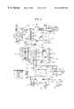
- FIG. 1shows a first embodiment of an interrogation apparatus
- FIG. 2shows a coherent demodulator
- FIG. 3is a circuit diagram of a multi-frequency data acquisition card
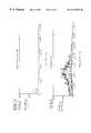
- FIG. 4shows a) the entire input PRBS and b) an expanded portion thereof
- FIG. 5shows the Fourier transform of the input PRBS of FIG. 4 a
- FIG. 6shows a) the entire output PRBS when a sensor is exposed to air and b) an expanded portion thereof;
- FIGS. 7 a and 7 bshow Fourier transform spectra of the output PRBS of FIG. 6 a;
- FIG. 8shows a) the entire output PRBS when a sensor is exposed to methanol vapour and b) an expanded portion thereof;
- FIGS. 9 a and 9 bshow Fourier transform spectra of the output PRBS of FIG. 8 a ;
- FIG. 10shows dissipation factors obtained when the sensor is exposed a) to air and b) to methanol vapour.
- FIGS. 1 and 2illustrate a method and apparatus for interrogating a sensor in which:
- said signalis coherently demodulated to obtain sensor responses at a plurality of frequencies.
- FIG. 1shows an interrogation system according to the invention for a gas sensor 12 comprising a PRBS generator 10 , a load resistor 14 and a coherent demodulator 16 .
- the systemfurther comprises a timing and control circuit 18 , data acquisition card 20 , power supply 22 and gas sampling system 24 .
- the power supply 22provides electrical power for the PRBS generator 10 , coherent demodulator 16 , timing and control circuit 18 , data acquisition card 20 and gas sampling system 24 .
- the timing and control circuit 18provides stable clock pulses for the PRBS generator 10 , and intermediate frequencies (defined below) for the coherent demodulator 16 via a crystal oscillator and programmable dividers (not shown).
- the circuit 18further provides control signals to control the gas sampling system 24 and data acquisition card 20 .
- the functions of the systemare i) to deduce the multifrequency sensor 12 response and ii) to monitor changes in this response on exposure of the sensor 12 to a gas.
- the gas sampling system 24permits such exposure of sensor 12 to a gas of interest, and allows purging of the sensor 12 and introduction of a reference gas (which may be the purging gas).
- the PRBS generator 10is a 4 bit parallel access shift register together with a quadruple 2-input exclusive—OR gate.
- the OR gategenerates the input signal to the shift register by the exclusive—OR combination of the third and fourth bit of the shift register, and thus the circuit goes through a maximum of 15 states.
- the PRBS generated therebyis applied to the sensor 12 , which may be of the type wherein a layer of semiconducting organic polymer such as polypyrrole is deposited on and between two metal electrodes so as to effect an electrical connection.
- FIG. 2A schematic diagram of the coherent demodulator (essentially a two channel cross correlation operator) is shown in FIG. 2 .
- the input 26the voltage across the load resistor 14 —is multiplied in one channel by sin (w i ) and in a second channel by cos (w i ) where w i is the radian frequency corresponding to cyclical frequency f i .
- These multiplication functionsare performed by a quadrature amplitude modulator based on a programmable four channel operational amplifier.
- the modulated signalsare low pass filtered by second order active low pass filters 28 , 30 , and added together with a summing operational amplifier 32 .
- the resulting output signal from the demodulator 16is sampled at the appropriate rate, converted into a digital signal and loaded into memory by the data acquisition card 20 . Data may be transferred therefrom into a computer for further processing and display.
- the demodulator 16may be used to obtain the system response at a chosen frequency, or a set of lines may be selected and the demodulation performed in parallel. It may be possible to derive further information from phase angle data.
- periodic signalsare the ease with which they may be recognised in the presence of noise and the substantially unbiased estimate of the system response—in this case the multifrequency response of the sensor—which they provide.
- a particularly preferred embodiment of such periodic signalsis a pseudorandom binary signal which, since its pulseform is deterministic, can be recreated as desired providing that the sequence start time and length are known.
- the frequencies of the PRBS sequenceare dictated by the gas sensor employed. Typically, frequencies in the range 0.1-1.0 MHz are required, but this range should not be considered a limiting one. Frequencies between ⁇ Hz to 100 MHz or greater may be routinely generated.
- the PRBSis preferably bipolar at voltage levels between ⁇ 0.1 to 1.0.V, but this should not be considered a limiting requirement either.
- FIG. 3is a circuit diagram of the card.
- PRBSis generated by a PRBS generator (not shown) and input to the card via PRBS inlet 34 and acquiring inlet 36 .
- the PRBS signalis at this stage in the form of 0-5V TTL signals.
- Circuitry 38converts this input signal into a bipolar PRBS code of magnitude ⁇ 0.25V. The use of bipolar signal is preferable since unipolar signal causes drift in sensor output.
- the computeralso supports software which controls the system variables.
- 16 shift register stagesare employed (tap point at the 4th stage) producing a sequence length of 65535 clock pulses.
- the ADC prescalerwas set to 20 MHz acquisition frequency and a PRBS prescaler value of 8 was employed (i.e. the shift frequency was 2.5 MHz and each data point corresponds to 0.4 ⁇ s).
- FIG. 4 ashows the total PRBS applied to the gas sensor. At this scale, such a representation is not very revealing.
- FIG. 4 bshows an expanded portion of the PRBS train.
- FIG. 5shows the spectrum obtained when a fast Fourier Transformation (FFT) is performed on the PRBS of FIG. 4 a by the computer. This is the frequency domain equivalent of the input to the sensor.
- the PRBSis intended to concentrate energy mainly in the region up to about 200 KHz.
- FIG. 6shows the output from the sensors, measured across the load resistor 46 , when the sensor is exposed to air (a gas sampling system similar to that described with regard to FIG. 1 is employed).
- FIG. 6 ashows the complete PRBS output—which, even at this level of resolution is clearly different from the input signal of FIG. 4 a —and
- FIG. 6 bshows an expanded portion.
- the delta-function like spikes of the PRBSare now somewhat distorted in appearance : this is undoubtedly due to the finite inductance and capacitance of the sensor.
- FIGS. 7 a and 7 bshow the frequency domain spectrum obtained by performing a FFT on the data of FIG. 6 a.
- FIGS. 8 a and 8 bshow the time domain output signal obtained when the sensor is exposed to methanol vapour.
- FIGS. 9 a and 9 bshow the corresponding frequency domain spectrum obtained when a FFT is performed on the output shown in FIG. 9 a .
- the spectrumis different to the spectrum obtained in air (FIG. 7 a ), showing that this interrogation technique can produce gas sensitive data.
- the absolute power of the frequency spectrum of FIG. 9 a , and the output signal amplitude of FIG. 8 aare smaller than the corresponding values obtained with air. This is consistent with the increase in dc resistance obtained when the sensor is exposed to methanol using the prior art dc resistance interrogation technique.
- FIGS. 10 and 10 bshow dissipation factors obtained, respectively, in air and methanol.
- the dissipation factoris obtained by dividing the real part of frequency response by the imaginary part of the response (plus an increment of 0.01 to prevent the occurence of a singularity).
- Distinctly different peak dissipation factorsare obtained, viz, ca. 60 KHz for air and ca. 150 KHz for methanol.
- ⁇ xy ( ⁇ )is the power spectral density function.
- Appropriate transformationssuch as a fast Fourier transform (FFT) may be applied for these purposes. It may be desirable to compute the auto-correlation function between the sensor output when exposed to unknown gas and the sensor output in the presence of an air reference flow. Covariance techniques may be applied as an alternative to cross correlation.
- the present inventionis not limited to semiconducting organic polymer based sensors, but rather, extends to any sensor which may be interrogated by application of multifrequency signals.
- sensorsinclude any material that can be treated as a dielectrical and which is affected by its environment, such as metal oxides, non-polymer semiconductors and organic polymers which are not semiconducting. Bulk acoustic wave and surface acoustic wave devices are also within the scope of the invention.
- gas sensingis of particular interest, it is possible to measure, using the methods and apparatus of the invention, the response of sensors to other influences, such as temperature and pressure, if they have any response thereto, either independently of or in conjunction with their possible response to the presence of a gas or mixture of gases.
- the use of semiconducting organic polymer based sensors in gas sensingincludes the detection of odours and volatile species, and, further, that such sensors may be employed in other applications, such as liquid phase analyte detection.
- the senorfor example as a smart tag which could be included in food packaging and scanned using electromagnetic radiation techniques to reveal its resonant frequency, which would be expected to change as the composition of gases changed within the packaging, which might reveal the age of the goods or some other factor such as whether the goods have been exposed to a temperature above the recommended storage temperature or if the package seal has failed.
- Such sensors with their associated circuitrycould be manufactured inexpensively and interrogated using a hand-portable scanning device for warehouse or supermarket use.
- the scanning devicecould comprise a database showing the expected response of various sensors—sensors used for meat products, for example, might be quite different and have a different characteristic response from sensors used for dairy products or packed vegetables.
- time to frequency domain transformation meanswould be very appropriate in the analysis of signals emitted by such smart tags in response to an interrogation signal, it may well be the case that the smart tags could incorporate some analytical circuitry that emitted—or failed to emit—a recognisable signal consequent upon some change in the sensor's environment, and such other analysis method could be used independently of or in conjunction with the time to frequency transformation based analysis of the present invention.
Landscapes
- Health & Medical Sciences (AREA)
- Life Sciences & Earth Sciences (AREA)
- Engineering & Computer Science (AREA)
- Chemical & Material Sciences (AREA)
- Physics & Mathematics (AREA)
- Pathology (AREA)
- General Health & Medical Sciences (AREA)
- Heart & Thoracic Surgery (AREA)
- Animal Behavior & Ethology (AREA)
- Biochemistry (AREA)
- Medicinal Chemistry (AREA)
- General Physics & Mathematics (AREA)
- Immunology (AREA)
- Food Science & Technology (AREA)
- Nuclear Medicine, Radiotherapy & Molecular Imaging (AREA)
- Radiology & Medical Imaging (AREA)
- Biophysics (AREA)
- Biomedical Technology (AREA)
- Combustion & Propulsion (AREA)
- Medical Informatics (AREA)
- Molecular Biology (AREA)
- Surgery (AREA)
- Analytical Chemistry (AREA)
- Public Health (AREA)
- Veterinary Medicine (AREA)
- Arrangements For Transmission Of Measured Signals (AREA)
- Investigating Or Analyzing Materials By The Use Of Fluid Adsorption Or Reactions (AREA)
- Investigating Or Analyzing Materials By The Use Of Electric Means (AREA)
- Surgical Instruments (AREA)
- Valve Device For Special Equipments (AREA)
- Measurement Of Mechanical Vibrations Or Ultrasonic Waves (AREA)
- Measurement Of Length, Angles, Or The Like Using Electric Or Magnetic Means (AREA)
- Transmission And Conversion Of Sensor Element Output (AREA)
- Measuring Pulse, Heart Rate, Blood Pressure Or Blood Flow (AREA)
- Burglar Alarm Systems (AREA)
- Measuring Fluid Pressure (AREA)
Abstract
Description


Claims (32)
Applications Claiming Priority (3)
| Application Number | Priority Date | Filing Date | Title |
|---|---|---|---|
| GB9523406 | 1995-11-16 | ||
| GBGB9523406.8AGB9523406D0 (en) | 1995-11-16 | 1995-11-16 | Sensor transduction |
| PCT/GB1996/002834WO1997018467A1 (en) | 1995-11-16 | 1996-11-18 | Sensor interrogation |
Publications (1)
| Publication Number | Publication Date |
|---|---|
| US6236951B1true US6236951B1 (en) | 2001-05-22 |
Family
ID=10783954
Family Applications (1)
| Application Number | Title | Priority Date | Filing Date |
|---|---|---|---|
| US09/068,830Expired - Fee RelatedUS6236951B1 (en) | 1995-11-16 | 1996-11-18 | Sensor interrogation |
Country Status (8)
| Country | Link |
|---|---|
| US (1) | US6236951B1 (en) |
| EP (1) | EP0861438B1 (en) |
| JP (1) | JP2000500861A (en) |
| AT (1) | ATE236396T1 (en) |
| AU (1) | AU7583496A (en) |
| DE (1) | DE69627175D1 (en) |
| GB (1) | GB9523406D0 (en) |
| WO (1) | WO1997018467A1 (en) |
Cited By (23)
| Publication number | Priority date | Publication date | Assignee | Title |
|---|---|---|---|---|
| US6575013B2 (en)* | 2001-02-26 | 2003-06-10 | Lucent Technologies Inc. | Electronic odor sensor |
| US20040006257A1 (en)* | 2002-03-04 | 2004-01-08 | Cyrano Sciences Inc. | Detection, diagnosis, and monitoring of a medical condition or disease with artificial olfactometry |
| US20040135684A1 (en)* | 2002-07-19 | 2004-07-15 | Cyrano Sciences Inc. | Non-specific sensor array detectors |
| WO2005122889A1 (en)* | 2004-06-18 | 2005-12-29 | Tallinn University Of Technology | Simultaneous discrete-time analysis of features of substances |
| WO2006027360A1 (en)* | 2004-09-06 | 2006-03-16 | Smartex S.R.L. | Device for the monitoring of physiologic variables through measurement of body electrical impedance |
| US7076389B1 (en)* | 2003-12-17 | 2006-07-11 | Sun Microsystems, Inc. | Method and apparatus for validating sensor operability in a computer system |
| US20080212100A1 (en)* | 2006-11-27 | 2008-09-04 | Nano-Proprietary, Inc. | Sono-Photonic Gas Sensor |
| US20100010459A1 (en)* | 2006-09-13 | 2010-01-14 | Francois Piette | Undergarment for incontinent person and treatment device connected to an undergarment |
| US20100170345A1 (en)* | 2007-09-19 | 2010-07-08 | Toppan Printin Co., Ltd. | Elastic wave measurement apparatus and method |
| US20130110061A1 (en)* | 2011-10-28 | 2013-05-02 | Kimberly-Clark Worldwide, Inc. | Electronic Discriminating Device for Body Exudate Detection |
| WO2014066704A1 (en) | 2012-10-24 | 2014-05-01 | Genmark Diagnostics, Inc. | Integrated multiplex target analysis |
| US8816149B2 (en) | 2011-10-28 | 2014-08-26 | Kimberly-Clark Worldwide, Inc. | System for detection and monitoring of body exudates using a gas emitting substance for use in interactive toilet training |
| US8933292B2 (en) | 2011-10-28 | 2015-01-13 | Kimberly-Clark Worldwide, Inc. | Absorbent article with sensor array for body exudate detection |
| US9222623B2 (en) | 2013-03-15 | 2015-12-29 | Genmark Diagnostics, Inc. | Devices and methods for manipulating deformable fluid vessels |
| WO2016077364A2 (en) | 2014-11-11 | 2016-05-19 | Genmark Diagnostics, Inc. | Instrument and cartridge for performing assays in a closed sample preparation and reaction system |
| WO2016077341A2 (en) | 2014-11-11 | 2016-05-19 | Genmark Diagnostics, Inc. | Instrument and cartridge for performing assays in a closed sample preparation and reaction system employing electrowetting fluid manipulation |
| US9498778B2 (en) | 2014-11-11 | 2016-11-22 | Genmark Diagnostics, Inc. | Instrument for processing cartridge for performing assays in a closed sample preparation and reaction system |
| US9598722B2 (en) | 2014-11-11 | 2017-03-21 | Genmark Diagnostics, Inc. | Cartridge for performing assays in a closed sample preparation and reaction system |
| WO2018053501A1 (en) | 2016-09-19 | 2018-03-22 | Genmark Diagnostics, Inc. | Instrument for processing cartridge for performing assays in a closed sample preparation and reaction system |
| US10106847B1 (en) | 2017-08-24 | 2018-10-23 | Clinical Micro Sensors, Inc. | Electrochemical detection of bacterial and/or fungal infections |
| WO2019040769A1 (en) | 2017-08-24 | 2019-02-28 | Clinical Micro Sensors, Inc. (dba GenMark Diagnostics, Inc.) | Electrochemical detection of bacterial and/or fungal infections |
| US10495656B2 (en) | 2012-10-24 | 2019-12-03 | Genmark Diagnostics, Inc. | Integrated multiplex target analysis |
| USD881409S1 (en) | 2013-10-24 | 2020-04-14 | Genmark Diagnostics, Inc. | Biochip cartridge |
Families Citing this family (2)
| Publication number | Priority date | Publication date | Assignee | Title |
|---|---|---|---|---|
| GB9908696D0 (en)* | 1999-04-17 | 1999-06-09 | Chandler Robert W | High impedance sensor apparatus and method for detecting fluids |
| GB0522888D0 (en)* | 2005-11-10 | 2005-12-21 | Univ Southampton | Measurement of the electrical impedance frequency spectrum |
Citations (9)
| Publication number | Priority date | Publication date | Assignee | Title |
|---|---|---|---|---|
| US3691364A (en) | 1969-03-20 | 1972-09-12 | Okura Denki Co Ltd | Continuous analyzing device |
| GB2203553A (en) | 1987-04-06 | 1988-10-19 | Cogent Ltd | Gas sensor |
| EP0387100A2 (en) | 1989-03-10 | 1990-09-12 | Hitachi, Ltd. | Ignition timing control method for an internal combustion engine and apparatus therefor |
| US5045285A (en)* | 1989-09-05 | 1991-09-03 | United States Of America As Represented By The Secretary Of The Air Force | Gaseous component identification with polymeric film sensor |
| JPH05296908A (en) | 1992-04-17 | 1993-11-12 | Yokogawa Electric Corp | Gas sensor |
| US5610908A (en)* | 1992-09-07 | 1997-03-11 | British Broadcasting Corporation | Digital signal transmission system using frequency division multiplex |
| US5614834A (en)* | 1995-03-15 | 1997-03-25 | The United States Of America As Represented By The Secretary Of The Air Force | Sampling receivers |
| US5870405A (en)* | 1992-11-30 | 1999-02-09 | Digital Voice Systems, Inc. | Digital transmission of acoustic signals over a noisy communication channel |
| US5918257A (en)* | 1993-09-17 | 1999-06-29 | Alpha M.O.S. | Methods and devices for the detection of odorous substances and applications |
- 1995
- 1995-11-16GBGBGB9523406.8Apatent/GB9523406D0/enactivePending
- 1996
- 1996-11-18JPJP9518689Apatent/JP2000500861A/enactivePending
- 1996-11-18ATAT96938387Tpatent/ATE236396T1/ennot_activeIP Right Cessation
- 1996-11-18EPEP96938387Apatent/EP0861438B1/ennot_activeExpired - Lifetime
- 1996-11-18WOPCT/GB1996/002834patent/WO1997018467A1/enactiveIP Right Grant
- 1996-11-18DEDE69627175Tpatent/DE69627175D1/ennot_activeExpired - Lifetime
- 1996-11-18USUS09/068,830patent/US6236951B1/ennot_activeExpired - Fee Related
- 1996-11-18AUAU75834/96Apatent/AU7583496A/ennot_activeAbandoned
Patent Citations (9)
| Publication number | Priority date | Publication date | Assignee | Title |
|---|---|---|---|---|
| US3691364A (en) | 1969-03-20 | 1972-09-12 | Okura Denki Co Ltd | Continuous analyzing device |
| GB2203553A (en) | 1987-04-06 | 1988-10-19 | Cogent Ltd | Gas sensor |
| EP0387100A2 (en) | 1989-03-10 | 1990-09-12 | Hitachi, Ltd. | Ignition timing control method for an internal combustion engine and apparatus therefor |
| US5045285A (en)* | 1989-09-05 | 1991-09-03 | United States Of America As Represented By The Secretary Of The Air Force | Gaseous component identification with polymeric film sensor |
| JPH05296908A (en) | 1992-04-17 | 1993-11-12 | Yokogawa Electric Corp | Gas sensor |
| US5610908A (en)* | 1992-09-07 | 1997-03-11 | British Broadcasting Corporation | Digital signal transmission system using frequency division multiplex |
| US5870405A (en)* | 1992-11-30 | 1999-02-09 | Digital Voice Systems, Inc. | Digital transmission of acoustic signals over a noisy communication channel |
| US5918257A (en)* | 1993-09-17 | 1999-06-29 | Alpha M.O.S. | Methods and devices for the detection of odorous substances and applications |
| US5614834A (en)* | 1995-03-15 | 1997-03-25 | The United States Of America As Represented By The Secretary Of The Air Force | Sampling receivers |
Non-Patent Citations (3)
| Title |
|---|
| Ding et al. "A New Golay Code System for Ultrasonic Pulse Echo Measurements", Meas. Sci. Technol. 1, 1990, pp 158-165. |
| Persaud et al., "Design Strategies for Gas and Odour Sensors Which Mimic the Olfactory System", Robots and Biological Systems: vol. 102, 1993, pp 579-602. |
| Z X Ding and P A Payne, "A New Golay Code System for Ultrasonic Pulse Echo Measurements", Meas. Sci. Technol. 1 (1990), pp. 158-165, 1990.* |
Cited By (53)
| Publication number | Priority date | Publication date | Assignee | Title |
|---|---|---|---|---|
| US6575013B2 (en)* | 2001-02-26 | 2003-06-10 | Lucent Technologies Inc. | Electronic odor sensor |
| US7819803B2 (en) | 2002-03-04 | 2010-10-26 | Smiths Detection Inc. | Detection, diagnosis, and monitoring of a medical condition or disease with artificial olfactometry |
| US7255677B2 (en) | 2002-03-04 | 2007-08-14 | Smiths Detection Inc. | Detection, diagnosis, and monitoring of a medical condition or disease with artificial olfactometry |
| US20040006257A1 (en)* | 2002-03-04 | 2004-01-08 | Cyrano Sciences Inc. | Detection, diagnosis, and monitoring of a medical condition or disease with artificial olfactometry |
| US20070265509A1 (en)* | 2002-03-04 | 2007-11-15 | Smiths Detection Inc. | Detection, diagnosis, and monitoring of a medical condition or disease with artificial olfactometry |
| US20040135684A1 (en)* | 2002-07-19 | 2004-07-15 | Cyrano Sciences Inc. | Non-specific sensor array detectors |
| US7034677B2 (en) | 2002-07-19 | 2006-04-25 | Smiths Detection Inc. | Non-specific sensor array detectors |
| US7076389B1 (en)* | 2003-12-17 | 2006-07-11 | Sun Microsystems, Inc. | Method and apparatus for validating sensor operability in a computer system |
| WO2005122889A1 (en)* | 2004-06-18 | 2005-12-29 | Tallinn University Of Technology | Simultaneous discrete-time analysis of features of substances |
| US20080275361A1 (en)* | 2004-09-06 | 2008-11-06 | Smartex S.R.L. | Device for the Monitoring of Physiologic Variables Through Measurement of Body Electrical Impedance |
| WO2006027360A1 (en)* | 2004-09-06 | 2006-03-16 | Smartex S.R.L. | Device for the monitoring of physiologic variables through measurement of body electrical impedance |
| US7869866B2 (en) | 2004-09-06 | 2011-01-11 | Smartex S.R.L. | Device for the monitoring of physiologic variables through measurement of body electrical impedance |
| US8394074B2 (en)* | 2006-09-13 | 2013-03-12 | Universite Pierre Et Marie Curie (Paris 6) | Undergarment for incontinent person and treatment device connected to an undergarment |
| US20100010459A1 (en)* | 2006-09-13 | 2010-01-14 | Francois Piette | Undergarment for incontinent person and treatment device connected to an undergarment |
| US20080212100A1 (en)* | 2006-11-27 | 2008-09-04 | Nano-Proprietary, Inc. | Sono-Photonic Gas Sensor |
| US7782462B2 (en) | 2006-11-27 | 2010-08-24 | Applied Nanotech Holdings, Inc. | Sono-photonic gas sensor |
| US20100170345A1 (en)* | 2007-09-19 | 2010-07-08 | Toppan Printin Co., Ltd. | Elastic wave measurement apparatus and method |
| US8413516B2 (en) | 2007-09-19 | 2013-04-09 | Toppan Printing Co., Ltd. | Elastic wave measurement apparatus and method |
| US8816149B2 (en) | 2011-10-28 | 2014-08-26 | Kimberly-Clark Worldwide, Inc. | System for detection and monitoring of body exudates using a gas emitting substance for use in interactive toilet training |
| US20130110061A1 (en)* | 2011-10-28 | 2013-05-02 | Kimberly-Clark Worldwide, Inc. | Electronic Discriminating Device for Body Exudate Detection |
| US8933292B2 (en) | 2011-10-28 | 2015-01-13 | Kimberly-Clark Worldwide, Inc. | Absorbent article with sensor array for body exudate detection |
| US9119748B2 (en)* | 2011-10-28 | 2015-09-01 | Kimberly-Clark Worldwide, Inc. | Electronic discriminating device for body exudate detection |
| WO2014066704A1 (en) | 2012-10-24 | 2014-05-01 | Genmark Diagnostics, Inc. | Integrated multiplex target analysis |
| US11952618B2 (en) | 2012-10-24 | 2024-04-09 | Roche Molecular Systems, Inc. | Integrated multiplex target analysis |
| EP2965817A1 (en) | 2012-10-24 | 2016-01-13 | Genmark Diagnostics Inc. | Integrated multiplex target analysis |
| EP3919174A2 (en) | 2012-10-24 | 2021-12-08 | Genmark Diagnostics Inc. | Integrated multiplex target analysis |
| USD900330S1 (en) | 2012-10-24 | 2020-10-27 | Genmark Diagnostics, Inc. | Instrument |
| US10495656B2 (en) | 2012-10-24 | 2019-12-03 | Genmark Diagnostics, Inc. | Integrated multiplex target analysis |
| US9957553B2 (en) | 2012-10-24 | 2018-05-01 | Genmark Diagnostics, Inc. | Integrated multiplex target analysis |
| EP3427830A1 (en) | 2012-10-24 | 2019-01-16 | Genmark Diagnostics Inc. | Integrated multiplex target analysis |
| US10391489B2 (en) | 2013-03-15 | 2019-08-27 | Genmark Diagnostics, Inc. | Apparatus and methods for manipulating deformable fluid vessels |
| US9453613B2 (en) | 2013-03-15 | 2016-09-27 | Genmark Diagnostics, Inc. | Apparatus, devices, and methods for manipulating deformable fluid vessels |
| US10807090B2 (en) | 2013-03-15 | 2020-10-20 | Genmark Diagnostics, Inc. | Apparatus, devices, and methods for manipulating deformable fluid vessels |
| US9222623B2 (en) | 2013-03-15 | 2015-12-29 | Genmark Diagnostics, Inc. | Devices and methods for manipulating deformable fluid vessels |
| US9410663B2 (en) | 2013-03-15 | 2016-08-09 | Genmark Diagnostics, Inc. | Apparatus and methods for manipulating deformable fluid vessels |
| USD881409S1 (en) | 2013-10-24 | 2020-04-14 | Genmark Diagnostics, Inc. | Biochip cartridge |
| US9498778B2 (en) | 2014-11-11 | 2016-11-22 | Genmark Diagnostics, Inc. | Instrument for processing cartridge for performing assays in a closed sample preparation and reaction system |
| WO2016077364A2 (en) | 2014-11-11 | 2016-05-19 | Genmark Diagnostics, Inc. | Instrument and cartridge for performing assays in a closed sample preparation and reaction system |
| EP4578539A2 (en) | 2014-11-11 | 2025-07-02 | Roche Diagnostics GmbH | Instrument and cartridge for performing assays in a closed sample preparation and reaction system |
| US10005080B2 (en) | 2014-11-11 | 2018-06-26 | Genmark Diagnostics, Inc. | Instrument and cartridge for performing assays in a closed sample preparation and reaction system employing electrowetting fluid manipulation |
| US9598722B2 (en) | 2014-11-11 | 2017-03-21 | Genmark Diagnostics, Inc. | Cartridge for performing assays in a closed sample preparation and reaction system |
| WO2016077341A2 (en) | 2014-11-11 | 2016-05-19 | Genmark Diagnostics, Inc. | Instrument and cartridge for performing assays in a closed sample preparation and reaction system employing electrowetting fluid manipulation |
| US10864522B2 (en) | 2014-11-11 | 2020-12-15 | Genmark Diagnostics, Inc. | Processing cartridge and method for detecting a pathogen in a sample |
| EP3831481A1 (en) | 2014-11-11 | 2021-06-09 | Genmark Diagnostics Inc. | Instrument and cartridge for performing assays in a closed sample preparation and reaction system |
| US12000847B2 (en) | 2016-09-19 | 2024-06-04 | Roche Molecular Systems, Inc. | Instrument for processing cartridge for performing assays in a closed sample preparation and reaction system |
| WO2018053501A1 (en) | 2016-09-19 | 2018-03-22 | Genmark Diagnostics, Inc. | Instrument for processing cartridge for performing assays in a closed sample preparation and reaction system |
| US11300578B2 (en) | 2016-09-19 | 2022-04-12 | Roche Molecular Systems, Inc. | Instrument for processing cartridge for performing assays in a closed sample preparation and reaction system |
| WO2019040769A1 (en) | 2017-08-24 | 2019-02-28 | Clinical Micro Sensors, Inc. (dba GenMark Diagnostics, Inc.) | Electrochemical detection of bacterial and/or fungal infections |
| US11021759B2 (en) | 2017-08-24 | 2021-06-01 | Clinical Micro Sensors, Inc. | Electrochemical detection of bacterial and/or fungal infections |
| US10669592B2 (en) | 2017-08-24 | 2020-06-02 | Clinical Micro Sensors, Inc. | Electrochemical detection of bacterial and/or fungal infections |
| US10273535B2 (en) | 2017-08-24 | 2019-04-30 | Clinical Micro Sensors, Inc. | Electrochemical detection of bacterial and/or fungal infections |
| EP4549590A2 (en) | 2017-08-24 | 2025-05-07 | Roche Diagnostics GmbH | Electrochemical detection of bacterial and/or fungal infections |
| US10106847B1 (en) | 2017-08-24 | 2018-10-23 | Clinical Micro Sensors, Inc. | Electrochemical detection of bacterial and/or fungal infections |
Also Published As
| Publication number | Publication date |
|---|---|
| DE69627175D1 (en) | 2003-05-08 |
| AU7583496A (en) | 1997-06-05 |
| ATE236396T1 (en) | 2003-04-15 |
| EP0861438B1 (en) | 2003-04-02 |
| WO1997018467A1 (en) | 1997-05-22 |
| EP0861438A1 (en) | 1998-09-02 |
| GB9523406D0 (en) | 1996-01-17 |
| JP2000500861A (en) | 2000-01-25 |
Similar Documents
| Publication | Publication Date | Title |
|---|---|---|
| US6236951B1 (en) | Sensor interrogation | |
| US6356350B1 (en) | Wavelength modulation spectroscopy with multiple harmonic detection | |
| US7239155B2 (en) | Electrochemical impedance measurement system and method for use thereof | |
| US5343147A (en) | Method and apparatus for using stochastic excitation and a superconducting quantum interference device (SAUID) to perform wideband frequency response measurements | |
| CN105911530B (en) | FMCW radar system | |
| US8676543B2 (en) | Determining the resonance parameters for mechanical oscillators | |
| US9201048B2 (en) | Systems for characterizing resonance behavior of magnetostrictive resonators | |
| JP2002528724A5 (en) | ||
| US6688159B1 (en) | Method and device for determining the gas concentrations in a gas mixture | |
| Amrani et al. | Pseudo-random binary sequence interrogation technique for gas sensors | |
| EP0001919A1 (en) | Identification of materials using their complex dielectric response | |
| Wen et al. | Detecting and evaluating the signals of wirelessly interrogational passive SAW resonator sensors | |
| US20250291085A1 (en) | Asynchronous method for sampling signals in metal detectors | |
| Borkowski | LIDFT-the DFT linear interpolation method | |
| EP0895595B1 (en) | Apparatus and method for detecting fluids | |
| Parvis et al. | A precompliance EMC test-set based on a sampling oscilloscope | |
| Khoshakhlagh et al. | A pigeonhole principle-based method for estimating the resonant frequency of SAWR sensors | |
| Carli et al. | A smart low-cost QCM-D based on lightweight frequency domain processing | |
| RU2051476C1 (en) | Method of and device for plasma diagnostics | |
| Fort et al. | Enhancing QCM-D Sensitivity for Biosensing Applications through Novel Transient Signal Processing | |
| GB2305248A (en) | Induction well logging instruments | |
| Dai et al. | A novel instrument based upon extremely high Q-value surface acoustic wave resonator array and neural network | |
| Sirkis et al. | Extended range pseudo-heterodyne demodulation for fiber optic sensors | |
| Manstein et al. | A device for shallow frequency-domain electromagnetic induction sounding | |
| Bretthorst | Estimating the ratio of two amplitudes in nuclear magnetic resonance data |
Legal Events
| Date | Code | Title | Description |
|---|---|---|---|
| AS | Assignment | Owner name:AROMASCAN PLC, GREAT BRITAIN Free format text:ASSIGNMENT OF ASSIGNORS INTEREST;ASSIGNORS:PAYNE, PETER ALFRED;PERSAUD, KRISHNA CHANDRA;AMRANI, MOHAMMED EL HASSAN;REEL/FRAME:009374/0151;SIGNING DATES FROM 19980414 TO 19980416 | |
| AS | Assignment | Owner name:OSMETECH PLC, GREAT BRITAIN Free format text:CHANGE OF NAME;ASSIGNOR:AROMASCAN PLC;REEL/FRAME:010579/0050 Effective date:19990614 | |
| AS | Assignment | Owner name:OSMETECH PLC, GREAT BRITAIN Free format text:CHANGE OF NAME;ASSIGNOR:AROMASCAN PLC;REEL/FRAME:010547/0187 Effective date:19990614 | |
| CC | Certificate of correction | ||
| REMI | Maintenance fee reminder mailed | ||
| LAPS | Lapse for failure to pay maintenance fees | ||
| STCH | Information on status: patent discontinuation | Free format text:PATENT EXPIRED DUE TO NONPAYMENT OF MAINTENANCE FEES UNDER 37 CFR 1.362 | |
| FP | Lapsed due to failure to pay maintenance fee | Effective date:20050522 | |
| AS | Assignment | Owner name:GENMARK DIAGNOSTICS, INC., CALIFORNIA Free format text:ASSIGNMENT OF ASSIGNORS INTEREST;ASSIGNOR:OSMETECH PLC;REEL/FRAME:025026/0788 Effective date:20100831 |