US6236717B1 - Simultaneous voice/data answering machine - Google Patents
Simultaneous voice/data answering machineDownload PDFInfo
- Publication number
- US6236717B1 US6236717B1US09/002,637US263798AUS6236717B1US 6236717 B1US6236717 B1US 6236717B1US 263798 AUS263798 AUS 263798AUS 6236717 B1US6236717 B1US 6236717B1
- Authority
- US
- United States
- Prior art keywords
- message
- data
- audio
- voice
- signal
- Prior art date
- Legal status (The legal status is an assumption and is not a legal conclusion. Google has not performed a legal analysis and makes no representation as to the accuracy of the status listed.)
- Expired - Lifetime
Links
- 238000000034methodMethods0.000claimsdescription23
- 230000005236sound signalEffects0.000claimsdescription4
- 230000008878couplingEffects0.000claims4
- 238000010168coupling processMethods0.000claims4
- 238000005859coupling reactionMethods0.000claims4
- 230000005540biological transmissionEffects0.000description19
- 238000010586diagramMethods0.000description10
- 230000006870functionEffects0.000description7
- 238000001514detection methodMethods0.000description6
- 230000011664signalingEffects0.000description4
- OKTJSMMVPCPJKN-UHFFFAOYSA-NCarbonChemical compound[C]OKTJSMMVPCPJKN-UHFFFAOYSA-N0.000description1
- 230000003139buffering effectEffects0.000description1
- 238000009924canningMethods0.000description1
- 229910052799carbonInorganic materials0.000description1
- 238000006243chemical reactionMethods0.000description1
- 238000013500data storageMethods0.000description1
- 230000009977dual effectEffects0.000description1
- 230000000694effectsEffects0.000description1
- 230000004044responseEffects0.000description1
- 230000002123temporal effectEffects0.000description1
Images


Classifications
- H—ELECTRICITY
- H04—ELECTRIC COMMUNICATION TECHNIQUE
- H04M—TELEPHONIC COMMUNICATION
- H04M1/00—Substation equipment, e.g. for use by subscribers
- H04M1/64—Automatic arrangements for answering calls; Automatic arrangements for recording messages for absent subscribers; Arrangements for recording conversations
- H04M1/65—Recording arrangements for recording a message from the calling party
- H04M1/652—Means for playing back the recorded messages by remote control over a telephone line
- H—ELECTRICITY
- H04—ELECTRIC COMMUNICATION TECHNIQUE
- H04M—TELEPHONIC COMMUNICATION
- H04M1/00—Substation equipment, e.g. for use by subscribers
- H04M1/64—Automatic arrangements for answering calls; Automatic arrangements for recording messages for absent subscribers; Arrangements for recording conversations
- H04M1/65—Recording arrangements for recording a message from the calling party
- H04M1/6505—Recording arrangements for recording a message from the calling party storing speech in digital form
- H—ELECTRICITY
- H04—ELECTRIC COMMUNICATION TECHNIQUE
- H04M—TELEPHONIC COMMUNICATION
- H04M3/00—Automatic or semi-automatic exchanges
- H04M3/42—Systems providing special services or facilities to subscribers
- H04M3/50—Centralised arrangements for answering calls; Centralised arrangements for recording messages for absent or busy subscribers ; Centralised arrangements for recording messages
- H04M3/53—Centralised arrangements for recording incoming messages, i.e. mailbox systems
- H04M3/5307—Centralised arrangements for recording incoming messages, i.e. mailbox systems for recording messages comprising any combination of audio and non-audio components
Definitions
- the term “media”refers to the type of information conveyed in a message.
- a usercan “listen” to a message recorded on a telephone answering machine. This represents an audio form of messaging, i.e., an “audio media.”
- a usercan “see” a message on the display of a computer, e.g., “electronic mail” (e-mail), which in simple form is simply a data message comprising alpha-numeric characters, i.e., a “video media.”.
- electronic mailelectronic mail
- a multimedia messageincludes an audio message and an associated data message, with the result that while the user is listening to the audio message, the user is also viewing the associated data message.
- a simultaneous voice and data (SVD) modemcoordinates the storage of voice messages and data messages on an audio answering machine and a computer, respectively. This allows the called party to subsequently retrieve, via the SVD modem, both a voice message and an associated data message, i.e., a multimedia message, where the called party listens to the voice message while viewing the associated data message.
- the called partycan retrieve the multimedia message either locally or from a remote location.
- FIG. 1shows a block diagram of a simultaneous voice and data communications system embodying the principles of the invention
- FIG. 2shows a block diagram of a simultaneous voice and data modern embodying the principles of the invention
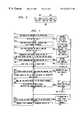
- FIG. 3is a table showing illustrative SVD identification signal assignments
- FIG. 4is an illustrative SVD symbol block that provides a secondary communications channel
- FIG. 5illustrative flow diagram of a method embodying the principles of the invention for recording a multimedia message
- FIG. 6shows an illustrative multimedia message header
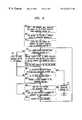
- FIG. 7is an illustrative flow diagram of a method embodying the principles of the invention for remotelyretrieving a multimedia message
- FIG. 8is an illustrative flow diagram of a method embodying the principles of the invention for locally retrieving a multimedia message.
- FIG. 9shows another block diagram of a simultaneous voice and data communications system embodying the principles of the invention.
- FIG. 1A block diagram of a simultaneous voice and data communications system embodying the principles of the invention is shown in FIG. 1 .
- the equipment of user 1includes data terminal equipment (DTE) 10 , telephone 20 , answering machine 25 , and SVD modem 100 .
- DTE 10is coupled to SVD modem 100 via line 11 .
- Telephone 20is coupled via line 19 to answering machine 25 , which is coupled to SVD modem 100 via line 21 . It is assumed that lines 19 and 21 represent a “tip/ring” type of electrical interface.
- SVD modem 100is coupled to public switched telephone network (PSTN) 500 , via local loop 101 , for originating and answering telephone calls.
- Local loop 101is a typical “tip/ring” facility, i.e., a wire-pair, upon which a voice-band signal is transmitted between SVD modem 100 and PSTN 500 .
- the equipment of the remaining usersis similar.
- the equipment of user 2includes DTE 60 and telephone 50 , both of which are coupled to SVD modem 200 via lines 61 and 51 , respectively.
- SVD modem 200is coupled to PSTN 500 via local loop 201 .
- the equipment of user 1 -(remote)includes DTE 30 and telephone 40 , both of which are coupled to SVD modem 300 via lines 31 and 41 , respectively.
- Local loop 301couples SVD modem 300 to PSTN 500 .
- FIG. 2shows an illustrative block diagram of SVD modem 100 .
- CPU 125is a microprocessor-based central processing unit, memory, and associated circuitry for controlling SVD modem 100 .
- SVD modem 100operates in either a “voice-only” mode, a “data-only” mode, or an SVD mode.
- the “voice-only” modesimply communicates a signal, e.g., a voice signal, present on one analog port to the other.
- the “data-only” modemodulates a data signal received via DTE port 115 for transmission via PSTN port 110 to a remote data endpoint, and demodulates a modulated data signal received via PSTN port 110 for transmission to DTE 10 .
- the SVD modeprovides the combination of the “voice-only” and “data-only” mode with the exception that the signal received and transmitted via PSTN port 110 is a combined voice and data signal (hereafter referred to as an “SVD signal”).
- CPU 125of SVD modem 100 , controls switch 160 , via line 126 , as a function of the type of the operating mode of SVD modem 100 .
- switch 160couples any signal on line 162 to line 166 for transmission via telephone port 105 , and couples any signal on line 149 to line 161 for transmission via PSTN port 110 .
- the remaining componentse.g., data encoder 155 , data decoder 140 , voice decoder 130 , and voice encoder 150 , are disabled by control signals (not shown) from CPU 125 . Consequently, in the “voice-only” mode any analog signal appearing at one of the PSTN ports is coupled, or bridged, to the other PSTN port.
- switch 160couples any signal on line 146 to line 161 for transmission via PSTN port 110 , and couples any signal on line 162 to line 131 .
- voice encoder 150 and voice decoder 130are disabled by control signals (not shown) from CPU 125 .
- any data signal appearing at DTE port 115(assuming SVD modem 100 is not receiving “AT commands”) is encoded by data encoder 155 .
- DTE port 115is assumed to represent an Electronic Industry Association (EIA) RS-232 interface.
- EIAElectronic Industry Association
- Data encoder 155includes any of the well-known encoding techniques like scrambling, trellis-coding, etc., to provide a sequence of symbols on line 156 at a symbol rate, 1 IT to modulator 145 .
- the symbolsare selected from a two-dimensional signal space (not shown).
- voice encoder 150is disabled, adder 165 does not add a signal to the output signal from data encoder 155 .
- Modulator 145illustratively provides a quadrature amplitude modulated signal (QAM) to PSTN port 110 via switch 160 .
- QAMquadrature amplitude modulated signal
- a QAM signal received at PSTN port 110is provided to demodulator 135 via switch 160 .
- Demodulator 135provides an encoded data stream to data decoder 140 . The latter performs the inverse function of data encoder 155 and provides a received data signal to DTE port 115 for transmission to DTE 10 .
- switch 160couples any signal on line 146 to line 161 for transmission via PSTN port 110 , and couples any signal on line 162 to line 131 .
- voice encoder 150 and voice decoder 130are enabled by control signals (not shown) from CPU 125 .
- any analog signale.g., a voice signal, appearing on line 149 is applied to voice encoder 150 .
- the latterprocesses the voice signal so that it is mapped into the two-dimensional signal space used by data encoder 155 to provide a voice signal point. This voice signal point defines the magnitude and angle of a “voice signal vector” about the origin of the two-dimensional signal space.
- Voice encoder 150provides a sequence of two-dimensional signal points, at the predefined symbol rate of I/T symbols per sec., on line 151 .
- Adder 165adds each voice signal vector on line 151 , if any, to a respective one of the symbols provided by data encoder 155 to provide a stream of signal points to modulator 145 .
- modulator 145provides a QAM modulated signal to PSTN port 110 via switch 160 .
- This QAM modulated signalis the above-mentioned SVD signal since it represents both voice and data.
- the received SVD signal on line 131is processed as described above by demodulator 135 and data decoder 140 to provide the received data signal on line 127 .
- voice decoder 130receives both the received signal Point sequence from demodulator 135 and the decoded symbol sequence from data decoder 140 .
- Voice decoder 130includes suitable buffering to allow for the decoding time needed by data decoder 140 to make a decision as to a received symbol.
- Voice decoder 130subtracts the received symbol provided by data decoder 140 from the respective received signal point provided by demodulator 135 to yield the voice signal vector and then performs the inverse function of voice encoder 150 to provide a received voice signal to telephone port 105 , via line 133 .
- this SVD techniqueadvantageously provides a voice-band signal that has both an audio portion and a data portion. This allows two users with simultaneous voice and data capable modems to communicate data between them and talk at the same time—yet only requires one “tip/ring” type telephone line at each user's location.
- the calling SVD modemDuring the establishment of an SVD connection it is advantageous for the calling SVD modem to initially signal the far-end, or called, SVD modem, that the calling modem is also an SVD modem.
- This initial signalingis accomplished by the use of an SVD identification signal that is transmitted by the calling SVD modem after dialing the telephone number of the called SVD modem.
- This type of notificationallows the answering SVD modem to immediately switch to an SVD mode as opposed to initially defaulting to a standard data modulation like CCITT′ V.32 and then switching to an SVD mode.
- An illustrative set of distinctive identification signals for use by an SVD modemis shown in FIG. 2 .
- These handshaking signalsinclude a calling signal, SVD CNG, which include calling tones “a” and “b,” and an answer identification signal, SVD AID, which includes answering tones “a” and “b.”
- the called SVD modemprovides the answer identification signal as an acknowledgment to the calling SVD modem that the call has been answered by an SVD compatible modem.
- the determination of what mode SVD modem 100 is independs upon whether SVD modem 100 is originating or answering a telephone call. If SVD modem 100 is originating a telephone call, then the calling party, e.g., user 1 , can select the particular mode of operation in a number of ways. One illustrative way is simply via a command mode instruction provided via DTE port 115 . Another way is for SVD modem 100 to evaluate the state of various signals at both telephone port 105 and DTE port 115 . For example, “voice-only” mode is entered if an “off-hook” signal is detected at telephone port 105 and there is no data-terminal-ready (DTR) 5 signal from DTE 10 . Conversely, “data-only” mode is entered if there is no “offhook” signal but the DTR signal is active.
- DTRdata-terminal-ready
- SVD modem 100When user 1 is the called party, i.e., when SVD modem 100 answers an incoming telephone call, the determination of what operating mode to enter is performed as follows. SVD modem 100 first determines if an SVD identification signal is being transmitted by the calling party's equipment. If SVD modem 100 detects an SVD identification signal, then the SVD mode of operation is entered. However, if no SVD identification signal is detected, SVD modem 100 can either enter the “voice-only” mode or the “data-only” mode. The particular selection is set by user 1 via a command mode instruction provided via DTE port 115 . This command mode instruction sets a “default” mode of operation for SVD modem 100 if no SVD identification signal is detected from the calling party's equipment.
- a secondary channelthat communicates signaling information between, e.g., SVD modem 100 and SVD modem 200 , and can be implemented in any number of ways.
- a secondary channelcan be provided by multiplexing the data modulated signal (here the SVD signal) with another control signal; or a secondary channel can be provided as described in the co-pending, commonly assigned, U.S. patent application of Bremer et al. entitled “Side-Channel Communications in Simultaneous Voice and Data Transmission,” serial No.
- FIG. 4shows a diagram of a transmission scheme that includes a side-channel within an SVD signal.
- This SVD side-channelnot only provides for the transport of additional information between any SVD endpoints—but also allows the voice signal to be transmitted across the full bandwidth of the SVD data connection.
- information from an SVD modemis provided in a frame, or “symbol block,” e.g., symbol block 405 .
- symbol blockcomprises 70 symbols. Consecutive symbols within each symbol block are identified as S 1 , S 2 , S 3 , . . . , S 70 .
- Each symbol blockis further divided into a data segment, e.g., data segment 406 ; and a control segment, e.g., control segment 407 .
- a data segmente.g., data segment 406
- a control segmente.g., control segment 407
- the group of symbols in the data segmentbe SI to S 56 .
- the symbol rateis illustratively 3000 symbols/second (s/sec.), although other symbol rates may be used, e.g., 2800 s/sec.
- the resultant data rateis 14400 bits/sec (bps). It is assumed that this data rate is high enough to meet a user's needs so that the remaining bandwidth of the SVD data connection can be allocated to the control segment, which provides the side-channel.
- control symbolsThe remaining symbols of the control segment, i.e., S 57 to S 70 , are the “control symbols.” Usually, the latter never convey DTE data, but convey control information.
- Each control symbolrepresents a number of “control bits.” For example, some of these control bits represent a state identifier, which provides information to the far-end, or receiving, SVD modem as to the mode of operation of the transmitting SVD modem, i.e., whether the transmitting SVD modem is in the “voice-only” mode, “data-only” mode, or SVD mode, of operation.
- the control symbolsare encoded and scrambled the same as the DTE data symbols, e.g., they use the same signal space.
- the control symbolsprovide the side-channel for conveying additional signaling information between SVD modem endpoints.
- the data symbolsrepresent user data and the control symbols represent control information, both the data and control symbols may also convey analog data, which in this example is any voice signal that is provided to SVD modem 100 by telephone 20 .
- the side-channelis a part of the simultaneous voice and data transmission.
- DTE 10is a personal computer that is powered up and running a software program that enables remote access via line I 1 .
- Examples of this type of remote access softwareinclude, “Carbon Copy” from Microcom, Inc., “Close-up” from Norton-Lambert, and “PC Anywhere” from Symantec.
- This remote accessallows any user, e.g., user 2 , to run application software on DTE 10 “remotely.”
- answering machine 25is any currently available answering machine that supports remote access with well-known features like “pause,” etc.
- FIG. 2it is assumed that SVD modem 100 receives a telephone call from user 2 .
- FIG. 5represents an illustrative method used herein to record a multimedia message.
- CPU 125 of SVD modem 100answers a telephone call that user 2 originates.
- CPU 125determines in step 610 whether or not the incoming telephone call is an SVD call by detecting the SVD identification signal, via line 134 from demodulator 135 , in step 610 . If no SVD identification signal is detected, CPU 125 provides “voice-only,” or “data-only,” call handling as described earlier. If the incoming call is a voice call, then CPU 125 “rings,” or alerts, the voice terminal equipment coupled to line 21 (ringing circuitry, which is well known in the art, is not shown in FIG. 2 ).
- answering machine 25subsequently answers the telephone call after the prescribed number of rings and allows the calling party to leave a message.
- the incoming callis a data call, user 2 remotely accesses DTE 10 .
- CPU 125switches to the SVD mode of operation and, in step 620 , “rings,” or alerts, any voice terminal equipment and the data terminal equipment coupled to lines 21 and I 1 , respectively. If both the voice terminal equipment coupled to line 21 and the data terminal equipment coupled to line 11 answer, then CPU 125 goes to step 635 and provides communication between the voice, and data, terminal equipment of user I and user 2 via an SVD communications channel. But, if either, or both, of the terminal equipment of user 1 do not provide an answer signal to SVD modem 100 , then CPU 125 switches to the appropriate mode of operation and provides that level of call handling in step 630 , which is similar to step 615 .
- CPU 125signals SVD modem 300 , via the above-mentioned SVD side-channel, to switch to the “voice-only” mode of operation.
- CPU 125establishes the voice and communications channels in SVD modem to SVD modem 200 in step 635 .
- CPU 125then monitors line 181 , in step 640 , for a signal representative of detection of an answering machine tone by signal processor 180 .
- the latteris illustratively a digital signal processor programmed to provide a number of functions like detection of an answering machine tone provided from answering machine 25 on line 149 . In actual implementation this function is provided by the same digital signal processor that provides the functionality of data encoder 155 , data decoder 140 , etc. If an answering machine tone is not detected within a period of time, e.g., 2 seconds, then CPU 125 continues to process the incoming call in SVD mode in step 645 .
- CPU 125goes to step 650 to determine whether the calling party is calling to leave a message or canning to retrieve messages.
- digital signal processor 180monitors the output signal of voice decoder 130 . After the tone from answering machine 25 ends, digital signal processor 180 detects either the start of a voice signal, i.e., voice energy, or the transmission of a dual tone multi-frequency (DTMF) code, or password, from the calling party that allows for retrieval of messages from answering machine 25 .
- This predefined retrieval codeis stored within SVD modem 100 as a user-defined option.
- this retrieval codeis typically a sequence of touch-tones, e.g., the touch-tones associated with “#177.” If digital signal processor 180 detects this retrieval code, a signal is provided to CPU 125 via line 182 . In response to receiving this signal, CPU 125 goes to step 755 of FIG. 7 .
- the latteris an illustrative flow chart for retrieving a multimedia message and is described below.
- Multimedia message header 950includes audio header 955 and data header 960 . Although audio header 955 and data header 960 do not have to be identical, for the purposes of this example, they are the same.
- Each headerincludes a “preamble,” a “body,” and an “end-of-header.”
- the preambleidentifies the beginning of a multimedia message header.
- the body portionassociates a multimedia message number with the subsequent message.
- the end-of-header portionsignals the end of the multimedia message header.
- each headerincludes seven alpha-numeric characters allocated as shown in FIG. 6 . Since audio header 955 and data header 960 include the same information, the alphanumeric characters that make up these headers are selected from the set of characters commonly associated with the keypad of a telephone set.
- preamble 956comprises two characters—“#1”; body 957 includes 4 numbers “0004”; and end-of-header 958 includes one character—#.
- the preamble “#1”is always the same to uniquely identify the existence of a multimedia message header.
- the character “#”is always used to identify the end-of-header.
- the sequence of four numbers in the body portion of a headeris illustratively an incrementing pattern provided by CPU 125 .
- the first messageis given the number “0001,” the next message is given the number “0002,” etc.
- This sequence of numberscan be reset to zero by CPU 125 by a suitably defined command mode instruction issued by, e.g., user 1 .
- other schemescan also be developed like using two numbers that reflect the current day of the month and two numbers that identify a particular message received on that day. Although this requires SVD modem 100 to track the current month and day, this allows a user one month to access and remove a multimedia message.
- CPU 125controls digital signal processor 180 to provide audio header 955 to answering machine 25 , via line 184 , in step 660 .
- Digital signal processor 180provides the audio header 955 as a sequence of DTMF signals, each of which is associated, as known in the art, with a respective one of the alpha-numeric characters in audio header 955 .
- This audio headeris not heard by user 2 because digital signal processor 180 provides the audio header to answering machine 25 via line 126 .
- CPU 125provides the sequence of ASCII characters that are associated with a respective one of the alpha-numeric characters of data header 960 to DTE 10 , via line I 1 .
- ⁇ command to DTE>⁇ data header> ⁇ optional data message>.
- the expression ⁇ command to DTE>represents one of a set of predefined commands recognizable by the above-mentioned software program executing on DTE 10 . It is assumed that the software executing on DTE 10 is suitably modified to recognize these commands.
- the following predefined commandis provided by SVD modem 100 : ⁇ store> ⁇ data header 960 >.
- the ⁇ store>commandalerts the software executing on DTE 10 to a) store the following data header in non-volatile memory of DTE 10 , b) store the subsequently received data message in non-volatile memory of DTE 10 , and c) associate the received data header with the subsequently received data message.
- CPU 125continues to monitor the recovered voice signal on line 133 , via digital signal processor 180 , and the recovered data signal on line 127 .
- CPU 125separately disconnects from either answering machine 25 if silence is detected in the recovered voice signal, or disconnects from DTE 10 if an “end-of-file” (EOF) character is detected in the recovered data signal.
- EEFend-of-file
- CPU 125can disconnect from DTE 10 by disabling the dataset-ready (DSR) signal, and can disconnect from answering machine 25 by removing power from line 21 . Silence is detected if there is no voice energy for a predefined period of time.
- the EOF characteris a predefined data pattern signaling the end of a data transmission.
- the EOF characteris illustratively used herein to indicate the end of any data transmission although a predefined time-out could also be used in place of an EOF character once CPU 125 detects the data channel is idle.
- CPU 125ends the call in step 675 upon either detecting a disconnect from local loop 101 , or if silence and an EOF character have both been detected, either sequentially or concurrently.
- user 2is able to leave user 1 a multimedia message comprising a data message and an audio message.
- user 2could leave al audio message like “I'm sending you the text of the letter, note that . . . on line 22 that . . . Give me a call if there are problems.”
- user 2presses a key on DTE 60 , which transmits a formatted output file to DTE 10 , i.e., the opposite endpoint.
- the formatted output fileis terminated with an EOF character.
- each component message of the multimedia message“complements” each other, they are not simply a “conversion” of one message into a different media.
- FIG. 7illustrates a flow diagram that allows user 1 to remotely retrieve a multimedia message.
- “user 1 -(remote)” of FIG. 1represents user I at a remote location.
- Steps 705 to 750 of FIG. 7are identical to steps 606 to 650 of FIG. 6 and are repeated in FIG. 7 for completeness only. As such, except for step 750 , the written description of these steps will not be repeated.
- CPU 125monitors the received voice signal, via digital signal processor 180 , to determine if a predefined remote access code is detected.
- CPU 125If no remote access code is detected, e.g., upon the expiration of a timeout, CPU 125 goes to step 655 of FIG. 5 as described above and records a multimedia message. However, upon detection of a remote access code, CPU 125 monitors, in step 755 , the audio signal received on line 21 , via line 186 from digital signal processor 180 , for the preamble of an audio header. If CPU 125 does not detect an audio header, e.g., after a predefined time-out or upon detection of voice energy via line 187 from digital signal processor 180 , CPU 125 provides “normal” SVD call handling in step 760 .
- the current message being played by answering machine 25may be an audio message that is not associated with any data message stored on DTE 10 . This audio message is provided directly to user I(remote) for his, or her, listening pleasure. Similarly, user 1 -(remote) can independently access any application program currently being executed on DTE 10 .
- digital signal processor 180detects an audio header
- digital signal processor 180provides an alpha-numeric representation of the audio header to CPU 125 via line 186 .
- CPU 125provides the audio header, which identifies the data message associated with the stored voice message, to DTE 10 in step 770 .
- CPU 125provides the following illustrative command to DTE 10 : ⁇ remote retrieval> ⁇ audio header>.
- the specific identification of a “remote retrieval” commandinforms the software executing on DTE 10 to provide the associated data message to SVD modem 100 for transmission to the far-end SVD endpoint.
- SVD modem 100simply modulates the received analog signal from answering machine 25 and the received data signal from DTE 10 into an SVD signal for transmission to SVD modem 300 in step 775 .
- SVD modem 300provides the corresponding received analog signal to telephone 40 and the received data signal to DTE 30 .
- user I-(remote)is able to receive a multimedia message in accordance with the principles of the invention. That is, user 1 -(remote) is able to both listen to a voice message while viewing the data message.
- CPU 125monitors both the data signal from DTE 10 and the analog signal from answering machine 25 , via digital signal processor 180 , to detect the end of the multimedia message transmission. Specifically, in step 778 , CPU 180 monitors, via digital signal processor 180 , for an end-of-messages signal from answering machine 25 . Typically, this is a brief sequence of tones of short duration. Alternatively, a predefined time-out can be used by SVD modem 100 to determine that there are no more audio messages to play-back. If an end-of-messages signal is detected, CPU 125 then monitors for an EOF character in step 810 . Upon detection of the EOF character, CPU 125 terminates the call.
- step 780CPU 125 determines if silence is detected in the voice signal on line 21 and if an EOF character is detected from DTE 10 . If both of these conditions are not true, then CPU 125 goes to step 785 . In the latter step, CPU 125 provides a predefined “pause” command to answering machine 25 only if silence is detected in step 780 . The pause command stops answering machine 25 from transmitting any additional audio messages before the ending of the data message from DTE 10 . This allows both the data and voice messages to be of different (temporal) lengths. It is assumed, although it is not required, that answering machine 25 is a serial device, i.e., it plays-back any stored messages in sequence.
- DTE 10is effectively a random-access device and only provides the data message requested by SVD modem 100 .
- CPU 125continues to monitor for the detection of both silence and the EOF character in step 780 . Upon detecting the occurrence of both of these conditions, CPU 125 provides a play command to answering machine 25 in step 790 . After this step, CPU 125 returns to step 755 to determine if the next message is a multimedia message.
- step 775is modified so that SVD modem 100 provides a “pause command” to answering machine 25 until the EOF character is detected in the data message.
- the components of the multimedia messageare not sent concurrently, but sequentially.
- user 1 -(remote)is able to remotely retrieve any multimedia messages.
- FIG. 8an illustrative method for locally retrieving a multimedia message is shown.
- user Iretrieves any messages via DTE 10 .
- user Iis in close physical proximity to SVD modem 100 because the speaker of SVD modem 100 (not shown) is used to provide the audio signal to user 1 while user 1 is viewing the data message on a display of DTE 10 .
- user 1can also use answering machine 25 as the audio source.
- user 1also has the option of reading any e-mail that is stored on DTE 10 independent of any audio messages stored on answering machine 25 .
- user 1desires to not only read any e-mail but also to listen to any associated audio messages at the same time.
- step 905user 1 , via DTE 10 , provides a predefined command mode instruction to SVD modem 100 to retrieve audio messages from answering machine 25 .
- the well-known “AT-command” modeallows a user to send control information to, and receive control or status information from, a modem.
- CPU 125After receiving a predefined command to retrieve messages from answering machine 25 , CPU 125 provides a ringing signal to answering machine 25 in step 910 .
- step 915CPU 125 sends the predefined remote retrieval code, via digital signal processor 180 , to answering machine 25 after the answer machine tone has ended.
- CPU 125then monitors for a multimedia message header in step 920 . If a audio header is not detected, then CPU 125 simply plays the voice message on the speaker (not shown) of SVD modem 100 in step 975 .
- CPU 125then monitors for an end-of-messages signal in step 938 (described below).
- CPU 125provides the audio header to DTE 10 in step 930 , which displays the corresponding e-mail message on the monitor of DTE 10 .
- CPU 125provides the following illustrative command to DTE 10 : ⁇ local retrieval> ⁇ audio header>.
- the specific identification of a “local retrieval” commandinforms the software executing on DTE 10 to provide the associated data message to the display of DTE 10 for local viewing by user 1 .
- CPU 125provides the audio message sans audio header to the speaker (not shown) of SVD modem 100 in step 935 . At this point, CPU 125 monitors for the end-of-messages signal of the audio message in step 938 .
- CPU 125disconnects from answering machine 25 in step 955 . If no end-of-messages signal is detected, CPU 125 monitors for silence in the audio message, via digital signal processor 180 . Once silence is detected, SVD modem 100 provides a pause command to answering machine 25 in step 945 . SVD modem 100 then awaits another command mode instruction from user I in step 950 . If a disconnect command is detected, SVD modem disconnects from answering machine 25 in step 955 . If user 1 provides another retrieval command, SVD modem 100 provides a play command to answering machine 25 in step 965 .
- multimedia message storage and retrievalcan be accomplished with unmodified audio answering machines and, except for the software executing thereon, unmodified data terminal equipment.
- audio storage and the data storagewas provided by separate devices, that these devices, along with SVD modem functionality, can be integrated into a single product.
- FIG. 9another illustrative simultaneous voice and data communications system is shown that embodies the principles of the invention.
- FIG. 9is similar to FIG. 1 except for the addition of PBX 550 , which couples SVD modem 100 to PSTN 500 .
- SVD modem 100functions in a similar fashion as described above, except that SVD modem 100 now allows multiple parties to both store and retrieve multimedia messages. These parties can be located either behind PBX 550 or within PSTN 500 .
- answering machine 25is now assumed to be an addressable form of audio storage. This capability allows a user to only retrieve their audio messages and does not allow a user, absent the correct password, to retrieve someone else's audio messages.
- PBX 550provides voice-mail call coverage for its users by directing any calls that are not answered within a prescribed number of rings to a PBX port specifically associated with providing call coverage.
- the call coverage portis coupled to SVD modem 100 .
- the multimedia message headeris expanded to include an identifier for the called party.
- One illustrative way to provide an identifier of the called party to SVD modem 100is for PBX 550 to provide an “out-of-band” signal to SVD modem 100 immediately after SVD modem 100 answers the ringing signal provided by PBX 550 but before PBX 550 “cuts-through” the incoming telephone call.
- This “out-of-band” signalis simply a DTMF representation of the extension number of the called party. This extension number is then used by both answering machine 25 and included within the multimedia message header to uniquely identify the subsequent audio and data messages with the called party.
- An example of a PBX that provides such an “out-of-band” capabilityis the AT&T System 25 .
- any one or more of those building blockscan be carried out using one or more appropriate programmed processors, e.g., a digital signal processor.
- the inventive conceptwas described in the context of an SVD signal, it should be realized that other forms of simultaneous voice and data transmission could be used, e.g., simple time-division multiplexing of a digitized voice signal and a data signal. In this case, it should be realized that both the voice message and the data message may also be stored together on the associated data terminal equipment.
- the above-mentioned SVD side-channelcan also provide additional features. For example, a remote user could first scan their voice-mail stored on an answering machine and then subsequently send a data retrieval message to the called SVD modem; or, the SVD side-channel can be used to communicate the type of call, e.g., remote retrieval or leaving a message.
- a data messagecomprises many screens (slides, for example) one could record separate segments of audio—one per slide. Slide change commands could then be entered via the data terminal equipment to send start commands to the local or remote modem, which coordinates the retrieval of the next slide.
Landscapes
- Engineering & Computer Science (AREA)
- Signal Processing (AREA)
- Multimedia (AREA)
- Telephonic Communication Services (AREA)
- Computer And Data Communications (AREA)
- Information Transfer Between Computers (AREA)
- Communication Control (AREA)
- Data Exchanges In Wide-Area Networks (AREA)
Abstract
Description
Claims (18)
Priority Applications (1)
| Application Number | Priority Date | Filing Date | Title |
|---|---|---|---|
| US09/002,637US6236717B1 (en) | 1994-06-24 | 1998-01-05 | Simultaneous voice/data answering machine |
Applications Claiming Priority (3)
| Application Number | Priority Date | Filing Date | Title |
|---|---|---|---|
| US26488094A | 1994-06-24 | 1994-06-24 | |
| US08/792,599US5719922A (en) | 1994-06-24 | 1997-01-31 | Simultaneous voice/data answering machine |
| US09/002,637US6236717B1 (en) | 1994-06-24 | 1998-01-05 | Simultaneous voice/data answering machine |
Related Parent Applications (1)
| Application Number | Title | Priority Date | Filing Date |
|---|---|---|---|
| US08/792,599ContinuationUS5719922A (en) | 1994-06-24 | 1997-01-31 | Simultaneous voice/data answering machine |
Publications (1)
| Publication Number | Publication Date |
|---|---|
| US6236717B1true US6236717B1 (en) | 2001-05-22 |
Family
ID=23008004
Family Applications (2)
| Application Number | Title | Priority Date | Filing Date |
|---|---|---|---|
| US08/792,599Expired - LifetimeUS5719922A (en) | 1994-06-24 | 1997-01-31 | Simultaneous voice/data answering machine |
| US09/002,637Expired - LifetimeUS6236717B1 (en) | 1994-06-24 | 1998-01-05 | Simultaneous voice/data answering machine |
Family Applications Before (1)
| Application Number | Title | Priority Date | Filing Date |
|---|---|---|---|
| US08/792,599Expired - LifetimeUS5719922A (en) | 1994-06-24 | 1997-01-31 | Simultaneous voice/data answering machine |
Country Status (8)
| Country | Link |
|---|---|
| US (2) | US5719922A (en) |
| EP (1) | EP0689335A3 (en) |
| JP (1) | JPH0818696A (en) |
| KR (1) | KR960003265A (en) |
| CN (1) | CN1122540A (en) |
| CA (1) | CA2149348A1 (en) |
| IL (1) | IL114221A0 (en) |
| TW (1) | TW274671B (en) |
Cited By (13)
| Publication number | Priority date | Publication date | Assignee | Title |
|---|---|---|---|---|
| US6385202B1 (en)* | 1997-10-01 | 2002-05-07 | At&T Corp. | Method and system for allowing access to traditional voice mail and interactive voice response systems over internet-like networks |
| US6731723B1 (en)* | 1998-09-29 | 2004-05-04 | Skyworks Solutions, Inc. | Multi-line recording device having reduced processing and storage requirements |
| US20040131070A1 (en)* | 2003-01-08 | 2004-07-08 | Gary Rogalski | System and method to facilitate simultaneous transmission of voice and data between a PC and remote telephony device |
| US20040165706A1 (en)* | 2003-02-19 | 2004-08-26 | Sarakas Stephen T. | Residential telephone system and method |
| KR100695089B1 (en) | 2005-06-17 | 2007-03-14 | 에스케이 텔레콤주식회사 | Mobile messenger service method using voice / data simultaneous use technology and mobile communication terminal for same |
| US20070117544A1 (en)* | 2003-04-22 | 2007-05-24 | Spinvox Limited | Method of providing voicemails to a wireless information device |
| US20070127688A1 (en)* | 2006-02-10 | 2007-06-07 | Spinvox Limited | Mass-Scale, User-Independent, Device-Independent Voice Messaging System |
| US20080049908A1 (en)* | 2006-02-10 | 2008-02-28 | Spinvox Limited | Mass-Scale, User-Independent, Device-Independent Voice Messaging System |
| US20080052071A1 (en)* | 2006-02-10 | 2008-02-28 | Spinvox Limited | Mass-Scale, User-Independent, Device-Independent Voice Messaging System |
| US20090161847A1 (en)* | 2007-12-21 | 2009-06-25 | David Kormann | System and Method for Remotely Diagnosing and Reporting Failures in Network Equipment |
| US20100183055A1 (en)* | 1997-12-05 | 2010-07-22 | Bremer Gordon F | System and Method of Communication Via Embedded Modulation |
| US8989713B2 (en) | 2007-01-09 | 2015-03-24 | Nuance Communications, Inc. | Selection of a link in a received message for speaking reply, which is converted into text form for delivery |
| US9432172B2 (en) | 1997-12-05 | 2016-08-30 | Rembrandt Wireless Technologies, Lp | System and method of communication using at least two modulation methods |
Families Citing this family (23)
| Publication number | Priority date | Publication date | Assignee | Title |
|---|---|---|---|---|
| CA2200369A1 (en)* | 1996-04-09 | 1997-10-09 | Texas Instruments Incorporated | Method and system for a video answering machine |
| EP0847212A1 (en)* | 1996-12-06 | 1998-06-10 | Koninklijke Philips Electronics N.V. | Telephone device and communications system for reception of coded signals |
| US5946304A (en)* | 1997-01-08 | 1999-08-31 | Paradyne Corporation | Method and apparatus for controlling the operation of a modem capable of transmitting and receiving both voice and data signals |
| JP4429394B2 (en)* | 1997-06-17 | 2010-03-10 | 株式会社ニコン | Information processing apparatus and recording medium |
| EP1086569A1 (en)* | 1998-06-17 | 2001-03-28 | BRITISH TELECOMMUNICATIONS public limited company | Voice messaging system |
| US6661848B1 (en)* | 1998-09-25 | 2003-12-09 | Intel Corporation | Integrated audio and modem device |
| US6502138B2 (en)* | 1998-09-25 | 2002-12-31 | Intel Corporation | Modem with code execution adapted to symbol rate |
| US6490628B2 (en)* | 1998-09-25 | 2002-12-03 | Intel Corporation | Modem using a digital signal processor and a signal based command set |
| US6625208B2 (en)* | 1998-09-25 | 2003-09-23 | Intel Corporation | Modem using batch processing of signal samples |
| US6236720B1 (en)* | 1998-11-06 | 2001-05-22 | Lucent Technologies Inc. | Distributed subscriber adjunct services system |
| US6396914B1 (en)* | 1998-11-20 | 2002-05-28 | At&T Corp. | Method and system for transmitting activation codes to a communication device |
| ES2684505T3 (en)* | 1999-06-14 | 2018-10-03 | Blackberry Corporation | Method and apparatus for communicating through virtual office telephone extensions |
| US7292858B2 (en) | 1999-06-14 | 2007-11-06 | Ascendent Telecommunications, Inc. | Method and apparatus for communicating with one of plural devices associated with a single telephone number during a disaster and disaster recovery |
| US7162020B1 (en)* | 1999-06-14 | 2007-01-09 | Ascendent Telecommunications, Inc. | Method and apparatus for selectively establishing communication with one of plural devices associated with a single telephone number |
| US7257205B2 (en)* | 1999-06-14 | 2007-08-14 | Ascendent Telecommunications, Inc. | Method and apparatus for communicating with one of plural devices associated with a single telephone number during a disaster and disaster recovery |
| US6519327B1 (en)* | 1999-07-30 | 2003-02-11 | Lucent Technologies Inc. | System and method for selectively retrieving messages stored on telephony and data networks |
| US6442248B1 (en)* | 2000-01-12 | 2002-08-27 | Multi-Tech Systems, Inc. | System for providing analog and digital telephone functions using a single telephone line |
| US7227933B1 (en) | 2000-01-12 | 2007-06-05 | Multi-Tech Systems, Inc. | System and method for remote management of a DSL device |
| US7680511B2 (en) | 2000-06-14 | 2010-03-16 | Ascendent Telecommunications Inc. | Method and apparatus for communicating via virtual office telephone extensions |
| US7212614B1 (en) | 2001-11-09 | 2007-05-01 | At&T Corp | Voice-messaging with attachments |
| US7127048B2 (en)* | 2002-10-07 | 2006-10-24 | Paradyne Corporation | Systems and methods for integrating analog voice service and derived POTS voice service in a digital subscriber line environment |
| JP4539570B2 (en)* | 2006-01-19 | 2010-09-08 | 沖電気工業株式会社 | Voice response system |
| US9020914B2 (en)* | 2008-06-13 | 2015-04-28 | Sony Corporation | Automatic song selection |
Citations (32)
| Publication number | Priority date | Publication date | Assignee | Title |
|---|---|---|---|---|
| US4512013A (en)* | 1983-04-11 | 1985-04-16 | At&T Bell Laboratories | Simultaneous transmission of speech and data over an analog channel |
| US4589107A (en)* | 1982-11-30 | 1986-05-13 | Itt Corporation | Simultaneous voice and data communication and data base access in a switching system using a combined voice conference and data base processing module |
| US4596021A (en)* | 1984-04-12 | 1986-06-17 | Prentice Corporation | Modem for switching between voice and data communications on a single telephone call |
| US4659876A (en)* | 1983-08-30 | 1987-04-21 | Spi Soft Pac International | Audiographics communication system |
| US4736407A (en)* | 1986-04-08 | 1988-04-05 | The United States Of America As Represented By The Secretary Of The Army | Computer assisted graphic teleconferencing method and apparatus |
| US4782482A (en)* | 1985-09-23 | 1988-11-01 | Alcatel Standard Electrica S.A. | Simultaneous voice and data communications system |
| US4809271A (en)* | 1986-11-14 | 1989-02-28 | Hitachi, Ltd. | Voice and data multiplexer system |
| US4813040A (en)* | 1986-10-31 | 1989-03-14 | Futato Steven P | Method and apparatus for transmitting digital data and real-time digitalized voice information over a communications channel |
| US4825461A (en)* | 1985-01-31 | 1989-04-25 | Canon Kabushiki Kaisha | Data communication apparatus for data and/or speech communication on a plurality of communication lines |
| US4837798A (en)* | 1986-06-02 | 1989-06-06 | American Telephone And Telegraph Company | Communication system having unified messaging |
| US4853952A (en)* | 1987-12-03 | 1989-08-01 | Dictaphone Corporation | Method and apparatus for visual indication of stored voice signals |
| US5138925A (en)* | 1989-07-03 | 1992-08-18 | Casio Computer Co., Ltd. | Apparatus for playing auto-play data in synchronism with audio data stored in a compact disc |
| US5153578A (en)* | 1989-06-22 | 1992-10-06 | Fujitsu Limited | Apparatus and method for establishing identical data in dual atm switches |
| US5164982A (en)* | 1990-09-27 | 1992-11-17 | Radish Communications Systems, Inc. | Telecommunication display system |
| US5214650A (en)* | 1990-11-19 | 1993-05-25 | Ag Communication Systems Corporation | Simultaneous voice and data system using the existing two-wire inter-face |
| US5309434A (en)* | 1990-09-05 | 1994-05-03 | Canon Kabushiki Kaisha | Multi-media communication apparatus |
| US5333266A (en)* | 1992-03-27 | 1994-07-26 | International Business Machines Corporation | Method and apparatus for message handling in computer systems |
| US5349636A (en)* | 1991-10-28 | 1994-09-20 | Centigram Communications Corporation | Interface system and method for interconnecting a voice message system and an interactive voice response system |
| US5351276A (en)* | 1991-02-11 | 1994-09-27 | Simpact Associates, Inc. | Digital/audio interactive communication network |
| US5365577A (en)* | 1990-09-27 | 1994-11-15 | Radish Communications Systems, Inc. | Telecommunication display system |
| US5375068A (en)* | 1992-06-03 | 1994-12-20 | Digital Equipment Corporation | Video teleconferencing for networked workstations |
| US5390236A (en)* | 1992-03-31 | 1995-02-14 | Klausner Patent Technologies | Telephone answering device linking displayed data with recorded audio message |
| US5428608A (en)* | 1993-12-30 | 1995-06-27 | At&T Corp. | Call connection technique |
| US5448555A (en)* | 1993-06-14 | 1995-09-05 | At&T Corp. | Simultaneous analog and digital communication |
| US5452289A (en)* | 1993-01-08 | 1995-09-19 | Multi-Tech Systems, Inc. | Computer-based multifunction personal communications system |
| US5453986A (en)* | 1993-01-08 | 1995-09-26 | Multi-Tech Systems, Inc. | Dual port interface for a computer-based multifunction personal communication system |
| US5473675A (en)* | 1993-11-12 | 1995-12-05 | At&T Ipm Corp. | Call establishment for simultaneous analog and digital communications |
| US5479411A (en)* | 1993-03-10 | 1995-12-26 | At&T Corp. | Multi-media integrated message arrangement |
| US5483580A (en)* | 1993-03-19 | 1996-01-09 | Octel Communications Corporation | Methods and apparatus for non-simultaneous transmittal and storage of voice message and digital text or image |
| US5502727A (en)* | 1993-04-20 | 1996-03-26 | At&T Corp. | Image and audio communication system having graphical annotation capability |
| US5537436A (en)* | 1993-06-14 | 1996-07-16 | At&T Corp. | Simultaneous analog and digital communication applications |
| US5550649A (en)* | 1992-05-14 | 1996-08-27 | Current Logic Systems, Inc. | Multi-function telecommunications instrument |
Family Cites Families (1)
| Publication number | Priority date | Publication date | Assignee | Title |
|---|---|---|---|---|
| US7650593B2 (en) | 2004-03-25 | 2010-01-19 | Microsoft Corporation | Proxy objects for display |
- 1995
- 1995-05-10TWTW084104641Apatent/TW274671B/zhactive
- 1995-05-15CACA002149348Apatent/CA2149348A1/ennot_activeAbandoned
- 1995-06-14EPEP95304085Apatent/EP0689335A3/ennot_activeWithdrawn
- 1995-06-20ILIL11422195Apatent/IL114221A0/enunknown
- 1995-06-22CNCN95107681Apatent/CN1122540A/enactivePending
- 1995-06-23JPJP7156579Apatent/JPH0818696A/ennot_activeWithdrawn
- 1995-06-24KRKR1019950017648Apatent/KR960003265A/ennot_activeWithdrawn
- 1997
- 1997-01-31USUS08/792,599patent/US5719922A/ennot_activeExpired - Lifetime
- 1998
- 1998-01-05USUS09/002,637patent/US6236717B1/ennot_activeExpired - Lifetime
Patent Citations (32)
| Publication number | Priority date | Publication date | Assignee | Title |
|---|---|---|---|---|
| US4589107A (en)* | 1982-11-30 | 1986-05-13 | Itt Corporation | Simultaneous voice and data communication and data base access in a switching system using a combined voice conference and data base processing module |
| US4512013A (en)* | 1983-04-11 | 1985-04-16 | At&T Bell Laboratories | Simultaneous transmission of speech and data over an analog channel |
| US4659876A (en)* | 1983-08-30 | 1987-04-21 | Spi Soft Pac International | Audiographics communication system |
| US4596021A (en)* | 1984-04-12 | 1986-06-17 | Prentice Corporation | Modem for switching between voice and data communications on a single telephone call |
| US4825461A (en)* | 1985-01-31 | 1989-04-25 | Canon Kabushiki Kaisha | Data communication apparatus for data and/or speech communication on a plurality of communication lines |
| US4782482A (en)* | 1985-09-23 | 1988-11-01 | Alcatel Standard Electrica S.A. | Simultaneous voice and data communications system |
| US4736407A (en)* | 1986-04-08 | 1988-04-05 | The United States Of America As Represented By The Secretary Of The Army | Computer assisted graphic teleconferencing method and apparatus |
| US4837798A (en)* | 1986-06-02 | 1989-06-06 | American Telephone And Telegraph Company | Communication system having unified messaging |
| US4813040A (en)* | 1986-10-31 | 1989-03-14 | Futato Steven P | Method and apparatus for transmitting digital data and real-time digitalized voice information over a communications channel |
| US4809271A (en)* | 1986-11-14 | 1989-02-28 | Hitachi, Ltd. | Voice and data multiplexer system |
| US4853952A (en)* | 1987-12-03 | 1989-08-01 | Dictaphone Corporation | Method and apparatus for visual indication of stored voice signals |
| US5153578A (en)* | 1989-06-22 | 1992-10-06 | Fujitsu Limited | Apparatus and method for establishing identical data in dual atm switches |
| US5138925A (en)* | 1989-07-03 | 1992-08-18 | Casio Computer Co., Ltd. | Apparatus for playing auto-play data in synchronism with audio data stored in a compact disc |
| US5309434A (en)* | 1990-09-05 | 1994-05-03 | Canon Kabushiki Kaisha | Multi-media communication apparatus |
| US5164982A (en)* | 1990-09-27 | 1992-11-17 | Radish Communications Systems, Inc. | Telecommunication display system |
| US5365577A (en)* | 1990-09-27 | 1994-11-15 | Radish Communications Systems, Inc. | Telecommunication display system |
| US5214650A (en)* | 1990-11-19 | 1993-05-25 | Ag Communication Systems Corporation | Simultaneous voice and data system using the existing two-wire inter-face |
| US5351276A (en)* | 1991-02-11 | 1994-09-27 | Simpact Associates, Inc. | Digital/audio interactive communication network |
| US5349636A (en)* | 1991-10-28 | 1994-09-20 | Centigram Communications Corporation | Interface system and method for interconnecting a voice message system and an interactive voice response system |
| US5333266A (en)* | 1992-03-27 | 1994-07-26 | International Business Machines Corporation | Method and apparatus for message handling in computer systems |
| US5390236A (en)* | 1992-03-31 | 1995-02-14 | Klausner Patent Technologies | Telephone answering device linking displayed data with recorded audio message |
| US5550649A (en)* | 1992-05-14 | 1996-08-27 | Current Logic Systems, Inc. | Multi-function telecommunications instrument |
| US5375068A (en)* | 1992-06-03 | 1994-12-20 | Digital Equipment Corporation | Video teleconferencing for networked workstations |
| US5452289A (en)* | 1993-01-08 | 1995-09-19 | Multi-Tech Systems, Inc. | Computer-based multifunction personal communications system |
| US5453986A (en)* | 1993-01-08 | 1995-09-26 | Multi-Tech Systems, Inc. | Dual port interface for a computer-based multifunction personal communication system |
| US5479411A (en)* | 1993-03-10 | 1995-12-26 | At&T Corp. | Multi-media integrated message arrangement |
| US5483580A (en)* | 1993-03-19 | 1996-01-09 | Octel Communications Corporation | Methods and apparatus for non-simultaneous transmittal and storage of voice message and digital text or image |
| US5502727A (en)* | 1993-04-20 | 1996-03-26 | At&T Corp. | Image and audio communication system having graphical annotation capability |
| US5448555A (en)* | 1993-06-14 | 1995-09-05 | At&T Corp. | Simultaneous analog and digital communication |
| US5537436A (en)* | 1993-06-14 | 1996-07-16 | At&T Corp. | Simultaneous analog and digital communication applications |
| US5473675A (en)* | 1993-11-12 | 1995-12-05 | At&T Ipm Corp. | Call establishment for simultaneous analog and digital communications |
| US5428608A (en)* | 1993-12-30 | 1995-06-27 | At&T Corp. | Call connection technique |
Cited By (30)
| Publication number | Priority date | Publication date | Assignee | Title |
|---|---|---|---|---|
| US6385202B1 (en)* | 1997-10-01 | 2002-05-07 | At&T Corp. | Method and system for allowing access to traditional voice mail and interactive voice response systems over internet-like networks |
| US8457228B2 (en) | 1997-12-05 | 2013-06-04 | Gordon F. Bremer | System and method of communication using at least two modulation methods |
| US20100183055A1 (en)* | 1997-12-05 | 2010-07-22 | Bremer Gordon F | System and Method of Communication Via Embedded Modulation |
| US8023580B2 (en) | 1997-12-05 | 2011-09-20 | Bremer Gordon F | System and method of communication using at least two modulation methods |
| US9432172B2 (en) | 1997-12-05 | 2016-08-30 | Rembrandt Wireless Technologies, Lp | System and method of communication using at least two modulation methods |
| US6731723B1 (en)* | 1998-09-29 | 2004-05-04 | Skyworks Solutions, Inc. | Multi-line recording device having reduced processing and storage requirements |
| US20040131070A1 (en)* | 2003-01-08 | 2004-07-08 | Gary Rogalski | System and method to facilitate simultaneous transmission of voice and data between a PC and remote telephony device |
| US20040165706A1 (en)* | 2003-02-19 | 2004-08-26 | Sarakas Stephen T. | Residential telephone system and method |
| US6961413B2 (en) | 2003-02-19 | 2005-11-01 | Sarakas Stephen T | Residential telephone system and method |
| US20060008062A1 (en)* | 2003-02-19 | 2006-01-12 | Sarakas Stephen T | Residential telephone system and method |
| US7715539B2 (en) | 2003-02-19 | 2010-05-11 | Sarakas Stephen T | Residential telephone system and method |
| US8989785B2 (en) | 2003-04-22 | 2015-03-24 | Nuance Communications, Inc. | Method of providing voicemails to a wireless information device |
| US8682304B2 (en) | 2003-04-22 | 2014-03-25 | Nuance Communications, Inc. | Method of providing voicemails to a wireless information device |
| US20070117544A1 (en)* | 2003-04-22 | 2007-05-24 | Spinvox Limited | Method of providing voicemails to a wireless information device |
| KR100695089B1 (en) | 2005-06-17 | 2007-03-14 | 에스케이 텔레콤주식회사 | Mobile messenger service method using voice / data simultaneous use technology and mobile communication terminal for same |
| US8750463B2 (en) | 2006-02-10 | 2014-06-10 | Nuance Communications, Inc. | Mass-scale, user-independent, device-independent voice messaging system |
| US8903053B2 (en) | 2006-02-10 | 2014-12-02 | Nuance Communications, Inc. | Mass-scale, user-independent, device-independent voice messaging system |
| US20080162132A1 (en)* | 2006-02-10 | 2008-07-03 | Spinvox Limited | Mass-Scale, User-Independent, Device-Independent Voice Messaging System |
| US8374863B2 (en)* | 2006-02-10 | 2013-02-12 | Spinvox Limited | Mass-scale, user-independent, device-independent voice messaging system |
| US20080052070A1 (en)* | 2006-02-10 | 2008-02-28 | Spinvox Limited | Mass-Scale, User-Independent, Device-Independent Voice Messaging System |
| US20080049906A1 (en)* | 2006-02-10 | 2008-02-28 | Spinvox Limited | Mass-Scale, User-Independent, Device-Independent Voice Messaging System |
| US20080052071A1 (en)* | 2006-02-10 | 2008-02-28 | Spinvox Limited | Mass-Scale, User-Independent, Device-Independent Voice Messaging System |
| US20070127688A1 (en)* | 2006-02-10 | 2007-06-07 | Spinvox Limited | Mass-Scale, User-Independent, Device-Independent Voice Messaging System |
| US8934611B2 (en) | 2006-02-10 | 2015-01-13 | Nuance Communications, Inc. | Mass-scale, user-independent, device-independent voice messaging system |
| US8953753B2 (en) | 2006-02-10 | 2015-02-10 | Nuance Communications, Inc. | Mass-scale, user-independent, device-independent voice messaging system |
| US8976944B2 (en) | 2006-02-10 | 2015-03-10 | Nuance Communications, Inc. | Mass-scale, user-independent, device-independent voice messaging system |
| US20080049908A1 (en)* | 2006-02-10 | 2008-02-28 | Spinvox Limited | Mass-Scale, User-Independent, Device-Independent Voice Messaging System |
| US9191515B2 (en) | 2006-02-10 | 2015-11-17 | Nuance Communications, Inc. | Mass-scale, user-independent, device-independent voice messaging system |
| US8989713B2 (en) | 2007-01-09 | 2015-03-24 | Nuance Communications, Inc. | Selection of a link in a received message for speaking reply, which is converted into text form for delivery |
| US20090161847A1 (en)* | 2007-12-21 | 2009-06-25 | David Kormann | System and Method for Remotely Diagnosing and Reporting Failures in Network Equipment |
Also Published As
| Publication number | Publication date |
|---|---|
| CA2149348A1 (en) | 1995-12-25 |
| CN1122540A (en) | 1996-05-15 |
| TW274671B (en) | 1996-04-21 |
| EP0689335A3 (en) | 1998-06-17 |
| EP0689335A2 (en) | 1995-12-27 |
| US5719922A (en) | 1998-02-17 |
| IL114221A0 (en) | 1995-10-31 |
| JPH0818696A (en) | 1996-01-19 |
| KR960003265A (en) | 1996-01-26 |
Similar Documents
| Publication | Publication Date | Title |
|---|---|---|
| US6236717B1 (en) | Simultaneous voice/data answering machine | |
| US5636282A (en) | Method for dial-in access security using a multimedia modem | |
| US5711012A (en) | Cellular phone interface for a simultaneous voice/data modem | |
| US5822406A (en) | Switching circuit for automatically routing audio and data signals between a modem, telephone, and I/O devices | |
| US4817130A (en) | Call management system with protocol converter and port controller | |
| CA2117451C (en) | Method for sending and receiving video images | |
| CA2128305C (en) | Secure telecommunications | |
| US5687222A (en) | ITU/TDD modem | |
| US6072859A (en) | Apparatus and method of generating voice message of caller's number in case of incoming call in telephone | |
| US5905476A (en) | ITU/TDD modem | |
| AU617882B2 (en) | Telephone answering service with integrated voice and textual message storage | |
| US5455861A (en) | Secure telecommunications | |
| US4524244A (en) | Digital and voice telecommunication apparatus | |
| US5974142A (en) | Secure telecommunications | |
| US5550649A (en) | Multi-function telecommunications instrument | |
| US6442248B1 (en) | System for providing analog and digital telephone functions using a single telephone line | |
| JPH07193659A (en) | Method of transducing facsimile modulation signal to data modulation signal | |
| US5440619A (en) | Voice, data and facsimile modem with modified ringback answering | |
| US5805673A (en) | Method and apparatus for reliable access to audio and facsimile message storage and retrieval system | |
| JP2001007928A (en) | Voice message transmission system to retrieve and store voice message from other message transmission system | |
| US6463129B1 (en) | Call screening method of a facsimile system having a stationary main unit connected to a telephone network and a cordless portable unit | |
| US5978452A (en) | Voice data recording and transmitting method and apparatus for facsimile linked to personal computer | |
| EP0696149A2 (en) | Cellular phone interface for a simultaneous voice/data modem | |
| US6636595B1 (en) | Non-KSU message delivery system | |
| JPS61198853A (en) | Fax machine with tape recorder |
Legal Events
| Date | Code | Title | Description |
|---|---|---|---|
| STCF | Information on status: patent grant | Free format text:PATENTED CASE | |
| AS | Assignment | Owner name:FOOTHILL CAPITAL CORPORATION, CALIFORNIA Free format text:SECURITY AGREEMENT;ASSIGNOR:PARADYNE CORPORATION;REEL/FRAME:012211/0350 Effective date:20010716 | |
| FEPP | Fee payment procedure | Free format text:PAYOR NUMBER ASSIGNED (ORIGINAL EVENT CODE: ASPN); ENTITY STATUS OF PATENT OWNER: LARGE ENTITY | |
| REMI | Maintenance fee reminder mailed | ||
| FPAY | Fee payment | Year of fee payment:4 | |
| SULP | Surcharge for late payment | ||
| AS | Assignment | Owner name:PARADYNE CORPORATION, FLORIDA Free format text:RELEASE BY SECURED PARTY;ASSIGNOR:WELLS FARGO FOOTHILL, INC., F/K/A FOOTHILL CAPITAL CORPORATION;REEL/FRAME:017706/0483 Effective date:20041216 Owner name:PARADYNE CORPORATION (FORMERLY KNOWN AS AT&T PARAD Free format text:ASSIGNMENT OF ASSIGNORS INTEREST;ASSIGNOR:LUCENT TECHNOLOGIES, INC.;REEL/FRAME:017706/0840 Effective date:19960731 Owner name:AT&T CORP., NEW YORK Free format text:ASSIGNMENT OF ASSIGNORS INTEREST;ASSIGNORS:BREMER, GORDON;SMITH, RICHARD K.;REEL/FRAME:017706/0720 Effective date:19940620 Owner name:LUCENT TECHNOLOGIES, INC., NEW JERSEY Free format text:ASSIGNMENT OF ASSIGNORS INTEREST;ASSIGNOR:AT&T CORP.;REEL/FRAME:017706/0737 Effective date:19960329 | |
| AS | Assignment | Owner name:REMBRANDT IP MANAGEMENT, LLC,PENNSYLVANIA Free format text:ASSIGNMENT OF ASSIGNORS INTEREST;ASSIGNORS:ZHONE TECHNOLOGIES, INC.;PARADYNE CORPORATION;REEL/FRAME:018015/0826 Effective date:20060609 Owner name:REMBRANDT IP MANAGEMENT, LLC, PENNSYLVANIA Free format text:ASSIGNMENT OF ASSIGNORS INTEREST;ASSIGNORS:ZHONE TECHNOLOGIES, INC.;PARADYNE CORPORATION;REEL/FRAME:018015/0826 Effective date:20060609 | |
| AS | Assignment | Owner name:REMBRANDT COMMUNICATIONS, LP, PENNSYLVANIA Free format text:CORRECTIVE ASSIGNMENT TO CORRECT THE ASSIGNEE PREVIOUSLY RECORDED ON REEL 018015 FRAME 0826;ASSIGNORS:ZHONE TECHNOLOGIES, INC.;PARADYNE CORPORATION;REMBRANDT IP MANAGEMENT, LLC;REEL/FRAME:018160/0082 Effective date:20060809 Owner name:REMBRANDT COMMUNICATIONS, LP,PENNSYLVANIA Free format text:CORRECTIVE ASSIGNMENT TO CORRECT THE ASSIGNEE PREVIOUSLY RECORDED ON REEL 018015 FRAME 0826. ASSIGNOR(S) HEREBY CONFIRMS THE CORRECTIVE ASSIGNMENT TO CORRECT THE ASSIGNEE FROM REMBRANDT IP MANAGEMENT, LLC TO REMBRANDT COMMUNICATIONS, LP;ASSIGNORS:ZHONE TECHNOLOGIES, INC.;PARADYNE CORPORATION;REMBRANDT IP MANAGEMENT, LLC;REEL/FRAME:018160/0082 Effective date:20060809 Owner name:REMBRANDT COMMUNICATIONS, LP, PENNSYLVANIA Free format text:CORRECTIVE ASSIGNMENT TO CORRECT THE ASSIGNEE PREVIOUSLY RECORDED ON REEL 018015 FRAME 0826. ASSIGNOR(S) HEREBY CONFIRMS THE CORRECTIVE ASSIGNMENT TO CORRECT THE ASSIGNEE FROM REMBRANDT IP MANAGEMENT, LLC TO REMBRANDT COMMUNICATIONS, LP;ASSIGNORS:ZHONE TECHNOLOGIES, INC.;PARADYNE CORPORATION;REMBRANDT IP MANAGEMENT, LLC;REEL/FRAME:018160/0082 Effective date:20060809 | |
| FPAY | Fee payment | Year of fee payment:8 | |
| AS | Assignment | Owner name:BRANDYWINE COMMUNICATIONS TECHNOLOGIES LLC, PENNSY Free format text:ASSIGNMENT OF ASSIGNORS INTEREST;ASSIGNOR:REMBRANDT COMMUNICATIONS, LP;REEL/FRAME:024915/0190 Effective date:20100813 | |
| FPAY | Fee payment | Year of fee payment:12 |