US6236624B1 - Timing device - Google Patents
Timing deviceDownload PDFInfo
- Publication number
- US6236624B1 US6236624B1US09/316,767US31676799AUS6236624B1US 6236624 B1US6236624 B1US 6236624B1US 31676799 AUS31676799 AUS 31676799AUS 6236624 B1US6236624 B1US 6236624B1
- Authority
- US
- United States
- Prior art keywords
- housing
- chamber
- flow control
- fluid
- timing device
- Prior art date
- Legal status (The legal status is an assumption and is not a legal conclusion. Google has not performed a legal analysis and makes no representation as to the accuracy of the status listed.)
- Expired - Fee Related
Links
Images


Classifications
- G—PHYSICS
- G04—HOROLOGY
- G04F—TIME-INTERVAL MEASURING
- G04F1/00—Apparatus which can be set and started to measure-off predetermined or adjustably-fixed time intervals without driving mechanisms, e.g. egg timers
- G04F1/04—Apparatus which can be set and started to measure-off predetermined or adjustably-fixed time intervals without driving mechanisms, e.g. egg timers by movement or acceleration due to gravity
- G04F1/06—Apparatus which can be set and started to measure-off predetermined or adjustably-fixed time intervals without driving mechanisms, e.g. egg timers by movement or acceleration due to gravity by flowing-away of a prefixed quantity of fine-granular or liquid materials, e.g. sand-glass, water-clock
Definitions
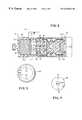
- FIG. 2is a cross-sectional view similar to FIG. 1, but showing the position of the various components of the device after the device has been actuated to start the timing sequence.
- elastomeric member 20will begin to return to its starting configuration, and in so doing will act on the fluid “F” causing it to flow through porous frit 28 and toward chamber 22 a where it will be absorbed by cellular mass 24 . As mass 24 expands, it will act on housing 18 causing it to return toward its starting position.
- the time required for housing and contact 32 to return to their starting positionis, of course, a function of the time required for the fluid “F” to flow from chamber 16 a to chamber 22 a which, in turn, is a function of the impedance to fluid flow offered by porous frit 28 and the ability of elastomeric member 20 to return to its uncompressed state.
- Rotatably carried by housing 66is a control knob 94 which is interconnected with member 70 by means of splines 94 b formed on a collar-like portion 94 a of control knob 94 .
- Splines 94 bare receivable within mating grooves 70 c formed in the enlarged diameter portion of support member 70 so that rotation of knob 94 will cause member 70 to rotate and move along threaded shank 78 c either to the right or left from the position shown in FIG. 8 .
- rotation of knob 94will vary distance “D-1” either increasing or decreasing it depending upon the direction of rotation of the knob.
Landscapes
- Physics & Mathematics (AREA)
- General Physics & Mathematics (AREA)
- Infusion, Injection, And Reservoir Apparatuses (AREA)
Abstract
Description
Claims (16)
Priority Applications (1)
| Application Number | Priority Date | Filing Date | Title |
|---|---|---|---|
| US09/316,767US6236624B1 (en) | 1999-05-21 | 1999-05-21 | Timing device |
Applications Claiming Priority (1)
| Application Number | Priority Date | Filing Date | Title |
|---|---|---|---|
| US09/316,767US6236624B1 (en) | 1999-05-21 | 1999-05-21 | Timing device |
Publications (1)
| Publication Number | Publication Date |
|---|---|
| US6236624B1true US6236624B1 (en) | 2001-05-22 |
Family
ID=23230590
Family Applications (1)
| Application Number | Title | Priority Date | Filing Date |
|---|---|---|---|
| US09/316,767Expired - Fee RelatedUS6236624B1 (en) | 1999-05-21 | 1999-05-21 | Timing device |
Country Status (1)
| Country | Link |
|---|---|
| US (1) | US6236624B1 (en) |
Cited By (39)
| Publication number | Priority date | Publication date | Assignee | Title |
|---|---|---|---|---|
| US20030109836A1 (en)* | 2001-12-07 | 2003-06-12 | Medrip Ltd. | Fluid flow meter for gravity fed intravenous fluid delivery systems |
| US20050033233A1 (en)* | 2003-08-04 | 2005-02-10 | Kriesel Marshall S. | Infusion apparatus with constant force spring energy source |
| US20050033232A1 (en)* | 2003-08-05 | 2005-02-10 | Kriesel Marshall S. | Infusion apparatus with modulated flow control |
| US20050038387A1 (en)* | 2003-08-04 | 2005-02-17 | Kriesel Marshall S. | Multichannel fluid delivery device |
| US20050263615A1 (en)* | 2004-05-26 | 2005-12-01 | Kriesel Marshall S | Fluid delivery apparatus with adjustable flow rate control |
| US20050277884A1 (en)* | 2004-05-26 | 2005-12-15 | Kriesel Marshall S | Fluid delivery apparatus with bellows reservoir |
| US20050277883A1 (en)* | 2004-05-26 | 2005-12-15 | Kriesel Marshall S | Fluid delivery device |
| US20050277882A1 (en)* | 2004-05-26 | 2005-12-15 | Kriesel Marshall S | Infusion apparatus |
| US20060195057A1 (en)* | 2005-02-18 | 2006-08-31 | Kriesel Marshall S | Fluid delivery apparatus with vial fill |
| US20060196552A1 (en)* | 2005-02-17 | 2006-09-07 | Kriesel Marshall S | Distal rate control device |
| US20060206052A1 (en)* | 2005-02-15 | 2006-09-14 | Kriesel Marshall S | Fluid delivery and mixing apparatus with flow rate control |
| US20070156090A1 (en)* | 2004-05-26 | 2007-07-05 | Kriesel Marshall S | Fluid delivery apparatus |
| US20070219501A1 (en)* | 2006-03-15 | 2007-09-20 | Kriesel Marshall S | Fluid dispensing apparatus |
| US20080009835A1 (en)* | 2005-02-17 | 2008-01-10 | Kriesel Marshall S | Fluid dispensing apparatus with flow rate control |
| US20080027376A1 (en)* | 2006-07-31 | 2008-01-31 | Kriesel Marshall S | Fluid dispensing device with additive |
| US20080243077A1 (en)* | 2007-04-02 | 2008-10-02 | Bivin Donald B | Fluid dispenser with uniformly collapsible reservoir |
| US20080319385A1 (en)* | 2007-06-25 | 2008-12-25 | Kriesel Marshall S | Fluid dispenser with additive sub-system |
| US20090024083A1 (en)* | 2007-06-25 | 2009-01-22 | Kriesel Marshall S | Fluid dispenser with additive sub-system |
| US20090076458A1 (en)* | 2004-10-21 | 2009-03-19 | Novo Nordisk A/S | Injection Device with Means for Signalling the Time Since the Last Injection |
| US20090112163A1 (en)* | 2007-10-31 | 2009-04-30 | Bivin Donald B | Fluid delivery device with variable force spring |
| US20090112149A1 (en)* | 2007-10-31 | 2009-04-30 | Kriesel Marshall S | Variable rate fluid dispenser |
| US20090211642A1 (en)* | 2008-02-27 | 2009-08-27 | John Morris Lynn | Monitoring apparatus |
| US20100056995A1 (en)* | 2008-09-03 | 2010-03-04 | Kriesel Marshall S | Two part fluid dispenser |
| US20100056998A1 (en)* | 2008-09-03 | 2010-03-04 | Kriesel Marshall S | Two part fluid dispenser |
| US20100056996A1 (en)* | 2008-09-03 | 2010-03-04 | Kriesel Marshall S | Two part fluid dispenser |
| US20100056997A1 (en)* | 2008-09-03 | 2010-03-04 | Kriesel Marshall S | Two part fluid dispenser with twin reservoir |
| US20100094219A1 (en)* | 2008-10-15 | 2010-04-15 | Kriesel Marshall S | Special purpose fluid dispenser with pre-filled reservoir |
| US7828772B2 (en) | 2006-03-15 | 2010-11-09 | Bioquiddity, Inc. | Fluid dispensing device |
| US20100312187A1 (en)* | 2009-06-03 | 2010-12-09 | Kriesel Marshall S | Pain management dispenser |
| US20110082422A1 (en)* | 2009-10-06 | 2011-04-07 | Serena Joshi | Fluid dispenser with non-electric fluid heating component |
| US20110208125A1 (en)* | 2008-08-29 | 2011-08-25 | Novo Nordisk A/S | Medical injection device with time delay indicator |
| US8057435B2 (en) | 2006-07-31 | 2011-11-15 | Kriesel Joshua W | Fluid dispenser |
| US8226609B2 (en) | 2007-06-25 | 2012-07-24 | Bioquiddity, Inc. | Fluid dispenser with additive sub-system |
| US8262282B2 (en) | 2008-02-27 | 2012-09-11 | Flotime, LLC | Monitoring apparatus |
| US8821454B2 (en) | 2010-05-12 | 2014-09-02 | Bioquiddity, Inc. | Apparatus for dispensing medicinal fluids and method of making same |
| US9669163B2 (en) | 2014-08-09 | 2017-06-06 | Bioq Pharma Incorporated | Apparatus for dispensing medicinal fluids and method of making same |
| US9737659B2 (en) | 2010-05-12 | 2017-08-22 | Bioq Pharma Incorporated | Apparatus for dispensing medicinal fluids and method of making same |
| US20180095425A1 (en)* | 2016-10-05 | 2018-04-05 | The Swatch Group Research And Development Ltd | Watch comprising a transmission device between a control member and the movement |
| CN111636980A (en)* | 2020-05-15 | 2020-09-08 | 大连理工大学 | A liquid propellant bellows tank |
Citations (16)
| Publication number | Priority date | Publication date | Assignee | Title |
|---|---|---|---|---|
| US2770941A (en) | 1955-05-10 | 1956-11-20 | Vincent A Flagiello | Air operated clock |
| US3171245A (en) | 1963-02-25 | 1965-03-02 | Breed Corp | Dashpot timer |
| US3353412A (en) | 1965-10-19 | 1967-11-21 | Bayside Watch Tool Co Inc | Mechanical timer |
| US3550458A (en) | 1969-06-23 | 1970-12-29 | Minnesota Mining & Mfg | Mechanical timer |
| US3563023A (en) | 1968-12-09 | 1971-02-16 | David S Breed | Liquid annular orifice dashpot timer |
| US3563024A (en) | 1969-08-27 | 1971-02-16 | David S Breed | Sharp edge orifice dashpot timer |
| US3603072A (en) | 1970-01-08 | 1971-09-07 | David S Breed | Liquid annular orifice dashpot timer with modified liquid |
| US3731021A (en) | 1970-09-11 | 1973-05-01 | Smiths Industries Ltd | Time delay switch with improved dashpot means |
| US3844311A (en) | 1972-11-10 | 1974-10-29 | H Mcswain | Valve control apparatus |
| US3933337A (en) | 1974-06-07 | 1976-01-20 | Acorn Engineering Company | Time-delayed automatic shut-off means for valves |
| US4315327A (en) | 1980-07-29 | 1982-02-09 | Bremer Edgar W | Air operated clock |
| US4436434A (en) | 1981-07-28 | 1984-03-13 | Kurt Stoll | Pneumatic timer |
| US4447161A (en) | 1981-05-14 | 1984-05-08 | Kurt Stoll | Pneumatic timer |
| US4569369A (en) | 1983-11-25 | 1986-02-11 | Isaac Rinkewich | Timer-controlled valve particularly for irrigation |
| US5343444A (en)* | 1992-03-25 | 1994-08-30 | Agut, S.A. | Pneumatic timer |
| US5445182A (en) | 1994-08-11 | 1995-08-29 | Sturman; Oded E. | Toggle fluid control valve |
- 1999
- 1999-05-21USUS09/316,767patent/US6236624B1/ennot_activeExpired - Fee Related
Patent Citations (16)
| Publication number | Priority date | Publication date | Assignee | Title |
|---|---|---|---|---|
| US2770941A (en) | 1955-05-10 | 1956-11-20 | Vincent A Flagiello | Air operated clock |
| US3171245A (en) | 1963-02-25 | 1965-03-02 | Breed Corp | Dashpot timer |
| US3353412A (en) | 1965-10-19 | 1967-11-21 | Bayside Watch Tool Co Inc | Mechanical timer |
| US3563023A (en) | 1968-12-09 | 1971-02-16 | David S Breed | Liquid annular orifice dashpot timer |
| US3550458A (en) | 1969-06-23 | 1970-12-29 | Minnesota Mining & Mfg | Mechanical timer |
| US3563024A (en) | 1969-08-27 | 1971-02-16 | David S Breed | Sharp edge orifice dashpot timer |
| US3603072A (en) | 1970-01-08 | 1971-09-07 | David S Breed | Liquid annular orifice dashpot timer with modified liquid |
| US3731021A (en) | 1970-09-11 | 1973-05-01 | Smiths Industries Ltd | Time delay switch with improved dashpot means |
| US3844311A (en) | 1972-11-10 | 1974-10-29 | H Mcswain | Valve control apparatus |
| US3933337A (en) | 1974-06-07 | 1976-01-20 | Acorn Engineering Company | Time-delayed automatic shut-off means for valves |
| US4315327A (en) | 1980-07-29 | 1982-02-09 | Bremer Edgar W | Air operated clock |
| US4447161A (en) | 1981-05-14 | 1984-05-08 | Kurt Stoll | Pneumatic timer |
| US4436434A (en) | 1981-07-28 | 1984-03-13 | Kurt Stoll | Pneumatic timer |
| US4569369A (en) | 1983-11-25 | 1986-02-11 | Isaac Rinkewich | Timer-controlled valve particularly for irrigation |
| US5343444A (en)* | 1992-03-25 | 1994-08-30 | Agut, S.A. | Pneumatic timer |
| US5445182A (en) | 1994-08-11 | 1995-08-29 | Sturman; Oded E. | Toggle fluid control valve |
Cited By (71)
| Publication number | Priority date | Publication date | Assignee | Title |
|---|---|---|---|---|
| WO2003048690A3 (en)* | 2001-12-07 | 2003-12-11 | Medrip Ltd | Fluid flow meter for gravity fed intravenous fluid delivery systems |
| US6679865B2 (en)* | 2001-12-07 | 2004-01-20 | Nedrip Ltd. | Fluid flow meter for gravity fed intravenous fluid delivery systems |
| US20030109836A1 (en)* | 2001-12-07 | 2003-06-12 | Medrip Ltd. | Fluid flow meter for gravity fed intravenous fluid delivery systems |
| US7169128B2 (en) | 2003-08-04 | 2007-01-30 | Bioquiddity, Inc. | Multichannel fluid delivery device |
| US20050033233A1 (en)* | 2003-08-04 | 2005-02-10 | Kriesel Marshall S. | Infusion apparatus with constant force spring energy source |
| US20050038387A1 (en)* | 2003-08-04 | 2005-02-17 | Kriesel Marshall S. | Multichannel fluid delivery device |
| CN100586503C (en)* | 2003-08-04 | 2010-02-03 | M.S.克里塞尔 | Infusion device with constant force spring energy source |
| US7789853B2 (en) | 2003-08-04 | 2010-09-07 | Bioquiddity, Inc. | Infusion apparatus with constant force spring energy source |
| US20080051701A1 (en)* | 2003-08-04 | 2008-02-28 | Kriesel Marshall S | Infusion apparatus with constant force spring energy source |
| WO2005016405A3 (en)* | 2003-08-04 | 2006-01-19 | Marshall S Kriesel | Infusion apparatus with constant force spring energy source |
| US7220244B2 (en) | 2003-08-04 | 2007-05-22 | Bioquiddity, Inc. | Infusion apparatus with constant force spring energy source |
| US20050033232A1 (en)* | 2003-08-05 | 2005-02-10 | Kriesel Marshall S. | Infusion apparatus with modulated flow control |
| US7220245B2 (en) | 2004-05-26 | 2007-05-22 | Kriesel Marshall S | Infusion apparatus |
| US20050263615A1 (en)* | 2004-05-26 | 2005-12-01 | Kriesel Marshall S | Fluid delivery apparatus with adjustable flow rate control |
| US7470253B2 (en) | 2004-05-26 | 2008-12-30 | Bioquiddity, Inc. | Fluid delivery apparatus with adjustable flow rate control |
| US20050277884A1 (en)* | 2004-05-26 | 2005-12-15 | Kriesel Marshall S | Fluid delivery apparatus with bellows reservoir |
| US20050277882A1 (en)* | 2004-05-26 | 2005-12-15 | Kriesel Marshall S | Infusion apparatus |
| US20070156090A1 (en)* | 2004-05-26 | 2007-07-05 | Kriesel Marshall S | Fluid delivery apparatus |
| US20050277883A1 (en)* | 2004-05-26 | 2005-12-15 | Kriesel Marshall S | Fluid delivery device |
| US9314573B2 (en) | 2004-10-21 | 2016-04-19 | Novo Nordisk A/S | Injection device with means for signalling the time since the last injection |
| US20090076458A1 (en)* | 2004-10-21 | 2009-03-19 | Novo Nordisk A/S | Injection Device with Means for Signalling the Time Since the Last Injection |
| US20060206052A1 (en)* | 2005-02-15 | 2006-09-14 | Kriesel Marshall S | Fluid delivery and mixing apparatus with flow rate control |
| US20080009835A1 (en)* | 2005-02-17 | 2008-01-10 | Kriesel Marshall S | Fluid dispensing apparatus with flow rate control |
| US7694938B2 (en) | 2005-02-17 | 2010-04-13 | Bioquiddity, Inc. | Distal rate control device |
| US20060196552A1 (en)* | 2005-02-17 | 2006-09-07 | Kriesel Marshall S | Distal rate control device |
| US20060195057A1 (en)* | 2005-02-18 | 2006-08-31 | Kriesel Marshall S | Fluid delivery apparatus with vial fill |
| US7837653B2 (en) | 2005-02-18 | 2010-11-23 | Bioquiddity, Inc. | Fluid delivery apparatus with vial fill |
| US20070219501A1 (en)* | 2006-03-15 | 2007-09-20 | Kriesel Marshall S | Fluid dispensing apparatus |
| US7828772B2 (en) | 2006-03-15 | 2010-11-09 | Bioquiddity, Inc. | Fluid dispensing device |
| US20110092904A1 (en)* | 2006-03-15 | 2011-04-21 | Kriesel Marshall S | Fluid dispensing device |
| US7993304B2 (en) | 2006-03-15 | 2011-08-09 | Bioquiddity, Inc. | Fluid dispensing apparatus |
| US20110282284A1 (en)* | 2006-03-15 | 2011-11-17 | Kriesel Marshall S | Fluid dispensing apparatus |
| US8672885B2 (en)* | 2006-03-15 | 2014-03-18 | Marshall S. Kriesel | Fluid dispensing device |
| US8292848B2 (en) | 2006-07-31 | 2012-10-23 | Bio Quiddity, Inc. | Fluid dispensing device with additive |
| US20080027376A1 (en)* | 2006-07-31 | 2008-01-31 | Kriesel Marshall S | Fluid dispensing device with additive |
| US8057435B2 (en) | 2006-07-31 | 2011-11-15 | Kriesel Joshua W | Fluid dispenser |
| US20080243077A1 (en)* | 2007-04-02 | 2008-10-02 | Bivin Donald B | Fluid dispenser with uniformly collapsible reservoir |
| US20090024083A1 (en)* | 2007-06-25 | 2009-01-22 | Kriesel Marshall S | Fluid dispenser with additive sub-system |
| US8211059B2 (en) | 2007-06-25 | 2012-07-03 | Kriesel Marshall S | Fluid dispenser with additive sub-system |
| US20080319385A1 (en)* | 2007-06-25 | 2008-12-25 | Kriesel Marshall S | Fluid dispenser with additive sub-system |
| US8226609B2 (en) | 2007-06-25 | 2012-07-24 | Bioquiddity, Inc. | Fluid dispenser with additive sub-system |
| US20090112149A1 (en)* | 2007-10-31 | 2009-04-30 | Kriesel Marshall S | Variable rate fluid dispenser |
| US7828770B2 (en)* | 2007-10-31 | 2010-11-09 | Bioquiddity, Inc. | Fluid delivery device with variable force spring |
| US20090112163A1 (en)* | 2007-10-31 | 2009-04-30 | Bivin Donald B | Fluid delivery device with variable force spring |
| US20100222741A1 (en)* | 2007-10-31 | 2010-09-02 | Bivin Donald B | Fluid delivery device with variable force spring |
| US8123723B2 (en)* | 2007-10-31 | 2012-02-28 | Bivin Donald B | Fluid delivery device with variable force spring |
| US8262282B2 (en) | 2008-02-27 | 2012-09-11 | Flotime, LLC | Monitoring apparatus |
| US7963692B2 (en) | 2008-02-27 | 2011-06-21 | Flotime, LLC | Monitoring apparatus |
| US20090211642A1 (en)* | 2008-02-27 | 2009-08-27 | John Morris Lynn | Monitoring apparatus |
| US8894611B2 (en) | 2008-08-29 | 2014-11-25 | Novo Nordisk A/S | Medical injection device with time delay indicator |
| US20110208125A1 (en)* | 2008-08-29 | 2011-08-25 | Novo Nordisk A/S | Medical injection device with time delay indicator |
| US20100056996A1 (en)* | 2008-09-03 | 2010-03-04 | Kriesel Marshall S | Two part fluid dispenser |
| US20100056998A1 (en)* | 2008-09-03 | 2010-03-04 | Kriesel Marshall S | Two part fluid dispenser |
| US20100056995A1 (en)* | 2008-09-03 | 2010-03-04 | Kriesel Marshall S | Two part fluid dispenser |
| US8083717B2 (en) | 2008-09-03 | 2011-12-27 | Bioquiddity, Inc. | Two part fluid dispenser with twin reservoir |
| US20100056997A1 (en)* | 2008-09-03 | 2010-03-04 | Kriesel Marshall S | Two part fluid dispenser with twin reservoir |
| US8622965B2 (en) | 2008-09-03 | 2014-01-07 | Bioquiddity, Inc. | Two part fluid dispenser |
| US8480656B2 (en) | 2008-09-03 | 2013-07-09 | Bioquiddity, Inc. | Two part fluid dispenser |
| US20100094219A1 (en)* | 2008-10-15 | 2010-04-15 | Kriesel Marshall S | Special purpose fluid dispenser with pre-filled reservoir |
| US8100890B2 (en) | 2008-10-15 | 2012-01-24 | Bioquiddity, Inc. | Special purpose fluid dispenser with pre-filled reservoir |
| US8287521B2 (en) | 2008-10-15 | 2012-10-16 | Bio Quiddity, Inc. | Special purpose fluid dispenser with pre-filled reservoir |
| US20100312187A1 (en)* | 2009-06-03 | 2010-12-09 | Kriesel Marshall S | Pain management dispenser |
| US8197445B2 (en) | 2009-06-03 | 2012-06-12 | Bioquiddity, Inc. | Pain management dispenser |
| US20110082422A1 (en)* | 2009-10-06 | 2011-04-07 | Serena Joshi | Fluid dispenser with non-electric fluid heating component |
| US8388571B2 (en) | 2009-10-06 | 2013-03-05 | Bioquiddity, Inc. | Fluid dispenser with non-electric fluid heating component |
| US8821454B2 (en) | 2010-05-12 | 2014-09-02 | Bioquiddity, Inc. | Apparatus for dispensing medicinal fluids and method of making same |
| US9737659B2 (en) | 2010-05-12 | 2017-08-22 | Bioq Pharma Incorporated | Apparatus for dispensing medicinal fluids and method of making same |
| US9669163B2 (en) | 2014-08-09 | 2017-06-06 | Bioq Pharma Incorporated | Apparatus for dispensing medicinal fluids and method of making same |
| US20180095425A1 (en)* | 2016-10-05 | 2018-04-05 | The Swatch Group Research And Development Ltd | Watch comprising a transmission device between a control member and the movement |
| US10120340B2 (en)* | 2016-10-05 | 2018-11-06 | The Swatch Group Research And Development Ltd | Watch comprising a transmission device between a control member and the movement |
| CN111636980A (en)* | 2020-05-15 | 2020-09-08 | 大连理工大学 | A liquid propellant bellows tank |
Similar Documents
| Publication | Publication Date | Title |
|---|---|---|
| US6236624B1 (en) | Timing device | |
| EP1585568B1 (en) | Injection device | |
| US11667017B2 (en) | Drive-in tool with improved safety device | |
| US4164635A (en) | Wall switch timer | |
| EP3552767B1 (en) | Pneumatic fastener driver | |
| ITPD970096A1 (en) | SAFETY AND REGULATING VALVE UNIT FOR A GAS SYSTEM, PARTICULARLY A HEATING SYSTEM | |
| EP0805274B1 (en) | Device for protecting a pump against dry running | |
| US11590639B2 (en) | Fluid damper and driving tool | |
| WO2000020930A1 (en) | Timing device | |
| US6446943B1 (en) | Gas spring pressure release mechanism | |
| US2778450A (en) | Accumulator for mechanical energy | |
| US4390855A (en) | Resetting device for manually operable rotary switch | |
| US3153706A (en) | Pneumatically-timed contact-holder | |
| US3264948A (en) | Two-stage timer mechanism | |
| JPS6144052Y2 (en) | ||
| CN222085222U (en) | A water distributor | |
| AT147731B (en) | Switch with compressed air extinguishing. | |
| JPH08159303A (en) | Valve flow adjusting device | |
| US9381634B2 (en) | Fastener driving tool | |
| RU2042173C1 (en) | Gas pressure regulator | |
| KR200320229Y1 (en) | Air timer | |
| SU853216A1 (en) | Apparatus for controlling working fluid flowrate | |
| SU1145363A1 (en) | Pneumatic apparatus for control of switching device | |
| HK1173397B (en) | Injection device | |
| JPH0581151B2 (en) |
Legal Events
| Date | Code | Title | Description |
|---|---|---|---|
| AS | Assignment | Owner name:SCIENCE INCORPORATED, MINNESOTA Free format text:ASSIGNMENT OF ASSIGNORS INTEREST;ASSIGNORS:KRIESEL, MARSHALL S.;FENG, WILLIAM W.;KAZEMZADEH, FARHAD;REEL/FRAME:011534/0759 Effective date:19981103 | |
| AS | Assignment | Owner name:ARLEEN M. CARLSON 2000 BCG CLAT C/O MR. JOHN K. FL Free format text:SECURITY INTEREST;ASSIGNOR:SCIENCE INCORPORATED;REEL/FRAME:013258/0828 Effective date:20011120 Owner name:ARLEEN M. CARLSON 2000 MCN CLAT C/O MR. JOHN K. FL Free format text:SECURITY INTEREST;ASSIGNOR:SCIENCE INCORPORATED;REEL/FRAME:013258/0828 Effective date:20011120 Owner name:BRATTAIN, DONALD, MINNESOTA Free format text:SECURITY INTEREST;ASSIGNOR:SCIENCE INCORPORATED;REEL/FRAME:013258/0828 Effective date:20011120 Owner name:EVERS, MICHAEL J., MINNESOTA Free format text:SECURITY INTEREST;ASSIGNOR:SCIENCE INCORPORATED;REEL/FRAME:013258/0828 Effective date:20011120 Owner name:FARLEY, WILLIAM F., D/B/A LIVINGSTON CAPITAL, MINN Free format text:SECURITY INTEREST;ASSIGNOR:SCIENCE INCORPORATED;REEL/FRAME:013258/0828 Effective date:20011120 Owner name:GROSSMAN INVESTMENTS, ATTN: LARRY WALLER, MINNESOT Free format text:SECURITY INTEREST;ASSIGNOR:SCIENCE INCORPORATED;REEL/FRAME:013258/0828 Effective date:20011120 Owner name:HODDER, WILLIAM A., MINNESOTA Free format text:SECURITY INTEREST;ASSIGNOR:SCIENCE INCORPORATED;REEL/FRAME:013258/0828 Effective date:20011120 Owner name:LUECK, BRUCE C., MINNESOTA Free format text:SECURITY INTEREST;ASSIGNOR:SCIENCE INCORPORATED;REEL/FRAME:013258/0828 Effective date:20011120 Owner name:MCGLYNN, BURTON J., FLORIDA Free format text:SECURITY INTEREST;ASSIGNOR:SCIENCE INCORPORATED;REEL/FRAME:013258/0828 Effective date:20011120 Owner name:OKABENA PARTNERSHIP V-8, BRUCE C. LUECK, PRESIDENT Free format text:SECURITY INTEREST;ASSIGNOR:SCIENCE INCORPORATED;REEL/FRAME:013258/0828 Effective date:20011120 Owner name:POCKET, A NOMINE PARTNERSHIP C/O MR. RANDALL J. SU Free format text:SECURITY INTEREST;ASSIGNOR:SCIENCE INCORPORATED;REEL/FRAME:013258/0828 Effective date:20011120 Owner name:REVOCABLE TRUST OF BARBARA C. GAGE, C/O MR. JOHN K Free format text:SECURITY INTEREST;ASSIGNOR:SCIENCE INCORPORATED;REEL/FRAME:013258/0828 Effective date:20011120 Owner name:REVOCABLE TRUST OF EDWIN C. GAGE C/O MR. JOHN K. F Free format text:SECURITY INTEREST;ASSIGNOR:SCIENCE INCORPORATED;REEL/FRAME:013258/0828 Effective date:20011120 Owner name:SIT INVESTMENT ASSOCIATES, INC., EUGENE C. SIT, MI Free format text:SECURITY INTEREST;ASSIGNOR:SCIENCE INCORPORATED;REEL/FRAME:013258/0828 Effective date:20011120 Owner name:TORGERSON, PAUL M., MINNESOTA Free format text:SECURITY INTEREST;ASSIGNOR:SCIENCE INCORPORATED;REEL/FRAME:013258/0828 Effective date:20011120 Owner name:WALLIN FAMILY FOUNDATION, WINSTON R. WALLIN, MINNE Free format text:SECURITY INTEREST;ASSIGNOR:SCIENCE INCORPORATED;REEL/FRAME:013258/0828 Effective date:20011120 | |
| FPAY | Fee payment | Year of fee payment:4 | |
| SULP | Surcharge for late payment | ||
| REMI | Maintenance fee reminder mailed | ||
| AS | Assignment | Owner name:SCIENCE INCORPORATED, MINNESOTA Free format text:RELEASE OF SECURITY AGREEMENT;ASSIGNORS:OKABENA PARTNERSIP V-8 BY OKABENA INVESTMENT SERVICES, INC. MANAGER;WINSTON R. WALLIN/WALLIN FAMILY FOUNDATION;WILLIAM F. FARLEY D/B/A LIVINGSTON CAPITAL;AND OTHERS;REEL/FRAME:019704/0733 Effective date:20070628 Owner name:PESCADERO BEACH HOLDINGS CORPORATION, CALIFORNIA Free format text:ASSIGNMENT OF ASSIGNORS INTEREST;ASSIGNOR:SCIENCO INCORPORATED;REEL/FRAME:019733/0235 Effective date:20070710 | |
| AS | Assignment | Owner name:PESCADERO BEACH HOLDINGS CORPORATION, CALIFORNIA Free format text:ASSIGNMENT OF ASSIGNORS INTEREST;ASSIGNOR:SCIENCE INCORPORATED;REEL/FRAME:019733/0298 Effective date:20070710 | |
| REMI | Maintenance fee reminder mailed | ||
| LAPS | Lapse for failure to pay maintenance fees | ||
| LAPS | Lapse for failure to pay maintenance fees | Free format text:PATENT EXPIRED FOR FAILURE TO PAY MAINTENANCE FEES (ORIGINAL EVENT CODE: EXP.); ENTITY STATUS OF PATENT OWNER: SMALL ENTITY | |
| STCH | Information on status: patent discontinuation | Free format text:PATENT EXPIRED DUE TO NONPAYMENT OF MAINTENANCE FEES UNDER 37 CFR 1.362 | |
| FP | Lapsed due to failure to pay maintenance fee | Effective date:20090522 |