US6236551B1 - Surge suppressor device - Google Patents
Surge suppressor deviceDownload PDFInfo
- Publication number
- US6236551B1 US6236551B1US09/591,800US59180000AUS6236551B1US 6236551 B1US6236551 B1US 6236551B1US 59180000 AUS59180000 AUS 59180000AUS 6236551 B1US6236551 B1US 6236551B1
- Authority
- US
- United States
- Prior art keywords
- surge
- surge suppressor
- inductor
- housing
- suppressor
- Prior art date
- Legal status (The legal status is an assumption and is not a legal conclusion. Google has not performed a legal analysis and makes no representation as to the accuracy of the status listed.)
- Expired - Lifetime
Links
- 230000000903blocking effectEffects0.000claimsabstractdescription40
- 239000004020conductorSubstances0.000claimsabstractdescription39
- 239000003989dielectric materialSubstances0.000claimsdescription7
- 230000008878couplingEffects0.000claimsdescription3
- 238000010168coupling processMethods0.000claimsdescription3
- 238000005859coupling reactionMethods0.000claimsdescription3
- 239000003990capacitorSubstances0.000claims9
- 230000001902propagating effectEffects0.000claims4
- 238000007599dischargingMethods0.000abstractdescription3
- 238000000034methodMethods0.000abstract1
- 238000003780insertionMethods0.000description13
- 230000037431insertionEffects0.000description13
- 230000005540biological transmissionEffects0.000description7
- 239000000463materialSubstances0.000description7
- 238000005259measurementMethods0.000description7
- 238000012804iterative processMethods0.000description5
- 230000007704transitionEffects0.000description5
- 238000010586diagramMethods0.000description4
- 230000007613environmental effectEffects0.000description4
- 238000012360testing methodMethods0.000description4
- 239000004606Fillers/ExtendersSubstances0.000description3
- 238000013461designMethods0.000description3
- 238000012797qualificationMethods0.000description3
- 239000004809TeflonSubstances0.000description2
- 229920006362Teflon®Polymers0.000description2
- 238000004891communicationMethods0.000description2
- 238000012938design processMethods0.000description2
- 238000004519manufacturing processMethods0.000description2
- 230000004048modificationEffects0.000description2
- 238000012986modificationMethods0.000description2
- 230000004044responseEffects0.000description2
- 2299100008537075 T6 aluminium alloyInorganic materials0.000description1
- 229910001369BrassInorganic materials0.000description1
- BQCADISMDOOEFD-UHFFFAOYSA-NSilverChemical compound[Ag]BQCADISMDOOEFD-UHFFFAOYSA-N0.000description1
- DMFGNRRURHSENX-UHFFFAOYSA-Nberyllium copperChemical compound[Be].[Cu]DMFGNRRURHSENX-UHFFFAOYSA-N0.000description1
- 230000002457bidirectional effectEffects0.000description1
- 239000010951brassSubstances0.000description1
- 230000015556catabolic processEffects0.000description1
- 230000008859changeEffects0.000description1
- 238000006731degradation reactionMethods0.000description1
- 230000001066destructive effectEffects0.000description1
- 230000000694effectsEffects0.000description1
- 230000006353environmental stressEffects0.000description1
- 230000003071parasitic effectEffects0.000description1
- 230000000704physical effectEffects0.000description1
- 230000008439repair processEffects0.000description1
- 238000000926separation methodMethods0.000description1
- 229910052709silverInorganic materials0.000description1
- 239000004332silverSubstances0.000description1
- 238000004088simulationMethods0.000description1
- 238000004513sizingMethods0.000description1
- 230000001629suppressionEffects0.000description1
- XLYOFNOQVPJJNP-UHFFFAOYSA-NwaterSubstancesOXLYOFNOQVPJJNP-UHFFFAOYSA-N0.000description1
Images


Classifications
- H—ELECTRICITY
- H01—ELECTRIC ELEMENTS
- H01Q—ANTENNAS, i.e. RADIO AERIALS
- H01Q1/00—Details of, or arrangements associated with, antennas
- H01Q1/12—Supports; Mounting means
- H01Q1/1271—Supports; Mounting means for mounting on windscreens
- H01Q1/1285—Supports; Mounting means for mounting on windscreens with capacitive feeding through the windscreen
- H—ELECTRICITY
- H01—ELECTRIC ELEMENTS
- H01Q—ANTENNAS, i.e. RADIO AERIALS
- H01Q1/00—Details of, or arrangements associated with, antennas
- H01Q1/50—Structural association of antennas with earthing switches, lead-in devices or lightning protectors
- H—ELECTRICITY
- H02—GENERATION; CONVERSION OR DISTRIBUTION OF ELECTRIC POWER
- H02H—EMERGENCY PROTECTIVE CIRCUIT ARRANGEMENTS
- H02H9/00—Emergency protective circuit arrangements for limiting excess current or voltage without disconnection
- H02H9/04—Emergency protective circuit arrangements for limiting excess current or voltage without disconnection responsive to excess voltage
- H02H9/044—Physical layout, materials not provided for elsewhere
Definitions
- the present inventiongenerally relates to a surge suppressor and more particularly to a surge suppressor having a spiral inductor and a surge blocking device.
- Communications equipment, computers, home stereo amplifiers, televisions, and other electronic devicesare increasingly manufactured using small electronic components which are very vulnerable to damage from electrical energy surges. Surge variations in power and transmission line voltages, as well as noise, can change the operating range of the equipment and can severely damage and/or destroy electronic devices. Moreover, these electronic devices can be very expensive to repair and replace. Therefore, a cost effective way to protect these components from power surges is needed.
- RF interferenceradio frequency
- the power and transmission linesact as large antennas that may extend over several miles, thereby collecting a significant amount of RF noise power from such sources as radio broadcast antennas.
- Another source of the harmful RF energyis from the equipment to be protected itself, such as computers. Older computers may emit significant amounts of RF interference.
- Another harmful sourceis conductive noise, which is generated by equipment connected to the power and transmission lines and which is conducted along the power lines to the equipment to be protected.
- Lightningis a complex electromagnetic energy source having potentials estimated at from 5 million to 20 million volts and currents reaching thousands of amperes.
- a surge suppression devicehaving a compact size, a low insertion loss, and a low voltage standing wave ratio (VSWR) that can protect hardware equipment from harmful electrical energy emitted from the above described sources.
- VSWRvoltage standing wave ratio
- the present inventionrelates to a surge suppressor for dissipating power surges.
- the surge suppressorprotects hardware equipment from electrical energy surges such as lightning.
- the surge suppressorincludes an inner conductor and a spiral inductor.
- the inner conductorpropagates signals therethrough during normal operation and the spiral inductor dissipates electrical energy during a surge condition to a ground connection.
- the spiral inductoris coupled between the inner conductor and the ground connection.
- the spiral inductoroperates at a predefined RF impedance to ground to conduct the signals along the inner conductor during normal operation to allow the RF signal to pass through the surge suppressor with minimal or no RF signal loss.
- the predefined RF impedance of the inductoris at least 10 times the operating impedance, i.e., 500 ohms for a 50 ohms system.
- the surge suppressormay also include a surge blocking device.
- the surge blocking deviceis inserted in series with the protected hardware for blocking the flow of electrical energy therethrough.
- the surge blocking devicewill be transparent to the transmitted RF signal, but will be effective in blocking the electrical energy surge from traveling through the inner conductor to the protected hardware.
- the spiral inductoris coupled to the surge blocking device and is shunted to ground for discharging the electrical energy created by the surge.
- the electrical energyis shunted to ground via the spiral inductor while the surge blocking device blocks the destructive lightning and EMP frequencies and the energy from passing through to the protected hardware.
- Advantages of the inventioninclude providing a surge suppressor that is matched to the system impedance to ensure low voltage standing wave ratio (VSWR) which is below 1.1:1 and a low insertion loss which is below 0.1 dB. Furthermore, the surge suppressor provides a large frequency band of operation, a low manufacturing cost, a stacked mechanical assembly for compact size, and low energy and voltage throughput.
- VSWRvoltage standing wave ratio
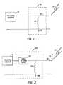
- FIG. 1illustrates a circuit diagram of one embodiment of the surge suppressor in accordance with the present invention
- FIG. 2illustrates a schematic circuit diagram of another embodiment of the surge suppressor in accordance with the present invention
- FIG. 3illustrates a perspective view of the surge suppressor shown in FIG. 2;
- FIG. 4illustrates a side view of the spiral inductor in accordance with the present invention
- FIG. 5illustrates a front view of the surge blocking device in accordance with the present invention.
- FIG. 6illustrates an iterative process to determine the inductance of the spiral inductor and the capacitance of the surge blocking device.
- FIG. 1illustrates a circuit diagram of one embodiment of the surge suppressor in accordance with the present invention.
- the surge suppressor 100protects hardware and equipment 110 from an electrical surge that can damage or destroy the hardware and equipment.
- a surge conditioncan arise in many different situations, however, typically arises when a lightning bolt 120 strikes a component or transmission line 105 which is coupled to the protected hardware 110 .
- Lightning surgesconsist of D.C. electrical energy and AC electrical energy up to approximately 1 MHz in frequency.
- the surge suppressor 100includes a spiral inductor 130 having a small foot print design, as shown in FIG. 4 .
- the diameter, surface area, thickness, and shape of the spiral inductor 130vary depending on the operating frequency and current handling capabilities desired. In the preferred embodiment, an iterative process (described below) is used to determine the diameter, surface area, thickness, and shape of the spiral inductor to meet the user's particular application.
- the diameter of the spiral inductor 130 of this package size and frequency rangeis typically 0.865 inches.
- the thickness of the spiral inductor 130 of this package size and frequency rangeis typically 0.062 inches.
- the spiral inductor 130spirals in an outward direction.
- the material composition of the spiral inductor 130is an important factor in determines the amount of charge that can be safely dissipated across the spiral inductor 130 .
- a high tensile strength materialallows the spiral inductor 130 to discharge a greater amount of current.
- the spiral inductor 130is made of a 7075-T6 Aluminum material. Alternatively, any material having a good tensile strength and conductivity can be used to manufacture the spiral inductor 130 .
- the protected hardware 110can be any communications equipment, PC computers, network connectors, or any other type of surge sensitive electronic equipment.
- the protected hardware 110may also contain a surge blocking device, as shown in FIG. 2, which shields the protected hardware 110 from an electrical surge.
- FIG. 2illustrates a schematic circuit diagram of another embodiment of the surge suppressor in accordance with the present invention.
- the surge suppressor 100is connected to an antenna 170 for receiving a surge.
- Antenna 170 or any other conducting surfacecan receive the lightning strike.
- the surge suppressor 100is positioned nearest to the protected hardware 110 to provide maximum protection.
- the preferred embodimentincludes a spiral inductor 130 for discharging an electrical surge to ground and a surge blocking device 150 for blocking A.C. and D.C. electrical energy.
- the spiral inductor 130 of the preferred embodimenthas been described above.
- the surge blocking device 150is a capacitive device realized in either lumped or distributed form.
- the surge blocking device 150can be parallel rods, coupling devices, conductive plates, or any other device or combination of elements which produce a capacitive effect.
- the capacitance of the surge blocking device 150can vary depending on the frequency of operation desired by the user. An iterative process (described below) is preferably utilized to determine the capacitance of the surge blocking device 150 .
- protected hardware 110receives and/or transmits RF signals through transmission line 105 .
- the surge suppressor 100operates in a bidirectional manner.
- the surge blocking device 150blocks the electrical energy created by the lightning strike and diverts the electrical energy through the spiral inductor 130 to ground 140 .
- the surge blocking device 150is designed to pass less than ⁇ 3 volts D.C., as per IEC 1000-4-5 8/20 usec 20 kA specification.
- Spiral inductor 130should be of sufficient conductivity and cross sectional area to dissipate electrical energy corresponding to the aforementioned signal specification.
- the minimum frequency range of operationis 1.7 GHz to 2.3 GHz; within which the insertion loss is specified less than 0.1 dB and the VSWR is specified less than 1.1:1.
- the values produced abovecan vary depending on the frequency range, degree of surge protection, and RF performance desired.
- FIG. 3illustrates a perspective view of the surge suppressor shown in FIG. 2 .
- the surge suppressor 100includes a surge blocking device 250 , a spiral inductor 230 , an inner conductor 215 , and a housing 220 having a cavity 222 , a surge port 255 , and a protected port 260 .
- the inner conductor 215is positioned concentric with and located in the cavity 222 of housing 220 .
- the surge port 255is coupled to transmission line 105 or antenna 170 and the protected port 260 is coupled to the protected hardware 110 , as shown in FIGS. 2 and 3.
- the surgepropagates into the surge port 255 via the inner conductor 215 . Thereafter, the surge is dissipated to a ground connection via the spiral inductor 230 . Hence, the surge is prohibited from reaching the protected port 260 and the protected hardware 110 .
- the inner conductor 215transmits and receives RF signals.
- the inner conductor 215can be made of any conductive material.
- the inner conductor 215is a coaxial cable and is made of a beryllium copper material.
- insulating membersDisposed at various locations throughout the housing 220 are insulating members. Preferably, there is a first and a second 226 , 228 insulating member.
- the insulating members 226 , 228electrically isolates the inner conductor 215 from the housing 220 .
- the insulating members 226 , 228may be made of a dielectric material such Teflon which has a dielectric constant of approximately 2.3.
- the insulating members 226 , 228are typically cylindrically shaped with a center hole.
- the surge suppressor 100has various segments each of which are structured to form a desired impedance, i.e., 50 ohms. Each adjacent segment is coupled to one another. The various segments will be described starting at surge port 255 and ending at protected port 260 . Each segment will be labeled A through H.
- the inner conductor 215is located at segments A, B, C, G, and H and has an outer radius of approximately 60 mils.
- Segments 215 A and 215 Binclude an inner conductor 215 surrounded by an air dielectric.
- the inner radius of the cavity 222 of segment 215 Bis approximately 137.8 mils.
- Segment 215 Cincludes an inner conductor 215 supported and surrounded by the first insulating member 226 .
- the first insulating member 226has an inner radius of approximately 57.5 mils, an outer radius of approximately 200 mils, and a length of approximately 325 mils.
- the inner radius of the cavity 222is approximately 200 mils.
- Segment 215 Dincludes an extender 240 that couples the inner conductor 215 to the spiral inductor 230 .
- Extender 240is disposed in the cavity 222 .
- the cavity 222forms a 45 degree angle. The 45 degree angle allows a low discontinuity match between the 50 ohm line and the spiral inductor 230 .
- the extender 240has an outer radius of approximately 140 mils and is made of a silver plated brass material.
- Segment 215 Eincludes a spiral inductor 230 disposed within the cavity 222 .
- the spiral inductor 230has an inner radius of approximately 62.5 mils and an outer radius of approximately 432.5 mils.
- the inner edge 231 of the spiral inductor 230is coupled to inner conductor 215 .
- the outer edge 232 of the spiral inductor 230is coupled to housing 220 .
- the spiral inductor 230may be of a particular known type such as the Archemedes, Logarithmic, or Hyperbolic spiral, or a combination of these spirals.
- the inner radius of the cavity 222is approximately 432.5 mils.
- the housing 220is coupled to a common ground connection to discharge the electrical energy.
- the electrical energyfirst reaches the inner edge 231 of the spiral inductor 230 .
- the electrical energyis then dissipated through the spirals of the spiral inductor 230 in an outward direction. Once the electrical energy reaches the outer edge 232 , the electrical energy is dissipated to ground through housing 220 .
- Segment 215 Fincludes a surge blocking device 250 disposed within the cavity 222 which has an inner radius of approximately 400 mils.
- the surge blocking device 250is typically a capacitive device realized in either lumped or distributed form.
- the capacitive deviceincludes two electrodes.
- the first electrodeincludes a first plate 251 A and a first transition 252 A.
- the second electrodeincludes a second plate 251 B and a second transition 252 B.
- the radius of each plate 251 A, 251 Bis approximately 243 mils and the thickness is approximately 50 mils.
- the radius of each transition 252 A, 252 Bis approximately 92.5 mils and the thickness is approximately 186 mils.
- Each plate 251 A, 251 Bis more capacitive than each transition 252 A, 252 B.
- the surge blocking device 250is designed such that the two plates 251 A, 251 B and two transitions 252 A, 252 B collectively form approximately a 50 ohm impedance path.
- a dielectric material 253such as Teflon is disposed between the two plates.
- the thickness of the dielectric material 253is approximately 20 mils.
- the distance between the platescan be varied as well as the dielectric material used.
- the dimensions, shape, size, and distance between the platesare chosen to achieve a desired impedance for the selected frequency range of operation.
- the surge blocking device 250may be located outside the housing 220 .
- Segment 215 Gincludes an inner conductor 215 supported and surrounded by the second insulating member 228 .
- the second insulating member 228has an inner radius of approximately 57.5 mils, an outer radius of approximately 200 mils, and a length of approximately 150 mils.
- the size and shape of the insulating members 226 , 228are designed such that they form a structure having a desired impedance, i.e., 50 ohms.
- the inner radius of cavity 222is approximately 200 mils.
- the housing 220can be made up of one or more structures for easy disassembly and part replacement. O-rings 245 are used to weather proof the surge suppressor 100 such that no moisture or water can enter the housing 220 . As shown in FIGS. 3 and 4, the spiral inductor 230 and the surge blocking device 250 are disposed inside the cavity 222 to achieve a compact size. In one embodiment, the spiral inductor 235 and the surge blocking device 230 are self-aligned within cavity 222 .
- the surge suppressor 100is preferably impedance matched to the system to ensure a low VSWR.
- the impedance of the surge suppressor 100is 50 ohms at both the surge port 255 and the protected port 260 .
- FIG. 4illustrates a side view of the spiral inductor as shown in accordance with the present invention.
- the inner edge 231forms a radius of approximately 62.5 mils.
- the outer edge 232forms a radius of approximately 432.5 mils.
- the spiral inductor 230spirals in an outward direction.
- the spiral inductor 230 of a preferred embodimenthas three spirals. The number of spirals and thickness of each spiral can be varied depending on the user's particular application.
- FIG. 5illustrates a front view of the surge blocking device 250 in accordance with the present invention.
- the surge blocking device 250is described throughout the specification, for example, as segment 215 F.
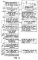
- FIG. 6illustrates an iterative process to determine the inductance of the spiral inductor.
- the iterative processcan also be used to calculate the capacitance of the surge blocking device for the user's particular application.
- a cutoff frequencyis determined by choosing a lower bandwidth limit and dividing by 8.
- a desired impedanceis chosen.
- the cut-off frequencydefines the lower end of user bandwidth.
- the desired impedanceis typically 50 ohms, but may be selected to be another value as needed.
- the inductorhas a value of 18.7 nH and the capacitive device has a value of 7.5 pF.
- the cavity dimensions of the surge suppressor and inductor constraintsare defined.
- the minimum dimensions of the surge suppressor's cavityare determined largely by the diameter of the connector used, i.e, N-type, BNC, etc.
- the inductor constraintswill include sizing constraints, such as the inner diameter of the cavity, and operating constraints such as the required conductivity, current handling, rigidity, type and thickness of the inductor material used.
- a spiral inductoris designed to meet all of these requirements, as shown in step 608 .
- the designed spiral inductorwill possess the calculated inductance to provide the necessary cut-off frequency, and the physical size and shape to fit into the required housing and conduct the necessary current during a surge without failing.
- the spiral inductormay be of a particular known type such as the Archemedes, Logarithmic or Hyperbolic spiral, or a combination of these spirals. Further, the spiral inductor may be of a shape resulting from two or more overlapped spirals.
- the spiral inductoris preferably designed using a RF modeling system, such as the HP 85123A, so that a more accurate simulation of the inductor can be performed.
- the spiralis fabricated, placed in a housing identical to its eventual operating environment, and tested to determine if the measured inductance is approximately equivalent to the desired inductance, as shown in step 610 .
- placing a circuit element within a grounded enclosureintroduces parasitic effects which must be accounted for if proper operation is to be achieved.
- the spiralis tested using conventionally-known RF test equipment such as a HP 8753 automatic network analyzer. If the test results indicate an unacceptable deviation between measured and desired inductance, the spiral inductor design process is repeated as shown in step 610 .
- a surge suppressor having a thru lineis measured, as shown in step 612 .
- the thru measurementis made to provide a baseline insertion loss measurement over the RF frequency of interest.
- the frequency range of interestis 1.7 GHz to 2.3 GHz.
- a surge suppressor having a thru line of the same dimensions measured in step 612 and the spiral inductor coupled from the thru line to ground (in shunt)is measured for insertion loss over the RF frequency range of interest. This measurement can then be compared to the previous thru measurement to indicate how much insertion loss degradation occurs with the addition of the shunt spiral inductor. If the insertion loss of the thru line plus shunt inductor is not within an acceptable range, steps 608 , 610 , and 612 are repeated. Other measurements, for instance, single port measurements may be used instead of, or in addition to the insertion loss measurement for qualifying the surge suppressor.
- a surge blocking series capacitive deviceis designed for inclusion within the surge suppressor, as shown in step 616 .
- the capacitive deviceis designed to possess the calculated capacitance, fit within the specified inner diameter of the cavity, and possess the physical properties to withstand a surge condition.
- the combination of the thru line, shunt spiral inductor, and series capacitive devicemay be simulated using a two or three dimensional CAD system. If used, modifications may be made to the design of the shunt spiral inductor, series surge blocking capacitive device and/or their separation to further optimize the surge suppressor's performance. In particular, it has been found that varying the shape and size of the capacitive device's electrodes results in changing the effective inductance of the shunt spiral inductor to further optimize circuit performance.
- a new surge suppressor incorporating the thru line, the shunt spiral inductor, and the series surge blocking capacitive deviceis fabricated and tested using the aforementioned or similar testing equipment. If the surge suppressor exhibits unacceptable insertion loss over the desired frequency range, the capacitive device design and/or its location along the thru line may be modified to tune the response to the desired level. Specifically, the capacitive device's gapping, diameter, and dielectric material may be altered to tune the insertion loss response within acceptable limits. If capacitive device modification is unsuccessful in tuning the desired parameter(s) to within acceptable limits, steps 608 , 610 , 612 , 614 , and 616 are repeated.
- the surge suppressorexhibits an acceptable insertion loss and/or other qualifying parameters, it is submitted for RF power handling and environmental testing, as shown in step 620 . Specifically, the surge suppressor is exposed to high levels of RF energy and environmental, temperature and vibrational conditions likely to be experienced during operation. If the surge suppressor fails to operate over a predetermined range, steps 608 , 610 , 612 , 614 , 616 , and 618 are repeated.
- surge qualificationmay entail exposing the surge suppressor to high current pulses under various environmental conditions to simulate a lightning strike.
- steps 606 , 608 , 612 , 614 , 620 and 622need be performed. Specifically, only the inductance value of the spiral shunt inductor need be determined and tested. Subsequently, the insertion loss and/or other parameter(s) of a thru line is used as the qualifying parameter to determine if the thru line plus the shunt spiral inductor operates within an acceptable window within the desired frequency range. Finally, RF power handling, environmental, and surge qualification occurs as described above.
Landscapes
- Emergency Protection Circuit Devices (AREA)
- Coils Or Transformers For Communication (AREA)
Abstract
Description
Claims (39)
Priority Applications (1)
| Application Number | Priority Date | Filing Date | Title |
|---|---|---|---|
| US09/591,800US6236551B1 (en) | 1997-10-14 | 2000-06-12 | Surge suppressor device |
Applications Claiming Priority (4)
| Application Number | Priority Date | Filing Date | Title |
|---|---|---|---|
| US6209797P | 1997-10-14 | 1997-10-14 | |
| US09/044,216US6061223A (en) | 1997-10-14 | 1998-03-18 | Surge suppressor device |
| US09/309,397US6115227A (en) | 1997-10-14 | 1999-05-07 | Surge suppressor device |
| US09/591,800US6236551B1 (en) | 1997-10-14 | 2000-06-12 | Surge suppressor device |
Related Parent Applications (1)
| Application Number | Title | Priority Date | Filing Date |
|---|---|---|---|
| US09/309,397ContinuationUS6115227A (en) | 1997-10-14 | 1999-05-07 | Surge suppressor device |
Publications (1)
| Publication Number | Publication Date |
|---|---|
| US6236551B1true US6236551B1 (en) | 2001-05-22 |
Family
ID=26721295
Family Applications (3)
| Application Number | Title | Priority Date | Filing Date |
|---|---|---|---|
| US09/044,216Expired - LifetimeUS6061223A (en) | 1997-10-14 | 1998-03-18 | Surge suppressor device |
| US09/309,397Expired - LifetimeUS6115227A (en) | 1997-10-14 | 1999-05-07 | Surge suppressor device |
| US09/591,800Expired - LifetimeUS6236551B1 (en) | 1997-10-14 | 2000-06-12 | Surge suppressor device |
Family Applications Before (2)
| Application Number | Title | Priority Date | Filing Date |
|---|---|---|---|
| US09/044,216Expired - LifetimeUS6061223A (en) | 1997-10-14 | 1998-03-18 | Surge suppressor device |
| US09/309,397Expired - LifetimeUS6115227A (en) | 1997-10-14 | 1999-05-07 | Surge suppressor device |
Country Status (9)
| Country | Link |
|---|---|
| US (3) | US6061223A (en) |
| EP (1) | EP1023754B1 (en) |
| KR (1) | KR20010015726A (en) |
| CN (1) | CN1275253A (en) |
| AU (1) | AU9115598A (en) |
| CA (1) | CA2305514C (en) |
| DE (1) | DE69820101T2 (en) |
| ES (1) | ES2206985T3 (en) |
| WO (1) | WO1999019957A1 (en) |
Cited By (56)
| Publication number | Priority date | Publication date | Assignee | Title |
|---|---|---|---|---|
| US20030072121A1 (en)* | 2001-10-12 | 2003-04-17 | Polyphaser Corporation | Rf surge protection device |
| US20030179533A1 (en)* | 2002-03-21 | 2003-09-25 | Polyphaser Corporation | Isolated shield coaxial surge suppressor |
| US20040042149A1 (en)* | 2002-04-15 | 2004-03-04 | Edward Devine | Surge lightning protection device |
| US20040130388A1 (en)* | 2001-01-18 | 2004-07-08 | Christian Block | Electric circuit module, circuit module arrangement and use of said circuit module and of said circuit module arrangement |
| US20040169986A1 (en)* | 2001-06-15 | 2004-09-02 | Kauffman George M. | Protective device |
| US20040264095A1 (en)* | 2001-09-28 | 2004-12-30 | Christian Block | Circuit arrangement, switching module comprising said circuit arrangement and use of said switching module |
| US20050059371A1 (en)* | 2001-09-28 | 2005-03-17 | Christian Block | Circuit arrangement, switching module comprising said circuit arrangement and use of switching module |
| US20060021784A1 (en)* | 2002-03-13 | 2006-02-02 | Garmong Victor H | Shielded cable entry ports and assemblies |
| US20060146458A1 (en)* | 2005-01-03 | 2006-07-06 | Huberag | Surge suppressor with increased surge current capability |
| US7094104B1 (en) | 2005-05-04 | 2006-08-22 | Andrew Corporation | In-line coaxial circuit assembly |
| US20070025043A1 (en)* | 2005-07-29 | 2007-02-01 | Tdk Corporation | Surge absorption element and surge absorption circuit |
| US20070053130A1 (en)* | 2005-09-01 | 2007-03-08 | Andrew Corporation | Offset Planar Coil Coaxial Surge Suppressor |
| US20070076343A1 (en)* | 2005-09-30 | 2007-04-05 | Tdk Corporation | Connector |
| US20070081287A1 (en)* | 2005-10-07 | 2007-04-12 | Andrew Corporation | Multiple Planar Inductor Coaxial Surge Suppressor |
| US20070097583A1 (en)* | 2005-10-31 | 2007-05-03 | Andrew Corporation | Tuned Coil Coaxial Surge Suppressor |
| US20070165352A1 (en)* | 2006-01-13 | 2007-07-19 | Andrew Corporation | Multiple Planar Inductive Loop Surge Suppressor |
| US20070268645A1 (en)* | 2006-05-22 | 2007-11-22 | Andrew Corporation | Tungsten Shorting Stub and Method of Manufacture |
| US20080170346A1 (en)* | 2007-01-17 | 2008-07-17 | Andrew Corporation | Folded Surface Capacitor In-line Assembly |
| US20080192401A1 (en)* | 2004-11-30 | 2008-08-14 | Tdk Corporation | Surge absorption circuit |
| US20090103226A1 (en)* | 2007-10-18 | 2009-04-23 | Polyphaser Corporation | Surge suppression device having one or more rings |
| US20090109584A1 (en)* | 2007-10-30 | 2009-04-30 | Polyphaser Corporation | Surge protection circuit for passing dc and rf signals |
| US20090284888A1 (en)* | 2008-05-19 | 2009-11-19 | Polyphaser Corporation | Dc and rf pass broadband surge suppressor |
| US20100265625A1 (en)* | 2009-04-17 | 2010-10-21 | John Mezzalingua Associates, Inc. | Coaxial broadband surge protector |
| US20110075312A1 (en)* | 2009-09-25 | 2011-03-31 | Erdogan Alkan | Surge protection device with improved response time |
| US20110075311A1 (en)* | 2009-09-25 | 2011-03-31 | Erdogan Alkan | Surge protection device for isolating premise devices |
| US20110077884A1 (en)* | 2008-11-17 | 2011-03-31 | Rochester Institute Of Technology | Internal coaxial cable connector integrated circuit and method of use thereof |
| US20110074388A1 (en)* | 2008-11-17 | 2011-03-31 | Rochester Institute Of Technology | Embedded coupler device and method of use thereoff |
| US20110080158A1 (en)* | 2007-09-24 | 2011-04-07 | John Mezzalingua Associates, Inc. | Coaxial cable connector with internal floating ground circuitry and method of use thereof |
| US20110080057A1 (en)* | 2008-11-17 | 2011-04-07 | Rochester Institute Of Technology | Power harvesting device and method of use thereof |
| US20110080683A1 (en)* | 2009-10-02 | 2011-04-07 | Jones Jonathan L | Rf coaxial surge protectors with non-linear protection devices |
| US20110130034A1 (en)* | 2008-11-17 | 2011-06-02 | John Mezzalingua Associates Inc. | Coaxial connector with integrated molded substrate and method of use thereof |
| US20110159727A1 (en)* | 2009-12-28 | 2011-06-30 | Matt Howard | Power distribution device |
| US20110161050A1 (en)* | 2009-12-03 | 2011-06-30 | John Mezzalingua Associates, Inc. | Coaxial cable connector parameter monitoring system |
| US20110235229A1 (en)* | 2010-03-26 | 2011-09-29 | Nguyen Eric H | Ethernet surge protector |
| US20110292557A1 (en)* | 2010-05-26 | 2011-12-01 | Chris Penwell | Dc block rf coaxial devices |
| US8116046B2 (en) | 2002-10-02 | 2012-02-14 | Epcos Ag | Circuit arrangement that includes a device to protect against electrostatic discharge |
| US8228656B2 (en) | 2007-09-12 | 2012-07-24 | Kauffman George M | Protective device for a radio frequency transmission line |
| US20130090010A1 (en)* | 2011-10-11 | 2013-04-11 | Commscope, Inc. Of North Carolina | Surge Protector Components Having a Plurality of Spark Gap Members Between a Central Conductor and an Outer Housing |
| US8432693B2 (en) | 2010-05-04 | 2013-04-30 | Transtector Systems, Inc. | High power band pass RF filter having a gas tube for surge suppression |
| US8441795B2 (en) | 2010-05-04 | 2013-05-14 | Transtector Systems, Inc. | High power band pass RF filter having a gas tube for surge suppression |
| US8456789B2 (en) | 2010-12-15 | 2013-06-04 | Andrew Llc | Tunable coaxial surge arrestor |
| US8604936B2 (en) | 2010-12-13 | 2013-12-10 | Ppc Broadband, Inc. | Coaxial cable connector, system and method of use thereof |
| US8611062B2 (en) | 2010-05-13 | 2013-12-17 | Transtector Systems, Inc. | Surge current sensor and surge protection system including the same |
| US8730637B2 (en) | 2010-12-17 | 2014-05-20 | Transtector Systems, Inc. | Surge protection devices that fail as an open circuit |
| US8730640B2 (en) | 2010-05-11 | 2014-05-20 | Transtector Systems, Inc. | DC pass RF protector having a surge suppression module |
| US8773255B2 (en) | 2007-09-24 | 2014-07-08 | Ppc Broadband, Inc. | Status sensing and reporting interface |
| US9048662B2 (en) | 2012-03-19 | 2015-06-02 | Transtector Systems, Inc. | DC power surge protector |
| US9054514B2 (en) | 2012-02-10 | 2015-06-09 | Transtector Systems, Inc. | Reduced let through voltage transient protection or suppression circuit |
| US9124093B2 (en) | 2012-09-21 | 2015-09-01 | Transtector Systems, Inc. | Rail surge voltage protector with fail disconnect |
| US9190837B2 (en) | 2012-05-03 | 2015-11-17 | Transtector Systems, Inc. | Rigid flex electromagnetic pulse protection device |
| US9924609B2 (en) | 2015-07-24 | 2018-03-20 | Transtector Systems, Inc. | Modular protection cabinet with flexible backplane |
| US9991697B1 (en) | 2016-12-06 | 2018-06-05 | Transtector Systems, Inc. | Fail open or fail short surge protector |
| US10129993B2 (en) | 2015-06-09 | 2018-11-13 | Transtector Systems, Inc. | Sealed enclosure for protecting electronics |
| US10193335B2 (en) | 2015-10-27 | 2019-01-29 | Transtector Systems, Inc. | Radio frequency surge protector with matched piston-cylinder cavity shape |
| US10356928B2 (en) | 2015-07-24 | 2019-07-16 | Transtector Systems, Inc. | Modular protection cabinet with flexible backplane |
| US10588236B2 (en) | 2015-07-24 | 2020-03-10 | Transtector Systems, Inc. | Modular protection cabinet with flexible backplane |
Families Citing this family (16)
| Publication number | Priority date | Publication date | Assignee | Title |
|---|---|---|---|---|
| US6061223A (en)* | 1997-10-14 | 2000-05-09 | Polyphaser Corporation | Surge suppressor device |
| PT1114418E (en)* | 1999-07-13 | 2009-03-24 | Koninkl Philips Electronics Nv | Device for scanning an information carrier, method of manufacturing, and information carrier |
| US6452773B1 (en) | 2000-03-21 | 2002-09-17 | Andrew Corporation | Broadband shorted stub surge protector |
| US6636407B1 (en) | 2000-09-13 | 2003-10-21 | Andrew Corporation | Broadband surge protector for RF/DC carrying conductor |
| DE10212365C1 (en)* | 2002-03-20 | 2003-08-21 | Rosenberger Hochfrequenztech | Electrical coaxial connector with overvoltage protection provided by capacitor with opposing capacitor plates coupled to inner conductor on input and output sides and axial coil coupled to outer conductor |
| KR100653440B1 (en)* | 2002-08-03 | 2006-12-01 | 주식회사 케이엠더블유 | Bias-tee device and its center conductor device |
| US7613172B2 (en)* | 2003-12-24 | 2009-11-03 | Watchguard Technologies, Inc. | Method and apparatus for controlling unsolicited messaging |
| DE102007030157A1 (en) | 2007-06-27 | 2009-01-08 | Phoenix Contact Gmbh & Co. Kg | Tunable λ / 4 filter assembly |
| US7623332B2 (en)* | 2008-01-31 | 2009-11-24 | Commscope, Inc. Of North Carolina | Low bypass fine arrestor |
| US8248740B2 (en)* | 2008-09-19 | 2012-08-21 | Advanced Fusion Systems, Llc | High speed current shunt |
| US8810989B2 (en)* | 2011-04-18 | 2014-08-19 | Alcatel Lucent | DC pass filter using flat inductor in cavity |
| US8858262B2 (en)* | 2012-12-04 | 2014-10-14 | Genesis Technology Usa, Inc. | F-connector with integrated surge protection |
| CN104953576B (en)* | 2015-05-15 | 2017-12-08 | 湖南中普技术股份有限公司 | A kind of integrated form radio frequency lightning protection device and integrated lightening arresting method |
| FR3061813B1 (en)* | 2017-01-06 | 2021-09-10 | Citel | INTEGRATED OVERVOLTAGE PROTECTION COMPONENT, ESPECIALLY FOR A COAXIAL CABLE SYSTEM |
| US20230163537A1 (en)* | 2021-11-22 | 2023-05-25 | Corning Optical Communications Rf Llc | Devices, assemblies, and methods for terminating coaxial radiofrequency ports |
| KR102715761B1 (en)* | 2023-04-10 | 2024-10-11 | 한국기술교육대학교 산학협력단 | Method for calculating proper capacity of surge protection device for energy storage system |
Citations (18)
| Publication number | Priority date | Publication date | Assignee | Title |
|---|---|---|---|---|
| US3845358A (en) | 1973-06-29 | 1974-10-29 | Gen Electric | Integrated polycrystalline varistor surge protective device for high frequency applications |
| US4047120A (en) | 1976-07-15 | 1977-09-06 | The United States Of America As Represented By The Secretary Of The Navy | Transient suppression circuit for push-pull switching amplifiers |
| US4262317A (en) | 1979-03-22 | 1981-04-14 | Reliable Electric Company | Line protector for a communications circuit |
| US4359764A (en) | 1980-04-08 | 1982-11-16 | Block Roger R | Connector for electromagnetic impulse suppression |
| US4384331A (en) | 1979-04-23 | 1983-05-17 | Nissan Motor Company, Limited | Noise suppressor for vehicle digital system |
| US4409637A (en) | 1980-04-08 | 1983-10-11 | Block Roger R | Connector for electromagnetic impulse suppression |
| US4554608A (en) | 1982-11-15 | 1985-11-19 | Block Roger R | Connector for electromagnetic impulse suppression |
| US4563720A (en) | 1984-04-17 | 1986-01-07 | General Semiconductor Industries, Inc. | Hybrid AC line transient suppressor |
| US4689713A (en) | 1985-06-12 | 1987-08-25 | Les Cables De Lyon | High voltage surge protection for electrical power line |
| US4727350A (en) | 1986-04-28 | 1988-02-23 | Hitoshi Ohkubo | Surge absorber |
| US4984146A (en) | 1990-03-27 | 1991-01-08 | International Business Machines Corporation | Suppression of radiated EMI for power supplies |
| US5053910A (en) | 1989-10-16 | 1991-10-01 | Perma Power Electronics, Inc. | Surge suppressor for coaxial transmission line |
| US5057964A (en) | 1986-12-17 | 1991-10-15 | Northern Telecom Limited | Surge protector for telecommunications terminals |
| US5122921A (en) | 1990-04-26 | 1992-06-16 | Industrial Communication Engineers, Ltd. | Device for electromagnetic static and voltage suppression |
| US5321573A (en) | 1992-07-16 | 1994-06-14 | Dale Electronics, Inc. | Monolythic surge suppressor |
| US5617284A (en) | 1994-08-05 | 1997-04-01 | Paradise; Rick | Power surge protection apparatus and method |
| US5667298A (en) | 1996-01-16 | 1997-09-16 | Cedarapids, Inc. | Portable concrete mixer with weigh/surge systems |
| US6115227A (en)* | 1997-10-14 | 2000-09-05 | Polyphaser Corporation | Surge suppressor device |
Family Cites Families (2)
| Publication number | Priority date | Publication date | Assignee | Title |
|---|---|---|---|---|
| US4985800A (en)* | 1989-10-30 | 1991-01-15 | Feldman Nathan W | Lighting protection apparatus for RF equipment and the like |
| ATE198390T1 (en)* | 1993-10-07 | 2001-01-15 | Andrew Corp | OVERVOLTAGE PROTECTION |
- 1998
- 1998-03-18USUS09/044,216patent/US6061223A/ennot_activeExpired - Lifetime
- 1998-08-20EPEP98943331Apatent/EP1023754B1/ennot_activeExpired - Lifetime
- 1998-08-20AUAU91155/98Apatent/AU9115598A/ennot_activeAbandoned
- 1998-08-20ESES98943331Tpatent/ES2206985T3/ennot_activeExpired - Lifetime
- 1998-08-20WOPCT/US1998/017461patent/WO1999019957A1/enactiveIP Right Grant
- 1998-08-20CACA002305514Apatent/CA2305514C/ennot_activeExpired - Lifetime
- 1998-08-20DEDE69820101Tpatent/DE69820101T2/ennot_activeExpired - Lifetime
- 1998-08-20KRKR1020007003854Apatent/KR20010015726A/ennot_activeWithdrawn
- 1998-08-20CNCN98810091.6Apatent/CN1275253A/enactivePending
- 1999
- 1999-05-07USUS09/309,397patent/US6115227A/ennot_activeExpired - Lifetime
- 2000
- 2000-06-12USUS09/591,800patent/US6236551B1/ennot_activeExpired - Lifetime
Patent Citations (19)
| Publication number | Priority date | Publication date | Assignee | Title |
|---|---|---|---|---|
| US3845358A (en) | 1973-06-29 | 1974-10-29 | Gen Electric | Integrated polycrystalline varistor surge protective device for high frequency applications |
| US4047120A (en) | 1976-07-15 | 1977-09-06 | The United States Of America As Represented By The Secretary Of The Navy | Transient suppression circuit for push-pull switching amplifiers |
| US4262317A (en) | 1979-03-22 | 1981-04-14 | Reliable Electric Company | Line protector for a communications circuit |
| US4384331A (en) | 1979-04-23 | 1983-05-17 | Nissan Motor Company, Limited | Noise suppressor for vehicle digital system |
| US4359764A (en) | 1980-04-08 | 1982-11-16 | Block Roger R | Connector for electromagnetic impulse suppression |
| US4409637A (en) | 1980-04-08 | 1983-10-11 | Block Roger R | Connector for electromagnetic impulse suppression |
| US4554608A (en) | 1982-11-15 | 1985-11-19 | Block Roger R | Connector for electromagnetic impulse suppression |
| US4563720A (en) | 1984-04-17 | 1986-01-07 | General Semiconductor Industries, Inc. | Hybrid AC line transient suppressor |
| US4689713A (en) | 1985-06-12 | 1987-08-25 | Les Cables De Lyon | High voltage surge protection for electrical power line |
| US4727350A (en) | 1986-04-28 | 1988-02-23 | Hitoshi Ohkubo | Surge absorber |
| US4727350B1 (en) | 1986-04-28 | 1994-02-01 | Ohkubo Hitoshi | Surge absorber |
| US5057964A (en) | 1986-12-17 | 1991-10-15 | Northern Telecom Limited | Surge protector for telecommunications terminals |
| US5053910A (en) | 1989-10-16 | 1991-10-01 | Perma Power Electronics, Inc. | Surge suppressor for coaxial transmission line |
| US4984146A (en) | 1990-03-27 | 1991-01-08 | International Business Machines Corporation | Suppression of radiated EMI for power supplies |
| US5122921A (en) | 1990-04-26 | 1992-06-16 | Industrial Communication Engineers, Ltd. | Device for electromagnetic static and voltage suppression |
| US5321573A (en) | 1992-07-16 | 1994-06-14 | Dale Electronics, Inc. | Monolythic surge suppressor |
| US5617284A (en) | 1994-08-05 | 1997-04-01 | Paradise; Rick | Power surge protection apparatus and method |
| US5667298A (en) | 1996-01-16 | 1997-09-16 | Cedarapids, Inc. | Portable concrete mixer with weigh/surge systems |
| US6115227A (en)* | 1997-10-14 | 2000-09-05 | Polyphaser Corporation | Surge suppressor device |
Cited By (97)
| Publication number | Priority date | Publication date | Assignee | Title |
|---|---|---|---|---|
| US20040130388A1 (en)* | 2001-01-18 | 2004-07-08 | Christian Block | Electric circuit module, circuit module arrangement and use of said circuit module and of said circuit module arrangement |
| US8014731B2 (en) | 2001-01-18 | 2011-09-06 | Epcos Ag | Electric circuit module, circuit module arrangement and use of said circuit module and of said circuit module arrangement |
| US20040169986A1 (en)* | 2001-06-15 | 2004-09-02 | Kauffman George M. | Protective device |
| US7440253B2 (en) | 2001-06-15 | 2008-10-21 | Kauffman George M | Protective device |
| US20080151461A1 (en)* | 2001-06-15 | 2008-06-26 | Kauffman George M | Protective device |
| US7564669B2 (en) | 2001-06-15 | 2009-07-21 | Kauffman George M | Protective device |
| US20080043396A1 (en)* | 2001-06-15 | 2008-02-21 | Kauffman George M | Protective device |
| US7609502B2 (en) | 2001-06-15 | 2009-10-27 | Kauffman George M | Protective device |
| US7492565B2 (en) | 2001-09-28 | 2009-02-17 | Epcos Ag | Bandpass filter electrostatic discharge protection device |
| US20040264095A1 (en)* | 2001-09-28 | 2004-12-30 | Christian Block | Circuit arrangement, switching module comprising said circuit arrangement and use of said switching module |
| US20050059371A1 (en)* | 2001-09-28 | 2005-03-17 | Christian Block | Circuit arrangement, switching module comprising said circuit arrangement and use of switching module |
| US6785110B2 (en) | 2001-10-12 | 2004-08-31 | Polyphaser Corporation | Rf surge protection device |
| US20030072121A1 (en)* | 2001-10-12 | 2003-04-17 | Polyphaser Corporation | Rf surge protection device |
| US20060021784A1 (en)* | 2002-03-13 | 2006-02-02 | Garmong Victor H | Shielded cable entry ports and assemblies |
| US7688595B2 (en)* | 2002-03-13 | 2010-03-30 | Pioneer Energy Products, Llc | Shielded cable entry ports and assemblies |
| US6975496B2 (en)* | 2002-03-21 | 2005-12-13 | Polyphaser Corporation | Isolated shield coaxial surge suppressor |
| US20030179533A1 (en)* | 2002-03-21 | 2003-09-25 | Polyphaser Corporation | Isolated shield coaxial surge suppressor |
| US7123463B2 (en) | 2002-04-15 | 2006-10-17 | Andrew Corporation | Surge lightning protection device |
| SG105003A1 (en)* | 2002-04-15 | 2004-07-30 | Andrew Corp | Surge lightning protection device |
| US20040042149A1 (en)* | 2002-04-15 | 2004-03-04 | Edward Devine | Surge lightning protection device |
| US8116046B2 (en) | 2002-10-02 | 2012-02-14 | Epcos Ag | Circuit arrangement that includes a device to protect against electrostatic discharge |
| US7821759B2 (en) | 2004-11-30 | 2010-10-26 | Tdk Corporation | Surge absorption circuit |
| US20080192401A1 (en)* | 2004-11-30 | 2008-08-14 | Tdk Corporation | Surge absorption circuit |
| US7170728B2 (en) | 2005-01-03 | 2007-01-30 | Huber+Suhner Ag | Surge suppressor with increased surge current capability |
| US20060146458A1 (en)* | 2005-01-03 | 2006-07-06 | Huberag | Surge suppressor with increased surge current capability |
| US7094104B1 (en) | 2005-05-04 | 2006-08-22 | Andrew Corporation | In-line coaxial circuit assembly |
| US7576965B2 (en) | 2005-07-29 | 2009-08-18 | Tdk Corporation | Surge absorption element and surge absorption circuit |
| US20070025043A1 (en)* | 2005-07-29 | 2007-02-01 | Tdk Corporation | Surge absorption element and surge absorption circuit |
| US7349191B2 (en) | 2005-09-01 | 2008-03-25 | Andrew Corporation | Offset planar coil coaxial surge suppressor |
| US20070053130A1 (en)* | 2005-09-01 | 2007-03-08 | Andrew Corporation | Offset Planar Coil Coaxial Surge Suppressor |
| US7446992B2 (en) | 2005-09-30 | 2008-11-04 | Tdk Corporation | Connector |
| US20070076343A1 (en)* | 2005-09-30 | 2007-04-05 | Tdk Corporation | Connector |
| US7324318B2 (en) | 2005-10-07 | 2008-01-29 | Andrew Corporation | Multiple planar inductor coaxial surge suppressor |
| US20070081287A1 (en)* | 2005-10-07 | 2007-04-12 | Andrew Corporation | Multiple Planar Inductor Coaxial Surge Suppressor |
| US20070097583A1 (en)* | 2005-10-31 | 2007-05-03 | Andrew Corporation | Tuned Coil Coaxial Surge Suppressor |
| US20070165352A1 (en)* | 2006-01-13 | 2007-07-19 | Andrew Corporation | Multiple Planar Inductive Loop Surge Suppressor |
| US7483251B2 (en) | 2006-01-13 | 2009-01-27 | Andrew Llc | Multiple planar inductive loop surge suppressor |
| US7583489B2 (en) | 2006-05-22 | 2009-09-01 | Andrew Llc | Tungsten shorting stub and method of manufacture |
| US20070268645A1 (en)* | 2006-05-22 | 2007-11-22 | Andrew Corporation | Tungsten Shorting Stub and Method of Manufacture |
| US8174132B2 (en) | 2007-01-17 | 2012-05-08 | Andrew Llc | Folded surface capacitor in-line assembly |
| US20080170346A1 (en)* | 2007-01-17 | 2008-07-17 | Andrew Corporation | Folded Surface Capacitor In-line Assembly |
| US8228656B2 (en) | 2007-09-12 | 2012-07-24 | Kauffman George M | Protective device for a radio frequency transmission line |
| US8570178B2 (en) | 2007-09-24 | 2013-10-29 | Ppc Broadband, Inc. | Coaxial cable connector with internal floating ground circuitry and method of use thereof |
| US8773255B2 (en) | 2007-09-24 | 2014-07-08 | Ppc Broadband, Inc. | Status sensing and reporting interface |
| US20110080158A1 (en)* | 2007-09-24 | 2011-04-07 | John Mezzalingua Associates, Inc. | Coaxial cable connector with internal floating ground circuitry and method of use thereof |
| US8553386B2 (en) | 2007-10-18 | 2013-10-08 | Transtector Systems, Inc. | Surge suppression device having one or more rings |
| US20090103226A1 (en)* | 2007-10-18 | 2009-04-23 | Polyphaser Corporation | Surge suppression device having one or more rings |
| US8027136B2 (en) | 2007-10-18 | 2011-09-27 | Transtector Systems, Inc. | Surge suppression device having one or more rings |
| US8179656B2 (en) | 2007-10-30 | 2012-05-15 | Transtector Systems, Inc. | Surge protection circuit for passing DC and RF signals |
| US7944670B2 (en) | 2007-10-30 | 2011-05-17 | Transtector Systems, Inc. | Surge protection circuit for passing DC and RF signals |
| US20090109584A1 (en)* | 2007-10-30 | 2009-04-30 | Polyphaser Corporation | Surge protection circuit for passing dc and rf signals |
| US20110141646A1 (en)* | 2007-10-30 | 2011-06-16 | Jones Jonathan L | Surge protection circuit for passing dc and rf signals |
| US8599528B2 (en) | 2008-05-19 | 2013-12-03 | Transtector Systems, Inc. | DC and RF pass broadband surge suppressor |
| US20090284888A1 (en)* | 2008-05-19 | 2009-11-19 | Polyphaser Corporation | Dc and rf pass broadband surge suppressor |
| US20110080057A1 (en)* | 2008-11-17 | 2011-04-07 | Rochester Institute Of Technology | Power harvesting device and method of use thereof |
| US8303334B2 (en)* | 2008-11-17 | 2012-11-06 | John Mezzalingua Associates, Inc. | Embedded coupler device and method of use thereof |
| US20110077884A1 (en)* | 2008-11-17 | 2011-03-31 | Rochester Institute Of Technology | Internal coaxial cable connector integrated circuit and method of use thereof |
| US8419464B2 (en) | 2008-11-17 | 2013-04-16 | Ppc Broadband, Inc. | Coaxial connector with integrated molded substrate and method of use thereof |
| US8414326B2 (en) | 2008-11-17 | 2013-04-09 | Rochester Institute Of Technology | Internal coaxial cable connector integrated circuit and method of use thereof |
| US20110130034A1 (en)* | 2008-11-17 | 2011-06-02 | John Mezzalingua Associates Inc. | Coaxial connector with integrated molded substrate and method of use thereof |
| US8376774B2 (en) | 2008-11-17 | 2013-02-19 | Rochester Institute Of Technology | Power extracting device and method of use thereof |
| US20110074388A1 (en)* | 2008-11-17 | 2011-03-31 | Rochester Institute Of Technology | Embedded coupler device and method of use thereoff |
| US20100265625A1 (en)* | 2009-04-17 | 2010-10-21 | John Mezzalingua Associates, Inc. | Coaxial broadband surge protector |
| US8125752B2 (en) | 2009-04-17 | 2012-02-28 | John Mezzalingua Associates, Inc. | Coaxial broadband surge protector |
| US8462479B2 (en) | 2009-09-25 | 2013-06-11 | Ppc Broadband, Inc. | Surge protection device with improved response time |
| US20110075311A1 (en)* | 2009-09-25 | 2011-03-31 | Erdogan Alkan | Surge protection device for isolating premise devices |
| US20110075312A1 (en)* | 2009-09-25 | 2011-03-31 | Erdogan Alkan | Surge protection device with improved response time |
| US8259430B2 (en) | 2009-09-25 | 2012-09-04 | John Mezzalingua Associates, Inc. | Surge protection device for isolating premise devices |
| WO2011041801A3 (en)* | 2009-10-02 | 2011-09-29 | Transtector Systems, Inc. | Rf coaxial surge protectors with non-linear protection devices |
| US20110080683A1 (en)* | 2009-10-02 | 2011-04-07 | Jones Jonathan L | Rf coaxial surge protectors with non-linear protection devices |
| US8456791B2 (en) | 2009-10-02 | 2013-06-04 | Transtector Systems, Inc. | RF coaxial surge protectors with non-linear protection devices |
| US8618944B2 (en) | 2009-12-03 | 2013-12-31 | Ppc Broadband, Inc. | Coaxial cable connector parameter monitoring system |
| US20110161050A1 (en)* | 2009-12-03 | 2011-06-30 | John Mezzalingua Associates, Inc. | Coaxial cable connector parameter monitoring system |
| US20110159727A1 (en)* | 2009-12-28 | 2011-06-30 | Matt Howard | Power distribution device |
| US8400760B2 (en) | 2009-12-28 | 2013-03-19 | Transtector Systems, Inc. | Power distribution device |
| US20110235229A1 (en)* | 2010-03-26 | 2011-09-29 | Nguyen Eric H | Ethernet surge protector |
| US8432693B2 (en) | 2010-05-04 | 2013-04-30 | Transtector Systems, Inc. | High power band pass RF filter having a gas tube for surge suppression |
| US8441795B2 (en) | 2010-05-04 | 2013-05-14 | Transtector Systems, Inc. | High power band pass RF filter having a gas tube for surge suppression |
| US8730640B2 (en) | 2010-05-11 | 2014-05-20 | Transtector Systems, Inc. | DC pass RF protector having a surge suppression module |
| US8611062B2 (en) | 2010-05-13 | 2013-12-17 | Transtector Systems, Inc. | Surge current sensor and surge protection system including the same |
| US20110292557A1 (en)* | 2010-05-26 | 2011-12-01 | Chris Penwell | Dc block rf coaxial devices |
| US8976500B2 (en)* | 2010-05-26 | 2015-03-10 | Transtector Systems, Inc. | DC block RF coaxial devices |
| US8604936B2 (en) | 2010-12-13 | 2013-12-10 | Ppc Broadband, Inc. | Coaxial cable connector, system and method of use thereof |
| US8456789B2 (en) | 2010-12-15 | 2013-06-04 | Andrew Llc | Tunable coaxial surge arrestor |
| US8730637B2 (en) | 2010-12-17 | 2014-05-20 | Transtector Systems, Inc. | Surge protection devices that fail as an open circuit |
| US8939796B2 (en)* | 2011-10-11 | 2015-01-27 | Commscope, Inc. Of North Carolina | Surge protector components having a plurality of spark gap members between a central conductor and an outer housing |
| US20130090010A1 (en)* | 2011-10-11 | 2013-04-11 | Commscope, Inc. Of North Carolina | Surge Protector Components Having a Plurality of Spark Gap Members Between a Central Conductor and an Outer Housing |
| US9054514B2 (en) | 2012-02-10 | 2015-06-09 | Transtector Systems, Inc. | Reduced let through voltage transient protection or suppression circuit |
| US9048662B2 (en) | 2012-03-19 | 2015-06-02 | Transtector Systems, Inc. | DC power surge protector |
| US9190837B2 (en) | 2012-05-03 | 2015-11-17 | Transtector Systems, Inc. | Rigid flex electromagnetic pulse protection device |
| US9124093B2 (en) | 2012-09-21 | 2015-09-01 | Transtector Systems, Inc. | Rail surge voltage protector with fail disconnect |
| US10129993B2 (en) | 2015-06-09 | 2018-11-13 | Transtector Systems, Inc. | Sealed enclosure for protecting electronics |
| US9924609B2 (en) | 2015-07-24 | 2018-03-20 | Transtector Systems, Inc. | Modular protection cabinet with flexible backplane |
| US10356928B2 (en) | 2015-07-24 | 2019-07-16 | Transtector Systems, Inc. | Modular protection cabinet with flexible backplane |
| US10588236B2 (en) | 2015-07-24 | 2020-03-10 | Transtector Systems, Inc. | Modular protection cabinet with flexible backplane |
| US10193335B2 (en) | 2015-10-27 | 2019-01-29 | Transtector Systems, Inc. | Radio frequency surge protector with matched piston-cylinder cavity shape |
| US9991697B1 (en) | 2016-12-06 | 2018-06-05 | Transtector Systems, Inc. | Fail open or fail short surge protector |
Also Published As
| Publication number | Publication date |
|---|---|
| EP1023754A1 (en) | 2000-08-02 |
| EP1023754A4 (en) | 2002-03-13 |
| CA2305514C (en) | 2005-04-12 |
| DE69820101D1 (en) | 2004-01-08 |
| KR20010015726A (en) | 2001-02-26 |
| WO1999019957A1 (en) | 1999-04-22 |
| US6061223A (en) | 2000-05-09 |
| US6115227A (en) | 2000-09-05 |
| ES2206985T3 (en) | 2004-05-16 |
| DE69820101T2 (en) | 2004-05-27 |
| CN1275253A (en) | 2000-11-29 |
| CA2305514A1 (en) | 1999-04-22 |
| EP1023754B1 (en) | 2003-11-26 |
| AU9115598A (en) | 1999-05-03 |
Similar Documents
| Publication | Publication Date | Title |
|---|---|---|
| US6236551B1 (en) | Surge suppressor device | |
| CA2798891C (en) | Dc pass rf protector having a surge suppression module | |
| US8456791B2 (en) | RF coaxial surge protectors with non-linear protection devices | |
| Judd et al. | Broadband couplers for UHF detection of partial discharge in gas-insulated substations | |
| US8976500B2 (en) | DC block RF coaxial devices | |
| US7092230B2 (en) | Interference filter and lightning conductor device | |
| US4987391A (en) | Antenna cable ground isolator | |
| US6950294B2 (en) | Surge protection filter and lightning conductor system | |
| US7180392B2 (en) | Coaxial DC block | |
| US8134818B2 (en) | Quarter wave stub surge suppressor with coupled pins | |
| US6158899A (en) | Method and apparatus for alleviating ESD induced EMI radiating from I/O connector apertures | |
| Sinai et al. | Multi-Physical sensor fusion approach for partial discharge detection on medium voltage cable connectors | |
| US6791813B2 (en) | Communication line surge protecting system | |
| JP2002022790A (en) | Partial discharge detector for gas insulated equipment | |
| RU2465610C2 (en) | Tunable antenna for electromagnetic compatibility tests | |
| JPH08124753A (en) | Shield ring for bushing of electronic equipment | |
| US5397980A (en) | Current probe calibration fixture | |
| JP3012881U (en) | VOR coaxial lightning arrester for antenna system |
Legal Events
| Date | Code | Title | Description |
|---|---|---|---|
| STCF | Information on status: patent grant | Free format text:PATENTED CASE | |
| FPAY | Fee payment | Year of fee payment:4 | |
| FEPP | Fee payment procedure | Free format text:PAYER NUMBER DE-ASSIGNED (ORIGINAL EVENT CODE: RMPN); ENTITY STATUS OF PATENT OWNER: LARGE ENTITY Free format text:PAYOR NUMBER ASSIGNED (ORIGINAL EVENT CODE: ASPN); ENTITY STATUS OF PATENT OWNER: LARGE ENTITY | |
| FPAY | Fee payment | Year of fee payment:8 | |
| AS | Assignment | Owner name:TRANSTECTOR SYSTEMS, INC., IDAHO Free format text:MERGER;ASSIGNOR:POLYPHASER CORPORATION;REEL/FRAME:024741/0453 Effective date:20090724 | |
| FPAY | Fee payment | Year of fee payment:12 | |
| AS | Assignment | Owner name:ANTARES CAPITAL LP, AS ADMINISTRATIVE AGENT, ILLIN Free format text:SECURITY INTEREST;ASSIGNOR:TRANSTECTOR SYSTEMS, INC.;REEL/FRAME:042191/0680 Effective date:20170501 Owner name:ANTARES CAPITAL LP, AS ADMINISTRATIVE AGENT, ILLIN Free format text:SECURITY INTEREST;ASSIGNOR:TRANSTECTOR SYSTEMS, INC.;REEL/FRAME:042192/0095 Effective date:20170501 | |
| AS | Assignment | Owner name:INFINITE ELECTRONICS INTERNATIONAL, INC., CALIFORNIA Free format text:PATENT RELEASE;ASSIGNOR:ANTARES CAPITAL LP, AS ADMINISTRATIVE AGENT;REEL/FRAME:055488/0714 Effective date:20210302 Owner name:INFINITE ELECTRONICS INTERNATIONAL, INC., CALIFORNIA Free format text:PATENT RELEASE 2L;ASSIGNOR:ANTARES CAPITAL LP, AS ADMINISTRATIVE AGENT;REEL/FRAME:055489/0142 Effective date:20210302 |