US6236358B1 - Mobile object locator - Google Patents
Mobile object locatorDownload PDFInfo
- Publication number
- US6236358B1 US6236358B1US09/362,789US36278999AUS6236358B1US 6236358 B1US6236358 B1US 6236358B1US 36278999 AUS36278999 AUS 36278999AUS 6236358 B1US6236358 B1US 6236358B1
- Authority
- US
- United States
- Prior art keywords
- location coordinates
- base station
- object locator
- output
- paging
- Prior art date
- Legal status (The legal status is an assumption and is not a legal conclusion. Google has not performed a legal analysis and makes no representation as to the accuracy of the status listed.)
- Expired - Fee Related
Links
Images


Classifications
- G—PHYSICS
- G01—MEASURING; TESTING
- G01S—RADIO DIRECTION-FINDING; RADIO NAVIGATION; DETERMINING DISTANCE OR VELOCITY BY USE OF RADIO WAVES; LOCATING OR PRESENCE-DETECTING BY USE OF THE REFLECTION OR RERADIATION OF RADIO WAVES; ANALOGOUS ARRANGEMENTS USING OTHER WAVES
- G01S19/00—Satellite radio beacon positioning systems; Determining position, velocity or attitude using signals transmitted by such systems
- G01S19/01—Satellite radio beacon positioning systems transmitting time-stamped messages, e.g. GPS [Global Positioning System], GLONASS [Global Orbiting Navigation Satellite System] or GALILEO
- G01S19/13—Receivers
- G01S19/14—Receivers specially adapted for specific applications
- G01S19/16—Anti-theft; Abduction
- G—PHYSICS
- G01—MEASURING; TESTING
- G01S—RADIO DIRECTION-FINDING; RADIO NAVIGATION; DETERMINING DISTANCE OR VELOCITY BY USE OF RADIO WAVES; LOCATING OR PRESENCE-DETECTING BY USE OF THE REFLECTION OR RERADIATION OF RADIO WAVES; ANALOGOUS ARRANGEMENTS USING OTHER WAVES
- G01S19/00—Satellite radio beacon positioning systems; Determining position, velocity or attitude using signals transmitted by such systems
- G01S19/01—Satellite radio beacon positioning systems transmitting time-stamped messages, e.g. GPS [Global Positioning System], GLONASS [Global Orbiting Navigation Satellite System] or GALILEO
- G01S19/13—Receivers
- G01S19/14—Receivers specially adapted for specific applications
- G01S19/17—Emergency applications
- G—PHYSICS
- G01—MEASURING; TESTING
- G01S—RADIO DIRECTION-FINDING; RADIO NAVIGATION; DETERMINING DISTANCE OR VELOCITY BY USE OF RADIO WAVES; LOCATING OR PRESENCE-DETECTING BY USE OF THE REFLECTION OR RERADIATION OF RADIO WAVES; ANALOGOUS ARRANGEMENTS USING OTHER WAVES
- G01S19/00—Satellite radio beacon positioning systems; Determining position, velocity or attitude using signals transmitted by such systems
- G01S19/01—Satellite radio beacon positioning systems transmitting time-stamped messages, e.g. GPS [Global Positioning System], GLONASS [Global Orbiting Navigation Satellite System] or GALILEO
- G01S19/13—Receivers
- G01S19/34—Power consumption
- G—PHYSICS
- G01—MEASURING; TESTING
- G01S—RADIO DIRECTION-FINDING; RADIO NAVIGATION; DETERMINING DISTANCE OR VELOCITY BY USE OF RADIO WAVES; LOCATING OR PRESENCE-DETECTING BY USE OF THE REFLECTION OR RERADIATION OF RADIO WAVES; ANALOGOUS ARRANGEMENTS USING OTHER WAVES
- G01S19/00—Satellite radio beacon positioning systems; Determining position, velocity or attitude using signals transmitted by such systems
- G01S19/01—Satellite radio beacon positioning systems transmitting time-stamped messages, e.g. GPS [Global Positioning System], GLONASS [Global Orbiting Navigation Satellite System] or GALILEO
- G01S19/13—Receivers
- G01S19/35—Constructional details or hardware or software details of the signal processing chain
- G01S19/36—Constructional details or hardware or software details of the signal processing chain relating to the receiver frond end
- G—PHYSICS
- G01—MEASURING; TESTING
- G01S—RADIO DIRECTION-FINDING; RADIO NAVIGATION; DETERMINING DISTANCE OR VELOCITY BY USE OF RADIO WAVES; LOCATING OR PRESENCE-DETECTING BY USE OF THE REFLECTION OR RERADIATION OF RADIO WAVES; ANALOGOUS ARRANGEMENTS USING OTHER WAVES
- G01S5/00—Position-fixing by co-ordinating two or more direction or position line determinations; Position-fixing by co-ordinating two or more distance determinations
- G01S5/0009—Transmission of position information to remote stations
- G01S5/0018—Transmission from mobile station to base station
- G01S5/0027—Transmission from mobile station to base station of actual mobile position, i.e. position determined on mobile
- G—PHYSICS
- G01—MEASURING; TESTING
- G01S—RADIO DIRECTION-FINDING; RADIO NAVIGATION; DETERMINING DISTANCE OR VELOCITY BY USE OF RADIO WAVES; LOCATING OR PRESENCE-DETECTING BY USE OF THE REFLECTION OR RERADIATION OF RADIO WAVES; ANALOGOUS ARRANGEMENTS USING OTHER WAVES
- G01S2205/00—Position-fixing by co-ordinating two or more direction or position line determinations; Position-fixing by co-ordinating two or more distance determinations
- G01S2205/001—Transmission of position information to remote stations
- G01S2205/008—Transmission of position information to remote stations using a mobile telephone network
Definitions
- the present disclosurepertains generally to electronic personal locating devices for determining the location or position of a mobile object or animal, and more particularly, a device for determining the location or position of a mobile object or animal by utilizing the capabilities of two-way paging systems or other wireless communication means and global positioning satellite systems.
- GPSglobal positioning satellite system
- the position of an individual truckis determined by the coincident reception of signals from at least three of the GPS satellites by a satellite receiver, which position can then be stored or can be transmitted to a central receiving station via some sort of wireless link.
- the wireless linkcan be a two-way communication link wherein the positioning information is only transmitted in response to receiving a request.
- GPSglobal positioning system
- the global positioning systemhas some disadvantages in that it is relatively slow in acquiring the location data and it is strongly dependent upon the target object being in an open area where it is in a line of sight position relative to at least three GPS satellites.
- a further disadvantage, particularly in a small, portable unit,is that the GPS receiver that must be included in a locating device requires the use of substantial electrical energy during the period in which the location information is being acquired and developed from the GPS system. Further, a small portable object locator, in addition to minimizing the use of electrical power while being subject to less than ideal orientations to enable quick and efficient location by the GPS system, must also be very simple and easy to use.
- the object locator described in the present disclosure and claimed hereincomprises the steps of attaching a mobile communications unit having at least one antenna coupled thereto to the mobile object; accessing transmissions of a GPS system from the mobile communications unit to obtain location coordinates of the mobile communications unit; communicating the location coordinates from the mobile communication unit via a paging network to a base station; and outputting the location coordinates in human readable form.
- a mobile object locatoris mounted on a collar along with at least one antenna for receiving GPS signals and communicating with a base station.
- the collaris placed around the body or neck of the animal or object to be tracked or located.
- a GPS receiver in the mobile object locatoris activated and the GPS location coordinate data processed to determined the location of the mobile object locator wearing the mobile object locator.
- the mobile object locatorcommunicates with a base station via a paging network to process a request for location information and the return transmission containing the location information in answer to the request.
- the coordinate data obtained from the GPS systemmay be translated to human readable form in the base station or paging network following transmission from the mobile object locator.
- the coordinate data obtained from the GPS systemis translated in the mobile object locator prior to transmission to the paging network or base station from the mobile object locator.
- the mobile object locatorcommunicates with the base station via any suitable direct or satellite wireless link whereby translation of the coordinate data obtained from the GPS system may be performed before or after its transmission to the base station.
- the output of the location informationmay be provided in text, spoken or graphic forms, via a loudspeaker or a display as may be selectable by the user.
- the object locator systemmay plot the location information on a map or permit the user to manually plot the location information or identify the location of the mobile object locator from the location information message.
- the output of the location informationmay be forwarded from the base station or paging network or other intermediate station to another remote station.
- other informationmay be associated with and transmitted with or in conjunction with the output of a location information including the time the location data was acquired, the status of the mobile object locator, the condition of the battery in the mobile object locator, whether the mobile object locator is within a predetermined range or has passed a boundary or electronic fence, or the annunciation of an alarm condition.
- the mobile object locator systemmay automatically determine the location information, transmit it to the base station or dial up a user location to report the location information.
- the mobile object locatormay transmit the location information to a monitoring service and either store the location information for later retrieval or report the location information on receipt to the user.
- FIG. 1illustrates a block diagram of an object locator system of the present disclosure.
- FIG. 2illustrates a pictorial example of an object locator according to the present disclosure
- FIGS. 3 a - 3 cillustrate a pictorial drawing of an object locator supported by a collar according to the present disclosure
- FIG. 4illustrates a block diagram of the object locator of the present disclosure
- FIG. 5illustrates a flowchart of the operation of the object locator generally
- FIG. 6illustrates a flowchart of the operation of the object locator subject to an additional external control
- FIG. 7illustrates a pictorial drawing of a range dependent enablement system used to provide external control for the object locator
- FIG. 8illustrates a block diagram of a base station that may be used with the object locator of the present disclosure
- FIG. 9illustrates a block diagram of an alternate embodiment of a base station that may be used with the object locator of the present disclosure
- FIG. 10illustrates a flowchart of the operation of the object locator system of the present disclosure in obtaining location data via two-way paging.
- FIG. 11illustrates a block diagram of an alternative embodiment of an object locator system of the present disclosure
- FIG. 12 aillustrates a block diagram of an alternative embodiment of a base station according to the present disclosure.
- FIG. 12 billustrates a block diagram of another alternative embodiment of a base station according to the present disclosure
- FIG. 13illustrates an expanded portion of the flowchart of FIG. 10 showing an alternative embodiment of the operation of the object locator system of the present disclosure.
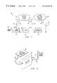
- the object locator system 10includes a two-way paging system 12 , a global positioning satellite system 50 and the object locator 42 .
- the two-way paging system 12is a conventional paging system that is well known in the art, for example, such as illustrated and described in U.S. Pat. No. 5,423,056 issued Jun. 6, 1995 to Lindquist, et al. and entitled ADAPTIVE CELLULAR PAGING SYSTEM, which patent is incorporated by reference herein in its entirety.
- the two-way paging system 12interacts with a base station 18 over a transmit path 14 and a receive path 16 .
- the base station 18may include a telephone, pager, and the like or may have an input 20 for receiving a dialed-in telephone number from telephone set 24 along communications path 22 or from wireless telephone set 25 over communications path 31 .
- Base station 18may, in other embodiments, be aL paging service center in the two-way paging system 12 or a monitoring service coupled with the two-way paging system 12 , instead of a separate operational point of entry for the user to interact with the object locator system 10 of the present disclosure.
- the input 20is responsive to dual tone multi-frequency (DTMF) tones transmitted by telephone set 24 or wireless telephone set 25 .
- Base station 18further has an output 26 from which location data to be displayed travels along path 28 to display 30 .
- DTMFdual tone multi-frequency
- Display 30may be configured to display location information in any of several forms, for example, text, figures, graphics, or numbers.
- the two-way paging system 12may be substituted with a direct RF link or other wireless communication channel.
- the two-way paging system 12is shown in the illustrative embodiment of the present disclosure to represent functionally the concepts of the present disclosure.
- the object locator system 10 of the present disclosureincludes an object locator 42 .
- object locator 42in one of its operational modes, as a two-way paging transceiver, object locator 42 includes an input 40 coupled to an antenna 36 along cable 38 for receiving signals transmitted by two-way paging system 12 along path 32 and for transmitting paging signals to the two-way paging system 12 along path 34 .
- the object locator 42also includes an input 44 for receiving from a global positioning satellite (GPS) system 50 location information signals along path 52 to be intercepted by antenna 48 and conducted to the object locator 42 along path 46 to input 44 .
- GPSglobal positioning satellite
- the global positioning satellite system 50is of a conventional design well known in the art, an example of which is described in U.S. Pat. No.
- location information signalsmay be received from the Glasnost satellite system by the use of a receiving system configured for such reception.
- object locator 42is intended to be carried or attached to an individual, an object or an animal to be located or tracked by the object locator system of the present disclosure.
- a userenters the system from the base station 18 by dialing the telephone number address corresponding to the object locator 42 , which functions as a paging transceiver, for example, on telephone set 24 .
- the telephone number addressmay also be dialed from wireless telephone set 25 and transmitted via RF channel 31 .
- the DTMF signalthen travels along path 22 to input 20 of base station 18 where it is converted to a paging transmit signal and transmitted from antenna 15 along transmit path 14 to the two-way paging system 12 .
- the two-way paging system 12relays the paging message via transmit path 32 to the antenna 36 coupled to the object locator 42 .
- the object locator 42processes the request for location information transmitted by base station 18 , obtains location information from the global positioning satellite system 50 and transmits a response containing the location information from antenna 36 along path 34 to the two-way paging system 12 which, in turn, relays the location information signal along path 16 to antenna 15 of the base station 18 for processing and display on display 30 .
- This relay of the location informationmay occur automatically or in response to a specific inquiry.
- wireless paths 14 and 16 along with antenna 15may instead each comprise a standard telephone connection to a central office.
- a paging centermay dial the phone number of the base station to deliver the location information.
- FIG. 2there is illustrated a pictorial drawing of an object locator 42 as it may be typically configured with a two-way paging antenna 36 and a GPS receive antenna 48 .
- the two-way paging antenna 36is coupled to object locator 42 along cable 38 to an input 40 on the object locator 42 .
- the GPS receive antenna 48is coupled along a cable 46 to an input 44 on the object locator 42 .
- the two-way paging antenna 36 shown in FIG. 2is intended to represent the fact that this antenna in the object locator 42 is typically of the type found with two-way paging equipment. Such an antenna is typically mounted internal to the pager unit itself and is thereby necessarily of very small dimension.
- the object locator 42 of the present disclosuremay be optimized by the use of an external antenna such as shown in FIG. 2 .
- the GPS receive antenna 48is conventionally referred to as a “patch antenna” because of its flat, thin, rectangular shaped design.
- a patch antennais intended to be disposed on an upward, relatively level surface in order to expose it to receive the relatively weak signals transmitted by the global positioning satellite system from the satellites arrayed in the GPS system.
- the illustration in FIG. 2thus demonstrates that both of the antennae used in the system may be positioned for optimal reception and transmission and connected to the object locator 42 using the flexible cables 38 and 46 respectively for the two-way paging antennae 36 and the GPS receive antenna 48 .
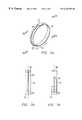
- FIG. 3 a , 3 b and 3 cthere is illustrated a pictorial drawing of an object locator 42 mounted on the lower side of a collar 45 .
- a collar 45is configured for supporting an object locator 42 around the body or neck of an animal which is intended to be tracked or located by the object locator 10 of the present disclosure.
- the GPS antenna 48is attached to the collar diametrically opposite the position of the object locator. This is intentional as will be described hereinbelow.
- the object locatoris coupled to the GPS antenna 48 through a cable 46 which connects to the input 44 of the object locator 42 .
- This arrangementis illustrated in FIG. 3 a and may be more clearly shown by looking at the cross section A-A′ illustrated in FIG.
- Section A-A′a side view of the object locator mounted on a collar is shown wherein collar 45 supports the object locator 42 at its lower point and supports the GPS antenna 48 at its diametrically opposite upper point. As before, the GPS antenna 48 is coupled through cable 46 to input 44 of the object locator 42 .
- a side view identified by cross section B-B′ in FIG. 3 cshows the opposite side of the collar-mounted object locator 42 assembly. In Section B-B′ there is shown the collar 45 which supports the object locator 42 at its lower end and the patch antenna or GPS antenna 48 at its diametrically opposite upper end.
- Section B-B′Also shown in the Section B-B′ is a representation of the two-way paging antenna 36 which is coupled to input 40 of the object locator 42 . It will be appreciated that many configurations are possible for arranging or attaching the object locator and its antennae to the collar 45 , including consolidating the locator and antenna as a unit locatably mounted on or in the collar or, alternatively wherein the locator and antenna is distributively arranged on or in the collar.
- the greater mass of the object locator 42 relative to the mass of the GPS antenna 48 and the fact that they are mounted on diametrically opposite sides of the collar 45enables the object locator 42 to always remain in the lowest possible position and the GPS receiving antenna to always remain in the highest possible position to optimize the reception from the GPS satellite system 50 .
- the mechanismsuch as a clasp or buckle arrangement whereby the collar 45 may be opened and closed to secure the collar around the neck or body of the animal to be tracked or located.
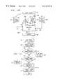
- a paging receiver 60is shown coupling a data output 62 along path 64 to an input of controller 66 .
- Controller 66includes a memory 68 for the storage of location data and a battery 70 for powering the object locator 42 .
- This battery 70is, in the present disclosure, a rechargeable battery.
- This battery 70can be a NiCad battery or a Lithium battery.
- a solar cell 71is provided for charging the battery 70 .
- Controller 66includes a control output 72 which is coupled along path 74 to a control input 76 of paging receiver 60 .
- Paging receiver 60receives paging communications via antenna 36 R which are coupled along cable 38 R to RF input 40 R of paging receiver 60 .
- GPS receiver 78for which provision is made to couple location data at an output 80 along path 82 to an input terminal 84 of controller 66 .
- GPS receiver 78further includes an enable input which is coupled from controller 66 at output 86 along path 88 to the enable input 90 of the GPS receiver 78 .
- the GPS receiver 78receives GPS signals from the global positioning satellite system 50 at antenna 48 which signals are coupled along path 46 to RF input 44 of the GPS receiver 78 .
- GPS receiver 78may be configured for the reception of differential GPS signals to enhance the accuracy of determining the location coordinates.
- a paging transmitter 92which is configured to transmit the location data provided by controller 66 at output 98 along path 96 to the data input 94 of paging transmitter 92 .
- Controller 66also provides an enable output at output 100 along path 102 to the enable input 104 of paging transmitter 92 .
- the paging transmitter 92when enabled, transmits data received at the data input 94 and couples the signal to be transmitted from the output terminal 40 T along path 38 T to the paging transmitter antenna 36 T for radiation to the two-way paging system 12 . It will be appreciated that the paging system components, while shown as separate functional elements in FIG.
- FIG. 4may in fact be integrated into a single two-way paging transceiver which share a common antenna represented by reference number 36 .
- the illustration shown in FIG. 4is intended to provide clarity as to the signal paths that operate during the communication relationship of the object locator 42 with the two-way paging system 12 .
- a number of configurations for coupling the antenna to the paging transceiverare feasible and are also well known in the art and will not be described further herein.
- signal detector 106having an output 108 which is coupled along path 110 to an enable input 112 of controller 66 .
- the signal detector 106represents any of several optional devices which may enable the more precise control of the object locator 42 by limiting the operation of the object locator 42 to certain external conditions outside the paging communications or the GPS reception areas by the object locator 42 .
- the signal detector 106provides an output whenever its detection threshold is crossed by signal energy picked up by antenna 105 from an independent source.
- a signal detector 106may be used to measure the RF signal energy, i.e., the signal field strength noise or the signal-to-voice ratio, for example, that is present at antenna 36 R shown in FIG. 4 .
- Such thresholdmay represent a limiting point beyond which the object locator is enabled to operate e.g., by an electronic fence or, the threshold may represent a distance within which a position of the object locator will probably provide no useful information since the object locator 42 may be within line of sight to the base station, for example. Or, the threshold may be expressed in terms of time or altitude or as an azimuth heading.
- the object locator 42may be programmed for operating an alarm when the object locator 42 moves outside a perimeter.
- Such perimetermay be programmed by physically positioning the object locator 42 at extremes of an area and, while the GPS receiver 78 is operating, storing in the object locator's memory the coordinates reported, thus establishing a boundary outside of which the object locator 42 will automatically report a position. Additionally, the perimeter may be defined by at least one coordinate stored in the object locator memory. The perimeter is then determined by selecting stored algorithms to define the limits of a circular or other geometrical shape outside of which the object locator 42 will automatically report a position.
- each of the major functional blocks shown in FIG. 4may be implemented by means of integrated circuitry which may be configured to fit within a housing of very small dimensions. For example, a pocket pager that typically occupies a volume of approximately three to five cubic inches may weigh approximately four to six ounces.
- the controller 66may comprise a single chip microprocessor or microcontroller or digital signal processor which may be programmed to provide a variety of functions and operational features. Such programs may be stored in memory 68 for use by the controller 66 in controlling the operation of the object locator 42 .
- the paging receiver 60 , the paging transmitter 92 and the GPS receiver 78while shown as functional blocks, in reality, each may have a number of complex finctions incorporated therein.
- the GPS receiver 78 in the object locator 42may be enabled or activated at periodic intervals by a timer (not shown) in the controller 66 . Such periodic activation is useful when operating the object locator 42 as a tracking device or for automatically acquiring and transmitting location information to the paging system 12 or to the base station 18 .
- the GPS receiver 78may be enabled or activated by command from the two-way paging system 12 or from a monitoring service which functions as a base station for a plurality of customers making use of object location services. Such paging system or monitoring service may communicate the location information to a user or a base station by wireless or wired channel means.
- FIG. 5there is illustrated a flowchart for the operation of the object locator 42 shown in FIG. 4 in the case where the user desires to determine the location of the object locator 42 .
- This circumstancemay represent any number of user activities including an owner's efforts to determine the location of a pet dog or a pet cat, for example.
- the operation illustrated in FIG. 5may also include a situation where an owner desires to track versus time, an object to which the object locator 42 is attached.
- the flowchart of FIG. 5may also illustrate the situation when the object locator 42 is attached to a person and it is desired to know the location of that person at some particular time or some other previous time as further described below.
- the flowbegins at block 202 with the start of the sequence of operations, which is followed by decision block 204 in which the object locator 42 seeks to determine whether a page requesting location information has been received by the input 40 of the two-way paging receiver 60 . If the result of this determination is in the negative, then the flow returns to the input of the decision block for a retry. If, however, the result of the query was affirmative, then the flow proceeds to block 206 in which the GPS receiver 78 is enabled to acquire the location coordinates of the object locator 42 by recurring signals from the global positioning satellite system 50 illustrated in FIG. 1 .
- the object locator 42Upon successfully acquiring the coordinates of the object locator 42 and thus of the individual object or animal to which the object locator 42 is attached, the object locator 42 then operates to store the coordinate information in block 208 by loading the coordinate information into the memory 68 of the controller 66 in the object locator 42 .
- coordinate informationmay be associated with a time stamp.
- time stampderived from the GPS satellite system, may then be stored in block 208 for later retrieval.
- coordinate informationmay further be associated with other data for communication to a base station such as object locator operational status, strength of transmitted signals, traversal of a threshold, battery condition, alarm signals and the like.
- the flowthen proceeds from block 208 , where the coordinates were stored in the memory 68 , to block 210 , wherein the object locator 42 is configured to transmit the coordinates in response to the request received over the two-way paging system 12 .
- the transmission of coordinateswill occur in the opposite direction utilizing the same two-way paging system 12 over which the request for location coordinates was received in block 204 .
- the flowproceeds to a timer block 212 which provides a measured interval of time during which the object locator 42 attempts to acquire the coordinates at the particular time from the GPS system 50 .
- a typical GPS systemoften takes a substantial amount of time to acquire location coordinate information from a sufficient number of satellites in order to fix the location of the object locator 42 with a sufficient degree of precision.
- the time requiredinvolves receiving several signals under conditions which may vary widely from instant to instant, which impairs the ability of the GPS receiver 78 as shown in FIG. 4 to obtain complete location data to respond to the request received by the paging receiver 60 in the object locator 42 .
- the time value represented by the timer operating in block 212may be on the order of five to ten minutes, for example. In block 212 , if the timer has not reached the time-out value, then the flow returns to the input of block 206 where the object locator 42 again attempts to acquire the coordinates from the GPS system 50 .
- FIG. 5thus illustrates a basic mode of operation of the object locator 42 . It will be appreciated that many variations on this basic operating mode are possible and may be used to enhance the operation of the object locator 42 . Such features may be programmed into the controller 66 of the object locator 42 .
- FIG. 6there is illustrated a flowchart for the operation of the object locator 42 in the circumstance where it is activated to obtain location information from the GPS receiver 78 only, in this illustrative example, when the object locator 42 is in a position beyond a distance limit relative to the base station or some other defined location from which the request for location coordinates was initiated.
- the flowchart in FIG. 6also shows additional steps in the operational sequence which may be used to enable and disable the GPS receiver 78 within the object locator 42 .
- the GPS receiver 78is typically a device which requires substantial electrical power to operate and so it is to the advantage of the object locator system 10 of the present disclosure to attempt to minimize the power drawn from the object locator battery 70 in FIG. 4 . This may be accomplished by limiting the operating cycle of the GPS receiver 78 to become operational only long enough to obtain the coordinate information that is required by the object locator 42 .
- the flowbegins in FIG. 6 with a start block 220 from which the flow proceeds to a block 222 , wherein the object locator 42 determines whether the object locator 42 is beyond a predetermined limit such as a minimum distance from the base station or other defined location making the request for location information. If the determination is in the negative, that is, the object locator 42 is not beyond the predetermined limit, then the flow returns to the input of the decision block 222 for another attempt. This looping will continue as long as the object locator 42 is within the predetermined limit established by circuitry within the object locator 42 and other portions of the object locator system 10 of the present disclosure. The functional operation of an illustrative example of such a predetermined limit feature will be described further hereinbelow in conjunction with FIG. 7 .
- the flowproceeds from start block 220 to a decision block 222 to determine whether the object locator 42 has received a query from the base stationl 8 . If a query has not been received, the flow proceeds along the “N” path to a timer block 224 wherein the object locator 42 may operate a timed sequence to periodically enable the GPS receiver 78 to acquire location coordinates whether or not a query is received from the base station 18 . When the timer of block 224 times out, the flow proceeds along the “Y” path to a block 226 to enable the GPS receiver 78 .
- decision block, 222if the object locator 42 did receive a query from the base station 18 , the flow proceeds along the “Y” path to block 226 to enable the GPS receiver 78 .
- the flow in the object locator 42proceeds from block 226 to block 228 to acquire the coordinates of the location of the object locator 42 . Thereafter, the flow proceeds to decision block 229 to determine whether the object locator 42 is beyond a predetermined limit with respect to the base station 18 . If the result of the determination in block 229 is negative, the flow proceeds along the “N” path to decision block 231 wherein a counter provides for a predetermined number of trials to establish whether the object locator 42 is beyond the predetermined limit required in block 229 .
- the flowproceeds along the “N” path to re-enter block 228 to acquire location coordinates.
- the flowproceeds along the “Y” path to the input of the decision block 222 .
- the flowproceeds along the “Y” path to block 230 to store the location coordinates acquired from the GPS satellite during the step performed in block 228 , wherein the enable signal applied to the enable terminal 90 thus operates to awaken the GPS receiver 78 so that it may communicate with the GPS system and obtain location information coordinates for the object locator 42 .
- the flowproceeds from block 226 where the GPS receiver 78 is enabled to a block 228 where the object locator 42 acquires the coordinate information from the global positioning satellite system 50 .
- the controller 66 within the object locator 42upon acquiring the coordinates of the object locator 42 from the GPS receiver 78 , the controller 66 within the object locator 42 causes the location information to be stored in the memory 68 of the object locator 42 in the operational block 230 of FIG. 6 .
- the flowthen proceeds to a block 232 where the controller 66 operates to disable the GPS receiver 78 such that it will no longer continue to drain power from the battery, until the next time that it is desired to acquire coordinate information from the GPS system 50 .
- the flowproceeds to a block 234 wherein the object locator 42 provides the location data on output terminal 98 along path 96 to the data input 94 of the paging transmitter 92 .
- the location informationis then transmitted via the two-way paging system 12 to the base station 18 shown in FIG. 1 .
- the flowproceeds from block 234 following the transmission of the coordinate information to a time-out block 236 where a timer provides an interval of time in which the object locator 42 is permitted to acquire the coordinate information from the GPS system, thus maximizing the opportunity to acquire the coordinates before the object locator 42 becomes inactive.
- a timerprovides an interval of time in which the object locator 42 is permitted to acquire the coordinate information from the GPS system, thus maximizing the opportunity to acquire the coordinates before the object locator 42 becomes inactive.
- the time-out valuemay again typically be on the order of five to ten minutes, although the time duration may legitimately be any value that corresponds with the particular circumstances of use and, in fact, may be adjustable in some applications.
- the operationloops back around to the input of the time-out block 236 and enables the object locator 42 to continue attempting to acquire the location information from the GPS system.
- the flowproceeds along the “Y” path from block 236 back to the start of the sequence at the input to the decision block 222 where the object locator 42 is enabled to check whether the object locator 42 is positioned beyond the predetermined limit as previously explained.
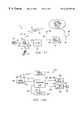
- FIG. 7there is illustrated a pictorial block diagram of one configuration that is possible to provide the predetermined limit signal to the object locator 42 .
- a base station 18coupled with its antenna 126 through a cable 128 and operating to produce a signal which is radiated according to the radiation pattern characteristic of the antenna 126 of the base station.
- an object locator 42which includes a signal detector block 120 coupled to an antenna 122 through a cable 124 . It will be noted that the base station 18 is operating in a transmit mode and the object locator 42 is operating in a receive mode via antenna 122 .
- the object locator 42by comparing the received signal strength of the signal transmitted by the base station from antenna 126 with a reference signal stored within the signal detector 120 , is able to make a determination as to where it is in relation to the base station in terms of the distance that separates the object locator 42 and the base station 18 . It is presumed in this example that the signal strength measured between the base station 18 and the object locator 42 falls off in a predictable manner as compared with the distance that separates the object locator 42 from the base station 18 .
- An alternative to comparing the limit signal with a reference valueis to simply utilize the signal-to-noise characteristics of the receiver in the object locator 42 .
- a limitis thereby provided.
- the limitmay be adjusted simply by adjusting the base station signal strength.
- a predetermined limitmay thus be established by controlling the signal strength of the base station 18 signal such that at an imaginary boundary 130 surrounding base station 18 is defined.
- the signal strengthis of a sufficiently low value which can just be detected by the signal detector 120 in the object locator 42 at the imaginary boundary 130 .
- the object locator 42 antenna 122is greater than a distance indicated by the radius “r” from the base station 18 , then no signal will be detected (or it will be below an acceptable threshold) and the object locator 42 is presumed to be beyond the predetermined limit represented by the distance “r”, which may be thought of as an acceptance radius. If, however, the object locator 42 receives or detects the signal emitted by the base station 18 (or it is above the predetermined threshold), then it is presumed that the antenna 122 of the object locator 42 is within the radius “r” and the object locator 42 must not be, at that point, activated to attempt to acquire location information from the GPS system 50 .
- the base station 302includes a paging receiver 304 which has a receiving antenna 306 coupled to the paging receiver 304 by a cable 308 .
- the output of paging receiver 304is supplied at am output 310 along path 312 to an input 314 of a processor 316 which receives and processes the location information for output or display.
- a processor 316which receives and processes the location information for output or display.
- the informationis stored along a path 318 in a register 320 from which the information can be retrieved along path 322 by the processor 316 for output at terminal 324 along path 326 to the input 328 of a data display 330 .
- the location informationis processed for display as data which may be in the form of degrees of longitude and latitude, the names of the closest major street intersections or in terms of polar coordinates such as an azimuth heading and a distance between the base station 302 and the object locator 42 .
- the location informationmay be translated or converted during the processing operation into voice signals for output as a spoken message via an audio output device (not shown in FIG. 8) or translated or converted into a form for plotting on a map using such means as at least alpha-numeric characters.
- the location informationmay be forwarded from the base station 18 to another remote device or station.
- a base station 350which includes a paging receiver 304 .
- Paging receiver 304receives location information transmitted by object locator 42 to the antenna 306 of the paging receiver 304 along cable 308 .
- Paging receiver 304is coupled from an output 352 along path 354 to an input 356 of processor 358 in the base station 350 .
- Processor 358may also have access to a register 380 along path 378 from which the processor 358 may further obtain stored location information along path 382 from register 380 .
- Such location informationis, of course, available from the GPS receiver 368 via antenna 382 and cable 384 which information is coupled at an output 370 along path 372 to an input 374 to processor 358 .
- This GPS receiver 368is part of base station 350 and enables the base station 350 to provide an enhanced display of the location information obtained from the object locator 42 .
- a GPS display 366that obtains data concerning the location coordinates from processor 358 at an output 360 which flows along path 362 to an input to the GPS display 366 at input 364 .
- the GPS display 366is configured to provide a map of the area that includes both the base station 350 and the object locator 42 , and thus display the relative position of each component of the object locator system 10 with respect to the other.
- a mapmay be shown with streets or thoroughfares indicated thereon and indicia included in the display showing the respective location of the base station 350 and of the object locator 42 .
- Output of location information in the form of alpha-numeric text, spoken messages or map displaysmay be implemented in any of several configurations that may be contemplated. Moreover, provision may be included to enable the user to select which output means is desired. Further, certain outputs of location information may be indicated by or accompanied by an alarm instead of or in addition to the selected output. Further, when the output is, for example, in a text format or a spoken format, the information provided may be used to manually plot the location coordinates on a geographic map of the area in which the object locator 42 is being used.
- the processing of coordinate data produced by the GPS receivermay include translation or conversion of the coordinate data into human readable form by the controller 66 (see FIG. 4) in the object locator 42 prior to the transmission of the location information to the paging system 12 or the base station 18 (see FIG. 1 ).
- the location informationmay be forwarded from the base station 18 to another remote device or station.
- FIG. 10there is shown a flowchart of the operation of the combined units of the object locator system 10 of the present disclosure as illustrated in FIG. 1 .
- the flowbegins at block 402 where the routine starts and thereupon flows to a block 404 in which the base station 18 requests location information by paging the object locator 42 .
- the base station 18transmits a request for location information to the object locator 42 .
- the flowproceeds from block 404 to block 412 where the object locator 42 proceeds through the sequence to enable the GPS receiver 78 in order to obtain new location coordinate information.
- the object locator 42checks its own memory—see, for example, the block diagram of the object locator 42 shown in FIG.
- the flowproceeds to a block 424 wherein the base station 18 makes a determination as to whether it has received the requested coordinate information from the object locator 42 . If the result is affirmative, then the flow proceeds along the “Y” path to a block 428 where the base station 18 proceeds to output or display the coordinate information to the user at the base station 18 . Thereupon, the flow proceeds from block 428 to a block 430 wherein the routine ends.
- the base station 18determines whether it did not receive the coordinate information as requested, then the flow proceeds to block 426 along the “N” path to a decision block 426 .
- the base station 18determines whether the most recent page of the object locator 42 was, in fact, the last attempt permitted within the protocol for the base station operation. If the result is affirmative, then the flow proceeds along the “Y” path to block 418 where the object locator 42 operates to disable the GPS receiver 78 so that it no longer uses power from the battery 70 of the object locator 42 and thereafter proceeds to block 430 where the routine ends. If, however, the result of the determination in block 426 was negative, then the flow returns to the start of the routine at the input to block 404 where the base station 18 re-attempts to page the object locator 42 .
- the object locator 42checks to determine whether location coordinate information is, in fact, in the memory 68 of the object locator 42 . If the result is negative, the flow proceeds along the “N” path to block 414 where the object locator 42 acquires the new coordinate information and, as previously described, proceeds in block 416 to store the new coordinate information in memory 68 of the object locator 42 . The flow then returns to the input of block 412 wherein the GPS receiver 78 is enabled.
- the above noted object location systemwas disclosed as being utilized in conjunction with a pet, such that the pet owner can determine the location of their wayward pet.
- the locatoras described hereinabove, in one embodiment, is triggered to determine the location of the pet in response to receiving a signal from a paging system.
- the paging systemutilizes existing infrastructure in order to direct a message over a wireless link to a moving object, such as the pet. This only requires the inclusion of a paging receiver tuned to the frequency of the paging transmitters. Of course, there are multiple paging transmitters disposed about any given area. If the pet wandered outside of the range of all of these paging transmitters, then the system will not work. This would then, in the alternative, require a direct RF link to the pet.
- the locator 42will do one of two things. First, it could merely search its own memory to determine if location coordinates are stored therein from a previous acquisition operation of the GPS system. If so, these could be transmitted back to the requester. Alternatively the GPS system is turned on in response to receiving the request and then the location determined. Of course, as described hereinabove, there are provisions made for situations wherein the GPS system cannot be acquired.
- the disclosed embodimentsets forth the use of a two-way pager.
- These two-way pagersare desirable in that they make use of the existing infrastructure of the paging system. This is facilitated by the inclusion of a plurality of receivers at each of the paging towers or paging “sticks” which allow the signal to be received and forwarded back to a central station. This central station then processes the information received and forwards it to the user.
- This informationis in the form of coordinates. This coordinate information can then be relayed back to the user in any number of ways. It could actually be forwarded via a paging channel to the user, which might result in a latency of approximately two to five minutes.
- the two-way system that can be utilizedis a conventional system, one example of such a conventional system described in U.S. Pat. No. 5,708,971, issued Jan. 13, 1998, and entitled “TWO-WAY PAGING SYSTEM AND APPARATUS, which is incorporated herein by reference.
- the object locator system 11includes a base station 18 , an object locator 42 and a global positioning satellite system 50 .
- the base station 18 and the object locator 42communicate directly with each other over a wireless link shown by the pair of arrows, arrow 21 and arrow 23 .
- This wireless link 21 , 23will be described further hereinbelow.
- the base station 18may include a telephone, pager and the like or may have an input 20 for receiving a dialed-in telephone number from a telephone set 24 along communications path 22 or from a wireless telephone set 25 over communications path : 31 .
- the input 20is responsive to dual-tone multi-frequency (DTMF) tones transmitted by telephone set 24 or wireless telephone set 25 .
- Base station 18further has an output 26 from which location data to be displayed travels along path 28 to display 30 .
- Display 30may be configured to display location information in any of several forms, for example, text, figures, graphics, or numbers. In a typical graphics display, a map of the region in which the object locator 42 is operating may be displayed with the location coordinates for the object locator displayed on the map reproduced on display 30 .
- the wireless link 21 , 23may be any radio frequency communications channel operable between two stations such as a direct RF link in a system having a base station and a mobile station and not requiring an intermediate station to relay transmissions between the base and mobile stations.
- the wireless link 21 , 23may utilize satellite communications to link together the object locator 42 and the base station 18 shown in FIG. 11 .
- the antenna 15 and 36 and their associated transmit and receive structuresare, of course, configured for satellite communications which will then occur as represented by wireless link 21 , 23 .
- the wireless links 21 , 23may be implemented by numerous alternative means that are well known in the art and will not be described further.
- One example, shown in the illustrative embodiment of FIG. 1utilizes a two-way paging system to provide the RF or wireless link between the base station 18 and the object locator 42 .
- the object locator system 11 of the present disclosureincludes an object locator 42 .
- the object locator 42includes an input 40 coupled to an antenna 36 along cable 38 for receiving signals transmitted in the wireless link from the base station 18 .
- the object locator 42also includes an input 44 for receiving location information signals from a global positioning satellite (GPS) system 50 via the RF path 52 and intercepted by antenna 48 . From antenna 48 , the GPS signals are conducted to the object locator 42 along path 46 to input 44 .
- GPS system 50is of a conventional design well known in the art, illustratively described in U.S. Pat. No. 5,726,660 issued Mar. 10, 1998 to Purdy, et al.
- location information signalsmay be received from the Glasnost Satellite System by the use of a receiving system configured for such reception.
- object locator 42is intended to be carried or attached to an individual, an object or an animal to be located or tracked by the object locator system 11 of the present disclosure.
- a userenters the system from the base station, for example, 18 by dialing the telephone number address corresponding to the object locator 42 .
- the object locator 42functions as a receiver for receiving requests or instructions along wireless link 23 or as a transmitter of location information along wireless link 21 to the base station 18 .
- the telephone numbermay be dialed on telephone set 24 or telephone set 25 .
- the DTMF signal generated by the telephone set 24 or 25is coupled by path 22 to input 20 of base station 18 .
- the DTMF request signalis converted to a wireless signal and transmitted from antenna 15 along transmit path 23 to the antenna 36 coupled to object locator 42 along cable 38 .
- the object locator 42processes the request for location information transmitted by base station 18 , obtains location information from the global positioning satellite system 50 and transmits a response containing the location information from antenna 36 along path 21 to the antenna 15 coupled to base station 18 for processing and display on display 30 .
- specific structural components of a standard telephone channel, adapted for the purposemay be substituted for the wireless paths 21 and 23 , along with antenna 15 and antenna 36 and their related structures.
- the base station 302includes a paging receiver 304 which has a receiving antenna 306 coupled to the paging receiver 304 by a cable 308 .
- the output of paging receiver 304is supplied in an output 310 along path 312 to an input 314 of a processor 316 which receives and processes the location information for output or display.
- the informationis stored via path 318 in a register 320 .
- the informationmay be retrieved via path 322 by the processor 316 for processing prior to being output at terminal 324 along path 326 to the input 328 of a data display 330 .
- the location informationis processed for display as data which may be in the form of degrees of longitude and latitude, the names of the closest major street intersections, as indicia of the object locator 42 and the base station 18 or in terms of polar coordinates such as an asimuth heading and a distance between the base station 302 and the object locator 42 .
- the location informationmay be translated or converted into a form for plotting on a map reproduced on display 330 .
- the location informationmay be translated or converted during the processing operation into voice signals for output as a spoken message via an audio output 338 shown in FIG. 12 a .
- the audio output 338receives location information translated or converted into voice signals from output 332 along line 334 to input 336 of audio output 338 .
- Audio output 338may typically be an audio power amplifier for generating an audio signal with sufficient power to drive a loudspeaker, for example. In other embodiments, such audio output 338 may be configured as a line output to drive a voice mail system, a telephone connection or other audio output means. From the audio output 338 , in this illustrative example, the voice or audio signal is coupled along line 340 to loud speaker 342 for playback to the user.
- certain annunciating signals indicative of an alarm condition as described hereinabovemay also be coupled along line 334 to audio output 338 for playback by loudspeaker 342 or by an alarm transducer configured for the purpose.
- the base station 351includes a paging receiver 304 .
- Paging receiver 304receives location information transmitted by object locator 42 to the antenna 306 of the paging receiver 304 along cable 308 .
- the output of paging receiver 304is coupled from an output 352 along path 354 to an input 356 of processor 358 in the base station 351 .
- Processor 358may also have access to a register 380 along path 378 from which the processor 358 may further obtain stored location information along path 382 from register 380 .
- Such location informationis, of course, available from the GPS receiver 368 via antenna 396 coupled to GPS receiver 368 along cable 338 .
- the location informationthen, is coupled at an output 370 from GPS receiver 368 along path 372 to an input 374 to processor 358 .
- This GPS receiver 368is part of base station 351 and enables the base station 351 to provide an enhanced display of the location information obtained from the object locator 42 .
- This enhanced displaymay include the presentation of a map of the region in which the object locator 42 is to be operated.
- GPS display 366which is the enhanced display referred to in the preceding paragraph, that obtains data concerning the location coordinates from processor 358 at an output 360 which flows along path 362 to an input to the GPS display 366 at input 364 .
- the GPS display 366is configured to provide a map of the area that includes both the base station 351 and the object locator 42 , and thus may display the relative position of each component of the object locator system 10 with respect to the other.
- audio output 390which is operable to receive voice signals or other audio frequency signals at input 388 via line 386 from output 384 of processor 358 , such signals resulting from translation or conversion of the location information during the processing operation in processor 358 .
- Audio output 390prepares the audio signals for driving loudspeaker 394 via line 392 .
- certain annunciating signals indicative of an alarm conditionmay also be coupled along line 386 to audio output 390 for playback by loudspeaker 394 .
- Audio output 390may typically be an audio power amplifier for generating an audio signal with sufficient power to drive a loudspeaker as described hereinabove. In other embodiments such audio output may be configured as a line output to drive a voice mail system, a telephone connection or other audio means.
- FIGS. 12 a and 12 bmay also implement the object locator system 11 of FIG. 11 merely by substituting some other wireless link for the paging system and paging receiver 304 shown in FIG. 12 a and 12 b .
- a mapmay be shown with streets and thoroughfares indicated thereon and indicia included in a display showing the respective location of the base station 350 and of the object locator 42 .
- readout statementsproviding street names, longitude, latitude, azimuth or distance may also be included in the displayed output.
- FIGS. 12 a and 12 bare intended to be illustrative and not limited to the specific embodiments illustrating the concepts and principles of the present disclosure.
- Output of location information in the form of alpha-numeric text, spoken messages or map displaysmay be implemented in any of the several configurations that may be contemplated.
- provision for including several different output structures as illustrated in FIG. 12 a and 12 b and for enabling the user to select which output means is desiredmay also be incorporated in the systems illustrated hereinabove. Certain outputs of location information may be indicated by or accompanied by an alarm instead of or in addition to the selected output.
- the information providedmay be used to manually plot the location coordinates on a geographic map of the area in which the object locator 42 is being used.
- the processing of coordinate data produced by the GPS receivermay include translation or conversion of the coordinate data into human readable form by the controller 66 (see FIG. 4) in the object locator 42 prior to the transmission of the location information from the object locator 42 to the base station 18 (see FIG. 1 ).
- FIG. 13illustrates just two cases where the object locator 42 is operable to associate other information related to the operation of the object locator system 10 with the location coordinate information in order to enhance the functionality of the object locator system 10 .
- the examples in FIG. 13illustrate associating information about battery condition or relation of the object locator to a boundary or a threshold with the location coordinate information that can be transmitted from the object locator 42 to the base station 18 . It will be observed by inspection of FIG. 13 that the flow begins at block 404 and continued through block 412 which blocks respectively also appear in FIG. 10 as consecutive blocks in the flowchart following the start block at 402 .
- the object locator 42receives the page from base station 18 .
- the object locator in decision block 407performs a test of the battery 70 to determine whether or not there is sufficient battery capacity to proceed with the acquisition of location coordinate information from the GPS system 50 . If the battery test indicates that sufficient battery capacity exists, then the flow proceeds along the “Y” path to decision block 411 where the object locator 42 performs a second test to determine whether or not a threshold has been traversed.
- the object locator 42may be within or beyond a predetermined range established by the strength of a signal being transmitted from the base station 18 or by the receipt of a signal indicating traversal of the boundary of an electronic fence.
- the flowproceeds along the “Y” path to block 412 to enable the GPS receiver 78 in the object locator 42 . Thereupon the flow proceeds to the steps of the flowchart as illustrated in FIG. 10 .
- the flowproceeds along the “N” path to block 409 where the controller 66 (see FIG. 4) in the object locator 42 will proceed to fetch the alarm byte for a low battery to indicate that the battery 70 has insufficient capacity.
- This low-battery test alarm byteis provided to the transmitter in the object locator 42 and, as shown in block 415 , the object locator 42 is operable to transmit this alarm byte to the base station 18 .
- the flowproceeds from block 415 to block 417 where the routine ends.
Landscapes
- Engineering & Computer Science (AREA)
- Radar, Positioning & Navigation (AREA)
- Remote Sensing (AREA)
- Physics & Mathematics (AREA)
- General Physics & Mathematics (AREA)
- Computer Networks & Wireless Communication (AREA)
- Signal Processing (AREA)
- Position Fixing By Use Of Radio Waves (AREA)
- Mobile Radio Communication Systems (AREA)
Abstract
Description
Claims (59)
Priority Applications (7)
| Application Number | Priority Date | Filing Date | Title |
|---|---|---|---|
| US09/362,789US6236358B1 (en) | 1999-06-18 | 1999-07-28 | Mobile object locator |
| PCT/US2000/016009WO2000079703A1 (en) | 1999-06-18 | 2000-06-09 | Mobile object locator |
| AU56046/00AAU5604600A (en) | 1999-06-18 | 2000-06-09 | Mobile object locator |
| US09/862,569US6518919B1 (en) | 1999-06-18 | 2001-05-22 | Mobile object locator |
| US10/361,802US6859171B2 (en) | 1999-06-18 | 2003-02-10 | Mobile object locator |
| US11/063,254US7209075B2 (en) | 1999-06-18 | 2005-02-22 | Mobile object locator |
| US11/789,053US7760137B2 (en) | 1999-06-18 | 2007-04-23 | Portable position determining device |
Applications Claiming Priority (2)
| Application Number | Priority Date | Filing Date | Title |
|---|---|---|---|
| US14004099P | 1999-06-18 | 1999-06-18 | |
| US09/362,789US6236358B1 (en) | 1999-06-18 | 1999-07-28 | Mobile object locator |
Related Child Applications (1)
| Application Number | Title | Priority Date | Filing Date |
|---|---|---|---|
| US09/862,569ContinuationUS6518919B1 (en) | 1999-06-18 | 2001-05-22 | Mobile object locator |
Publications (1)
| Publication Number | Publication Date |
|---|---|
| US6236358B1true US6236358B1 (en) | 2001-05-22 |
Family
ID=26837820
Family Applications (4)
| Application Number | Title | Priority Date | Filing Date |
|---|---|---|---|
| US09/362,789Expired - Fee RelatedUS6236358B1 (en) | 1999-06-18 | 1999-07-28 | Mobile object locator |
| US09/862,569Expired - Fee RelatedUS6518919B1 (en) | 1999-06-18 | 2001-05-22 | Mobile object locator |
| US10/361,802Expired - Fee RelatedUS6859171B2 (en) | 1999-06-18 | 2003-02-10 | Mobile object locator |
| US11/063,254Expired - Fee RelatedUS7209075B2 (en) | 1999-06-18 | 2005-02-22 | Mobile object locator |
Family Applications After (3)
| Application Number | Title | Priority Date | Filing Date |
|---|---|---|---|
| US09/862,569Expired - Fee RelatedUS6518919B1 (en) | 1999-06-18 | 2001-05-22 | Mobile object locator |
| US10/361,802Expired - Fee RelatedUS6859171B2 (en) | 1999-06-18 | 2003-02-10 | Mobile object locator |
| US11/063,254Expired - Fee RelatedUS7209075B2 (en) | 1999-06-18 | 2005-02-22 | Mobile object locator |
Country Status (1)
| Country | Link |
|---|---|
| US (4) | US6236358B1 (en) |
Cited By (128)
| Publication number | Priority date | Publication date | Assignee | Title |
|---|---|---|---|---|
| US6363320B1 (en)* | 2000-08-18 | 2002-03-26 | Geospatial Technologies Inc. | Thin-client real-time interpretive object tracking system |
| US20020055817A1 (en)* | 2000-08-18 | 2002-05-09 | Yue-Hong Chou | Real-time smart mobile device for location information processing |
| US20020114626A1 (en)* | 2001-02-09 | 2002-08-22 | Seiko Epson Corporation | Service providing system, management terminal, mobile member, service providing program, and service providing method |
| US20020177476A1 (en)* | 2001-05-22 | 2002-11-28 | Chou Y. Hong | Durable global asset-tracking device and a method of using the same |
| US20020196151A1 (en)* | 2000-12-26 | 2002-12-26 | Troxler Robert Ernest | Large area position/proximity correction device with alarms using (D)GPS technology |
| WO2003005316A1 (en)* | 2001-07-03 | 2003-01-16 | Time N Space Technology, Inc. | Animal collar |
| US20030060212A1 (en)* | 2000-02-28 | 2003-03-27 | Invention Depot, Inc. | Method and system for location tracking |
| US6559620B2 (en) | 2001-03-21 | 2003-05-06 | Digital Angel Corporation | System and method for remote monitoring utilizing a rechargeable battery |
| US20030144892A1 (en)* | 2002-01-29 | 2003-07-31 | International Business Machines Corporation | Method, system, and storage medium for providing knowledge management services |
| US20030149526A1 (en)* | 2001-10-29 | 2003-08-07 | Zhou Peter Y | Systems and methods for monitoring and tracking related U.S. patent applications |
| US20030179140A1 (en)* | 2002-03-19 | 2003-09-25 | Patterson Wade C. | Apparatus and method for keeping pets in a defined boundary having exclusion areas |
| US20030201931A1 (en)* | 1999-06-18 | 2003-10-30 | Jennifer Durst | Mobile object locator |
| US20030231163A1 (en)* | 2002-06-13 | 2003-12-18 | Kris Hanon | Interface for a multifunctional system |
| US6674368B2 (en) | 2000-08-28 | 2004-01-06 | Continental Divide Robotics, Inc. | Automated tracking system |
| US20040012519A1 (en)* | 1999-06-18 | 2004-01-22 | Jennifer Durst | Portable position determining device |
| US6693585B1 (en) | 2002-02-07 | 2004-02-17 | Aradiant Corporation | Self-contained selectively activated mobile object position reporting device with reduced power consumption and minimized wireless service fees. |
| US20040046658A1 (en)* | 2002-08-08 | 2004-03-11 | Jon Turner | Dual watch sensors to monitor children |
| US6720879B2 (en)* | 2000-08-08 | 2004-04-13 | Time-N-Space Technology, Inc. | Animal collar including tracking and location device |
| US20040073363A1 (en)* | 2002-07-23 | 2004-04-15 | Eliezer Sanchez | Electronic localizing protection device |
| US20040113772A1 (en)* | 2002-12-11 | 2004-06-17 | Y. Hong Chou | Method and apparatus for an automated location-based, dynamic notification system ( ALDNS) |
| US20040137938A1 (en)* | 2002-12-20 | 2004-07-15 | Deubler Donald L. | Method and system for emergency dialing of a wireless communication device |
| USD496638S1 (en) | 2003-11-12 | 2004-09-28 | Firefly Mobile, Inc. | Cellular telephone |
| USD496639S1 (en) | 2003-11-12 | 2004-09-28 | Firefly Mobile, Inc. | Cellular telephone |
| WO2004097447A1 (en)* | 2003-04-29 | 2004-11-11 | Telenor Asa | A system and a method for managing the power consumption of a tracking device |
| US6825767B2 (en) | 2002-05-08 | 2004-11-30 | Charles Humbard | Subscription system for monitoring user well being |
| US20040239563A1 (en)* | 2003-05-30 | 2004-12-02 | Jocher Ronald W. | Discrete radiation source location |
| US6850188B1 (en)* | 2002-04-05 | 2005-02-01 | Garmin Ltd. | Combined global positioning system receiver and radio with enhanced display features |
| US20050032504A1 (en)* | 2003-08-08 | 2005-02-10 | Camp R. Allen Van | Methods and apparatus for communication |
| US20050073409A1 (en)* | 1999-06-18 | 2005-04-07 | Jennifer Durst | Object locator |
| US20050088301A1 (en)* | 2003-10-14 | 2005-04-28 | Paul Abbruscato | Direction finder and locator |
| US6889135B2 (en) | 1999-03-31 | 2005-05-03 | C2 Global Technologies, Inc. | Security and tracking system |
| US6903682B1 (en) | 2004-01-14 | 2005-06-07 | Innotek, Inc. | DGPS animal containment system |
| US20050136912A1 (en)* | 1999-03-31 | 2005-06-23 | Curatolo Benedict S. | Security and tracking system |
| USD508028S1 (en) | 2003-11-12 | 2005-08-02 | Firefly Mobile, Inc. | Cellular telephone |
| US20050177416A1 (en)* | 1999-12-09 | 2005-08-11 | Linden Craig L. | Mobile advertising methods and improvements |
| US6975941B1 (en) | 2002-04-24 | 2005-12-13 | Chung Lau | Method and apparatus for intelligent acquisition of position information |
| WO2006024298A1 (en)* | 2004-08-30 | 2006-03-09 | Kidspotter A/S | System and method for determining a position of an object |
| GB2419057A (en)* | 2004-10-06 | 2006-04-12 | Alison Maclennan | Device for locating moveable property or goods comprising a GSM and a GPS module |
| US7034747B1 (en) | 2002-11-07 | 2006-04-25 | Garmin Ltd. | System and method for wirelessly linking a GPS device and a portable electronic device |
| US20060099959A1 (en)* | 2004-11-05 | 2006-05-11 | Houston Staton | Method and system to monitor movable entities |
| US20060099971A1 (en)* | 2004-11-05 | 2006-05-11 | Houston Staton | Method and system to monitor and control devices utilizing wireless media |
| US20060099969A1 (en)* | 2004-11-05 | 2006-05-11 | Houston Staton | Method and system to monitor persons utilizing wireless media |
| US20060202818A1 (en)* | 2005-03-09 | 2006-09-14 | Greenberg Stephen J | Pet tracking systems, other tracking systems, and portable virtual fence |
| US20060234726A1 (en)* | 2005-04-13 | 2006-10-19 | Wirelesswerx International, Inc. | Method and System for Initiating and Handling an Emergency Call Utilizing Geographical Zones |
| US20060233318A1 (en)* | 2005-04-13 | 2006-10-19 | Wirelesswerx International, Inc. | Method and System for Providing Location Updates |
| US20060234727A1 (en)* | 2005-04-13 | 2006-10-19 | Wirelesswerx International, Inc. | Method and System for Initiating and Handling an Emergency Call |
| US20060258285A1 (en)* | 2005-05-11 | 2006-11-16 | Riddles Philip J | Enabling desired wireless connectivity in a high frequency wireless local area network |
| US7142900B1 (en) | 2001-11-01 | 2006-11-28 | Garmin Ltd. | Combined global positioning system receiver and radio |
| US20070015517A1 (en)* | 2005-07-12 | 2007-01-18 | Qwest Communications International Inc. | Location related keyword monitoring on a mobile communications device systems and methods |
| US20070015520A1 (en)* | 2005-07-12 | 2007-01-18 | Qwest Communications International Inc. | Efficiently determining the location of a mobile communications device system and methods |
| US20070015519A1 (en)* | 2005-07-12 | 2007-01-18 | Qwest Communications International Inc. | User defined location based notification for a mobile communications device systems and methods |
| US20070015521A1 (en)* | 2005-07-12 | 2007-01-18 | Qwest Communications International Inc. | Correlating activities with the location of a mobile communications device systems and methods |
| US20070013560A1 (en)* | 2005-07-12 | 2007-01-18 | Qwest Communications International Inc. | Mapping the location of a mobile communications device systems and methods |
| USD538191S1 (en) | 2004-09-07 | 2007-03-13 | Wilder Otis T | Personal tracking and location device |
| US7196659B1 (en) | 1999-05-07 | 2007-03-27 | Garmin Corporation | Combined global positioning system receiver and radio |
| US7212829B1 (en) | 2000-02-28 | 2007-05-01 | Chung Lau | Method and system for providing shipment tracking and notifications |
| US7218938B1 (en) | 2002-04-24 | 2007-05-15 | Chung Lau | Methods and apparatus to analyze and present location information |
| WO2007089694A2 (en) | 2006-01-30 | 2007-08-09 | Overby Farm, Llc | Companion animal convenience center |
| US20070247359A1 (en)* | 2006-04-25 | 2007-10-25 | Ghazarian Ohanes D | Automatic GPS tracking system with passive battery circuitry |
| US20070279165A1 (en)* | 2003-02-19 | 2007-12-06 | Gilmore Glendell N | Reed Switch Apparatus and Method of Using Same |
| US7308272B1 (en) | 2001-10-25 | 2007-12-11 | On-Board Communications, Inc. | Mobile phone locator |
| US20070290866A1 (en)* | 2006-06-19 | 2007-12-20 | Bily Wang | Real-time tracing, transmitting and analyzing system for flight animals |
| US20080004798A1 (en)* | 2000-12-26 | 2008-01-03 | Troxler Electronic Laboratories, Inc. | Methods, systems, and computer program products for locating and tracking objects |
| US7321774B1 (en) | 2002-04-24 | 2008-01-22 | Ipventure, Inc. | Inexpensive position sensing device |
| US7330150B1 (en) | 1999-05-07 | 2008-02-12 | Garmin Corporation | Combined global positioning system receiver and radio |
| USD561730S1 (en) | 2007-03-09 | 2008-02-12 | Firefly Mobile, Inc. | Cellular telephone |
| US20080036610A1 (en)* | 2006-08-08 | 2008-02-14 | Garmin Ltd. | Animal tracking apparatus and method |
| USD562300S1 (en) | 2007-03-09 | 2008-02-19 | Firefly Mobile, Inc. | Cellular telephone |
| US20080055155A1 (en)* | 2006-08-29 | 2008-03-06 | Hensley Charles R | Object identity and location tracking system |
| US20080126007A1 (en)* | 2004-08-04 | 2008-05-29 | S.A.E. Afikim Computerized Dairy Management System | Method and a System for Locating Objects in a Defined Area |
| US20080129184A1 (en)* | 2006-12-05 | 2008-06-05 | Semiconductor Energy Laboratory Co., Ltd. | Plasma display panel and field emission display |
| US7403972B1 (en) | 2002-04-24 | 2008-07-22 | Ip Venture, Inc. | Method and system for enhanced messaging |
| US20080186176A1 (en)* | 2007-02-06 | 2008-08-07 | Sony Corporation | System and method for effectively determining a physical location of a remote control device |
| US20080220720A1 (en)* | 2004-11-05 | 2008-09-11 | Wirelesswerx International, Inc. | Method and system for providing area specific messaging |
| US20080246656A1 (en)* | 2006-04-25 | 2008-10-09 | Ghazarian Ohanes D | Automatic GPS tracking system with passive battery circuitry |
| US20080262780A1 (en)* | 2002-10-11 | 2008-10-23 | Troxler Electronic Laboratories, Inc. | Paving-Related Measuring Device Incorporating a Computer Device and Communication Element Therebetween and Associated Method |
| US20090132163A1 (en)* | 2007-08-30 | 2009-05-21 | Wirelesswerx International, Inc. | Configuring and using multi-dimensional zones |
| US20090137255A1 (en)* | 2007-08-30 | 2009-05-28 | Wirelesswerx International, Inc. | Mapping in a multi-dimensional space |
| US20090138336A1 (en)* | 2007-08-30 | 2009-05-28 | Wirelesswerx International, Inc. | Messaging in a multi-dimensional space |
| US20090150003A1 (en)* | 2007-11-16 | 2009-06-11 | Jordan B Delano | Turf Irrigation System |
| US20100127919A1 (en)* | 2008-11-21 | 2010-05-27 | Zoombak Llc | Geo-Fence With Minimal False Alarms |
| US20100164712A1 (en)* | 2004-12-09 | 2010-07-01 | Dean John William Corrigan | Communications system |
| US20100185524A1 (en)* | 2003-10-03 | 2010-07-22 | General Motors Corporation | Telematics unit and method for operating |
| US20100223063A1 (en)* | 2009-02-27 | 2010-09-02 | Myatt Andrew J | Radio Device and Methods of Supplying Same |
| US20100225472A1 (en)* | 2003-08-01 | 2010-09-09 | Culpepper Jerry W | Method and system for providing tracking services to locate an asset |
| US7845313B1 (en)* | 2008-05-12 | 2010-12-07 | Yates Corey D | Device for storing and protecting pet medical data, particularly suited for being carried by a pet |
| US7864057B2 (en) | 2006-09-13 | 2011-01-04 | Perfectech, Inc. | Pet locating device |
| US7925320B2 (en) | 2006-03-06 | 2011-04-12 | Garmin Switzerland Gmbh | Electronic device mount |
| US8200186B2 (en) | 2007-08-30 | 2012-06-12 | Wirelesswerx International, Inc. | Emergency control in a multi-dimensional space |
| US8239169B2 (en) | 2009-09-25 | 2012-08-07 | Gregory Timothy L | Portable computing device and method for asset management in a logistics system |
| US8299920B2 (en) | 2009-09-25 | 2012-10-30 | Fedex Corporate Services, Inc. | Sensor based logistics system |
| US8612278B1 (en) | 2013-03-06 | 2013-12-17 | Wirelesswerx International, Inc. | Controlling queuing in a defined location |
| US20140085084A1 (en)* | 2012-09-27 | 2014-03-27 | Loran Technologies, Inc | Passive active battery saver tracking system |
| US8976951B1 (en) | 2004-12-06 | 2015-03-10 | Callwave Communications, Llc | Methods and systems for telephony call-back processing |
| US8994591B2 (en) | 1996-09-09 | 2015-03-31 | Tracbeam Llc | Locating a mobile station and applications therefor |
| US9049571B2 (en) | 2002-04-24 | 2015-06-02 | Ipventure, Inc. | Method and system for enhanced messaging |
| US9060341B2 (en) | 1996-09-09 | 2015-06-16 | Tracbeam, Llc | System and method for hybriding wireless location techniques |
| US9134398B2 (en) | 1996-09-09 | 2015-09-15 | Tracbeam Llc | Wireless location using network centric location estimators |
| US9182238B2 (en) | 2002-04-24 | 2015-11-10 | Ipventure, Inc. | Method and apparatus for intelligent acquisition of position information |
| US20160005282A1 (en)* | 2005-07-27 | 2016-01-07 | Empire Ip Llc | Anti-Theft Security Device and Perimeter Detection System |
| US9253319B1 (en) | 2005-07-01 | 2016-02-02 | Callwave Communications, Llc | Methods and systems for call connecting calls |
| US9413885B1 (en) | 2006-10-06 | 2016-08-09 | Callwave Communications, Llc | Methods and systems for blocking unwanted communications |
| US9467968B2 (en) | 2013-10-07 | 2016-10-11 | Ickovic & Bliss, Inc. | Wearable mobile broadcasting recovery system and device |
| US9538493B2 (en) | 2010-08-23 | 2017-01-03 | Finetrak, Llc | Locating a mobile station and applications therefor |
| US9633327B2 (en) | 2009-09-25 | 2017-04-25 | Fedex Corporate Services, Inc. | Sensor zone management |
| US9736618B1 (en) | 2005-04-04 | 2017-08-15 | X One, Inc. | Techniques for sharing relative position between mobile devices |
| US9875492B2 (en) | 2001-05-22 | 2018-01-23 | Dennis J. Dupray | Real estate transaction system |
| US9961884B1 (en) | 2013-03-15 | 2018-05-08 | GPSip, Inc. | Wireless location assisted zone guidance system compatible with large and small land zones |
| US10064390B1 (en) | 2013-03-15 | 2018-09-04 | GPSip, Inc. | Wireless location assisted zone guidance system incorporating a multi-zone containment area |
| US10080346B2 (en) | 2013-03-15 | 2018-09-25 | GPSip, Inc. | Wireless location assisted zone guidance system |
| US10165755B1 (en) | 2013-03-15 | 2019-01-01 | GPSip, Inc. | Wireless location assisted zone guidance system region lookup |
| US10165756B1 (en) | 2014-03-18 | 2019-01-01 | GPSip, Inc. | Wireless location assisted zone guidance system incorporating a rapid collar mount and non-necrotic stimulation |
| US10172325B1 (en) | 2013-03-15 | 2019-01-08 | GPSip, Inc. | Wireless location assisted zone guidance system incorporating dynamically variable intervals between sequential position requests |
| US10251371B1 (en)* | 2014-03-18 | 2019-04-09 | GPSip, Inc. | Wireless location assisted zone guidance system incorporating a system and apparatus for predicting the departure of an animal from a safe zone prior to the animal actually departing |
| US10292365B1 (en) | 2013-03-15 | 2019-05-21 | GPSip, Inc. | Wireless location assisted zone guidance system incorporating shepherding of wayward dogs |
| US10342218B1 (en) | 2013-03-15 | 2019-07-09 | GPSip, Inc. | GPS dog fence incorporating location guidance and positive reinforcement training |
| US10388080B2 (en) | 2000-08-31 | 2019-08-20 | Strategic Design Federation W, Inc. | Automobile monitoring for operation analysis |
| US10470437B1 (en) | 2013-03-15 | 2019-11-12 | GPSip, Inc. | Wireless location assisted zone guidance system |
| US10624319B2 (en) | 2014-03-18 | 2020-04-21 | GPSip, Inc. | Wireless location assisted zone guidance system incorporating a rapid collar mount and non-necrotic stimulation |
| US10641861B2 (en) | 2000-06-02 | 2020-05-05 | Dennis J. Dupray | Services and applications for a communications network |
| US10684350B2 (en) | 2000-06-02 | 2020-06-16 | Tracbeam Llc | Services and applications for a communications network |
| WO2020142089A1 (en) | 2018-12-31 | 2020-07-09 | GPSip, Inc. | Wireless location assisted zone guidance system incorporating a rapid collar mount and non-necrotic stimulation |
| USD901097S1 (en) | 2018-09-19 | 2020-11-03 | Christopher Coughlan | Dog garment |
| CN112119321A (en)* | 2018-05-23 | 2020-12-22 | 利拉伐控股有限公司 | System, method and computer program for locating animal tags |
| WO2021055883A2 (en) | 2019-09-18 | 2021-03-25 | GPSip, Inc. | Wireless location assisted zone guidance system incorporating secure transmission of location |
| US11713968B2 (en) | 2018-03-17 | 2023-08-01 | GPSip, Inc. | Wireless location assisted zone guidance system incorporating secure transmission of location |
| US11778420B2 (en) | 2020-06-29 | 2023-10-03 | Ickovic & Bliss, Inc. | Systems, methods, and program products for digital PET identification |
| US12171192B1 (en) | 2022-02-14 | 2024-12-24 | GPSip, Inc. | Graphical shepherding |
Families Citing this family (114)
| Publication number | Priority date | Publication date | Assignee | Title |
|---|---|---|---|---|
| US6560461B1 (en) | 1997-08-04 | 2003-05-06 | Mundi Fomukong | Authorized location reporting paging system |
| US20060241763A1 (en)* | 1998-08-03 | 2006-10-26 | Synthes (Usa) | Multipiece bone implant |
| US7760137B2 (en)* | 1999-06-18 | 2010-07-20 | Pfizer, Inc. | Portable position determining device |
| US6804536B1 (en)* | 1999-06-24 | 2004-10-12 | Parkervision, Inc. | Wireless communications interface |
| US6765499B2 (en)* | 2000-05-17 | 2004-07-20 | Omega Patents, L.L.C. | Vehicle tracker unit providing variable frequency transmission and related methods |
| US7970411B2 (en) | 2000-05-18 | 2011-06-28 | Sirf Technology, Inc. | Aided location communication system |
| US8078189B2 (en)* | 2000-08-14 | 2011-12-13 | Sirf Technology, Inc. | System and method for providing location based services over a network |
| US7949362B2 (en)* | 2000-05-18 | 2011-05-24 | Sirf Technology, Inc. | Satellite positioning aided communication system selection |
| US7856368B2 (en)* | 2001-04-06 | 2010-12-21 | Ahold Licensing Sa | Methods and systems for providing personalized information to users in a commercial establishment |
| US10776804B2 (en)* | 2001-04-06 | 2020-09-15 | Cuesol, Inc. | Methods and systems for providing personalized information to users in a commercial establishment |
| US6968176B2 (en)* | 2002-02-12 | 2005-11-22 | Trw Inc. | Vehicle communication path tracing system for long range remote communication with a vehicle |
| GB0206766D0 (en)* | 2002-03-22 | 2002-05-01 | Koninkl Philips Electronics Nv | Method of, and apparatus for, determining position |
| US8290505B2 (en) | 2006-08-29 | 2012-10-16 | Telecommunications Systems, Inc. | Consequential location derived information |
| US8918073B2 (en) | 2002-03-28 | 2014-12-23 | Telecommunication Systems, Inc. | Wireless telecommunications location based services scheme selection |
| US8027697B2 (en)* | 2007-09-28 | 2011-09-27 | Telecommunication Systems, Inc. | Public safety access point (PSAP) selection for E911 wireless callers in a GSM type system |
| USD475941S1 (en) | 2002-05-21 | 2003-06-17 | Innotek, Inc. | Hand-held wireless transmitter |
| US6738013B2 (en)* | 2002-06-20 | 2004-05-18 | Sirf Technology, Inc. | Generic satellite positioning system receivers with selective inputs and outputs |
| US6747596B2 (en)* | 2002-06-20 | 2004-06-08 | Sirf Technology, Inc. | Generic satellite positioning system receivers with programmable inputs |
| WO2004001439A1 (en)* | 2002-06-20 | 2003-12-31 | Sirf Technology, Inc. | Generic satellite positioning system receivers with programmable inputs and selectable inputs and outputs |
| US6904363B2 (en)* | 2002-08-20 | 2005-06-07 | Iris Inbar | System for local monitoring |
| US6816782B1 (en) | 2002-10-10 | 2004-11-09 | Garmin Ltd. | Apparatus, systems and methods for navigation data transfer between portable devices |
| US7751826B2 (en)* | 2002-10-24 | 2010-07-06 | Motorola, Inc. | System and method for E911 location privacy protection |
| US20040198385A1 (en)* | 2002-12-12 | 2004-10-07 | Wheeler Jill C. | Mobile subscriber location service |
| KR20040069444A (en)* | 2003-01-29 | 2004-08-06 | 삼성전자주식회사 | Wireless communication system for getting location information of mobile station and method thereof |
| US7215281B2 (en)* | 2003-04-25 | 2007-05-08 | New Jersey Institute Of Technology | Wireless network assisted GPS system |
| US20080126535A1 (en) | 2006-11-28 | 2008-05-29 | Yinjun Zhu | User plane location services over session initiation protocol (SIP) |
| US20050251402A1 (en) | 2004-05-10 | 2005-11-10 | United Parcel Service Of America, Inc. | Autonomous communication in shipping |
| US7026984B1 (en)* | 2004-11-08 | 2006-04-11 | Cingular Wireless Ii, L.L.C. | Intelligent utilization of resources in mobile devices |
| US8660573B2 (en)* | 2005-07-19 | 2014-02-25 | Telecommunications Systems, Inc. | Location service requests throttling |
| US8483704B2 (en)* | 2005-07-25 | 2013-07-09 | Qualcomm Incorporated | Method and apparatus for maintaining a fingerprint for a wireless network |
| US8477731B2 (en)* | 2005-07-25 | 2013-07-02 | Qualcomm Incorporated | Method and apparatus for locating a wireless local area network in a wide area network |
| WO2007073470A2 (en) | 2005-12-23 | 2007-06-28 | Perdiem, Llc | System and method for defining an event based on a relationship between an object location and a user-defined zone |
| US7525425B2 (en) | 2006-01-20 | 2009-04-28 | Perdiem Llc | System and method for defining an event based on relationship between an object location and a user-defined zone |
| WO2007095251A2 (en)* | 2006-02-13 | 2007-08-23 | Gemini Technologies Global Ltd. | Locating device and system |
| US8208605B2 (en) | 2006-05-04 | 2012-06-26 | Telecommunication Systems, Inc. | Extended efficient usage of emergency services keys |
| US7817032B2 (en)* | 2006-06-05 | 2010-10-19 | Karen Wilcox | Multiple article locating system and associated method |
| GB0703907D0 (en)* | 2007-02-28 | 2007-04-11 | Retrieva Ltd | Tracking device |
| US20080291022A1 (en)* | 2007-05-23 | 2008-11-27 | Erick Simon Amador | Automatic locating system |
| US9374242B2 (en) | 2007-11-08 | 2016-06-21 | Invention Science Fund I, Llc | Using evaluations of tentative message content |
| US8682982B2 (en) | 2007-06-19 | 2014-03-25 | The Invention Science Fund I, Llc | Preliminary destination-dependent evaluation of message content |
| US8984133B2 (en) | 2007-06-19 | 2015-03-17 | The Invention Science Fund I, Llc | Providing treatment-indicative feedback dependent on putative content treatment |
| US8253557B2 (en)* | 2007-08-07 | 2012-08-28 | Nasser Ani | System and method for tracking luggage |
| US7825794B2 (en)* | 2007-08-10 | 2010-11-02 | Integrity Tracking, Llc | Alzheimer's patient tracking system |
| US8082225B2 (en) | 2007-08-31 | 2011-12-20 | The Invention Science Fund I, Llc | Using destination-dependent criteria to guide data transmission decisions |
| US8065404B2 (en) | 2007-08-31 | 2011-11-22 | The Invention Science Fund I, Llc | Layering destination-dependent content handling guidance |
| US8948778B2 (en)* | 2007-09-11 | 2015-02-03 | Qualcomm Incorporated | Delayed radio resource signaling in a mobile radio network |
| US7930389B2 (en) | 2007-11-20 | 2011-04-19 | The Invention Science Fund I, Llc | Adaptive filtering of annotated messages or the like |
| USD598423S1 (en) | 2008-01-09 | 2009-08-18 | Patricia Lamarche | Key fob |
| US8258942B1 (en) | 2008-01-24 | 2012-09-04 | Cellular Tracking Technologies, LLC | Lightweight portable tracking device |
| US9007264B2 (en)* | 2008-02-29 | 2015-04-14 | Robert Bosch Gmbh | Methods and systems for tracking objects or people within a desired area |
| US20090291636A1 (en)* | 2008-05-20 | 2009-11-26 | James Roger Morley-Smith | System and method for locating a device |
| US20090289844A1 (en)* | 2008-05-23 | 2009-11-26 | White Bear Technologies | Position monitoring system |
| US7903587B2 (en) | 2008-05-30 | 2011-03-08 | Telecommunication Systems, Inc. | Wireless emergency services protocols translator between ansi-41 and VoIP emergency services protocols |
| US8102972B2 (en)* | 2008-06-05 | 2012-01-24 | Telecommunication Systems, Inc. | Emergency services selective router interface translator |
| AU2009202404A1 (en)* | 2008-06-16 | 2010-01-07 | Aristocrat Technologies Australia Pty Limited | Messaging system and method |
| US8086250B2 (en)* | 2009-02-03 | 2011-12-27 | Integrity Tracking, Llc | Communications method |
| US8270938B2 (en)* | 2009-02-03 | 2012-09-18 | Integrity Tracking, Llc | Managing battery power for mobile emergency communication device |
| US8867485B2 (en) | 2009-05-05 | 2014-10-21 | Telecommunication Systems, Inc. | Multiple location retrieval function (LRF) network having location continuity |
| WO2011005365A1 (en)* | 2009-07-07 | 2011-01-13 | Susan Furth | Animal travel carrier |
| US20110124326A1 (en)* | 2009-11-21 | 2011-05-26 | Susan Leeds Kudo | Locator for finding lost or misplaced objects |
| US8335526B2 (en) | 2009-12-14 | 2012-12-18 | At&T Intellectual Property I, Lp | Location and time specific mobile participation platform |
| US8644856B2 (en) | 2009-12-14 | 2014-02-04 | At&T Intellectual Property I, L.P. | Network-assisted optimization of location determination |
| US8254958B2 (en)* | 2009-12-30 | 2012-08-28 | Glenn Carl Johnson | Audible key locator system |
| US8983537B2 (en) | 2009-12-30 | 2015-03-17 | Glenn Johnson | Object locator system and method |
| US8253559B2 (en)* | 2010-02-26 | 2012-08-28 | Thl Holding Company, Llc | System and wireless device for locating a remote object |
| US8588806B2 (en) | 2010-02-26 | 2013-11-19 | Thl Holding Company, Llc | Wireless device and methods for use in a paging network |
| US8884871B2 (en)* | 2010-02-26 | 2014-11-11 | Thl Holding Company, Llc | Adjunct device for use with a handheld wireless communication device as a screen pointer |
| US8253560B2 (en)* | 2010-02-26 | 2012-08-28 | Thl Holding Company, Llc | Adjunct device and a handheld wireless communication device with location features |
| US8254878B2 (en)* | 2010-02-26 | 2012-08-28 | Thl Holding Company, Llc | Methods for use in conjunction with a handheld wireless communication device having an adjunct device coupled thereto |
| US8285248B2 (en)* | 2010-02-26 | 2012-10-09 | Thl Holding Company, Llc | Multi-function adjunct device for use with a handheld wireless communication device |
| WO2011106200A1 (en)* | 2010-02-26 | 2011-09-01 | Thl Holding Company, Llc | System and wireless device for locating a remote object |
| US8886127B2 (en)* | 2010-04-02 | 2014-11-11 | Echostar Technologies L.L.C. | Systems, methods and devices for providing feedback about a quality of communication between a device and a remote control |
| CH703334A2 (en)* | 2010-06-22 | 2011-12-30 | Pet Tracer Ag | Process with low power consumption for locating creatures and objects. |
| ITBO20100711A1 (en)* | 2010-11-29 | 2012-05-30 | Massimo Bianconi | LOCALIZATION SYSTEM FOR A PERSON OR ANIMAL |
| WO2012087353A1 (en) | 2010-12-22 | 2012-06-28 | Telecommunication Systems, Inc. | Area event handling when current network does not cover target area |
| US8976028B2 (en)* | 2011-07-15 | 2015-03-10 | Okkola Technologies, Llc | Apparatus and method of using a computing device to track items |
| WO2013044070A2 (en)* | 2011-09-21 | 2013-03-28 | Jeff Thramann | Systems and methods for tracking mobile devices |
| WO2013043904A2 (en) | 2011-09-21 | 2013-03-28 | Jeff Thramann | Electric Vehicle Charging Station Adapted for the Delivery of Goods and Services |
| WO2013048551A1 (en) | 2011-09-30 | 2013-04-04 | Telecommunication Systems, Inc. | Unique global identifier for minimizing prank 911 calls |
| US9264537B2 (en) | 2011-12-05 | 2016-02-16 | Telecommunication Systems, Inc. | Special emergency call treatment based on the caller |
| US8749634B2 (en)* | 2012-03-01 | 2014-06-10 | H4 Engineering, Inc. | Apparatus and method for automatic video recording |
| US9544260B2 (en) | 2012-03-26 | 2017-01-10 | Telecommunication Systems, Inc. | Rapid assignment dynamic ownership queue |
| US9307372B2 (en) | 2012-03-26 | 2016-04-05 | Telecommunication Systems, Inc. | No responders online |
| WO2014028712A1 (en) | 2012-08-15 | 2014-02-20 | Telecommunication Systems, Inc. | Device independent caller data access for emergency calls |
| US9456301B2 (en) | 2012-12-11 | 2016-09-27 | Telecommunication Systems, Inc. | Efficient prisoner tracking |
| US9651673B2 (en) | 2013-03-15 | 2017-05-16 | Qualcomm Incorporated | Energy conservation apparatus for geofence applications |
| US8983047B2 (en) | 2013-03-20 | 2015-03-17 | Telecommunication Systems, Inc. | Index of suspicion determination for communications request |
| US9408034B2 (en) | 2013-09-09 | 2016-08-02 | Telecommunication Systems, Inc. | Extended area event for network based proximity discovery |
| US9516104B2 (en) | 2013-09-11 | 2016-12-06 | Telecommunication Systems, Inc. | Intelligent load balancer enhanced routing |
| US9479897B2 (en) | 2013-10-03 | 2016-10-25 | Telecommunication Systems, Inc. | SUPL-WiFi access point controller location based services for WiFi enabled mobile devices |
| US9070275B1 (en) | 2014-02-21 | 2015-06-30 | Gearn Holdings LLC | Mobile entity tracking and analysis system |
| PL3122173T5 (en) | 2014-03-26 | 2024-08-05 | Scr Engineers Ltd | Livestock location system |
| US10986817B2 (en) | 2014-09-05 | 2021-04-27 | Intervet Inc. | Method and system for tracking health in animal populations |
| US11071279B2 (en) | 2014-09-05 | 2021-07-27 | Intervet Inc. | Method and system for tracking health in animal populations |
| US9997051B2 (en) | 2015-07-19 | 2018-06-12 | Angelia Hillard | Dual mode item locating system |
| US10912282B2 (en)* | 2016-09-07 | 2021-02-09 | Smart Tracking Technologies, Llc | Smart animal collar system |
| PL3518664T3 (en) | 2016-09-28 | 2022-05-02 | Scr Engineers Ltd | Holder for a smart monitoring tag for cows |
| WO2019209712A1 (en) | 2018-04-22 | 2019-10-31 | Vence, Corp. | Livestock management system and method |
| FR3086837B1 (en) | 2018-10-03 | 2021-06-18 | Allflex Europe | CLAMP FOR THE HANDLING OF AN ANIMAL IDENTIFICATION DEVICE AND / OR ANIMAL TISSUE REMOVAL INCLUDING HOLDING MEANS WITH REMOTE DRIVING MEANS |
| WO2020075174A1 (en) | 2018-10-10 | 2020-04-16 | Scr Engineers Ltd | Livestock dry off method and device |
| EP3921763A4 (en) | 2019-02-08 | 2022-08-31 | Allflex Australia Pty Ltd | DETERMINING THE LOCATION OF AN ANIMAL |
| WO2020160589A1 (en) | 2019-02-08 | 2020-08-13 | Allflex Australia Pty Ltd | Electronic animal identification tag reader synchronisation |
| US12193413B2 (en) | 2019-02-08 | 2025-01-14 | Allflex Australia Pty Ltd | Electronic animal tag reader |
| AU2020335853A1 (en) | 2019-08-28 | 2022-04-14 | S.C.R. (Engineers) Limited | Devices for analysis of a fluid |
| IL275518B (en) | 2020-06-18 | 2021-10-31 | Scr Eng Ltd | An animal tag |
| USD990063S1 (en) | 2020-06-18 | 2023-06-20 | S.C.R. (Engineers) Limited | Animal ear tag |
| USD990062S1 (en) | 2020-06-18 | 2023-06-20 | S.C.R. (Engineers) Limited | Animal ear tag |
| IL275812B (en) | 2020-07-01 | 2022-01-01 | Scr Eng Ltd | A device assignment system and method |
| AU2021336657A1 (en)* | 2020-09-04 | 2023-05-18 | Clipex IP Limited | Livestock management sysyem and method |
| EP4250912A4 (en) | 2020-11-25 | 2024-05-22 | IdentiGEN Limited | A system and method for tracing members of an animal population |
| IL280374B2 (en) | 2021-01-24 | 2023-11-01 | Scr Eng Ltd | An animal marking control system and method |
| CA206812S (en) | 2021-04-08 | 2023-04-11 | Chevillot Sas | Tag applicator for animals |
| CA206747S (en) | 2021-04-08 | 2024-12-30 | Chevillot Sas | Tag applicator for animals |
| US12402596B2 (en) | 2022-05-03 | 2025-09-02 | S.C.R. (Engineers) Limited | Milk channel and feed inlet coupled thereto, and system and method for conserving wash fluid in a washing process for cleaning a milkmeter system |
Citations (17)
| Publication number | Priority date | Publication date | Assignee | Title |
|---|---|---|---|---|
| US4879755A (en)* | 1987-05-29 | 1989-11-07 | Stolar, Inc. | Medium frequency mine communication system |
| US5043736A (en) | 1990-07-27 | 1991-08-27 | Cae-Link Corporation | Cellular position locating system |
| US5223844A (en)* | 1992-04-17 | 1993-06-29 | Auto-Trac, Inc. | Vehicle tracking and security system |
| US5225842A (en) | 1991-05-09 | 1993-07-06 | Navsys Corporation | Vehicle tracking system employing global positioning system (gps) satellites |
| US5389934A (en) | 1993-06-21 | 1995-02-14 | The Business Edge Group, Inc. | Portable locating system |
| US5423056A (en) | 1991-02-25 | 1995-06-06 | Pagemart, Inc. | Adaptive cellular paging system |
| US5461390A (en)* | 1994-05-27 | 1995-10-24 | At&T Ipm Corp. | Locator device useful for house arrest and stalker detection |
| US5555286A (en) | 1994-01-31 | 1996-09-10 | Tendler Technologies, Inc. | Cellular phone based automatic emergency vessel/vehicle location system |
| US5594425A (en) | 1994-10-31 | 1997-01-14 | Peoplenet, Inc. | Locator device |
| US5629678A (en) | 1995-01-10 | 1997-05-13 | Paul A. Gargano | Personal tracking and recovery system |
| US5652570A (en) | 1994-05-19 | 1997-07-29 | Lepkofker; Robert | Individual location system |
| US5708971A (en) | 1994-01-11 | 1998-01-13 | Ericsson Inc. | Two-way paging system and apparatus |
| US5726660A (en) | 1995-12-01 | 1998-03-10 | Purdy; Peter K. | Personal data collection and reporting system |
| US5742233A (en) | 1997-01-21 | 1998-04-21 | Hoffman Resources, Llc | Personal security and tracking system |
| US5868100A (en) | 1996-07-08 | 1999-02-09 | Agritech Electronics L.C. | Fenceless animal control system using GPS location information |
| US6006159A (en) | 1995-08-14 | 1999-12-21 | Schmier; Kenneth J. | Public transit vehicle arrival information system |
| US6043748A (en) | 1997-12-19 | 2000-03-28 | Invisible Fence Company, Inc. | Satellite relay collar and programmable electronic boundary system for the containment of animals |
Family Cites Families (24)
| Publication number | Priority date | Publication date | Assignee | Title |
|---|---|---|---|---|
| US4949089A (en) | 1989-08-24 | 1990-08-14 | General Dynamics Corporation | Portable target locator system |
| US5207179A (en) | 1992-05-13 | 1993-05-04 | Arthur David L | Pet confinement system |
| US5418537A (en)* | 1992-11-18 | 1995-05-23 | Trimble Navigation, Ltd. | Location of missing vehicles |
| US5661652A (en)* | 1994-02-22 | 1997-08-26 | Trimble Navigation Limited | Mobile network with automatic position reporting between member units |
| US5485163A (en) | 1994-03-30 | 1996-01-16 | Motorola, Inc. | Personal locator system |
| US5650770A (en) | 1994-10-27 | 1997-07-22 | Schlager; Dan | Self-locating remote monitoring systems |
| US6131067A (en)* | 1995-10-09 | 2000-10-10 | Snaptrack, Inc. | Client-server based remote locator device |
| WO1997014053A1 (en)* | 1995-10-09 | 1997-04-17 | Snaptrack, Inc. | Improved gps receivers and garments containing gps receivers and methods for using these gps receivers |
| WO1997014055A1 (en) | 1995-10-09 | 1997-04-17 | Snaptrack, Inc. | Method and apparatus for determining the location of an object which may have an obstructed view of the sky |
| US5898391A (en)* | 1996-01-03 | 1999-04-27 | Jefferies; James | Vehicle tracking system |
| US5926086A (en)* | 1996-05-03 | 1999-07-20 | Escareno; Joe | System and method for vehicle theft prevention and recovery |
| US5857433A (en)* | 1996-07-22 | 1999-01-12 | John C. Files | Animal training and tracking device having global positioning satellite unit |
| US6069570A (en)* | 1996-09-20 | 2000-05-30 | Atx Technologies, Inc. | Asset location system |
| US5963130A (en) | 1996-10-28 | 1999-10-05 | Zoltar Satellite Alarm Systems, Inc. | Self-locating remote monitoring systems |
| US6271757B1 (en) | 1997-12-19 | 2001-08-07 | Invisible Fence, Inc. | Satellite animal containment system with programmable Boundaries |
| US6243039B1 (en) | 1998-04-21 | 2001-06-05 | Mci Communications Corporation | Anytime/anywhere child locator system |
| JP2000155163A (en)* | 1998-11-20 | 2000-06-06 | Sony Computer Entertainment Inc | Positioning system, method, and device |
| US6067018A (en)* | 1998-12-22 | 2000-05-23 | Joan M. Skelton | Lost pet notification system |
| US6297768B1 (en) | 1999-02-25 | 2001-10-02 | Lunareye, Inc. | Triggerable remote controller |
| US6407698B1 (en) | 1999-06-04 | 2002-06-18 | Mourad Ben Ayed | Parked vehicle locator |
| US6236358B1 (en)* | 1999-06-18 | 2001-05-22 | Jennifer Durst | Mobile object locator |
| US6172640B1 (en) | 1999-06-18 | 2001-01-09 | Jennifer Durst | Pet locator |
| US6441778B1 (en) | 1999-06-18 | 2002-08-27 | Jennifer Durst | Pet locator |
| US6388612B1 (en) | 2000-03-26 | 2002-05-14 | Timothy J Neher | Global cellular position tracking device |
- 1999
- 1999-07-28USUS09/362,789patent/US6236358B1/ennot_activeExpired - Fee Related
- 2001
- 2001-05-22USUS09/862,569patent/US6518919B1/ennot_activeExpired - Fee Related
- 2003
- 2003-02-10USUS10/361,802patent/US6859171B2/ennot_activeExpired - Fee Related
- 2005
- 2005-02-22USUS11/063,254patent/US7209075B2/ennot_activeExpired - Fee Related
Patent Citations (19)
| Publication number | Priority date | Publication date | Assignee | Title |
|---|---|---|---|---|
| US4879755A (en)* | 1987-05-29 | 1989-11-07 | Stolar, Inc. | Medium frequency mine communication system |
| US5043736A (en) | 1990-07-27 | 1991-08-27 | Cae-Link Corporation | Cellular position locating system |
| US5043736B1 (en) | 1990-07-27 | 1994-09-06 | Cae Link Corp | Cellular position location system |
| US5423056A (en) | 1991-02-25 | 1995-06-06 | Pagemart, Inc. | Adaptive cellular paging system |
| US5225842A (en) | 1991-05-09 | 1993-07-06 | Navsys Corporation | Vehicle tracking system employing global positioning system (gps) satellites |
| US5223844A (en)* | 1992-04-17 | 1993-06-29 | Auto-Trac, Inc. | Vehicle tracking and security system |
| US5223844B1 (en)* | 1992-04-17 | 2000-01-25 | Auto Trac Inc | Vehicle tracking and security system |
| US5389934A (en) | 1993-06-21 | 1995-02-14 | The Business Edge Group, Inc. | Portable locating system |
| US5708971A (en) | 1994-01-11 | 1998-01-13 | Ericsson Inc. | Two-way paging system and apparatus |
| US5555286A (en) | 1994-01-31 | 1996-09-10 | Tendler Technologies, Inc. | Cellular phone based automatic emergency vessel/vehicle location system |
| US5652570A (en) | 1994-05-19 | 1997-07-29 | Lepkofker; Robert | Individual location system |
| US5461390A (en)* | 1994-05-27 | 1995-10-24 | At&T Ipm Corp. | Locator device useful for house arrest and stalker detection |
| US5594425A (en) | 1994-10-31 | 1997-01-14 | Peoplenet, Inc. | Locator device |
| US5629678A (en) | 1995-01-10 | 1997-05-13 | Paul A. Gargano | Personal tracking and recovery system |
| US6006159A (en) | 1995-08-14 | 1999-12-21 | Schmier; Kenneth J. | Public transit vehicle arrival information system |
| US5726660A (en) | 1995-12-01 | 1998-03-10 | Purdy; Peter K. | Personal data collection and reporting system |
| US5868100A (en) | 1996-07-08 | 1999-02-09 | Agritech Electronics L.C. | Fenceless animal control system using GPS location information |
| US5742233A (en) | 1997-01-21 | 1998-04-21 | Hoffman Resources, Llc | Personal security and tracking system |
| US6043748A (en) | 1997-12-19 | 2000-03-28 | Invisible Fence Company, Inc. | Satellite relay collar and programmable electronic boundary system for the containment of animals |
Non-Patent Citations (4)
| Title |
|---|
| Frierman, Shelly, G.P.S. Collars: A new Way To Tell When the Cows Come Home, The New York Times, Jun. 22, 2000. |
| Koshima, Kiroaki and Hoshen, Joseph, Personal Locator Services Emerge, SPECTRUM, Evolutionary Computing, Feb. 2000, pp. 41-48. |
| Ward, Alyson, GPS tracking system finds missing kids, Fort Worth Star Telegram, Aug. 7, 1999. |
| Yeadon, Guy, Computerized collar creates world's first radio-controlled dog?, Technology Update, Sep. 19, 1999. |
Cited By (326)
| Publication number | Priority date | Publication date | Assignee | Title |
|---|---|---|---|---|
| US9277525B2 (en) | 1996-09-09 | 2016-03-01 | Tracbeam, Llc | Wireless location using location estimators |
| US9060341B2 (en) | 1996-09-09 | 2015-06-16 | Tracbeam, Llc | System and method for hybriding wireless location techniques |
| US8994591B2 (en) | 1996-09-09 | 2015-03-31 | Tracbeam Llc | Locating a mobile station and applications therefor |
| US9134398B2 (en) | 1996-09-09 | 2015-09-15 | Tracbeam Llc | Wireless location using network centric location estimators |
| US9237543B2 (en) | 1996-09-09 | 2016-01-12 | Tracbeam, Llc | Wireless location using signal fingerprinting and other location estimators |
| US6889135B2 (en) | 1999-03-31 | 2005-05-03 | C2 Global Technologies, Inc. | Security and tracking system |
| US8321124B2 (en) | 1999-03-31 | 2012-11-27 | C2 Global Technologies, Inc. | Security and tracking system |
| US8862378B2 (en) | 1999-03-31 | 2014-10-14 | C2 Global Technologies, Inc. | Security and tracking system |
| US9111433B2 (en) | 1999-03-31 | 2015-08-18 | C2 Global Technologies, Inc. | Security and tracking system |
| US20050136912A1 (en)* | 1999-03-31 | 2005-06-23 | Curatolo Benedict S. | Security and tracking system |
| US7196659B1 (en) | 1999-05-07 | 2007-03-27 | Garmin Corporation | Combined global positioning system receiver and radio |
| US7330150B1 (en) | 1999-05-07 | 2008-02-12 | Garmin Corporation | Combined global positioning system receiver and radio |
| US7456784B2 (en) | 1999-05-07 | 2008-11-25 | Garmin Corporation | Combined global positioning system receiver and radio |
| US20080001814A1 (en)* | 1999-06-18 | 2008-01-03 | Pfizer, Inc. | Portable position determining device |
| US7209075B2 (en) | 1999-06-18 | 2007-04-24 | Pfizer, Inc. | Mobile object locator |
| US7564405B2 (en) | 1999-06-18 | 2009-07-21 | Pfizer, Inc. | Object locator |
| US20050186968A1 (en)* | 1999-06-18 | 2005-08-25 | Jennifer Durst | Mobile object locator |
| US20080136705A1 (en)* | 1999-06-18 | 2008-06-12 | Pfizer, Inc. | Object Locator |
| US20030201931A1 (en)* | 1999-06-18 | 2003-10-30 | Jennifer Durst | Mobile object locator |
| US7336227B2 (en) | 1999-06-18 | 2008-02-26 | Pfizer, Inc. | Portable position determining device |
| US20040012519A1 (en)* | 1999-06-18 | 2004-01-22 | Jennifer Durst | Portable position determining device |
| US20050073409A1 (en)* | 1999-06-18 | 2005-04-07 | Jennifer Durst | Object locator |
| US7764228B2 (en) | 1999-06-18 | 2010-07-27 | Pfizer, Inc. | Portable position determining device |
| US6859171B2 (en)* | 1999-06-18 | 2005-02-22 | Danbeck Holdings, Inc. | Mobile object locator |
| US7324044B2 (en) | 1999-06-18 | 2008-01-29 | Pfizer, Inc. | Object locator |
| US7113126B2 (en) | 1999-06-18 | 2006-09-26 | Pfizer, Inc. | Portable position determining device |
| US20050177416A1 (en)* | 1999-12-09 | 2005-08-11 | Linden Craig L. | Mobile advertising methods and improvements |
| US10628783B2 (en) | 2000-02-28 | 2020-04-21 | Ipventure, Inc. | Method and system for providing shipment tracking and notifications |
| US7366522B2 (en) | 2000-02-28 | 2008-04-29 | Thomas C Douglass | Method and system for location tracking |
| US10873828B2 (en) | 2000-02-28 | 2020-12-22 | Ipventure, Inc. | Method and apparatus identifying and presenting location and location-related information |
| US8886220B2 (en) | 2000-02-28 | 2014-11-11 | Ipventure, Inc. | Method and apparatus for location identification |
| US8868103B2 (en) | 2000-02-28 | 2014-10-21 | Ipventure, Inc. | Method and system for authorized location monitoring |
| US7809377B1 (en) | 2000-02-28 | 2010-10-05 | Ipventure, Inc | Method and system for providing shipment tracking and notifications |
| US8611920B2 (en) | 2000-02-28 | 2013-12-17 | Ipventure, Inc. | Method and apparatus for location identification |
| US10652690B2 (en) | 2000-02-28 | 2020-05-12 | Ipventure, Inc. | Method and apparatus for identifying and presenting location and location-related information |
| US9219988B2 (en) | 2000-02-28 | 2015-12-22 | Ipventure, Inc. | Method and apparatus for location identification and presentation |
| US8700050B1 (en) | 2000-02-28 | 2014-04-15 | Ipventure, Inc. | Method and system for authorizing location monitoring |
| US7212829B1 (en) | 2000-02-28 | 2007-05-01 | Chung Lau | Method and system for providing shipment tracking and notifications |
| US11330419B2 (en) | 2000-02-28 | 2022-05-10 | Ipventure, Inc. | Method and system for authorized location monitoring |
| US9723442B2 (en) | 2000-02-28 | 2017-08-01 | Ipventure, Inc. | Method and apparatus for identifying and presenting location and location-related information |
| US8725165B2 (en) | 2000-02-28 | 2014-05-13 | Ipventure, Inc. | Method and system for providing shipment tracking and notifications |
| US10609516B2 (en) | 2000-02-28 | 2020-03-31 | Ipventure, Inc. | Authorized location monitoring and notifications therefor |
| US10827298B2 (en) | 2000-02-28 | 2020-11-03 | Ipventure, Inc. | Method and apparatus for location identification and presentation |
| US20080021645A1 (en)* | 2000-02-28 | 2008-01-24 | Chung Lau | Methods and apparatus to analyze and present location information |
| US20030060212A1 (en)* | 2000-02-28 | 2003-03-27 | Invention Depot, Inc. | Method and system for location tracking |
| US8301158B1 (en) | 2000-02-28 | 2012-10-30 | Ipventure, Inc. | Method and system for location tracking |
| US11971491B2 (en) | 2000-06-02 | 2024-04-30 | Mobile Maven Llc | Services and applications for a communications network |
| US10641861B2 (en) | 2000-06-02 | 2020-05-05 | Dennis J. Dupray | Services and applications for a communications network |
| US10684350B2 (en) | 2000-06-02 | 2020-06-16 | Tracbeam Llc | Services and applications for a communications network |
| US8862393B2 (en) | 2000-06-30 | 2014-10-14 | Konsillus Networks Llc | Systems and methods for monitoring and tracking |
| US20080186166A1 (en)* | 2000-06-30 | 2008-08-07 | Zhou Peter Y | Systems and Methods For Monitoring and Tracking |
| US6720879B2 (en)* | 2000-08-08 | 2004-04-13 | Time-N-Space Technology, Inc. | Animal collar including tracking and location device |
| US6363320B1 (en)* | 2000-08-18 | 2002-03-26 | Geospatial Technologies Inc. | Thin-client real-time interpretive object tracking system |
| US7065446B2 (en) | 2000-08-18 | 2006-06-20 | Geospatial Technologies, Inc. | Real-time smart mobile device for location information processing |
| US20020055817A1 (en)* | 2000-08-18 | 2002-05-09 | Yue-Hong Chou | Real-time smart mobile device for location information processing |
| US6674368B2 (en) | 2000-08-28 | 2004-01-06 | Continental Divide Robotics, Inc. | Automated tracking system |
| US10388080B2 (en) | 2000-08-31 | 2019-08-20 | Strategic Design Federation W, Inc. | Automobile monitoring for operation analysis |
| US7786876B2 (en)* | 2000-12-26 | 2010-08-31 | Robert Ernest Troxler | Large area position/proximity correction device with alarms using (D)GPS technology |
| US10109174B2 (en) | 2000-12-26 | 2018-10-23 | Robert Ernest Troxler | Position and proximity detection systems and methods |
| US20110066398A1 (en)* | 2000-12-26 | 2011-03-17 | Robert Ernest Troxler | Methods, systems, and computer program products for locating and tracking objects |
| US20060027185A1 (en)* | 2000-12-26 | 2006-02-09 | Troxler Robert E | Large area position/proximity correction device with alarms using (D)GPS technology |
| US20080004798A1 (en)* | 2000-12-26 | 2008-01-03 | Troxler Electronic Laboratories, Inc. | Methods, systems, and computer program products for locating and tracking objects |
| US20020196151A1 (en)* | 2000-12-26 | 2002-12-26 | Troxler Robert Ernest | Large area position/proximity correction device with alarms using (D)GPS technology |
| US20080278309A1 (en)* | 2000-12-26 | 2008-11-13 | Robert Ernest Troxler | Large area position/proximity correction device with alarms using (d)gps technology |
| US7848905B2 (en) | 2000-12-26 | 2010-12-07 | Troxler Electronic Laboratories, Inc. | Methods, systems, and computer program products for locating and tracking objects |
| US7034695B2 (en) | 2000-12-26 | 2006-04-25 | Robert Ernest Troxler | Large area position/proximity correction device with alarms using (D)GPS technology |
| US8126680B2 (en) | 2000-12-26 | 2012-02-28 | Troxler Electronic Laboratories, Inc. | Methods, systems, and computer program products for locating and tracking objects |
| US7920066B2 (en) | 2000-12-26 | 2011-04-05 | Robert Ernest Troxler | Large area position/proximity correction device with alarms using (D)GPS technology |
| US7453471B2 (en)* | 2001-02-09 | 2008-11-18 | Seiko Epson Corporation | Service providing system, management terminal, mobile member, service providing program, and service providing method |
| US20020114626A1 (en)* | 2001-02-09 | 2002-08-22 | Seiko Epson Corporation | Service providing system, management terminal, mobile member, service providing program, and service providing method |
| US6559620B2 (en) | 2001-03-21 | 2003-05-06 | Digital Angel Corporation | System and method for remote monitoring utilizing a rechargeable battery |
| US11610241B2 (en) | 2001-05-22 | 2023-03-21 | Mobile Maven Llc | Real estate transaction system |
| US20020177476A1 (en)* | 2001-05-22 | 2002-11-28 | Chou Y. Hong | Durable global asset-tracking device and a method of using the same |
| US7072668B2 (en)* | 2001-05-22 | 2006-07-04 | Geospatial Technologies, Inc. | Durable global asset-tracking device and a method of using the same |
| US9875492B2 (en) | 2001-05-22 | 2018-01-23 | Dennis J. Dupray | Real estate transaction system |
| WO2003005316A1 (en)* | 2001-07-03 | 2003-01-16 | Time N Space Technology, Inc. | Animal collar |
| US7308272B1 (en) | 2001-10-25 | 2007-12-11 | On-Board Communications, Inc. | Mobile phone locator |
| US20030149526A1 (en)* | 2001-10-29 | 2003-08-07 | Zhou Peter Y | Systems and methods for monitoring and tracking related U.S. patent applications |
| US6847892B2 (en) | 2001-10-29 | 2005-01-25 | Digital Angel Corporation | System for localizing and sensing objects and providing alerts |
| US20100203849A1 (en)* | 2001-11-01 | 2010-08-12 | Garmin Ltd. | Combined global positioning system receiver and radio |
| US7729684B1 (en) | 2001-11-01 | 2010-06-01 | Garmin Ltd. | Combined global positioning system receiver and radio |
| US7962165B2 (en) | 2001-11-01 | 2011-06-14 | Garmin Switzerland Gmbh | Combined global positioning system receiver and radio |
| US7142900B1 (en) | 2001-11-01 | 2006-11-28 | Garmin Ltd. | Combined global positioning system receiver and radio |
| US20030144892A1 (en)* | 2002-01-29 | 2003-07-31 | International Business Machines Corporation | Method, system, and storage medium for providing knowledge management services |
| US6693585B1 (en) | 2002-02-07 | 2004-02-17 | Aradiant Corporation | Self-contained selectively activated mobile object position reporting device with reduced power consumption and minimized wireless service fees. |
| US7259718B2 (en) | 2002-03-19 | 2007-08-21 | Rocket City Technology, Inc. | Apparatus and method for keeping pets in a defined boundary having exclusion areas |
| US20030179140A1 (en)* | 2002-03-19 | 2003-09-25 | Patterson Wade C. | Apparatus and method for keeping pets in a defined boundary having exclusion areas |
| US6850188B1 (en)* | 2002-04-05 | 2005-02-01 | Garmin Ltd. | Combined global positioning system receiver and radio with enhanced display features |
| US9769630B2 (en) | 2002-04-24 | 2017-09-19 | Ipventure, Inc. | Method and system for enhanced messaging using emotional information |
| US8285484B1 (en) | 2002-04-24 | 2012-10-09 | Ipventure, Inc. | Method and apparatus for intelligent acquisition of position information |
| US9998886B2 (en) | 2002-04-24 | 2018-06-12 | Ipventure, Inc. | Method and system for enhanced messaging using emotional and locational information |
| US10034150B2 (en) | 2002-04-24 | 2018-07-24 | Ipventure, Inc. | Audio enhanced messaging |
| US10664789B2 (en) | 2002-04-24 | 2020-05-26 | Ipventure, Inc. | Method and system for personalized medical monitoring and notifications therefor |
| US10715970B2 (en) | 2002-04-24 | 2020-07-14 | Ipventure, Inc. | Method and system for enhanced messaging using direction of travel |
| US8447822B2 (en) | 2002-04-24 | 2013-05-21 | Ipventure, Inc. | Method and system for enhanced messaging |
| US11238398B2 (en) | 2002-04-24 | 2022-02-01 | Ipventure, Inc. | Tracking movement of objects and notifications therefor |
| US11218848B2 (en) | 2002-04-24 | 2022-01-04 | Ipventure, Inc. | Messaging enhancement with location information |
| US10327115B2 (en) | 2002-04-24 | 2019-06-18 | Ipventure, Inc. | Method and system for enhanced messaging using movement information |
| US11067704B2 (en) | 2002-04-24 | 2021-07-20 | Ipventure, Inc. | Method and apparatus for intelligent acquisition of position information |
| US9596579B2 (en) | 2002-04-24 | 2017-03-14 | Ipventure, Inc. | Method and system for enhanced messaging |
| US11054527B2 (en) | 2002-04-24 | 2021-07-06 | Ipventure, Inc. | Method and apparatus for intelligent acquisition of position information |
| US9759817B2 (en) | 2002-04-24 | 2017-09-12 | Ipventure, Inc. | Method and apparatus for intelligent acquisition of position information |
| US11915186B2 (en) | 2002-04-24 | 2024-02-27 | Ipventure, Inc. | Personalized medical monitoring and notifications therefor |
| US11041960B2 (en) | 2002-04-24 | 2021-06-22 | Ipventure, Inc. | Method and apparatus for intelligent acquisition of position information |
| US6975941B1 (en) | 2002-04-24 | 2005-12-13 | Chung Lau | Method and apparatus for intelligent acquisition of position information |
| US7403972B1 (en) | 2002-04-24 | 2008-07-22 | Ip Venture, Inc. | Method and system for enhanced messaging |
| US9456350B2 (en) | 2002-04-24 | 2016-09-27 | Ipventure, Inc. | Method and system for enhanced messaging |
| US8753273B1 (en) | 2002-04-24 | 2014-06-17 | Ipventure, Inc. | Method and system for personalized medical monitoring and notifications therefor |
| US11032677B2 (en) | 2002-04-24 | 2021-06-08 | Ipventure, Inc. | Method and system for enhanced messaging using sensor input |
| US7905832B1 (en) | 2002-04-24 | 2011-03-15 | Ipventure, Inc. | Method and system for personalized medical monitoring and notifications therefor |
| US9182238B2 (en) | 2002-04-24 | 2015-11-10 | Ipventure, Inc. | Method and apparatus for intelligent acquisition of position information |
| US11418905B2 (en) | 2002-04-24 | 2022-08-16 | Ipventure, Inc. | Method and apparatus for identifying and presenting location and location-related information |
| US7321774B1 (en) | 2002-04-24 | 2008-01-22 | Ipventure, Inc. | Inexpensive position sensing device |
| US20080261636A1 (en)* | 2002-04-24 | 2008-10-23 | Chung Lau | Method and system for enhanced messaging |
| US7218938B1 (en) | 2002-04-24 | 2007-05-15 | Chung Lau | Methods and apparatus to analyze and present location information |
| US11249196B2 (en) | 2002-04-24 | 2022-02-15 | Ipventure, Inc. | Method and apparatus for intelligent acquisition of position information |
| US10614408B2 (en) | 2002-04-24 | 2020-04-07 | Ipventure, Inc. | Method and system for providing shipment tracking and notifications |
| US10356568B2 (en) | 2002-04-24 | 2019-07-16 | Ipventure, Inc. | Method and system for enhanced messaging using presentation information |
| US11368808B2 (en) | 2002-04-24 | 2022-06-21 | Ipventure, Inc. | Method and apparatus for identifying and presenting location and location-related information |
| US10516975B2 (en) | 2002-04-24 | 2019-12-24 | Ipventure, Inc. | Enhanced messaging using environmental information |
| US10848932B2 (en) | 2002-04-24 | 2020-11-24 | Ipventure, Inc. | Enhanced electronic messaging using location related data |
| US8620343B1 (en) | 2002-04-24 | 2013-12-31 | Ipventure, Inc. | Inexpensive position sensing device |
| US9074903B1 (en) | 2002-04-24 | 2015-07-07 | Ipventure, Inc. | Method and apparatus for intelligent acquisition of position information |
| US10761214B2 (en) | 2002-04-24 | 2020-09-01 | Ipventure, Inc. | Method and apparatus for intelligent acquisition of position information |
| US8176135B2 (en) | 2002-04-24 | 2012-05-08 | Ipventure, Inc. | Method and system for enhanced messaging |
| US9706374B2 (en) | 2002-04-24 | 2017-07-11 | Ipventure, Inc. | Method and system for enhanced messaging using temperature information |
| US9049571B2 (en) | 2002-04-24 | 2015-06-02 | Ipventure, Inc. | Method and system for enhanced messaging |
| US7953809B2 (en) | 2002-04-24 | 2011-05-31 | Ipventure, Inc. | Method and system for enhanced messaging |
| US9930503B2 (en) | 2002-04-24 | 2018-03-27 | Ipventure, Inc. | Method and system for enhanced messaging using movement information |
| US11308441B2 (en) | 2002-04-24 | 2022-04-19 | Ipventure, Inc. | Method and system for tracking and monitoring assets |
| US11302168B2 (en) | 2002-05-08 | 2022-04-12 | Resource Consortium Limited | Method and system for remotely monitoring a user |
| US8531302B2 (en) | 2002-05-08 | 2013-09-10 | Resource Consortium Limited | Method and system for remotely monitoring a user |
| US10573152B2 (en) | 2002-05-08 | 2020-02-25 | Resource Consortium Limited, Llc | Method and system for remotely monitoring a user |
| US7659826B2 (en) | 2002-05-08 | 2010-02-09 | Resource Consortium Limited | System for remotely monitoring a user |
| US9368013B2 (en) | 2002-05-08 | 2016-06-14 | Resource Consortium Limited | Method and system for remotely monitoring a user |
| US6825767B2 (en) | 2002-05-08 | 2004-11-30 | Charles Humbard | Subscription system for monitoring user well being |
| US7312710B2 (en) | 2002-05-08 | 2007-12-25 | Charles Humbard | Subscription system for monitoring user well being |
| US10127787B1 (en) | 2002-05-08 | 2018-11-13 | Resource Consortium Limted | Method and system for remotely monitoring a user |
| US20100117838A1 (en)* | 2002-05-08 | 2010-05-13 | Resource Consortium Limited | System for remotely monitoring a user |
| US20050093705A1 (en)* | 2002-05-08 | 2005-05-05 | Charles Humbard | Subscription system for monitoring user well being |
| US8952806B2 (en) | 2002-05-08 | 2015-02-10 | Resource Consortium Limited | Method and system for remotely monitoring a user |
| US20030231163A1 (en)* | 2002-06-13 | 2003-12-18 | Kris Hanon | Interface for a multifunctional system |
| US20040073363A1 (en)* | 2002-07-23 | 2004-04-15 | Eliezer Sanchez | Electronic localizing protection device |
| US20040046658A1 (en)* | 2002-08-08 | 2004-03-11 | Jon Turner | Dual watch sensors to monitor children |
| US20080262780A1 (en)* | 2002-10-11 | 2008-10-23 | Troxler Electronic Laboratories, Inc. | Paving-Related Measuring Device Incorporating a Computer Device and Communication Element Therebetween and Associated Method |
| US8682605B2 (en) | 2002-10-11 | 2014-03-25 | Troxler Electronic Laboratories, Inc. | Paving related measuring device incorporating a computer device and communication element therebetween and associated method |
| US8112242B2 (en) | 2002-10-11 | 2012-02-07 | Troxler Electronic Laboratories, Inc. | Paving-related measuring device incorporating a computer device and communication element therebetween and associated method |
| US7034747B1 (en) | 2002-11-07 | 2006-04-25 | Garmin Ltd. | System and method for wirelessly linking a GPS device and a portable electronic device |
| US20040113772A1 (en)* | 2002-12-11 | 2004-06-17 | Y. Hong Chou | Method and apparatus for an automated location-based, dynamic notification system ( ALDNS) |
| US20070024469A1 (en)* | 2002-12-11 | 2007-02-01 | Chou Y H | Method and apparatus for an automated location-based, dynamic notification system (ALDNS) |
| US7202801B2 (en) | 2002-12-11 | 2007-04-10 | Geospatial Technologies, Inc. | Method and apparatus for an automated location-based, dynamic notification system (ALDNS) |
| US20040137938A1 (en)* | 2002-12-20 | 2004-07-15 | Deubler Donald L. | Method and system for emergency dialing of a wireless communication device |
| US20040137939A1 (en)* | 2002-12-20 | 2004-07-15 | Deubler Donald L. | Method and system for wireless communication |
| US8041396B2 (en) | 2002-12-20 | 2011-10-18 | Firefly Communications, Inc. | Method and system for emergency dialing of a wireless communication device |
| US20190114882A1 (en)* | 2003-02-19 | 2019-04-18 | Glendell Gilmore | Reed Switch Apparatus and Method of Using Same |
| US20070279165A1 (en)* | 2003-02-19 | 2007-12-06 | Gilmore Glendell N | Reed Switch Apparatus and Method of Using Same |
| US20210233369A1 (en)* | 2003-02-19 | 2021-07-29 | Glendell Gilmore | Reed Switch Apparatus and Method of Using Same |
| US10198921B2 (en) | 2003-02-19 | 2019-02-05 | Glendell N. Gilmore | Reed switch apparatus and method of using same |
| US10977913B2 (en)* | 2003-02-19 | 2021-04-13 | Glendell Gilmore | Reed switch apparatus and method of using same |
| US8866570B2 (en)* | 2003-02-19 | 2014-10-21 | Glendell N. Gilmore | Reed switch apparatus and method of using same |
| US8111119B2 (en)* | 2003-02-19 | 2012-02-07 | Gilmore Glendell N | Reed switch apparatus and method of using same |
| US9580208B2 (en) | 2003-02-19 | 2017-02-28 | Glendell N. Gilmore | Reed switch apparatus and method of using same |
| US20120139671A1 (en)* | 2003-02-19 | 2012-06-07 | Gilmore Glendell N | Reed switch apparatus and method of using same |
| WO2004097447A1 (en)* | 2003-04-29 | 2004-11-11 | Telenor Asa | A system and a method for managing the power consumption of a tracking device |
| US6885339B2 (en) | 2003-05-30 | 2005-04-26 | Lucent Technologies Inc. | Discrete radiation source location |
| US20040239563A1 (en)* | 2003-05-30 | 2004-12-02 | Jocher Ronald W. | Discrete radiation source location |
| US8049617B2 (en) | 2003-08-01 | 2011-11-01 | Spectrum Tracking Systems, Inc. | Method and system for providing tracking services to locate an asset |
| US20100225472A1 (en)* | 2003-08-01 | 2010-09-09 | Culpepper Jerry W | Method and system for providing tracking services to locate an asset |
| US7944350B2 (en) | 2003-08-01 | 2011-05-17 | Spectrum Tracking Systems, Inc. | Method and system for providing tracking services to locate an asset |
| US20110156901A1 (en)* | 2003-08-01 | 2011-06-30 | Culpepper Jerry W | Method and system for providing tracking services to locate an asset |
| US20050032504A1 (en)* | 2003-08-08 | 2005-02-10 | Camp R. Allen Van | Methods and apparatus for communication |
| US7068994B2 (en) | 2003-08-08 | 2006-06-27 | Ciliko Wireless Incorporated | Methods and apparatus for communication |
| US20100185524A1 (en)* | 2003-10-03 | 2010-07-22 | General Motors Corporation | Telematics unit and method for operating |
| US7148802B2 (en) | 2003-10-14 | 2006-12-12 | Paul Abbruscato | Direction finder and locator |
| US20050088301A1 (en)* | 2003-10-14 | 2005-04-28 | Paul Abbruscato | Direction finder and locator |
| USD508028S1 (en) | 2003-11-12 | 2005-08-02 | Firefly Mobile, Inc. | Cellular telephone |
| USD496639S1 (en) | 2003-11-12 | 2004-09-28 | Firefly Mobile, Inc. | Cellular telephone |
| USD496638S1 (en) | 2003-11-12 | 2004-09-28 | Firefly Mobile, Inc. | Cellular telephone |
| US6903682B1 (en) | 2004-01-14 | 2005-06-07 | Innotek, Inc. | DGPS animal containment system |
| US20080126007A1 (en)* | 2004-08-04 | 2008-05-29 | S.A.E. Afikim Computerized Dairy Management System | Method and a System for Locating Objects in a Defined Area |
| WO2006024298A1 (en)* | 2004-08-30 | 2006-03-09 | Kidspotter A/S | System and method for determining a position of an object |
| USD538191S1 (en) | 2004-09-07 | 2007-03-13 | Wilder Otis T | Personal tracking and location device |
| GB2419057A (en)* | 2004-10-06 | 2006-04-12 | Alison Maclennan | Device for locating moveable property or goods comprising a GSM and a GPS module |
| US8290515B2 (en) | 2004-11-05 | 2012-10-16 | Wirelesswerx International, Inc. | Method and system to monitor and control devices utilizing wireless media |
| US8009037B2 (en) | 2004-11-05 | 2011-08-30 | Wirelesswerx International, Inc. | Method and system to control movable entities |
| US20060099959A1 (en)* | 2004-11-05 | 2006-05-11 | Houston Staton | Method and system to monitor movable entities |
| US8368531B2 (en) | 2004-11-05 | 2013-02-05 | Wirelesswerx International, Inc. | Method and system to control movable entities |
| US8369866B2 (en) | 2004-11-05 | 2013-02-05 | Wirelesswerx International, Inc. | Method and system for providing area specific messaging |
| US20060099971A1 (en)* | 2004-11-05 | 2006-05-11 | Houston Staton | Method and system to monitor and control devices utilizing wireless media |
| US20060100777A1 (en)* | 2004-11-05 | 2006-05-11 | Houston Staton | Method and system to configure and utilize geographical zones |
| US20060099969A1 (en)* | 2004-11-05 | 2006-05-11 | Houston Staton | Method and system to monitor persons utilizing wireless media |
| US20060109107A1 (en)* | 2004-11-05 | 2006-05-25 | Houston Staton | Method and system to control movable entities |
| US20080220720A1 (en)* | 2004-11-05 | 2008-09-11 | Wirelesswerx International, Inc. | Method and system for providing area specific messaging |
| US7881733B2 (en) | 2004-11-05 | 2011-02-01 | Wirelesswerx International, Inc. | Method and system to monitor and control devices utilizing wireless media |
| US7286929B2 (en) | 2004-11-05 | 2007-10-23 | Wirelesswerx International, Inc. | Method and system to configure and utilize geographical zones |
| US7564348B2 (en) | 2004-11-05 | 2009-07-21 | Wirelesswerx International, Inc. | Method and system to monitor movable entities |
| US7317927B2 (en) | 2004-11-05 | 2008-01-08 | Wirelesswerx International, Inc. | Method and system to monitor persons utilizing wireless media |
| US20080176539A1 (en)* | 2004-11-05 | 2008-07-24 | Wirelesswerx International, Inc. | Method and system to control movable entities |
| US20080021637A1 (en)* | 2004-11-05 | 2008-01-24 | Wirelesswerx International, Inc. | Method and system to configure and utilize geographical zones |
| US7323982B2 (en) | 2004-11-05 | 2008-01-29 | Wirelesswerx International, Inc. | Method and system to control movable entities |
| US8976951B1 (en) | 2004-12-06 | 2015-03-10 | Callwave Communications, Llc | Methods and systems for telephony call-back processing |
| US20100164712A1 (en)* | 2004-12-09 | 2010-07-01 | Dean John William Corrigan | Communications system |
| US7411492B2 (en) | 2005-03-09 | 2008-08-12 | Stephen Jay Greenberg | Pet tracking systems, other tracking systems, and portable virtual fence |
| US20060202818A1 (en)* | 2005-03-09 | 2006-09-14 | Greenberg Stephen J | Pet tracking systems, other tracking systems, and portable virtual fence |
| US10200811B1 (en) | 2005-04-04 | 2019-02-05 | X One, Inc. | Map presentation on cellular device showing positions of multiple other wireless device users |
| US10341809B2 (en) | 2005-04-04 | 2019-07-02 | X One, Inc. | Location sharing with facilitated meeting point definition |
| US10299071B2 (en) | 2005-04-04 | 2019-05-21 | X One, Inc. | Server-implemented methods and systems for sharing location amongst web-enabled cell phones |
| US10149092B1 (en) | 2005-04-04 | 2018-12-04 | X One, Inc. | Location sharing service between GPS-enabled wireless devices, with shared target location exchange |
| US10750311B2 (en) | 2005-04-04 | 2020-08-18 | X One, Inc. | Application-based tracking and mapping function in connection with vehicle-based services provision |
| US10165059B2 (en) | 2005-04-04 | 2018-12-25 | X One, Inc. | Methods, systems and apparatuses for the formation and tracking of location sharing groups |
| US10313826B2 (en) | 2005-04-04 | 2019-06-04 | X One, Inc. | Location sharing and map support in connection with services request |
| US10750310B2 (en) | 2005-04-04 | 2020-08-18 | X One, Inc. | Temporary location sharing group with event based termination |
| US10750309B2 (en) | 2005-04-04 | 2020-08-18 | X One, Inc. | Ad hoc location sharing group establishment for wireless devices with designated meeting point |
| US11356799B2 (en) | 2005-04-04 | 2022-06-07 | X One, Inc. | Fleet location sharing application in association with services provision |
| US11778415B2 (en) | 2005-04-04 | 2023-10-03 | Xone, Inc. | Location sharing application in association with services provision |
| US9942705B1 (en) | 2005-04-04 | 2018-04-10 | X One, Inc. | Location sharing group for services provision |
| US10791414B2 (en) | 2005-04-04 | 2020-09-29 | X One, Inc. | Location sharing for commercial and proprietary content applications |
| US9967704B1 (en) | 2005-04-04 | 2018-05-08 | X One, Inc. | Location sharing group map management |
| US9854402B1 (en) | 2005-04-04 | 2017-12-26 | X One, Inc. | Formation of wireless device location sharing group |
| US9955298B1 (en) | 2005-04-04 | 2018-04-24 | X One, Inc. | Methods, systems and apparatuses for the formation and tracking of location sharing groups |
| US9749790B1 (en) | 2005-04-04 | 2017-08-29 | X One, Inc. | Rendez vous management using mobile phones or other mobile devices |
| US9736618B1 (en) | 2005-04-04 | 2017-08-15 | X One, Inc. | Techniques for sharing relative position between mobile devices |
| US9883360B1 (en) | 2005-04-04 | 2018-01-30 | X One, Inc. | Rendez vous management using mobile phones or other mobile devices |
| US9854394B1 (en) | 2005-04-04 | 2017-12-26 | X One, Inc. | Ad hoc location sharing group between first and second cellular wireless devices |
| US10856099B2 (en) | 2005-04-04 | 2020-12-01 | X One, Inc. | Application-based two-way tracking and mapping function with selected individuals |
| US10341808B2 (en) | 2005-04-04 | 2019-07-02 | X One, Inc. | Location sharing for commercial and proprietary content applications |
| US7489939B2 (en) | 2005-04-13 | 2009-02-10 | Wirelesswerx International, Inc. | Method and system for providing location updates |
| US20060234726A1 (en)* | 2005-04-13 | 2006-10-19 | Wirelesswerx International, Inc. | Method and System for Initiating and Handling an Emergency Call Utilizing Geographical Zones |
| US20060233318A1 (en)* | 2005-04-13 | 2006-10-19 | Wirelesswerx International, Inc. | Method and System for Providing Location Updates |
| US20060234727A1 (en)* | 2005-04-13 | 2006-10-19 | Wirelesswerx International, Inc. | Method and System for Initiating and Handling an Emergency Call |
| US7684782B2 (en) | 2005-04-13 | 2010-03-23 | Wirelesswerx International, Inc. | Method and system for initiating and handling an emergency call utilizing geographical zones |
| US7302229B2 (en)* | 2005-05-11 | 2007-11-27 | Lucent Technologies Inc. | Enabling desired wireless connectivity in a high frequency wireless local area network |
| US20060258285A1 (en)* | 2005-05-11 | 2006-11-16 | Riddles Philip J | Enabling desired wireless connectivity in a high frequency wireless local area network |
| US9253319B1 (en) | 2005-07-01 | 2016-02-02 | Callwave Communications, Llc | Methods and systems for call connecting calls |
| US20070013560A1 (en)* | 2005-07-12 | 2007-01-18 | Qwest Communications International Inc. | Mapping the location of a mobile communications device systems and methods |
| US7221947B2 (en) | 2005-07-12 | 2007-05-22 | Qwest Communications International Inc. | Location related keyword monitoring on a mobile communications device systems and methods |
| US20070015520A1 (en)* | 2005-07-12 | 2007-01-18 | Qwest Communications International Inc. | Efficiently determining the location of a mobile communications device system and methods |
| US20070015519A1 (en)* | 2005-07-12 | 2007-01-18 | Qwest Communications International Inc. | User defined location based notification for a mobile communications device systems and methods |
| US9462461B2 (en) | 2005-07-12 | 2016-10-04 | Qwest Communications International Inc. | Correlating mobile device locations |
| US20070015521A1 (en)* | 2005-07-12 | 2007-01-18 | Qwest Communications International Inc. | Correlating activities with the location of a mobile communications device systems and methods |
| US9462462B2 (en) | 2005-07-12 | 2016-10-04 | Qwest Communications International Inc. | Providing location-based information to a user of a mobile communication device |
| US9420453B2 (en) | 2005-07-12 | 2016-08-16 | Qwest Communications International Inc. | Correlating and mapping mobile device locations on a mobile device |
| US8725173B2 (en) | 2005-07-12 | 2014-05-13 | Qwest Communications International Inc. | User defined location based notification for a mobile communications device systems and methods |
| US20070015517A1 (en)* | 2005-07-12 | 2007-01-18 | Qwest Communications International Inc. | Location related keyword monitoring on a mobile communications device systems and methods |
| US7899469B2 (en) | 2005-07-12 | 2011-03-01 | Qwest Communications International, Inc. | User defined location based notification for a mobile communications device systems and methods |
| US20110081921A1 (en)* | 2005-07-12 | 2011-04-07 | Owest Communications International Inc. | User Defined Location Based Notification for a Mobile Communications Device Systems and Methods |
| US7336964B2 (en) | 2005-07-12 | 2008-02-26 | Qwest Communications International Inc. | Correlating activities with the location of a mobile communications device systems and methods |
| US7515917B2 (en) | 2005-07-12 | 2009-04-07 | Qwest Communications International Inc. | Efficiently determining the location of a mobile communications device system and methods |
| US7259668B2 (en) | 2005-07-12 | 2007-08-21 | Qwest Communications International Inc. | Mapping the location of a mobile communications device systems and methods |
| US10152862B2 (en) | 2005-07-27 | 2018-12-11 | Centrak, Inc. | Anti-theft security device and perimeter detection system |
| US20160005282A1 (en)* | 2005-07-27 | 2016-01-07 | Empire Ip Llc | Anti-Theft Security Device and Perimeter Detection System |
| US9767662B2 (en)* | 2005-07-27 | 2017-09-19 | Theft Prevention Innovations Llc | Anti-theft security device and perimeter detection system |
| WO2007089694A2 (en) | 2006-01-30 | 2007-08-09 | Overby Farm, Llc | Companion animal convenience center |
| US7925320B2 (en) | 2006-03-06 | 2011-04-12 | Garmin Switzerland Gmbh | Electronic device mount |
| US20070247359A1 (en)* | 2006-04-25 | 2007-10-25 | Ghazarian Ohanes D | Automatic GPS tracking system with passive battery circuitry |
| US20080246656A1 (en)* | 2006-04-25 | 2008-10-09 | Ghazarian Ohanes D | Automatic GPS tracking system with passive battery circuitry |
| US7489251B2 (en)* | 2006-06-19 | 2009-02-10 | Youngtek Electronics Corporation | Real-time tracing, transmitting and analyzing system for flight animals |
| US20070290866A1 (en)* | 2006-06-19 | 2007-12-20 | Bily Wang | Real-time tracing, transmitting and analyzing system for flight animals |
| US20080036610A1 (en)* | 2006-08-08 | 2008-02-14 | Garmin Ltd. | Animal tracking apparatus and method |
| US7602302B2 (en) | 2006-08-08 | 2009-10-13 | Garmin Ltd. | Animal tracking apparatus and method |
| US7847727B2 (en) | 2006-08-29 | 2010-12-07 | Pinpoint Productions LLC | Object identity and location tracking system |
| US20080055155A1 (en)* | 2006-08-29 | 2008-03-06 | Hensley Charles R | Object identity and location tracking system |
| US7864057B2 (en) | 2006-09-13 | 2011-01-04 | Perfectech, Inc. | Pet locating device |
| US9413885B1 (en) | 2006-10-06 | 2016-08-09 | Callwave Communications, Llc | Methods and systems for blocking unwanted communications |
| US9692891B1 (en) | 2006-10-06 | 2017-06-27 | Callwave Communications, Llc | Methods and systems for blocking unwanted communications |
| US20080129184A1 (en)* | 2006-12-05 | 2008-06-05 | Semiconductor Energy Laboratory Co., Ltd. | Plasma display panel and field emission display |
| US20080186176A1 (en)* | 2007-02-06 | 2008-08-07 | Sony Corporation | System and method for effectively determining a physical location of a remote control device |
| US7817035B2 (en)* | 2007-02-06 | 2010-10-19 | Sony Corporation | System and method for effectively determining a physical location of a remote control device |
| USD562300S1 (en) | 2007-03-09 | 2008-02-19 | Firefly Mobile, Inc. | Cellular telephone |
| USD561730S1 (en) | 2007-03-09 | 2008-02-12 | Firefly Mobile, Inc. | Cellular telephone |
| US8315203B2 (en) | 2007-08-30 | 2012-11-20 | Wirelesswerx International, Inc. | Mapping in a multi-dimensional space |
| US8428867B2 (en) | 2007-08-30 | 2013-04-23 | Wirelesswerx International, Inc. | Configuring and using multi-dimensional zones |
| US8200186B2 (en) | 2007-08-30 | 2012-06-12 | Wirelesswerx International, Inc. | Emergency control in a multi-dimensional space |
| US20090132163A1 (en)* | 2007-08-30 | 2009-05-21 | Wirelesswerx International, Inc. | Configuring and using multi-dimensional zones |
| US20090137255A1 (en)* | 2007-08-30 | 2009-05-28 | Wirelesswerx International, Inc. | Mapping in a multi-dimensional space |
| US8285245B2 (en) | 2007-08-30 | 2012-10-09 | Wirelesswerx International, Inc. | Messaging in a multi-dimensional space |
| US20090138336A1 (en)* | 2007-08-30 | 2009-05-28 | Wirelesswerx International, Inc. | Messaging in a multi-dimensional space |
| US7913653B2 (en) | 2007-11-16 | 2011-03-29 | Benivoli, LLC | Monitoring system |
| US20090150003A1 (en)* | 2007-11-16 | 2009-06-11 | Jordan B Delano | Turf Irrigation System |
| US7845313B1 (en)* | 2008-05-12 | 2010-12-07 | Yates Corey D | Device for storing and protecting pet medical data, particularly suited for being carried by a pet |
| US8125332B2 (en) | 2008-11-21 | 2012-02-28 | Zoombak, Inc. | Geo-fence with minimal false alarms |
| US20100127919A1 (en)* | 2008-11-21 | 2010-05-27 | Zoombak Llc | Geo-Fence With Minimal False Alarms |
| US20100223063A1 (en)* | 2009-02-27 | 2010-09-02 | Myatt Andrew J | Radio Device and Methods of Supplying Same |
| US11748692B2 (en) | 2009-09-25 | 2023-09-05 | Fedex Corporate Servics, Inc. | Sensor zone management |
| US8560274B2 (en) | 2009-09-25 | 2013-10-15 | Fedex Corporate Services, Inc. | Portable computing device and method for asset management in a logistics system |
| US11062254B2 (en) | 2009-09-25 | 2021-07-13 | Fedex Corporate Services, Inc. | Sensor based logistics system |
| US9002679B2 (en) | 2009-09-25 | 2015-04-07 | Fedex Corporate Services, Inc. | Portable computing device and method for asset management in a logistics system |
| US9633327B2 (en) | 2009-09-25 | 2017-04-25 | Fedex Corporate Services, Inc. | Sensor zone management |
| US8766797B2 (en) | 2009-09-25 | 2014-07-01 | Fedex Corporate Services, Inc. | Sensor based logistics system |
| US8239169B2 (en) | 2009-09-25 | 2012-08-07 | Gregory Timothy L | Portable computing device and method for asset management in a logistics system |
| US8299920B2 (en) | 2009-09-25 | 2012-10-30 | Fedex Corporate Services, Inc. | Sensor based logistics system |
| US9720480B2 (en) | 2009-09-25 | 2017-08-01 | Fedex Corporate Services, Inc. | Portable computing device and method for asset management in a logistics system |
| US11288621B2 (en) | 2009-09-25 | 2022-03-29 | Fedex Corporate Services, Inc. | Sensor based logistics system |
| US10902372B2 (en) | 2009-09-25 | 2021-01-26 | Fedex Corporate Services, Inc. | Sensor zone management |
| US12056652B2 (en) | 2009-09-25 | 2024-08-06 | Federal Express Corporation | Sensor zone management |
| US12067522B2 (en) | 2009-09-25 | 2024-08-20 | Federal Express Corporation | Sensor based logistics system |
| US10849089B2 (en) | 2010-08-23 | 2020-11-24 | Finetrak, Llc | Resource allocation according to geolocation of mobile communication units |
| US12156165B2 (en) | 2010-08-23 | 2024-11-26 | Finetrak, Llc | Resource allocation according to geolocation of mobile communication units related applications |
| US9538493B2 (en) | 2010-08-23 | 2017-01-03 | Finetrak, Llc | Locating a mobile station and applications therefor |
| US20140085084A1 (en)* | 2012-09-27 | 2014-03-27 | Loran Technologies, Inc | Passive active battery saver tracking system |
| US8612278B1 (en) | 2013-03-06 | 2013-12-17 | Wirelesswerx International, Inc. | Controlling queuing in a defined location |
| US11019807B1 (en) | 2013-03-15 | 2021-06-01 | GPSip, Inc. | Wireless location assisted zone guidance system compatible with large and small land zones |
| US10405520B2 (en) | 2013-03-15 | 2019-09-10 | GPSip, Inc. | Wireless location assisted zone guidance system |
| US10292365B1 (en) | 2013-03-15 | 2019-05-21 | GPSip, Inc. | Wireless location assisted zone guidance system incorporating shepherding of wayward dogs |
| US10470437B1 (en) | 2013-03-15 | 2019-11-12 | GPSip, Inc. | Wireless location assisted zone guidance system |
| US10172325B1 (en) | 2013-03-15 | 2019-01-08 | GPSip, Inc. | Wireless location assisted zone guidance system incorporating dynamically variable intervals between sequential position requests |
| US10455810B1 (en) | 2013-03-15 | 2019-10-29 | GPSip, Inc. | Wireless location assisted zone guidance system region lookup |
| US10342218B1 (en) | 2013-03-15 | 2019-07-09 | GPSip, Inc. | GPS dog fence incorporating location guidance and positive reinforcement training |
| US10165755B1 (en) | 2013-03-15 | 2019-01-01 | GPSip, Inc. | Wireless location assisted zone guidance system region lookup |
| US10820575B2 (en) | 2013-03-15 | 2020-11-03 | GPSip, Inc. | Wireless location assisted zone guidance system incorporating dynamically variable intervals between sequential position requests |
| US10080346B2 (en) | 2013-03-15 | 2018-09-25 | GPSip, Inc. | Wireless location assisted zone guidance system |
| US10064390B1 (en) | 2013-03-15 | 2018-09-04 | GPSip, Inc. | Wireless location assisted zone guidance system incorporating a multi-zone containment area |
| US9961884B1 (en) | 2013-03-15 | 2018-05-08 | GPSip, Inc. | Wireless location assisted zone guidance system compatible with large and small land zones |
| US9467968B2 (en) | 2013-10-07 | 2016-10-11 | Ickovic & Bliss, Inc. | Wearable mobile broadcasting recovery system and device |
| US10251371B1 (en)* | 2014-03-18 | 2019-04-09 | GPSip, Inc. | Wireless location assisted zone guidance system incorporating a system and apparatus for predicting the departure of an animal from a safe zone prior to the animal actually departing |
| US10624319B2 (en) | 2014-03-18 | 2020-04-21 | GPSip, Inc. | Wireless location assisted zone guidance system incorporating a rapid collar mount and non-necrotic stimulation |
| US10165756B1 (en) | 2014-03-18 | 2019-01-01 | GPSip, Inc. | Wireless location assisted zone guidance system incorporating a rapid collar mount and non-necrotic stimulation |
| US11713968B2 (en) | 2018-03-17 | 2023-08-01 | GPSip, Inc. | Wireless location assisted zone guidance system incorporating secure transmission of location |
| CN112119321A (en)* | 2018-05-23 | 2020-12-22 | 利拉伐控股有限公司 | System, method and computer program for locating animal tags |
| CN112119321B (en)* | 2018-05-23 | 2024-01-26 | 利拉伐控股有限公司 | System, method and computer program for locating animal tags |
| USD901097S1 (en) | 2018-09-19 | 2020-11-03 | Christopher Coughlan | Dog garment |
| WO2020142089A1 (en) | 2018-12-31 | 2020-07-09 | GPSip, Inc. | Wireless location assisted zone guidance system incorporating a rapid collar mount and non-necrotic stimulation |
| US12007490B2 (en) | 2019-09-18 | 2024-06-11 | GPSip, Inc. | Wireless location assisted zone guidance system incorporating secure transmission of location |
| WO2021055883A2 (en) | 2019-09-18 | 2021-03-25 | GPSip, Inc. | Wireless location assisted zone guidance system incorporating secure transmission of location |
| US11778420B2 (en) | 2020-06-29 | 2023-10-03 | Ickovic & Bliss, Inc. | Systems, methods, and program products for digital PET identification |
| US12171192B1 (en) | 2022-02-14 | 2024-12-24 | GPSip, Inc. | Graphical shepherding |
Also Published As
| Publication number | Publication date |
|---|---|
| US7209075B2 (en) | 2007-04-24 |
| US20030201931A1 (en) | 2003-10-30 |
| US6859171B2 (en) | 2005-02-22 |
| US20050186968A1 (en) | 2005-08-25 |
| US6518919B1 (en) | 2003-02-11 |
Similar Documents
| Publication | Publication Date | Title |
|---|---|---|
| US6236358B1 (en) | Mobile object locator | |
| US6172640B1 (en) | Pet locator | |
| US7760137B2 (en) | Portable position determining device | |
| US6480147B2 (en) | Portable position determining device | |
| US7756529B2 (en) | Position information management method and apparatus | |
| USRE42435E1 (en) | Wireless location determining device | |
| US20070072620A1 (en) | System and method for recovering a lost or stolen wireless device | |
| US20020198659A1 (en) | Method and apparatus for enhanced safety in hunting environments | |
| US10063686B2 (en) | Systems and methods for locating a mobile communication device | |
| JP4582256B2 (en) | Communications system | |
| WO2000079703A1 (en) | Mobile object locator | |
| GB2356098A (en) | Portable radio terminal for position information system | |
| JPH09281212A (en) | Position detecting device for moving body | |
| JP2004028642A (en) | Position detection display method and position detection communication system and program of group detection object radio terminal | |
| JP2004096544A (en) | Portable telephone set with automatic present location map information acquiring function | |
| JPH11271416A (en) | Mobile body searching/capturing system | |
| JPH10268021A (en) | Mobile body prospecting capture system | |
| JP2004015718A (en) | Mobile phone with automatic current location information acquisition function |
Legal Events
| Date | Code | Title | Description |
|---|---|---|---|
| AS | Assignment | Owner name:DURST, JENNIFER, NEW YORK Free format text:ASSIGNMENT OF ASSIGNORS INTEREST;ASSIGNORS:FOWLER, EUGENE F.;MCALEXANDER, JOSEPH C.;REEL/FRAME:010315/0881 Effective date:19991012 | |
| CC | Certificate of correction | ||
| AS | Assignment | Owner name:DANBECK HOLDINGS, INC., NEVADA Free format text:ASSIGNMENT OF ASSIGNORS INTEREST;ASSIGNOR:DURST, JENNIFER;REEL/FRAME:015223/0001 Effective date:20021024 | |
| AS | Assignment | Owner name:DEER PARK INVESTORS, LLC, TENNESSEE Free format text:SECURITY AGREEMENT;ASSIGNOR:DANBECK HOLDINGS, INC.;REEL/FRAME:015251/0034 Effective date:20041007 | |
| FPAY | Fee payment | Year of fee payment:4 | |
| FEPP | Fee payment procedure | Free format text:PAYOR NUMBER ASSIGNED (ORIGINAL EVENT CODE: ASPN); ENTITY STATUS OF PATENT OWNER: LARGE ENTITY | |
| AS | Assignment | Owner name:DANBECK HOLDINGS, INC., NEW YORK Free format text:SECURITY AGREEMENT RELEASE;ASSIGNOR:DEER PARK INVESTORS, LLC;REEL/FRAME:015463/0657 Effective date:20041216 | |
| AS | Assignment | Owner name:GPS ACQUISITION, LLC, TENNESSEE Free format text:ASSIGNMENT OF ASSIGNORS INTEREST;ASSIGNOR:DANBECK HOLDINGS, INC.;REEL/FRAME:015467/0679 Effective date:20041216 Owner name:SUNTRUST BANK, NASHVILLE, TENNESSEE Free format text:SECURITY AGREEMENT;ASSIGNOR:GPS ACQUISITION, LLC;REEL/FRAME:015468/0673 Effective date:20041216 | |
| AS | Assignment | Owner name:GPS ACQUISITION, LLC, TENNESSEE Free format text:ASSIGNMENT OF ASSIGNORS INTEREST;ASSIGNOR:DANBECK HOLDINGS, INC.;REEL/FRAME:015711/0278 Effective date:20041216 | |
| FEPP | Fee payment procedure | Free format text:PAYOR NUMBER ASSIGNED (ORIGINAL EVENT CODE: ASPN); ENTITY STATUS OF PATENT OWNER: LARGE ENTITY Free format text:PAYER NUMBER DE-ASSIGNED (ORIGINAL EVENT CODE: RMPN); ENTITY STATUS OF PATENT OWNER: LARGE ENTITY | |
| AS | Assignment | Owner name:GPS TRACKS, LLC, NEW YORK Free format text:CHANGE OF NAME;ASSIGNOR:GPS ACQUISTION, LLC;REEL/FRAME:017870/0106 Effective date:20041222 Owner name:PFIZER, INC., NEW YORK Free format text:ASSIGNMENT OF ASSIGNORS INTEREST;ASSIGNOR:GPS TRACKS, LLC;REEL/FRAME:017663/0094 Effective date:20060407 | |
| FEPP | Fee payment procedure | Free format text:PAT HOLDER NO LONGER CLAIMS SMALL ENTITY STATUS, ENTITY STATUS SET TO UNDISCOUNTED (ORIGINAL EVENT CODE: STOL); ENTITY STATUS OF PATENT OWNER: LARGE ENTITY | |
| FPAY | Fee payment | Year of fee payment:8 | |
| REMI | Maintenance fee reminder mailed | ||
| LAPS | Lapse for failure to pay maintenance fees | ||
| STCH | Information on status: patent discontinuation | Free format text:PATENT EXPIRED DUE TO NONPAYMENT OF MAINTENANCE FEES UNDER 37 CFR 1.362 | |
| FP | Lapsed due to failure to pay maintenance fee | Effective date:20130522 |