US6236332B1 - Control and monitoring system - Google Patents
Control and monitoring systemDownload PDFInfo
- Publication number
- US6236332B1 US6236332B1US08/955,808US95580897AUS6236332B1US 6236332 B1US6236332 B1US 6236332B1US 95580897 AUS95580897 AUS 95580897AUS 6236332 B1US6236332 B1US 6236332B1
- Authority
- US
- United States
- Prior art keywords
- monitoring
- controlling
- host computer
- collecting data
- data
- Prior art date
- Legal status (The legal status is an assumption and is not a legal conclusion. Google has not performed a legal analysis and makes no representation as to the accuracy of the status listed.)
- Expired - Lifetime
Links
- 238000012544monitoring processMethods0.000titleclaimsabstractdescription68
- 238000004891communicationMethods0.000claimsabstractdescription19
- 230000001419dependent effectEffects0.000claimsdescription5
- 230000005684electric fieldEffects0.000claimsdescription3
- 238000012545processingMethods0.000abstractdescription3
- 238000010586diagramMethods0.000description7
- 230000006870functionEffects0.000description7
- 238000005259measurementMethods0.000description6
- 230000009977dual effectEffects0.000description5
- 238000000034methodMethods0.000description5
- 238000012360testing methodMethods0.000description5
- 230000008569processEffects0.000description4
- 238000012546transferMethods0.000description4
- 230000008901benefitEffects0.000description3
- 238000000926separation methodMethods0.000description3
- 238000010200validation analysisMethods0.000description3
- 238000007796conventional methodMethods0.000description2
- 238000005265energy consumptionMethods0.000description2
- 230000000977initiatory effectEffects0.000description2
- 238000012986modificationMethods0.000description2
- 230000004048modificationEffects0.000description2
- 238000003908quality control methodMethods0.000description2
- 244000025254Cannabis sativaSpecies0.000description1
- 230000003213activating effectEffects0.000description1
- 230000005540biological transmissionEffects0.000description1
- 230000009849deactivationEffects0.000description1
- 238000001514detection methodMethods0.000description1
- 235000013410fast foodNutrition0.000description1
- 239000000446fuelSubstances0.000description1
- 238000007689inspectionMethods0.000description1
- 230000003993interactionEffects0.000description1
- 230000002262irrigationEffects0.000description1
- 238000003973irrigationMethods0.000description1
- 230000007246mechanismEffects0.000description1
- 239000010813municipal solid wasteSubstances0.000description1
- 239000003973paintSubstances0.000description1
- 238000010422paintingMethods0.000description1
- 230000000737periodic effectEffects0.000description1
- 230000002093peripheral effectEffects0.000description1
- 238000012795verificationMethods0.000description1
Images


Classifications
- G—PHYSICS
- G08—SIGNALLING
- G08C—TRANSMISSION SYSTEMS FOR MEASURED VALUES, CONTROL OR SIMILAR SIGNALS
- G08C17/00—Arrangements for transmitting signals characterised by the use of a wireless electrical link
- G08C17/02—Arrangements for transmitting signals characterised by the use of a wireless electrical link using a radio link
- G—PHYSICS
- G08—SIGNALLING
- G08C—TRANSMISSION SYSTEMS FOR MEASURED VALUES, CONTROL OR SIMILAR SIGNALS
- G08C2201/00—Transmission systems of control signals via wireless link
- G08C2201/40—Remote control systems using repeaters, converters, gateways
- G08C2201/41—Remote control of gateways
- G—PHYSICS
- G08—SIGNALLING
- G08C—TRANSMISSION SYSTEMS FOR MEASURED VALUES, CONTROL OR SIMILAR SIGNALS
- G08C2201/00—Transmission systems of control signals via wireless link
- G08C2201/50—Receiving or transmitting feedback, e.g. replies, status updates, acknowledgements, from the controlled devices
Definitions
- the present inventionrelates generally to a system for controlling and monitoring electrical apparatus and, more particularly, to a system which utilizes two-way wireless communications to control, monitor and collect data from electrical apparatus.
- the present manual methods used for controlling and monitoring electrical apparatusare expensive and time consuming. For example, a person or business having remotely located electrical apparatus typically needs to manually check on such apparatus to determine whether the apparatus is operating properly. This gets particularly expensive when the electrical apparatus is located at geographically diverse positions. Frequently, in such situations, employees are hired to travel between each apparatus site to examine each apparatus and report on the status of the apparatus.
- a control and monitoring systemcapable of not only controlling such diversely located apparatus, but also of monitoring and collecting data from the apparatus, would obviate the need for such field inspections. Also, such a control and monitoring system has the potential of optimizing the efficiency of the network of apparatus and significantly reducing energy consumption. There are many applications which would benefit from the use of such a control and monitoring system, and although the present invention is described in the context of several particular applications, the invention should not be construed as being limited to these applications.
- the conventional method of monitoring and collecting electrical energy consumptionis to manually read a meter located at a site by sending personnel to that site.
- the present inventionprovides for a remote reading of the monthly electrical consumption at a particular site, thereby eliminating the need to manually read the meter at each site.
- the inventionis also capable of discontinuing service to a utility customer when so commanded by the utility company.
- Another application for the present inventionis monitoring traffic through a so-called automobile drive-through line of a fast food type restaurant.
- certain datasuch as the time spent by each customer waiting for his/her order, could obtained at a central monitoring facility.
- Another potential application for the present inventionis the monitoring of the quality of gasoline at fuel stations. Again, the conventional method has been to send personnel to each station to test each gasoline holding tank.
- the present inventionprovides for quality, and quantity testing of a holding tank from a remote location. Again, cost and time are saved.
- Another use of the present inventionis the monitoring of the remaining capacity of a remotely located trash compactor. From such a reading, the invention is capable of activating and deactivating the compactor, as desired.
- the lighting applicationsinclude the control and monitoring of household and business lights, airport runway lights, and signboards, such as those typically utilized for advertising goods and services. These include triface signboards, mechanical signboards, and multiple face signboards, among others.
- It is still another object of the present inventionis to provide remote control and monitoring units which are stand-alone units and are independently capable of controlling and monitoring electrical apparatus.
- Still another object of the present inventionis to provide a system which establishes two-way wireless communications and permits collection of data regarding the operating conditions of electrical apparatus.
- a system for controlling, monitoring, and collecting data from electrical apparatuscomprising a host computer having a memory for storing data regarding the operating conditions of the electrical apparatus, a processor for processing such data and input/output ports which allow the host computer to communicate with peripherals and a plurality of controlling and monitoring units remotely located from the host computer.
- the systemfurther includes the control and monitoring units, each unit being associated with electrical apparatus for controlling, monitoring and collecting data from the same.
- the control and monitoring unitscommunicate with the host computer over a wireless network while performing those functions.
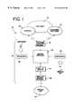
- FIG. 1is a simplified functional block diagram of the control and monitoring system of the present invention showing the communication links between the host computer, the customer, and the control and monitoring units;
- FIG. 2is a simplified logic diagram of the operation of the host computer of the control and monitoring system of the present invention
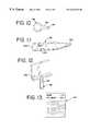
- FIG. 3is a front elevational view of a remotely located control and monitoring unit used with the control and monitoring system of the present invention
- FIG. 4is a simplified logic diagram of the operation of the remote unit of the control and monitoring system of the present invention.
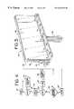
- FIG. 5is a perspective view of a dual face signboard showing the remote unit of FIG. 3 positioned to illuminate the sides of the signboard, as desired;
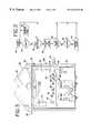
- FIG. 6is a front elevational view of the remote unit of FIG. 3 shown wired to control and monitor a single face signboard;
- FIG. 7is a front elevational view of the remote unit of FIG. 3 shown wired to control and monitor a dual face signboard;
- FIG. 8is a front elevational view of the remote unit shown with an auxiliary relay cabinet used to permit control and monitoring of electrical apparatus comprising a relatively large electrical load;
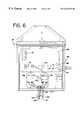
- FIG. 9is a simplified schematic diagram of the alternating current sensor module preferably used with each remote unit of the present invention.
- FIG. 10refers to a personal identification data button for use in conjunction with the control and monitoring system of the present invention
- FIG. 11refers to a service wand for use in conjunction with the control and monitoring system of the present invention
- FIG. 12refers to a load located at a remote unit site for use in conjunction with the control and monitoring system of the present invention
- FIG. 13refers to a work order for use in conjunction with the control and monitoring system of the present invention.
- FIG. 1depicts this control and monitoring system 20 and shows the data communication links between a host computer 22 , customers 24 , and each remote unit 26 of the present invention.
- Each customer 24is capable of communicating with the host computer 22 through the Internet 28 , subscriber software 30 , or through other communication media including, but not limited to, a direct dial-up phone line, facsimile, paging, e-mail, or even human-to-human contact.
- the subscriber software 30is adapted for each application (e.g., monitoring utilities, monitoring traffic flow, monitoring lighting, etc.), and the customers 24 install the software on a personal computer (PC) at their home or office.
- PCpersonal computer
- Datais preferably transmitted between each customer's computer and the host computer 22 via telephone lines and modems.
- a customer interface gateway 32permits full duplex communication between the customer and host computer 22 .
- the datais stored in a server database 34 .
- Inbound messages 36 from customersmay also be routed through a customer interface gateway product data processor 38 .
- This processor 38processes data received from a customer 24 and periodically scans the data for commands from the subscriber software 30 .
- Each remote unit 26communicates with the host computer 22 via the wireless service gateway 40 .
- This gateway 40permits communication with the local server database gateway 42 .
- Inbound messages 44 received from the remote unit 26may also be transmitted through a wireless service gateway product data processor 46 to host computer 22 .
- This processor 46processes data received from the remote unit 26 and periodically scans the data for inbound messages from the remote unit for processing.
- Auxiliary components of the host system 22then relay data to the appropriate end receivers,.and provide for a notification routine which may be, for example, conducted through e-mail, facsimile, or paging networks.
- the host computer 22is on line, runs continuously, and includes auxiliary power units for back up power supply.
- Computer 22activates and deactivates the customer applications and stores “Alert” notification signals, as necessary.
- Computer 22also sends commands to each remote unit 26 .
- Computer 22further communicates with the remote units 26 regularly, and can poll them to inquire if any “Alert” signals have been generated, or if any other performance problems are present within the system.
- Computer 22also scans and processes new commands and communicates with the remote units 26 through a wireless paging network, for example.
- the commandsare preferably sent in a protocol consisting of serially transmitted frames.
- Two different protocolmay be used for sending and receiving information, each having two layers.
- One layeris application independent and defines the type of interaction between each remote unit 26 and computer 22 at the application level.
- the second layer of protocolis application dependent and defines additional information.
- the protocolis structured so that many types of information can be sent in the same packet of data.
- Each framecontains different information such as customer identification bits, product identification bits, remote unit 26 identification bits, electrical apparatus identification bits, etc.
- the operation of computer 22begins at terminal block 48 .
- the computerdetermines, at block 50 , whether it needs to perform a particular function.
- the function to be performedcan be, for example, transmitting a command signal to a remotely located control and monitoring unit 26 (see FIG. 1 ), thereby commanding that remote unit to activate or deactivate its associated electrical apparatus. While making this determination at block 50 , computer 22 is in its so-called comparison mode.
- computer 22If computer 22 needs to perform a function, it does so at block 52 and then reenters its comparison mode. If not, computer 22 determines, at decision block 54 , whether it has received a message from an external source. If not, the computer reenters its comparison mode. If so, the computer receives the message, processes it and stores it in its memory unit at block 56 so that the data can be accessed at a future time.
- computer 22determines at decision block 58 , whether the message was sent by a customer or from a different source (such as a remote unit 26 or service personnel at a job site). If the received message was sent by a customer, no alert notification subroutine need be performed and the computer reenters its comparison mode. However, if the received message was not sent by a customer, the computer determines, at decision block 60 , whether it needs to perform an alert notification subroutine. If the computer needs to perform an alert notification subroutine, it does so at block 62 and then returns to its comparison mode. If not, the computer returns immediately to its comparison mode.
- a remote unit 26 of the type preferably used with the system of the present inventionis shown in FIG. 3 .
- the unit 26is self-contained and includes a housing 64 .
- a control or logic box 66 , two relay/sensor modules 68 , AC line sensors 70 , and a back up power supply in the form of a battery 72are all preferably included within housing 64 .
- a cover or dooris preferably included as a portion of housing 64 . This cover is secured by an assembly or latch 74 when it is closed and the latch includes a locking mechanism of a type well known in the art. As will be apparent, the cover or door assembly protects the components of remote unit 26 from the outside environment.
- the control or logic box 66contains a processor board, a power supply, and a two-way radio/modem.
- An AC sensor terminal strip 76 and AC power feed terminal strip 78are also preferably included within control box 66 .
- the top portion of housing 64contains a relay/sensor module port 80 , a battery port 82 , a port 84 for a push button, and a service switch port 86 .
- Switch 88is labeled CAL and permits calibration of the system; switch 90 is labeled SVC and permits service of the electrical apparatus associated with unit 26 .
- An antenna 92is preferably mounted on housing 64 in a manner well known in the art.
- Antenna 92permits control box 66 to transmit and receive electromagnetic signals, as desired.
- Antenna 92is electrically connected to the processor board of control box 66 by a transmission line shown in the form of coaxial cable 94 .
- Antenna 92is protected from the outside environment by a plastic shroud 96 .
- a ground bolt 98is also provided within housing 64 to enable the remote unit 26 to be properly grounded.
- LED 100comprises a transmit indicator and is normally off. When it flashes, LED 100 indicates that the remote unit 26 is receiving or transmitting data across the wireless network.
- LEDS 102 , 104indicate the status of first and second alternating current power lines, respectively, during use of the AC line sensors 70 . Each LED 102 , 104 is illuminated while AC power is present on its respective line, and it will turn off during a power failure condition.
- LED 106comprises a calibrate LED and illuminates whenever service personnel depress push-button calibration switch 88 .
- LED 108comprises a network contact LED switch and will illuminate throughout the interval of time when there is sufficient radio contact with the wireless network.
- LED 110comprises a battery test indicator and will illuminate at all times except during the time interval that the unit 26 performs a battery test. While the unit 26 performs a battery test, LED 106 will flash.
- LED 112comprises a power indicator and remains illuminated while AC power is applied to unit 26 .
- the operation of the remote unit 26begins at block 114 .
- the remote unitfirst determines, at decision block 116 , whether it needs to perform one of its many available functions. At this point, remote unit 26 is in its comparison mode. If the remote unit needs to perform a function, it does so at block 118 and then reenters its comparison mode.
- remote unit 26performs an internal status check at block 120 to determine both its own operating condition and that of its associated electrical apparatus. Thereafter, the remote unit determines, at decision block 122 , whether it has detected an alert condition based on the status check performed at block 120 .
- remote unit 26stores the alert signal data in its internal memory at block 124 and then transmits an alert notification signal to the host computer 22 at block 126 before reentering its comparison mode.
- the remote unitdetermines, at block 128 , if it has received an incoming message. If so, it collects and stores the message in its internal memory at block 130 before reentering its comparison mode. If not, it simply reenters its comparison mode.
- the remote unit 26 of the present inventioncan be used in a number of applications and may control, monitor and collect data from a number of associated electrical apparatus.
- the preferred control and monitoring systemhas been generally described above and it should be apparent that the system may be used in a wide variety of controlling and monitoring applications. Nevertheless, in the following description, the system will be described as being used to control, monitor and collect data from remotely located lights, in particular signboard lights. It will be understood that the following description is for illustrative purposes only and while it does embody the principles of the present invention, this invention is in no way limited to a single application.
- FIG. 5there is shown the control and monitoring system 20 in an embodiment adapted to control, monitor and collect data from signboard light sources.
- the remote unit 26is shown mounted to the side 132 of a signboard 134 .
- the illustrated signboard 134includes a pole 136 , a first or front face 138 , and a second or back face 140 . Faces 138 , 140 are each illuminated by five light sources 142 . Each light source 142 illuminates a proportional share of its respective face.
- the logic box 66 of the remote unit 26is programmed to accurately keep track of Greenwich Mean Time on its internal clock while it also automatically calculates and makes the required adjustments for daylight Savings Time and the Diurnal Cycle (dusk/dawn). This is accomplished in part because the unit knows its location, namely, its latitude and longitude coordinates, and has those locations stored in its internal memory. Because the unit 26 knows the exact time based on its location, the customer 24 can program and thereby control and monitor the electrical apparatus associated with the unit. For instance, the customer 24 can command unit 26 to activate its associated electrical apparatus at a first desired time and later deactivate it at a second desired time. The first and second desired times may be based on standard clock time (e.g. 6:54 a.m. EST—on; 8:23 p.m. EST—off, for example), the diurnal cycle, or any combination of the two.
- standard clock timee.g. 6:54 a.m. EST—on; 8:23 p.m.
- each relay/sensor module 68includes a line receptacle 148 and a load receptacle 150 to receive electrical lines and thereby establish electrical connection with an associated AC power line and the associated electrical apparatus (e.g., signboard light source 142 ), respectively.
- the line receptacle 148 of the first relayis connected with an electrical line 152 and circuit breaker (not shown) of the second AC power line.
- the load receptacle 150 of the first relayis connected by an electrical line 154 to the electrical apparatus (not shown) associated with the first relay.
- the line receptacle 158 of the second relayis connected by an electrical line 148 and a circuit breaker (not shown) for the first AC power line.
- the load receptacle 150 of the second relayis connected with an electrical line 158 and the electrical apparatus (not shown) associated with the second relay.
- the wiring diagram shown in FIG. 7will preferably be used.
- the wiring arrangement for a dual face signboardis somewhat similar to the arrangement for a single face signboard.
- a communication cable 144connects the logic box 66 to a first relay, and auxiliary cables 146 connect the first and second relays for each face.
- the differencelies in the use of a separation cable 160 which connects the first relay of the first face of the signboard to the first relay of the second face of the signboard.
- the separation cable 160permits designation of relay sets for each face of a signboard. This is particularly advantageous during system set-up and operation.
- the line receptacle 148 of the first relayis connected with an electrical line 162 and a circuit breaker (not shown) for the first AC power line.
- the load receptacle 150 of the first relayis connected with an electrical line 164 for the electrical apparatus (not shown) associated with the first relay.
- the line receptacle 148 of the second relayis connected with an electrical line 166 and a circuit breaker (not shown) for the second AC power line.
- the load receptacle 150 of the second relayis connected with an electrical line 168 for the electrical apparatus (not shown) associated with the second relay.
- the line receptacle 148 of the third relayis connected with an electrical line 170 for a circuit breaker (not shown) for the second AC power line.
- the load receptacle 150 of the third relayis connected with an electrical line 172 for the electrical apparatus (not shown) associated with the third relay.
- the line receptacle 148 of the fourth relayis connected with an electrical line 174 for a circuit breaker (not shown) for the first AC power line.
- the load receptacle 150 of the fourth relayis connected with an electrical line 176 for the electrical apparatus (not shown) associated with the fourth relay.
- FIG. 8shows an embodiment of the present invention implementing a relay expansion cabinet.
- the housing 64 of the remote unit 26preferably includes a number of conduit punch-out portions 178 which enable conduit to connect the housing with an expansion cabinet 180 .
- the expansion cabinet 180is also equipped with conduit punch-out portions 178 to permit this connection.
- the wiring scheme for the relays 68 contained in the expansion cabinet 180is identical to the connections previously described to provide a robust system.
- the system 20will automatically determine the number of signboard faces that the remote unit is to control and monitor.
- the host computer 22polls each of the relays 68 associated with a particular remote unit 26 .
- the host computer 22polls each remote unit 26 .
- the first relay of the polled remote unit 26responds to the poll by initiating an answer back routine.
- the host computer 22again polls the remote unit 26 . If additional relays 68 are present, they each respond to their respective polls by initiating answer back routines.
- Each successively polled relayresponds through the previously polled relays and indicates whether it is connected to a previously polled relay through an auxiliary cable 146 , to another relay through a separation cable 160 , directly to the logic box 66 through a communication cable 144 , or any combination of the foregoing.
- Each successively polled relay 68will initiate an answer back routine in this fashion.
- the host computer 22stores data regarding the number of relays, the number of faces, and number of electrical apparatus controlled and monitored by the remote unit 26 at its site.
- the system 20is ready to perform its calibration routine.
- the calibrate push-button switch 88 included within logic box 66will activate the electrical apparatus associated with remote unit 26 for a predetermined period of time (approximately twenty minutes for the signboard application) so that the current drain of the connected apparatus (i.e., load) reaches its steady state operating condition. The steady state current drain is then measured and stored for later use during the monitoring of the electrical apparatus.
- the remote units 26During monitoring of the operating conditions of its associated electrical apparatus, the remote units 26 periodically measure the current delivered to the apparatus. If the measured current differs from the stored steady state current drain for the apparatus by more than a threshold value, the remote unit 26 detects a failure condition. Alternatively, the host computer may periodically poll each remote unit 26 to command that unit to check for the occurrence of a failure condition of the electrical apparatus associated with the polled unit.
- the level of current delivered to the electrical apparatusis continually monitored and measured throughout a predetermined period of time referred to as a validation period.
- the level of currentmay be measured by the remote unit 26 independently or by polling signals received from the host computer 22 commanding the unit 26 to conduct a measurement of that current level. If a failure is detected during each current measurement taken throughout the validation period, an alarm signal is transmitted to the host computer 22 , indicating that there has been at least a partial failure of the electrical apparatus. Measurement of the current then continues until the current level rises so that it is once again within the threshold range of the steady state value of the current drain. At that time, an alarm restore signal is transmitted to the host computer 22 , indicating remedy of the partial failure condition.
- the above-described alarm signalis not sent to the host computer 22 and periodic measurement resumes until the remote unit 26 detects a subsequent failure condition.
- the present inventionis also capable of distinguishing failure conditions indicating low current or partial failure from those indicating no current or total failure.
- a complete power failurewill also trigger detection of a failure condition.
- a power failuremay occur for any number of reasons, and because of this, each remote unit 26 is equipped with a back up power supply shown as battery 72 .
- the present inventionprovides for, a determination of whether the failure was due to power line failure or merely a tripped circuit breaker. If the outage is due to a tripped circuit breaker, service personnel can be dispatched to the outage site immediately so that the involuntary deactivation time of the electrical apparatus is kept to a minimum. By having the ability to determine the cause of a total failure condition, the condition may be remedied in a timely manner.
- the remote units 26detect power failures by implementing an AC sensor module 70 .
- the AC sensor module 70is shown in schematic form.
- the AC sensor module 70mounts between the meter 182 and a circuit breaker 184 .
- the logic box 66sends current to the module 70 and measures the electrical field surrounding it. To obviate any fluctuation in the AC magnetic field, the preferred embodiment of the present invention measures this field six times over a set period of time. If the module 70 detects an electrical field during any of those measurements, then the failure condition was caused by a trip condition of the attached circuit breaker and service personnel may be sent to the site to remedy the failure. Otherwise, the failure condition was caused by a loss of power in the utility line and may involve more complicated problems.
- the logic unit 66when the back up power supply battery 72 loses its charge, a signal is sent to the host computer 22 indicating this failure.
- the logic unit 66will typically have only enough power to keep its internal clock running, to maintain the data in its memory and to perform a few of its basic operating functions.
- the battery 72continues to supply power for the unit, the unit does not respond to pages or communicate with the host computer. Nevertheless, based on the notification signal, service personnel may be dispatched to remedy the problem.
- a worker or servicemanis sent to the site. Once there, he can press the service button 90 , causing all relays within the unit to close and activate the electrical apparatus for one hour. The serviceman can then determine which apparatus has failed and remedy the problem by opening the circuit breaker, replacing the apparatus, and then closing the breaker.
- customersare able to know whether service personnel have performed work they have contracted to perform at the site in a timely manner. Quality control of service performance is often a concern of customers, particularly those in the signboard advertising industry.
- the present inventioncontemplates a fail-proof quality control feature. To ensure work is done as contracted for, or service has been completed, the present invention will relay such information back to the host computer 22 in real time. This is accomplished through the use of bar codes as well as data stored on a personal ID touch button and data readers. Typically, a signboard service provider will carry with him a personal ID data button as well as a wand that operates both as a bar code and a button data reader.
- the service providertransmits the encoded information on his personal button to the wand by touching the button to the wand. This encoded information is then temporarily stored in the wand.
- the service providerthen touches the wand to a data button located at the work site. Upon doing so, information regarding the location of the work site is transmitted to the memory unit contained within the wand. That location information is encoded in each of the data buttons located at each of the work sites.
- the service providerAfter completing the job, the service provider then scans the bar code located on the sign with the wand to store the signboard information. Any additional information may also be read by the wand.
- the service providertouches the wand to the touch button 196 located on the remote unit 26 .
- the logic box 66may then download this information to host computer 22 so that customers may be assured the work was performed according to the contract. All of this information is then sent to the host computer 22 .
- This particular featuremay be best understood by the use of an example in conjunction with FIGS. 10-13.
- Service personnelcarry with them a personal identification data button like that shown in FIG. 10 which holds all of their work related data.
- This informationmay include their name, ID number, and any other such information.
- this data button 186may be integral with a tab 188 and loop 190 so as to easily attach to a keychain, for example.
- Each sitewill have at least two data buttons, one on the housing 64 of the remote unit 26 (data button 196 ), and one at the site of the load (data button 198 on the pole 136 as in FIG. 12, for example).
- Examples for which wand 192 may be used in the signboard applicationinclude changing the sign on a particular signboard, cutting the grass around the pole of the signboard, and painting the pole.
- a servicemanwill arrive at the site and touch his personal ID data button 186 to an end 200 of the service wand 192 . This transfers his personal data into the wand, and may be displayed in the text window 202 of the wand.
- the servicemanthen touches the end 200 to data button 198 associated with the pole so as to transfer location data to the wand 192 .
- the tip 204 of the wand 192reads the bar code 206 on the sign and transfers this data to the wand 192 .
- the servicemanthen paints the pole and cuts the brush, and touches the tip 204 to the appropriate bar code placed on the work order 194 shown in FIG. 13 .
- This transfer of dataneed not be performed in this order, but may be performed in any order as long as all of the data eventually is read into wand 192 .
- the servicemantouches the end 200 of wand 192 to the data button 196 of the remote unit 26 , and all of the data is transferred to the unit.
- This datamay then be transferred to the host computer 22 so that a customer is able to know when, where and by whom a work order was performed.
Landscapes
- Engineering & Computer Science (AREA)
- Computer Networks & Wireless Communication (AREA)
- Physics & Mathematics (AREA)
- General Physics & Mathematics (AREA)
- Selective Calling Equipment (AREA)
Abstract
Description
The present invention relates generally to a system for controlling and monitoring electrical apparatus and, more particularly, to a system which utilizes two-way wireless communications to control, monitor and collect data from electrical apparatus.
The present manual methods used for controlling and monitoring electrical apparatus are expensive and time consuming. For example, a person or business having remotely located electrical apparatus typically needs to manually check on such apparatus to determine whether the apparatus is operating properly. This gets particularly expensive when the electrical apparatus is located at geographically diverse positions. Frequently, in such situations, employees are hired to travel between each apparatus site to examine each apparatus and report on the status of the apparatus.
A control and monitoring system capable of not only controlling such diversely located apparatus, but also of monitoring and collecting data from the apparatus, would obviate the need for such field inspections. Also, such a control and monitoring system has the potential of optimizing the efficiency of the network of apparatus and significantly reducing energy consumption. There are many applications which would benefit from the use of such a control and monitoring system, and although the present invention is described in the context of several particular applications, the invention should not be construed as being limited to these applications.
One application for which the present invention could be advantageously used is the monitoring of utility systems. The conventional method of monitoring and collecting electrical energy consumption is to manually read a meter located at a site by sending personnel to that site. The present invention provides for a remote reading of the monthly electrical consumption at a particular site, thereby eliminating the need to manually read the meter at each site. The invention is also capable of discontinuing service to a utility customer when so commanded by the utility company.
Another application for the present invention is monitoring traffic through a so-called automobile drive-through line of a fast food type restaurant. In particular, certain data such as the time spent by each customer waiting for his/her order, could obtained at a central monitoring facility.
Another potential application for the present invention is the monitoring of the quality of gasoline at fuel stations. Again, the conventional method has been to send personnel to each station to test each gasoline holding tank. The present invention provides for quality, and quantity testing of a holding tank from a remote location. Again, cost and time are saved.
Another use of the present invention is the monitoring of the remaining capacity of a remotely located trash compactor. From such a reading, the invention is capable of activating and deactivating the compactor, as desired.
Other applications for the present invention include lighting systems, climate control systems, irrigation systems, and traffic control systems. The lighting applications include the control and monitoring of household and business lights, airport runway lights, and signboards, such as those typically utilized for advertising goods and services. These include triface signboards, mechanical signboards, and multiple face signboards, among others.
Accordingly, it is a general object of the present invention to provide a control and monitoring system which establishes two-way wireless communication between a host computer and a control and monitoring unit located at a site remote from the host computer.
It is a more specific object of the present invention to provide a system which establishes two-way wireless communications for controlling and monitoring an electrical apparatus remotely located from a host computer.
It is still another object of the present invention is to provide remote control and monitoring units which are stand-alone units and are independently capable of controlling and monitoring electrical apparatus.
Still another object of the present invention is to provide a system which establishes two-way wireless communications and permits collection of data regarding the operating conditions of electrical apparatus.
These and other objects, features and advantages of the present invention will be clearly understood through a consideration of the following detailed description.
According to the present invention, there is provided a system for controlling, monitoring, and collecting data from electrical apparatus. The system comprises a host computer having a memory for storing data regarding the operating conditions of the electrical apparatus, a processor for processing such data and input/output ports which allow the host computer to communicate with peripherals and a plurality of controlling and monitoring units remotely located from the host computer. The system further includes the control and monitoring units, each unit being associated with electrical apparatus for controlling, monitoring and collecting data from the same. The control and monitoring units communicate with the host computer over a wireless network while performing those functions.
The features of the present invention which are believed to be novel are set forth with particularity in the appended claims. The invention, together with the further objects and advantages thereof, may best be understood by reference to the following description taken in conjunction with the accompanying drawings, in the several figures of which like reference numerals identify like elements, and in which:
FIG. 1 is a simplified functional block diagram of the control and monitoring system of the present invention showing the communication links between the host computer, the customer, and the control and monitoring units;
FIG. 2 is a simplified logic diagram of the operation of the host computer of the control and monitoring system of the present invention;
FIG. 3 is a front elevational view of a remotely located control and monitoring unit used with the control and monitoring system of the present invention;
FIG. 4 is a simplified logic diagram of the operation of the remote unit of the control and monitoring system of the present invention;
FIG. 5 is a perspective view of a dual face signboard showing the remote unit of FIG. 3 positioned to illuminate the sides of the signboard, as desired;
FIG. 6 is a front elevational view of the remote unit of FIG. 3 shown wired to control and monitor a single face signboard;
FIG. 7 is a front elevational view of the remote unit of FIG. 3 shown wired to control and monitor a dual face signboard;
FIG. 8 is a front elevational view of the remote unit shown with an auxiliary relay cabinet used to permit control and monitoring of electrical apparatus comprising a relatively large electrical load;
FIG. 9 is a simplified schematic diagram of the alternating current sensor module preferably used with each remote unit of the present invention;
FIG. 10 refers to a personal identification data button for use in conjunction with the control and monitoring system of the present invention;
FIG. 11 refers to a service wand for use in conjunction with the control and monitoring system of the present invention;
FIG. 12 refers to a load located at a remote unit site for use in conjunction with the control and monitoring system of the present invention;
FIG. 13 refers to a work order for use in conjunction with the control and monitoring system of the present invention.
Referring to the Figures, and particularly to FIG. 1, there is shown a control and monitoring system generally designated byreference numeral 20 which utilizes two-way wireless communications in accordance with the principles of the present invention. FIG. 1 depicts this control andmonitoring system 20 and shows the data communication links between ahost computer 22,customers 24, and eachremote unit 26 of the present invention. Eachcustomer 24 is capable of communicating with thehost computer 22 through the Internet28,subscriber software 30, or through other communication media including, but not limited to, a direct dial-up phone line, facsimile, paging, e-mail, or even human-to-human contact. Thesubscriber software 30 is adapted for each application (e.g., monitoring utilities, monitoring traffic flow, monitoring lighting, etc.), and thecustomers 24 install the software on a personal computer (PC) at their home or office. This gives the customers desktop control of their applications and allows the customers to create a database on their computers for each remote unit within their particular application. Data is preferably transmitted between each customer's computer and thehost computer 22 via telephone lines and modems.
Acustomer interface gateway 32 permits full duplex communication between the customer andhost computer 22. When data is sent from the customer to the host computer, the data is stored in aserver database 34.Inbound messages 36 from customers may also be routed through a customer interface gatewayproduct data processor 38. Thisprocessor 38 processes data received from acustomer 24 and periodically scans the data for commands from thesubscriber software 30.
Eachremote unit 26 communicates with thehost computer 22 via thewireless service gateway 40. Thisgateway 40 permits communication with the localserver database gateway 42.Inbound messages 44 received from theremote unit 26 may also be transmitted through a wireless service gatewayproduct data processor 46 to hostcomputer 22. Thisprocessor 46 processes data received from theremote unit 26 and periodically scans the data for inbound messages from the remote unit for processing. Auxiliary components of thehost system 22 then relay data to the appropriate end receivers,.and provide for a notification routine which may be, for example, conducted through e-mail, facsimile, or paging networks.
Thehost computer 22 is on line, runs continuously, and includes auxiliary power units for back up power supply.Computer 22 activates and deactivates the customer applications and stores “Alert” notification signals, as necessary.Computer 22 also sends commands to eachremote unit 26.Computer 22 further communicates with theremote units 26 regularly, and can poll them to inquire if any “Alert” signals have been generated, or if any other performance problems are present within the system.Computer 22 also scans and processes new commands and communicates with theremote units 26 through a wireless paging network, for example.
When a paging network is used for these purposes, the commands are preferably sent in a protocol consisting of serially transmitted frames. Two different protocol may be used for sending and receiving information, each having two layers. One layer is application independent and defines the type of interaction between eachremote unit 26 andcomputer 22 at the application level. The second layer of protocol is application dependent and defines additional information. The protocol is structured so that many types of information can be sent in the same packet of data. Each frame contains different information such as customer identification bits, product identification bits,remote unit 26 identification bits, electrical apparatus identification bits, etc.
Referring now to FIG. 2, the operation ofcomputer 22 is shown in logic diagram form. The operation of the computer begins atterminal block 48. The computer then determines, atblock 50, whether it needs to perform a particular function. The function to be performed can be, for example, transmitting a command signal to a remotely located control and monitoring unit26 (see FIG.1), thereby commanding that remote unit to activate or deactivate its associated electrical apparatus. While making this determination atblock 50,computer 22 is in its so-called comparison mode.
Ifcomputer 22 needs to perform a function, it does so atblock 52 and then reenters its comparison mode. If not,computer 22 determines, atdecision block 54, whether it has received a message from an external source. If not, the computer reenters its comparison mode. If so, the computer receives the message, processes it and stores it in its memory unit atblock 56 so that the data can be accessed at a future time.
Thereafter,computer 22 determines atdecision block 58, whether the message was sent by a customer or from a different source (such as aremote unit 26 or service personnel at a job site). If the received message was sent by a customer, no alert notification subroutine need be performed and the computer reenters its comparison mode. However, if the received message was not sent by a customer, the computer determines, atdecision block 60, whether it needs to perform an alert notification subroutine. If the computer needs to perform an alert notification subroutine, it does so atblock 62 and then returns to its comparison mode. If not, the computer returns immediately to its comparison mode.
Aremote unit 26 of the type preferably used with the system of the present invention is shown in FIG.3. As shown, theunit 26 is self-contained and includes ahousing 64. A control orlogic box 66, two relay/sensor modules 68,AC line sensors 70, and a back up power supply in the form of abattery 72 are all preferably included withinhousing 64. Although not shown in FIG. 3, a cover or door is preferably included as a portion ofhousing 64. This cover is secured by an assembly or latch74 when it is closed and the latch includes a locking mechanism of a type well known in the art. As will be apparent, the cover or door assembly protects the components ofremote unit 26 from the outside environment.
The control orlogic box 66 contains a processor board, a power supply, and a two-way radio/modem. An ACsensor terminal strip 76 and AC powerfeed terminal strip 78 are also preferably included withincontrol box 66. As shown, the top portion ofhousing 64 contains a relay/sensor module port 80, abattery port 82, aport 84 for a push button, and aservice switch port 86. There are also two push button switches88,90.Switch 88 is labeled CAL and permits calibration of the system;switch 90 is labeled SVC and permits service of the electrical apparatus associated withunit 26.
Anantenna 92 is preferably mounted onhousing 64 in a manner well known in the art.Antenna 92 permits controlbox 66 to transmit and receive electromagnetic signals, as desired.Antenna 92 is electrically connected to the processor board ofcontrol box 66 by a transmission line shown in the form ofcoaxial cable 94.Antenna 92 is protected from the outside environment by aplastic shroud 96. Aground bolt 98 is also provided withinhousing 64 to enable theremote unit 26 to be properly grounded.
Included as part of the circuitry withinlogic box 66 are seven verification light-emitting diodes (LEDS)100-112.LED 100 comprises a transmit indicator and is normally off. When it flashes,LED 100 indicates that theremote unit 26 is receiving or transmitting data across the wireless network.LEDS AC line sensors 70. EachLED LED 106 comprises a calibrate LED and illuminates whenever service personnel depress push-button calibration switch 88.LED 108 comprises a network contact LED switch and will illuminate throughout the interval of time when there is sufficient radio contact with the wireless network. LED110 comprises a battery test indicator and will illuminate at all times except during the time interval that theunit 26 performs a battery test. While theunit 26 performs a battery test,LED 106 will flash. LED112 comprises a power indicator and remains illuminated while AC power is applied tounit 26.
Referring now to FIG. 4, there is shown the operation of a control andmonitoring unit 26 in logic diagram form. The operation of theremote unit 26 begins atblock 114. The remote unit first determines, atdecision block 116, whether it needs to perform one of its many available functions. At this point,remote unit 26 is in its comparison mode. If the remote unit needs to perform a function, it does so atblock 118 and then reenters its comparison mode.
It not,remote unit 26 performs an internal status check atblock 120 to determine both its own operating condition and that of its associated electrical apparatus. Thereafter, the remote unit determines, atdecision block 122, whether it has detected an alert condition based on the status check performed atblock 120.
If so,remote unit 26 stores the alert signal data in its internal memory atblock 124 and then transmits an alert notification signal to thehost computer 22 atblock 126 before reentering its comparison mode.
If no alert condition is detected, the remote unit determines, atblock 128, if it has received an incoming message. If so, it collects and stores the message in its internal memory atblock 130 before reentering its comparison mode. If not, it simply reenters its comparison mode.
As previously discussed, theremote unit 26 of the present invention can be used in a number of applications and may control, monitor and collect data from a number of associated electrical apparatus. The preferred control and monitoring system has been generally described above and it should be apparent that the system may be used in a wide variety of controlling and monitoring applications. Nevertheless, in the following description, the system will be described as being used to control, monitor and collect data from remotely located lights, in particular signboard lights. It will be understood that the following description is for illustrative purposes only and while it does embody the principles of the present invention, this invention is in no way limited to a single application.
Referring now to FIG. 5, there is shown the control andmonitoring system 20 in an embodiment adapted to control, monitor and collect data from signboard light sources. Theremote unit 26 is shown mounted to theside 132 of asignboard 134. The illustratedsignboard 134 includes apole 136, a first orfront face 138, and a second or backface 140.Faces light sources 142. Eachlight source 142 illuminates a proportional share of its respective face.
Thelogic box 66 of theremote unit 26 is programmed to accurately keep track of Greenwich Mean Time on its internal clock while it also automatically calculates and makes the required adjustments for daylight Savings Time and the Diurnal Cycle (dusk/dawn). This is accomplished in part because the unit knows its location, namely, its latitude and longitude coordinates, and has those locations stored in its internal memory. Because theunit 26 knows the exact time based on its location, thecustomer 24 can program and thereby control and monitor the electrical apparatus associated with the unit. For instance, thecustomer 24 can commandunit 26 to activate its associated electrical apparatus at a first desired time and later deactivate it at a second desired time. The first and second desired times may be based on standard clock time (e.g. 6:54 a.m. EST—on; 8:23 p.m. EST—off, for example), the diurnal cycle, or any combination of the two.
Referring now to FIG. 6, theremote unit 26 is shown as being wired to control and monitor a single face signboard. In this case, two relay/sensor modules 68 are used. Acommunication cable 144 connects thelogic box 66 to the first relay/sensor module and anauxiliary cable 146 connects the first relay/sensor module to the second relay/sensor module, as shown. As shown, each relay/sensor module 68 includes aline receptacle 148 and aload receptacle 150 to receive electrical lines and thereby establish electrical connection with an associated AC power line and the associated electrical apparatus (e.g., signboard light source142), respectively. For a single face signboard set-up, theline receptacle 148 of the first relay is connected with anelectrical line 152 and circuit breaker (not shown) of the second AC power line. Theload receptacle 150 of the first relay is connected by anelectrical line 154 to the electrical apparatus (not shown) associated with the first relay. Similarly, theline receptacle 158 of the second relay is connected by anelectrical line 148 and a circuit breaker (not shown) for the first AC power line. Theload receptacle 150 of the second relay is connected with anelectrical line 158 and the electrical apparatus (not shown) associated with the second relay.
If theremote unit 26 is used to control a dual face signboard, the wiring diagram shown in FIG. 7 will preferably be used. As shown, the wiring arrangement for a dual face signboard is somewhat similar to the arrangement for a single face signboard. Acommunication cable 144 connects thelogic box 66 to a first relay, andauxiliary cables 146 connect the first and second relays for each face. The difference lies in the use of a separation cable160 which connects the first relay of the first face of the signboard to the first relay of the second face of the signboard. As is described in further detail, the separation cable160 permits designation of relay sets for each face of a signboard. This is particularly advantageous during system set-up and operation.
In the dual face signboard arrangement, theline receptacle 148 of the first relay is connected with anelectrical line 162 and a circuit breaker (not shown) for the first AC power line. Theload receptacle 150 of the first relay is connected with anelectrical line 164 for the electrical apparatus (not shown) associated with the first relay. Theline receptacle 148 of the second relay is connected with anelectrical line 166 and a circuit breaker (not shown) for the second AC power line. Theload receptacle 150 of the second relay is connected with anelectrical line 168 for the electrical apparatus (not shown) associated with the second relay. Theline receptacle 148 of the third relay is connected with anelectrical line 170 for a circuit breaker (not shown) for the second AC power line. Theload receptacle 150 of the third relay is connected with anelectrical line 172 for the electrical apparatus (not shown) associated with the third relay. Theline receptacle 148 of the fourth relay is connected with anelectrical line 174 for a circuit breaker (not shown) for the first AC power line. Theload receptacle 150 of the fourth relay is connected with anelectrical line 176 for the electrical apparatus (not shown) associated with the fourth relay.
More than fourrelays 68 may be required for some applications. In signboard applications, each face of the signboard typically requires two relays, depending on the electrical load of the light sources, so in multi-face signboard applications with signboards having three or more faces, an expansion cabinet may be needed to house additional relays. FIG. 8 shows an embodiment of the present invention implementing a relay expansion cabinet. Thehousing 64 of theremote unit 26 preferably includes a number of conduit punch-outportions 178 which enable conduit to connect the housing with anexpansion cabinet 180. Theexpansion cabinet 180 is also equipped with conduit punch-outportions 178 to permit this connection. The wiring scheme for therelays 68 contained in theexpansion cabinet 180 is identical to the connections previously described to provide a robust system.
Additional novel features of the present invention will now be discussed as they pertain to the use of the system in a signboard application. Again, it will be understood that such features are not intended to be limited to only a signboard application, but they may be used in other applications as well.
During set-up of theremote unit 26 at an established signboard site, thesystem 20 will automatically determine the number of signboard faces that the remote unit is to control and monitor. To achieve this feature, thehost computer 22 polls each of therelays 68 associated with a particularremote unit 26. During the preferred polling scheme, thehost computer 22 polls eachremote unit 26. The first relay of the polledremote unit 26 responds to the poll by initiating an answer back routine. Upon receipt of an answer signal, thehost computer 22 again polls theremote unit 26. If additional relays68 are present, they each respond to their respective polls by initiating answer back routines. Each successively polled relay responds through the previously polled relays and indicates whether it is connected to a previously polled relay through anauxiliary cable 146, to another relay through a separation cable160, directly to thelogic box 66 through acommunication cable 144, or any combination of the foregoing. Each successively polledrelay 68 will initiate an answer back routine in this fashion. When thelast relay 68 answers back, thehost computer 22 stores data regarding the number of relays, the number of faces, and number of electrical apparatus controlled and monitored by theremote unit 26 at its site.
After this set-up routine is completed, thesystem 20 is ready to perform its calibration routine. The calibrate push-button switch 88 included withinlogic box 66 will activate the electrical apparatus associated withremote unit 26 for a predetermined period of time (approximately twenty minutes for the signboard application) so that the current drain of the connected apparatus (i.e., load) reaches its steady state operating condition. The steady state current drain is then measured and stored for later use during the monitoring of the electrical apparatus.
During monitoring of the operating conditions of its associated electrical apparatus, theremote units 26 periodically measure the current delivered to the apparatus. If the measured current differs from the stored steady state current drain for the apparatus by more than a threshold value, theremote unit 26 detects a failure condition. Alternatively, the host computer may periodically poll eachremote unit 26 to command that unit to check for the occurrence of a failure condition of the electrical apparatus associated with the polled unit.
If a failure condition is detected, the level of current delivered to the electrical apparatus is continually monitored and measured throughout a predetermined period of time referred to as a validation period. The level of current may be measured by theremote unit 26 independently or by polling signals received from thehost computer 22 commanding theunit 26 to conduct a measurement of that current level. If a failure is detected during each current measurement taken throughout the validation period, an alarm signal is transmitted to thehost computer 22, indicating that there has been at least a partial failure of the electrical apparatus. Measurement of the current then continues until the current level rises so that it is once again within the threshold range of the steady state value of the current drain. At that time, an alarm restore signal is transmitted to thehost computer 22, indicating remedy of the partial failure condition.
If any of the measurements during the validation period indicate that a failure condition is not present, the above-described alarm signal is not sent to thehost computer 22 and periodic measurement resumes until theremote unit 26 detects a subsequent failure condition.
The present invention is also capable of distinguishing failure conditions indicating low current or partial failure from those indicating no current or total failure. A complete power failure will also trigger detection of a failure condition. A power failure may occur for any number of reasons, and because of this, eachremote unit 26 is equipped with a back up power supply shown asbattery 72. In the case of such a failure, it would be advantageous to know, and the present invention provides for, a determination of whether the failure was due to power line failure or merely a tripped circuit breaker. If the outage is due to a tripped circuit breaker, service personnel can be dispatched to the outage site immediately so that the involuntary deactivation time of the electrical apparatus is kept to a minimum. By having the ability to determine the cause of a total failure condition, the condition may be remedied in a timely manner.
As shown in the Figures, theremote units 26 detect power failures by implementing anAC sensor module 70. Referring now to FIG. 9, theAC sensor module 70 is shown in schematic form. TheAC sensor module 70 mounts between themeter 182 and a circuit breaker184. Thelogic box 66 sends current to themodule 70 and measures the electrical field surrounding it. To obviate any fluctuation in the AC magnetic field, the preferred embodiment of the present invention measures this field six times over a set period of time. If themodule 70 detects an electrical field during any of those measurements, then the failure condition was caused by a trip condition of the attached circuit breaker and service personnel may be sent to the site to remedy the failure. Otherwise, the failure condition was caused by a loss of power in the utility line and may involve more complicated problems.
In another feature of the present invention, when the back uppower supply battery 72 loses its charge, a signal is sent to thehost computer 22 indicating this failure. In this state, thelogic unit 66 will typically have only enough power to keep its internal clock running, to maintain the data in its memory and to perform a few of its basic operating functions. Although thebattery 72 continues to supply power for the unit, the unit does not respond to pages or communicate with the host computer. Nevertheless, based on the notification signal, service personnel may be dispatched to remedy the problem.
In another feature of the present invention, after a failure of an operating condition has been determined and located by the unit, such as an inoperative bulb in the case of use of the system in a signboard application, a worker or serviceman is sent to the site. Once there, he can press theservice button 90, causing all relays within the unit to close and activate the electrical apparatus for one hour. The serviceman can then determine which apparatus has failed and remedy the problem by opening the circuit breaker, replacing the apparatus, and then closing the breaker.
As another useful feature of the present invention, customers are able to know whether service personnel have performed work they have contracted to perform at the site in a timely manner. Quality control of service performance is often a concern of customers, particularly those in the signboard advertising industry. The present invention contemplates a fail-proof quality control feature. To ensure work is done as contracted for, or service has been completed, the present invention will relay such information back to thehost computer 22 in real time. This is accomplished through the use of bar codes as well as data stored on a personal ID touch button and data readers. Typically, a signboard service provider will carry with him a personal ID data button as well as a wand that operates both as a bar code and a button data reader. When the service has been performed in accordance with the contract, the service provider transmits the encoded information on his personal button to the wand by touching the button to the wand. This encoded information is then temporarily stored in the wand. The service provider then touches the wand to a data button located at the work site. Upon doing so, information regarding the location of the work site is transmitted to the memory unit contained within the wand. That location information is encoded in each of the data buttons located at each of the work sites. After completing the job, the service provider then scans the bar code located on the sign with the wand to store the signboard information. Any additional information may also be read by the wand. Finally, the service provider touches the wand to thetouch button 196 located on theremote unit 26. Thelogic box 66 may then download this information tohost computer 22 so that customers may be assured the work was performed according to the contract. All of this information is then sent to thehost computer 22.
This particular feature may be best understood by the use of an example in conjunction with FIGS. 10-13. Service personnel carry with them a personal identification data button like that shown in FIG. 10 which holds all of their work related data. This information may include their name, ID number, and any other such information. Typically, thisdata button 186 may be integral with atab 188 andloop 190 so as to easily attach to a keychain, for example.
When service needs to be performed at an electrical apparatus site, the service personnel are directed to such location and will bring theservice wand 192 depicted in FIG. 11 as well as any other needed supplies such as thework order 194 shown in FIG.13. Each site will have at least two data buttons, one on thehousing 64 of the remote unit26 (data button196), and one at the site of the load (data button 198 on thepole 136 as in FIG. 12, for example).
Examples for whichwand 192 may be used in the signboard application include changing the sign on a particular signboard, cutting the grass around the pole of the signboard, and painting the pole. A serviceman will arrive at the site and touch his personalID data button 186 to anend 200 of theservice wand 192. This transfers his personal data into the wand, and may be displayed in thetext window 202 of the wand. The serviceman then touches theend 200 todata button 198 associated with the pole so as to transfer location data to thewand 192. After the sign is changed, thetip 204 of thewand 192 reads thebar code 206 on the sign and transfers this data to thewand 192. The serviceman then paints the pole and cuts the brush, and touches thetip 204 to the appropriate bar code placed on thework order 194 shown in FIG.13. This transfer of data need not be performed in this order, but may be performed in any order as long as all of the data eventually is read intowand 192. Thereafter, the serviceman touches theend 200 ofwand 192 to thedata button 196 of theremote unit 26, and all of the data is transferred to the unit. This data may then be transferred to thehost computer 22 so that a customer is able to know when, where and by whom a work order was performed.
While particular embodiments of the invention have been shown and described, it will be obvious to those skilled in the art that changes and modifications may be made therein without departing from the invention in its broader aspects, and, therefore, the aim in the appended claims is to cover all such changes and modifications as fall within the true spirit and scope of the invention.
Claims (16)
1. A system for controlling, monitoring, and collecting data from devices, comprising;
a host computer including an internal memory for storing a plurality of protocols for a plurality of applications, said computer having means for selecting one of said protocols corresponding to one of said applications and further including means for sending a text message to remote units associated with each of said devices as determined by said selected protocol, said host computer further including means for receiving a text message;
a customer interface capable of full-duplex communication with said host computer thereby having the ability to provide control of their applications and further having the ability to receive signals indicative of operational parameters of said devices;
a remote unit associated with each of said devices for controlling, monitoring, and collecting data including said selected protocol, said unit further having means for sending a text message to said host computer, said unit further including means for receiving a text message from said computer.
2. A system for the controlling, monitoring, and collecting data from electrical devices as defined in claim1 wherein said means for sending a text message includes a protocol comprising a first and a second layer, said first layer being application independent and said second layer being application dependent.
3. A system for the controlling, monitoring, and collecting data from electrical devices as defined in claim1 wherein said means for receiving a text message comprise a protocol having a first and a second layer, said first layer being application independent and said layer being application dependent.
4. A system for controlling, monitoring, and collecting data from electrical devices as defined in claim3 wherein said unit includes a relay.
5. A system for controlling, monitoring, and collecting data from electrical devices as defined in claim3 wherein said unit includes and AC current sensor.
6. A system for controlling, monitoring, and collecting data from electrical devices as defined in claim3 wherein said unit included a stand-by battery.
7. A system for controlling, monitoring, and collecting data from electrical devices as defined in claim1 wherein said unit includes a logic circuit which automatically calculates for changes in the diurnal cycle.
8. A system for controlling, monitoring, and collecting data from electrical devices as defined in claim1 wherein said unit includes an antenna and a cover integral with said housing adapted to shield said antenna.
9. A system for controlling, monitoring, and collecting data from electrical devices as defined in claim1 wherein said host computer polls said logic circuit current, said logic circuit current responds to said host computer and said host computer determines the status of said load for said device.
10. A system for the controlling, monitoring, and collecting data from electrical devices as defined in claim1 wherein said logic circuit includes a calibration button for determining a maximum stable load current value.
11. A system for the controlling, monitoring, and collecting data from electrical devices as defined in claim5 wherein said AC current sensor samples an electrical field between a meter and a circuit breaker associated with said device.
12. A system for the controlling, monitoring, and collecting data from electrical devices as defined in claim1 wherein said logic circuit includes a service button for providing current to as associated load for a predetermined period of time.
13. A system for controlling, monitoring, and collecting data from electrical devices as defined in claim1 wherein said housing includes a data port.
14. A system for controlling, monitoring, and collecting data from electrical devices as defined in claim13 further including a data wand, said wand being capable of reading a bar code and a data port, said wand further being capable of transferring data to said data port on said housing.
15. A system for controlling, monitoring, and collecting data from devices, comprising;
a host computer including an internal memory for storing a plurality of protocols for a plurality of applications, said computer having means for selecting one of said protocols corresponding to one of said applications and further including means for sending a text message to remote units associated with each of said devices as determined by said selected protocol, said sending means includes a protocol comprising a first and second layer, said first layer being application independent and said second layer being application dependent, said host computer further including means for receiving a text message, said receiving means includes a protocol having a first and a second layer, said first layer being application independent and said second layer being application dependent;
a customer interface capable of full-duplex communication with said host computer thereby having the ability to provide control of their applications and further having the ability to receive signals indicative of operational parameters of said devices;
a remote unit associated with each of said devices for controlling, monitoring, and collecting data including said selected protocol, said unit further having said means for sending a text message to said host computer, said unit further including means for receiving a text message from said computer.
16. A system for the controlling, monitoring, and collecting data from electrical devices, wherein said unit includes a relay, on AC current sensor, and a stand-by battery.
Priority Applications (1)
| Application Number | Priority Date | Filing Date | Title |
|---|---|---|---|
| US08/955,808US6236332B1 (en) | 1997-10-22 | 1997-10-22 | Control and monitoring system |
Applications Claiming Priority (1)
| Application Number | Priority Date | Filing Date | Title |
|---|---|---|---|
| US08/955,808US6236332B1 (en) | 1997-10-22 | 1997-10-22 | Control and monitoring system |
Publications (1)
| Publication Number | Publication Date |
|---|---|
| US6236332B1true US6236332B1 (en) | 2001-05-22 |
Family
ID=25497373
Family Applications (1)
| Application Number | Title | Priority Date | Filing Date |
|---|---|---|---|
| US08/955,808Expired - LifetimeUS6236332B1 (en) | 1997-10-22 | 1997-10-22 | Control and monitoring system |
Country Status (1)
| Country | Link |
|---|---|
| US (1) | US6236332B1 (en) |
Cited By (218)
| Publication number | Priority date | Publication date | Assignee | Title |
|---|---|---|---|---|
| US20020035497A1 (en)* | 2000-06-09 | 2002-03-21 | Jeff Mazereeuw | System and method for utility enterprise management |
| US20020059412A1 (en)* | 2000-10-04 | 2002-05-16 | Jean-Patrick Azpitarte | System for remotely managing maintenance of a set of facilities |
| US20020062221A1 (en)* | 2000-11-21 | 2002-05-23 | Seibert Roy E. | Distribution and notification system and method for filter replacement cartridges |
| US20020082748A1 (en)* | 2000-06-15 | 2002-06-27 | Internet Energy Systems, Inc. | Utility monitoring and control systems |
| US20020095269A1 (en)* | 2001-01-17 | 2002-07-18 | Francesco Natalini | System for monitoring and servicing appliances |
| US20020107586A1 (en)* | 2001-02-07 | 2002-08-08 | Bruce Kreikemeier | Method and means for reading the status of and controlling irrigation components |
| US20020111698A1 (en)* | 2001-02-09 | 2002-08-15 | Marco Graziano | Web-based system for monitoring and/or controlling home devices |
| US20020124081A1 (en)* | 2001-01-26 | 2002-09-05 | Netbotz Inc. | Method and system for a set of network appliances which can be connected to provide enhanced collaboration, scalability, and reliability |
| US20020125998A1 (en)* | 1998-06-22 | 2002-09-12 | Petite Thomas D. | System and method for monitoring and controlling remote devices |
| US6456045B1 (en) | 1999-04-16 | 2002-09-24 | Midtronics, Inc. | Integrated conductance and load test based electronic battery tester |
| US6466025B1 (en) | 2000-01-13 | 2002-10-15 | Midtronics, Inc. | Alternator tester |
| US6469511B1 (en) | 2001-07-18 | 2002-10-22 | Midtronics, Inc. | Battery clamp with embedded environment sensor |
| US20020161885A1 (en)* | 1999-10-27 | 2002-10-31 | Netbotz Inc. | Methods for displaying physical network topology and environmental status by location, organization, or responsible party |
| US20020174223A1 (en)* | 1999-10-27 | 2002-11-21 | Netbotz Inc. | Method and apparatus for replay of historical oath |
| US20020186691A1 (en)* | 2000-04-17 | 2002-12-12 | Steven Bristow | Software and protocol structure for an automated user notification system |
| US6495990B2 (en) | 1999-09-01 | 2002-12-17 | Keith S. Champlin | Method and apparatus for evaluating stored charge in an electrochemical cell or battery |
| US20020193955A1 (en)* | 1999-04-08 | 2002-12-19 | Bertness Kevin I. | Battery test module |
| US20030027593A1 (en)* | 2001-08-06 | 2003-02-06 | Howard Michael L. | Communications module for wireless communications with an electronic device to enable remote access |
| US6529723B1 (en)* | 1999-07-06 | 2003-03-04 | Televoke, Inc. | Automated user notification system |
| EP1289248A1 (en)* | 2001-08-10 | 2003-03-05 | Eric Denis | Wireless processing system for switching, controlling and monitoring appliances adapted for multiple users |
| US6556019B2 (en) | 1999-04-30 | 2003-04-29 | Midtronics, Inc. | Electronic battery tester |
| US20030088375A1 (en)* | 2001-10-17 | 2003-05-08 | Bertness Kevin I. | Electronic battery tester with relative test output |
| US20030092308A1 (en)* | 2001-11-14 | 2003-05-15 | Bertness Kevin I. | Kelvin connector for a battery post |
| US6586941B2 (en) | 2000-03-27 | 2003-07-01 | Midtronics, Inc. | Battery tester with databus |
| US20030124417A1 (en)* | 1999-04-08 | 2003-07-03 | Bertness Kevin I. | Battery test module |
| US20030135611A1 (en)* | 2002-01-14 | 2003-07-17 | Dean Kemp | Self-monitoring service system with improved user administration and user access control |
| US6621272B2 (en) | 2001-10-12 | 2003-09-16 | Keith S. Champlin | Programmable current exciter for measuring AC immittance of cells and batteries |
| US20030184258A1 (en)* | 2001-06-22 | 2003-10-02 | Vonderhaar J. David | Booster pack with storage capacitor |
| US20030191589A1 (en)* | 2002-04-04 | 2003-10-09 | David Fletcher | Method and devices for wireless communication between test and control devices and power distribution devices |
| US6633165B2 (en) | 1997-11-03 | 2003-10-14 | Midtronics, Inc. | In-vehicle battery monitor |
| US20030208480A1 (en)* | 2002-05-03 | 2003-11-06 | Netbotz, Inc. | Method and apparatus for collecting and displaying network device information |
| US6696819B2 (en) | 2002-01-08 | 2004-02-24 | Midtronics, Inc. | Battery charge control device |
| US20040039813A1 (en)* | 2002-08-22 | 2004-02-26 | Clark Todd A. | Scalable wireless remote control and monitoring system with automatic registration and automatic time synchronization |
| US6701285B2 (en)* | 1998-10-19 | 2004-03-02 | Metso Automation Oy | Method and apparatus for monitoring the operation of an industrial process |
| US6707303B2 (en) | 1999-04-08 | 2004-03-16 | Midtronics, Inc. | Electronic battery tester |
| US6714000B2 (en)* | 1999-06-14 | 2004-03-30 | Genscape, Inc. | Method for monitoring power and current flow |
| US20040088076A1 (en)* | 1999-10-28 | 2004-05-06 | Ecolab Inc. | Data processing system for managing chemical product usage |
| US6737831B2 (en) | 1999-09-01 | 2004-05-18 | Keith S. Champlin | Method and apparatus using a circuit model to evaluate cell/battery parameters |
| US20040107246A1 (en)* | 2002-12-02 | 2004-06-03 | Sony Corporation | Control system and control method, method and apparatus for processing information, information processing terminal and method thereof, storage medium, and program |
| US6759849B2 (en) | 2000-03-27 | 2004-07-06 | Kevin I. Bertness | Battery tester configured to receive a removable digital module |
| US20040163102A1 (en)* | 1999-10-27 | 2004-08-19 | Netbotz, Inc. | Method and system for monitoring computer networks and equipment |
| US6781382B2 (en) | 2002-12-05 | 2004-08-24 | Midtronics, Inc. | Electronic battery tester |
| US6782310B2 (en)* | 2001-12-20 | 2004-08-24 | Rain Bird Corporation | Wireless irrigation control device and related method |
| US6788025B2 (en) | 2001-06-22 | 2004-09-07 | Midtronics, Inc. | Battery charger with booster pack |
| US6795782B2 (en) | 1999-04-08 | 2004-09-21 | Midtronics, Inc. | Battery test module |
| US20040201471A1 (en)* | 2003-04-14 | 2004-10-14 | Netbotz, Inc. | Extensible sensor monitoring, alert processing and notification system and method |
| US20040236718A1 (en)* | 2003-04-14 | 2004-11-25 | Netbotz, Inc. | Method and system for journaling and accessing sensor and configuration data |
| US6834225B1 (en)* | 2004-02-09 | 2004-12-21 | Ford Global Technologies, Llc | Method and system for controlling a transfer case clutch to avoid wheel slip |
| US20040263351A1 (en)* | 2003-04-14 | 2004-12-30 | Netbotz, Inc. | Environmental monitoring device |
| US6850037B2 (en) | 1997-11-03 | 2005-02-01 | Midtronics, Inc. | In-vehicle battery monitor |
| US20050043059A1 (en)* | 2000-08-09 | 2005-02-24 | Petite Thomas D. | Systems and methods for providing remote monitoring of electricity consumption for an electric meter |
| US6871151B2 (en) | 1997-11-03 | 2005-03-22 | Midtronics, Inc. | Electronic battery tester with network communication |
| US20050073314A1 (en)* | 2003-10-03 | 2005-04-07 | Midtronics, Inc. | Electronic battery tester/charger with integrated battery cell temperature measurement device |
| US6885195B2 (en) | 1996-07-29 | 2005-04-26 | Midtronics, Inc. | Method and apparatus for auditing a battery test |
| US6888468B2 (en) | 2003-01-22 | 2005-05-03 | Midtronics, Inc. | Apparatus and method for protecting a battery from overdischarge |
| US6891378B2 (en) | 2003-03-25 | 2005-05-10 | Midtronics, Inc. | Electronic battery tester |
| US20050107924A1 (en)* | 2001-12-20 | 2005-05-19 | Rain Bird Corporation | Wireless irrigation control device and related method |
| US6906523B2 (en) | 2000-09-14 | 2005-06-14 | Midtronics, Inc. | Method and apparatus for testing cells and batteries embedded in series/parallel systems |
| US6906522B2 (en) | 2002-03-29 | 2005-06-14 | Midtronics, Inc. | Battery tester with battery replacement output |
| US6909287B2 (en) | 1997-11-03 | 2005-06-21 | Midtronics, Inc. | Energy management system for automotive vehicle |
| US6913483B2 (en) | 2003-06-23 | 2005-07-05 | Midtronics, Inc. | Cable for electronic battery tester |
| US6914413B2 (en) | 1996-07-29 | 2005-07-05 | Midtronics, Inc. | Alternator tester with encoded output |
| US6930485B2 (en) | 2002-03-14 | 2005-08-16 | Midtronics, Inc. | Electronic battery tester with battery failure temperature determination |
| US20050188047A1 (en)* | 2003-10-27 | 2005-08-25 | Netbotz, Inc. | System and method for network device communication |
| US6941234B2 (en) | 2001-10-17 | 2005-09-06 | Midtronics, Inc. | Query based electronic battery tester |
| US6967484B2 (en) | 2000-03-27 | 2005-11-22 | Midtronics, Inc. | Electronic battery tester with automotive scan tool communication |
| US7003410B2 (en) | 1996-07-29 | 2006-02-21 | Midtronics, Inc. | Electronic battery tester with relative test output |
| US7012433B2 (en) | 2002-09-18 | 2006-03-14 | Midtronics, Inc. | Battery tester upgrade using software key |
| US7020082B2 (en)* | 2000-05-05 | 2006-03-28 | Nomadix, Inc. | Network usage monitoring device and associated method |
| US7032015B1 (en) | 2000-10-31 | 2006-04-18 | General Electric Company | System and method for integrating a power system over a network |
| US7079810B2 (en) | 1997-02-14 | 2006-07-18 | Statsignal Ipc, Llc | System and method for communicating with a remote communication unit via the public switched telephone network (PSTN) |
| US7081755B2 (en) | 2002-09-05 | 2006-07-25 | Midtronics, Inc. | Battery tester capable of predicting a discharge voltage/discharge current of a battery |
| US7102540B2 (en)* | 2001-05-03 | 2006-09-05 | Siemens Airfield Solutions, Inc. | Remote access of an airport airfield lighting system |
| US7103511B2 (en) | 1998-10-14 | 2006-09-05 | Statsignal Ipc, Llc | Wireless communication networks for providing remote monitoring of devices |
| US7106070B2 (en) | 2004-07-22 | 2006-09-12 | Midtronics, Inc. | Broad-band low-inductance cables for making Kelvin connections to electrochemical cells and batteries |
| US7116109B2 (en) | 2003-11-11 | 2006-10-03 | Midtronics, Inc. | Apparatus and method for simulating a battery tester with a fixed resistance load |
| US7119686B2 (en) | 2004-04-13 | 2006-10-10 | Midtronics, Inc. | Theft prevention device for automotive vehicle service centers |
| US7126341B2 (en) | 1997-11-03 | 2006-10-24 | Midtronics, Inc. | Automotive vehicle electrical system diagnostic device |
| US7137550B1 (en) | 1997-02-14 | 2006-11-21 | Statsignal Ipc, Llc | Transmitter for accessing automated financial transaction machines |
| US7154276B2 (en) | 2003-09-05 | 2006-12-26 | Midtronics, Inc. | Method and apparatus for measuring a parameter of a vehicle electrical system |
| US7208914B2 (en) | 2002-12-31 | 2007-04-24 | Midtronics, Inc. | Apparatus and method for predicting the remaining discharge time of a battery |
| US20070143046A1 (en)* | 1998-05-29 | 2007-06-21 | Powerweb, Inc. | Multi-utility energy control and facility automation system with dashboard having a plurality of interface gateways |
| US7246015B2 (en) | 1996-07-29 | 2007-07-17 | Midtronics, Inc. | Alternator tester |
| US7263073B2 (en) | 1999-03-18 | 2007-08-28 | Statsignal Ipc, Llc | Systems and methods for enabling a mobile user to notify an automated monitoring system of an emergency situation |
| US20070250409A1 (en)* | 2006-03-22 | 2007-10-25 | Levy Arik S | Handling household tasks |
| US7295128B2 (en) | 1998-06-22 | 2007-11-13 | Sipco, Llc | Smoke detection methods, devices, and systems |
| US20070282547A1 (en)* | 2006-04-28 | 2007-12-06 | Admmicro | Lighting performance power monitoring system and method with optional integrated light control |
| US20070282852A1 (en)* | 2006-06-06 | 2007-12-06 | Microsoft Corporation | Targeted Rules and Action Based Client Support |
| US7319304B2 (en) | 2003-07-25 | 2008-01-15 | Midtronics, Inc. | Shunt connection to a PCB of an energy management system employed in an automotive vehicle |
| US7346463B2 (en) | 2001-08-09 | 2008-03-18 | Hunt Technologies, Llc | System for controlling electrically-powered devices in an electrical network |
| US7397907B2 (en) | 1997-02-14 | 2008-07-08 | Sipco, Llc | Multi-function general purpose transceiver |
| US7398176B2 (en) | 2000-03-27 | 2008-07-08 | Midtronics, Inc. | Battery testers with secondary functionality |
| CN100407673C (en)* | 2003-11-20 | 2008-07-30 | 南京中普信息技术有限公司 | Wireless Transmission Network System Based on Embedded Platform |
| US7408358B2 (en) | 2003-06-16 | 2008-08-05 | Midtronics, Inc. | Electronic battery tester having a user interface to configure a printer |
| US20080215727A1 (en)* | 2004-12-13 | 2008-09-04 | American Power Conversion Corporation | Remote monitoring system |
| US7424527B2 (en) | 2001-10-30 | 2008-09-09 | Sipco, Llc | System and method for transmitting pollution information over an integrated wireless network |
| US7446536B2 (en) | 2000-03-27 | 2008-11-04 | Midtronics, Inc. | Scan tool for electronic battery tester |
| US7480501B2 (en) | 2001-10-24 | 2009-01-20 | Statsignal Ipc, Llc | System and method for transmitting an emergency message over an integrated wireless network |
| US7479763B2 (en) | 2001-06-22 | 2009-01-20 | Midtronics, Inc. | Apparatus and method for counteracting self discharge in a storage battery |
| US7481160B1 (en) | 2006-01-14 | 2009-01-27 | One Plus Corp. | System and method for controlling compactor systems |
| US7498767B2 (en) | 2005-02-16 | 2009-03-03 | Midtronics, Inc. | Centralized data storage of condition of a storage battery at its point of sale |
| US7501795B2 (en) | 2001-06-22 | 2009-03-10 | Midtronics Inc. | Battery charger with booster pack |
| US7505856B2 (en) | 1999-04-08 | 2009-03-17 | Midtronics, Inc. | Battery test module |
| US20090076660A1 (en)* | 2003-01-06 | 2009-03-19 | Allan Morris Goldberg | PC-Programmed Irrigation Control System |
| US7545146B2 (en) | 2004-12-09 | 2009-06-09 | Midtronics, Inc. | Apparatus and method for predicting battery capacity and fitness for service from a battery dynamic parameter and a recovery voltage differential |
| US7557586B1 (en) | 1999-11-01 | 2009-07-07 | Midtronics, Inc. | Electronic battery tester |
| US7558192B1 (en)* | 2004-05-03 | 2009-07-07 | Cisco Technology, Inc. | Method to increase system availability of critical hardware components |
| US7595643B2 (en) | 2003-11-11 | 2009-09-29 | Midtronics, Inc. | Apparatus and method for simulating a battery tester with a fixed resistance load |
| US7598744B2 (en) | 2000-03-27 | 2009-10-06 | Midtronics, Inc. | Scan tool for electronic battery tester |
| US7598743B2 (en) | 2000-03-27 | 2009-10-06 | Midtronics, Inc. | Battery maintenance device having databus connection |
| US7598699B2 (en) | 2004-02-20 | 2009-10-06 | Midtronics, Inc. | Replaceable clamp for electronic battery tester |
| US7642786B2 (en) | 2004-06-01 | 2010-01-05 | Midtronics, Inc. | Battery tester capable of identifying faulty battery post adapters |
| US7650425B2 (en) | 1999-03-18 | 2010-01-19 | Sipco, Llc | System and method for controlling communication between a host computer and communication devices associated with remote devices in an automated monitoring system |
| US7688074B2 (en) | 1997-11-03 | 2010-03-30 | Midtronics, Inc. | Energy management system for automotive vehicle |
| US7689716B2 (en) | 1998-12-08 | 2010-03-30 | Nomadix, Inc. | Systems and methods for providing dynamic network authorization, authentication and accounting |
| US7697492B2 (en) | 1998-06-22 | 2010-04-13 | Sipco, Llc | Systems and methods for monitoring and controlling remote devices |
| US7705602B2 (en) | 1997-11-03 | 2010-04-27 | Midtronics, Inc. | Automotive vehicle electrical system diagnostic device |
| US7706928B1 (en) | 2005-09-07 | 2010-04-27 | Admmicro Properties, Llc | Energy management system with security system interface |
| US7706991B2 (en) | 1996-07-29 | 2010-04-27 | Midtronics, Inc. | Alternator tester |
| US7711814B1 (en) | 2004-12-13 | 2010-05-04 | American Power Conversion Corporation | Method and system for remote monitoring of a power supply device with user registration capability |
| US7710119B2 (en) | 2004-12-09 | 2010-05-04 | Midtronics, Inc. | Battery tester that calculates its own reference values |
| US7723993B2 (en) | 2002-09-05 | 2010-05-25 | Midtronics, Inc. | Electronic battery tester configured to predict a load test result based on open circuit voltage, temperature, cranking size rating, and a dynamic parameter |
| US7756086B2 (en) | 2004-03-03 | 2010-07-13 | Sipco, Llc | Method for communicating in dual-modes |
| US7774151B2 (en) | 1997-11-03 | 2010-08-10 | Midtronics, Inc. | Wireless battery monitor |
| US7772850B2 (en) | 2004-07-12 | 2010-08-10 | Midtronics, Inc. | Wireless battery tester with information encryption means |
| US7777612B2 (en) | 2004-04-13 | 2010-08-17 | Midtronics, Inc. | Theft prevention device for automotive vehicle service centers |
| US7791348B2 (en) | 2007-02-27 | 2010-09-07 | Midtronics, Inc. | Battery tester with promotion feature to promote use of the battery tester by providing the user with codes having redeemable value |
| US7808375B2 (en) | 2007-04-16 | 2010-10-05 | Midtronics, Inc. | Battery run down indicator |
| US7847706B1 (en)* | 2004-06-23 | 2010-12-07 | Wireless Telematics Llc | Wireless electrical apparatus controller device and method of use |
| CN101937232A (en)* | 2010-09-07 | 2011-01-05 | 北京航空航天大学 | Embedded real-time simulation and fault simulation system based on multi-channel data bus |
| CN101958041A (en)* | 2010-09-28 | 2011-01-26 | 北京经纬恒润科技有限公司 | System and method for monitoring transportation environment |
| US7977914B2 (en) | 2003-10-08 | 2011-07-12 | Midtronics, Inc. | Battery maintenance tool with probe light |
| US8000314B2 (en) | 1996-12-06 | 2011-08-16 | Ipco, Llc | Wireless network system and method for providing same |
| US8031650B2 (en) | 2004-03-03 | 2011-10-04 | Sipco, Llc | System and method for monitoring remote devices with a dual-mode wireless communication protocol |
| US8064412B2 (en)* | 1998-06-22 | 2011-11-22 | Sipco, Llc | Systems and methods for monitoring conditions |
| US8156246B2 (en) | 1998-12-08 | 2012-04-10 | Nomadix, Inc. | Systems and methods for providing content and services on a network system |
| CN102419903A (en)* | 2011-11-17 | 2012-04-18 | 青岛积成电子有限公司 | Semi-automatic meter reading equipment and meter reading method thereof |
| US8164343B2 (en) | 2003-09-05 | 2012-04-24 | Midtronics, Inc. | Method and apparatus for measuring a parameter of a vehicle electrical system |
| US8198900B2 (en) | 1996-07-29 | 2012-06-12 | Midtronics, Inc. | Automotive battery charging system tester |
| US8203345B2 (en) | 2007-12-06 | 2012-06-19 | Midtronics, Inc. | Storage battery and battery tester |
| CN102621279A (en)* | 2012-03-15 | 2012-08-01 | 北京交通大学 | Pollutant discharge monitoring device and system |
| US8271626B2 (en) | 2001-01-26 | 2012-09-18 | American Power Conversion Corporation | Methods for displaying physical network topology and environmental status by location, organization, or responsible party |
| CN102736587A (en)* | 2012-05-13 | 2012-10-17 | 郭贤生 | Monitoring and control alarming system for smart home |
| US8306690B2 (en) | 2007-07-17 | 2012-11-06 | Midtronics, Inc. | Battery tester for electric vehicle |
| US8344685B2 (en) | 2004-08-20 | 2013-01-01 | Midtronics, Inc. | System for automatically gathering battery information |
| US8410931B2 (en) | 1998-06-22 | 2013-04-02 | Sipco, Llc | Mobile inventory unit monitoring systems and methods |
| US8421588B1 (en) | 2004-06-23 | 2013-04-16 | Wireless Telematics Llc | Combination wireless electrical apparatus controller and energy monitoring device and method of use |
| US8436619B2 (en) | 2004-08-20 | 2013-05-07 | Midtronics, Inc. | Integrated tag reader and environment sensor |
| US8442877B2 (en) | 2004-08-20 | 2013-05-14 | Midtronics, Inc. | Simplification of inventory management |
| CN103135542A (en)* | 2011-11-30 | 2013-06-05 | 宝山钢铁股份有限公司 | Data collection analysis system based on Mitsubishi MELPLAC 2000 |
| US8489063B2 (en) | 2001-10-24 | 2013-07-16 | Sipco, Llc | Systems and methods for providing emergency messages to a mobile device |
| US8513949B2 (en) | 2000-03-27 | 2013-08-20 | Midtronics, Inc. | Electronic battery tester or charger with databus connection |
| US8566292B2 (en) | 2003-04-14 | 2013-10-22 | Schneider Electric It Corporation | Method and system for journaling and accessing sensor and configuration data |
| US8613053B2 (en) | 1998-12-08 | 2013-12-17 | Nomadix, Inc. | System and method for authorizing a portable communication device |
| CN103581149A (en)* | 2012-08-07 | 2014-02-12 | 海尔集团公司 | Family security system and security method |
| US8738309B2 (en) | 2010-09-30 | 2014-05-27 | Midtronics, Inc. | Battery pack maintenance for electric vehicles |
| CN103838155A (en)* | 2012-11-27 | 2014-06-04 | 海尔集团公司 | Family security control method, family server and security control system |
| US8787246B2 (en) | 2009-02-03 | 2014-07-22 | Ipco, Llc | Systems and methods for facilitating wireless network communication, satellite-based wireless network systems, and aircraft-based wireless network systems, and related methods |
| US8794135B1 (en) | 2006-01-14 | 2014-08-05 | One Plus Corp. | System and method for controlling compactor systems |
| US8872517B2 (en) | 1996-07-29 | 2014-10-28 | Midtronics, Inc. | Electronic battery tester with battery age input |
| CN104252167A (en)* | 2014-09-04 | 2014-12-31 | 南通北城科技创业管理有限公司 | Lab VIEW-based intelligent household monitoring system |
| US8958998B2 (en) | 1997-11-03 | 2015-02-17 | Midtronics, Inc. | Electronic battery tester with network communication |
| US8990536B2 (en) | 2011-06-01 | 2015-03-24 | Schneider Electric It Corporation | Systems and methods for journaling and executing device control instructions |
| US9018958B2 (en) | 2003-09-05 | 2015-04-28 | Midtronics, Inc. | Method and apparatus for measuring a parameter of a vehicle electrical system |
| US9094371B2 (en) | 2000-09-06 | 2015-07-28 | Google Inc. | Node having components for performing functions and software for controlling the components if the node has been registered to a user account at a remote site |
| US9192110B2 (en) | 2010-08-11 | 2015-11-24 | The Toro Company | Central irrigation control system |
| US9201120B2 (en) | 2010-08-12 | 2015-12-01 | Midtronics, Inc. | Electronic battery tester for testing storage battery |
| US9229062B2 (en) | 2010-05-27 | 2016-01-05 | Midtronics, Inc. | Electronic storage battery diagnostic system |
| US9244100B2 (en) | 2013-03-15 | 2016-01-26 | Midtronics, Inc. | Current clamp with jaw closure detection |
| US9255955B2 (en) | 2003-09-05 | 2016-02-09 | Midtronics, Inc. | Method and apparatus for measuring a parameter of a vehicle electrical system |
| US9274157B2 (en) | 2007-07-17 | 2016-03-01 | Midtronics, Inc. | Battery tester for electric vehicle |
| US9312575B2 (en) | 2013-05-16 | 2016-04-12 | Midtronics, Inc. | Battery testing system and method |
| CN105741524A (en)* | 2016-02-24 | 2016-07-06 | 上海创力集团股份有限公司 | Coal mining machine monitoring system and monitoring method thereof |
| US9418543B1 (en) | 2004-06-23 | 2016-08-16 | Wireless Telematics Llc | Wireless electrical apparatus controller and method of use |
| US9419311B2 (en) | 2010-06-18 | 2016-08-16 | Midtronics, Inc. | Battery maintenance device with thermal buffer |
| US9425487B2 (en) | 2010-03-03 | 2016-08-23 | Midtronics, Inc. | Monitor for front terminal batteries |
| US9439126B2 (en) | 2005-01-25 | 2016-09-06 | Sipco, Llc | Wireless network protocol system and methods |
| CN106092842A (en)* | 2016-06-22 | 2016-11-09 | 北京工业大学 | High-precision gas concentration based on LoRa and particle concentration self-powered monitoring system |
| US9496720B2 (en) | 2004-08-20 | 2016-11-15 | Midtronics, Inc. | System for automatically gathering battery information |
| US9588185B2 (en) | 2010-02-25 | 2017-03-07 | Keith S. Champlin | Method and apparatus for detecting cell deterioration in an electrochemical cell or battery |
| CN104166370B (en)* | 2014-08-25 | 2017-08-04 | 泉州华大超硬工具科技有限公司 | A wireless remote control electrical automatic control system for a band arm saw |
| US9851411B2 (en) | 2012-06-28 | 2017-12-26 | Keith S. Champlin | Suppressing HF cable oscillations during dynamic measurements of cells and batteries |
| US9923289B2 (en) | 2014-01-16 | 2018-03-20 | Midtronics, Inc. | Battery clamp with endoskeleton design |
| US9952103B2 (en) | 2011-12-22 | 2018-04-24 | Schneider Electric It Corporation | Analysis of effect of transient events on temperature in a data center |
| US9966676B2 (en) | 2015-09-28 | 2018-05-08 | Midtronics, Inc. | Kelvin connector adapter for storage battery |
| US10049565B1 (en) | 2004-06-23 | 2018-08-14 | Wireless Telematics Llc | Wireless electrical apparatus controller and method of use |
| US10046649B2 (en) | 2012-06-28 | 2018-08-14 | Midtronics, Inc. | Hybrid and electric vehicle battery pack maintenance device |
| US10144688B2 (en)* | 2016-03-17 | 2018-12-04 | Aéro Mag 2000 Rrr Inc. | Method and system for recycling spent ethylene glycol from recovered aircraft de-icing solutions |
| US10222397B2 (en) | 2014-09-26 | 2019-03-05 | Midtronics, Inc. | Cable connector for electronic battery tester |
| US10292343B2 (en) | 2012-08-01 | 2019-05-21 | Rain Bird Corporation | Irrigation controller wireless network adapter and networked remote service |
| US10317468B2 (en) | 2015-01-26 | 2019-06-11 | Midtronics, Inc. | Alternator tester |
| US10327397B2 (en) | 2012-11-07 | 2019-06-25 | Rain Bird Corporation | Irrigation control systems and methods |
| US10429449B2 (en) | 2011-11-10 | 2019-10-01 | Midtronics, Inc. | Battery pack tester |
| US10445687B2 (en) | 2014-10-02 | 2019-10-15 | Luxer Corporation | Method and system for implementing electronic storage areas |
| US10473555B2 (en) | 2014-07-14 | 2019-11-12 | Midtronics, Inc. | Automotive maintenance system |
| US10608353B2 (en) | 2016-06-28 | 2020-03-31 | Midtronics, Inc. | Battery clamp |
| US10609878B2 (en) | 2016-07-15 | 2020-04-07 | Rain Bird Corporation | Wireless remote irrigation control |
| US10810537B2 (en) | 2014-10-02 | 2020-10-20 | Luxer Corporation | Method and system for implementing electronic storage areas |
| US10843574B2 (en) | 2013-12-12 | 2020-11-24 | Midtronics, Inc. | Calibration and programming of in-vehicle battery sensors |
| US11054480B2 (en) | 2016-10-25 | 2021-07-06 | Midtronics, Inc. | Electrical load for electronic battery tester and electronic battery tester including such electrical load |
| US11076507B2 (en) | 2007-05-15 | 2021-07-27 | Schneider Electric It Corporation | Methods and systems for managing facility power and cooling |
| US11325479B2 (en) | 2012-06-28 | 2022-05-10 | Midtronics, Inc. | Hybrid and electric vehicle battery maintenance device |
| US11474153B2 (en) | 2019-11-12 | 2022-10-18 | Midtronics, Inc. | Battery pack maintenance system |
| US11486930B2 (en) | 2020-01-23 | 2022-11-01 | Midtronics, Inc. | Electronic battery tester with battery clamp storage holsters |
| US11513160B2 (en) | 2018-11-29 | 2022-11-29 | Midtronics, Inc. | Vehicle battery maintenance device |
| US11545839B2 (en) | 2019-11-05 | 2023-01-03 | Midtronics, Inc. | System for charging a series of connected batteries |
| US11566972B2 (en) | 2019-07-31 | 2023-01-31 | Midtronics, Inc. | Tire tread gauge using visual indicator |
| US11625675B2 (en) | 2014-10-02 | 2023-04-11 | Luxer Corporation | Method and system for controlling a storage room |
| US11650259B2 (en) | 2010-06-03 | 2023-05-16 | Midtronics, Inc. | Battery pack maintenance for electric vehicle |
| US11668779B2 (en) | 2019-11-11 | 2023-06-06 | Midtronics, Inc. | Hybrid and electric vehicle battery pack maintenance device |
| US11740294B2 (en) | 2010-06-03 | 2023-08-29 | Midtronics, Inc. | High use battery pack maintenance |
| US11973202B2 (en) | 2019-12-31 | 2024-04-30 | Midtronics, Inc. | Intelligent module interface for battery maintenance device |
| US12175410B2 (en) | 2014-10-02 | 2024-12-24 | Luxer Corporation | Automated storage area |
| US12237482B2 (en) | 2019-12-31 | 2025-02-25 | Midtronics, Inc. | Intelligent module interface for battery maintenance device |
| US12236735B2 (en) | 2014-10-02 | 2025-02-25 | Luxer Corporation | Automated storage area |
| US12320857B2 (en) | 2016-10-25 | 2025-06-03 | Midtronics, Inc. | Electrical load for electronic battery tester and electronic battery tester including such electrical load |
| US12330513B2 (en) | 2022-02-14 | 2025-06-17 | Midtronics, Inc. | Battery maintenance device with high voltage connector |
| US12392833B2 (en) | 2022-05-09 | 2025-08-19 | Midtronics, Inc. | Electronic battery tester |
Citations (14)
| Publication number | Priority date | Publication date | Assignee | Title |
|---|---|---|---|---|
| US4208630A (en) | 1978-10-19 | 1980-06-17 | Altran Electronics, Inc. | Narrow band paging or control radio system |
| US4279012A (en) | 1978-10-23 | 1981-07-14 | Massachusetts Microcomputers, Inc. | Programmable appliance controller |
| US4342986A (en) | 1980-05-07 | 1982-08-03 | Honeywell Inc. | Central station alarm reporting system |
| US4454509A (en) | 1980-02-27 | 1984-06-12 | Regency Electronics, Inc. | Apparatus for addressably controlling remote units |
| US4881070A (en)* | 1985-06-21 | 1989-11-14 | Energy Innovations, Inc. | Meter reading methods and apparatus |
| US4962522A (en) | 1987-12-04 | 1990-10-09 | Marian Michael B | Electronic controller for sprinkler systems |
| US4967194A (en)* | 1986-02-05 | 1990-10-30 | Nec Corporation | Radio message display system |
| US5089814A (en) | 1989-04-28 | 1992-02-18 | Motorola, Inc. | Automatic time zone adjustment of portable receiver |
| US5254908A (en) | 1992-04-08 | 1993-10-19 | Profile Systems | Sign board lighting control system |
| US5528507A (en)* | 1993-08-11 | 1996-06-18 | First Pacific Networks | System for utility demand monitoring and control using a distribution network |
| US5590179A (en)* | 1993-02-12 | 1996-12-31 | Ekstrom Industries, Inc. | Remote automatic meter reading apparatus |
| US5886647A (en)* | 1996-12-20 | 1999-03-23 | Badger; Berkley C. | Apparatus and method for wireless, remote control of multiple devices |
| US5898384A (en)* | 1992-04-08 | 1999-04-27 | Profile Systems, Llc | Programmable remote control systems for electrical apparatuses |
| US5897607A (en)* | 1997-02-28 | 1999-04-27 | Jenney Systems Associates, Ltd. | Automatic meter reading system |
- 1997
- 1997-10-22USUS08/955,808patent/US6236332B1/ennot_activeExpired - Lifetime
Patent Citations (14)
| Publication number | Priority date | Publication date | Assignee | Title |
|---|---|---|---|---|
| US4208630A (en) | 1978-10-19 | 1980-06-17 | Altran Electronics, Inc. | Narrow band paging or control radio system |
| US4279012A (en) | 1978-10-23 | 1981-07-14 | Massachusetts Microcomputers, Inc. | Programmable appliance controller |
| US4454509A (en) | 1980-02-27 | 1984-06-12 | Regency Electronics, Inc. | Apparatus for addressably controlling remote units |
| US4342986A (en) | 1980-05-07 | 1982-08-03 | Honeywell Inc. | Central station alarm reporting system |
| US4881070A (en)* | 1985-06-21 | 1989-11-14 | Energy Innovations, Inc. | Meter reading methods and apparatus |
| US4967194A (en)* | 1986-02-05 | 1990-10-30 | Nec Corporation | Radio message display system |
| US4962522A (en) | 1987-12-04 | 1990-10-09 | Marian Michael B | Electronic controller for sprinkler systems |
| US5089814A (en) | 1989-04-28 | 1992-02-18 | Motorola, Inc. | Automatic time zone adjustment of portable receiver |
| US5254908A (en) | 1992-04-08 | 1993-10-19 | Profile Systems | Sign board lighting control system |
| US5898384A (en)* | 1992-04-08 | 1999-04-27 | Profile Systems, Llc | Programmable remote control systems for electrical apparatuses |
| US5590179A (en)* | 1993-02-12 | 1996-12-31 | Ekstrom Industries, Inc. | Remote automatic meter reading apparatus |
| US5528507A (en)* | 1993-08-11 | 1996-06-18 | First Pacific Networks | System for utility demand monitoring and control using a distribution network |
| US5886647A (en)* | 1996-12-20 | 1999-03-23 | Badger; Berkley C. | Apparatus and method for wireless, remote control of multiple devices |
| US5897607A (en)* | 1997-02-28 | 1999-04-27 | Jenney Systems Associates, Ltd. | Automatic meter reading system |
Cited By (394)
| Publication number | Priority date | Publication date | Assignee | Title |
|---|---|---|---|---|
| US7295936B2 (en) | 1996-07-29 | 2007-11-13 | Midtronics, Inc. | Electronic battery tester with relative test output |
| US7246015B2 (en) | 1996-07-29 | 2007-07-17 | Midtronics, Inc. | Alternator tester |
| US7940052B2 (en) | 1996-07-29 | 2011-05-10 | Midtronics, Inc. | Electronic battery test based upon battery requirements |
| US6885195B2 (en) | 1996-07-29 | 2005-04-26 | Midtronics, Inc. | Method and apparatus for auditing a battery test |
| US6914413B2 (en) | 1996-07-29 | 2005-07-05 | Midtronics, Inc. | Alternator tester with encoded output |
| US7706991B2 (en) | 1996-07-29 | 2010-04-27 | Midtronics, Inc. | Alternator tester |
| US8198900B2 (en) | 1996-07-29 | 2012-06-12 | Midtronics, Inc. | Automotive battery charging system tester |
| US7003410B2 (en) | 1996-07-29 | 2006-02-21 | Midtronics, Inc. | Electronic battery tester with relative test output |
| US7656162B2 (en) | 1996-07-29 | 2010-02-02 | Midtronics Inc. | Electronic battery tester with vehicle type input |
| US8872517B2 (en) | 1996-07-29 | 2014-10-28 | Midtronics, Inc. | Electronic battery tester with battery age input |
| US8000314B2 (en) | 1996-12-06 | 2011-08-16 | Ipco, Llc | Wireless network system and method for providing same |
| US8233471B2 (en) | 1996-12-06 | 2012-07-31 | Ipco, Llc | Wireless network system and method for providing same |
| US8625496B2 (en) | 1996-12-06 | 2014-01-07 | Ipco, Llc | Wireless network system and method for providing same |
| US8982856B2 (en) | 1996-12-06 | 2015-03-17 | Ipco, Llc | Systems and methods for facilitating wireless network communication, satellite-based wireless network systems, and aircraft-based wireless network systems, and related methods |
| US7079810B2 (en) | 1997-02-14 | 2006-07-18 | Statsignal Ipc, Llc | System and method for communicating with a remote communication unit via the public switched telephone network (PSTN) |
| US7397907B2 (en) | 1997-02-14 | 2008-07-08 | Sipco, Llc | Multi-function general purpose transceiver |
| US7137550B1 (en) | 1997-02-14 | 2006-11-21 | Statsignal Ipc, Llc | Transmitter for accessing automated financial transaction machines |
| US7688074B2 (en) | 1997-11-03 | 2010-03-30 | Midtronics, Inc. | Energy management system for automotive vehicle |
| US8958998B2 (en) | 1997-11-03 | 2015-02-17 | Midtronics, Inc. | Electronic battery tester with network communication |
| US7705602B2 (en) | 1997-11-03 | 2010-04-27 | Midtronics, Inc. | Automotive vehicle electrical system diagnostic device |
| US7774151B2 (en) | 1997-11-03 | 2010-08-10 | Midtronics, Inc. | Wireless battery monitor |
| US7642787B2 (en) | 1997-11-03 | 2010-01-05 | Midtronics Inc. | Automotive vehicle electrical system diagnostic device |
| US8493022B2 (en) | 1997-11-03 | 2013-07-23 | Midtronics, Inc. | Automotive vehicle electrical system diagnostic device |
| US6871151B2 (en) | 1997-11-03 | 2005-03-22 | Midtronics, Inc. | Electronic battery tester with network communication |
| US6909287B2 (en) | 1997-11-03 | 2005-06-21 | Midtronics, Inc. | Energy management system for automotive vehicle |
| US8674654B2 (en) | 1997-11-03 | 2014-03-18 | Midtronics, Inc. | In-vehicle battery monitor |
| US7003411B2 (en) | 1997-11-03 | 2006-02-21 | Midtronics, Inc. | Electronic battery tester with network communication |
| US7126341B2 (en) | 1997-11-03 | 2006-10-24 | Midtronics, Inc. | Automotive vehicle electrical system diagnostic device |
| US6850037B2 (en) | 1997-11-03 | 2005-02-01 | Midtronics, Inc. | In-vehicle battery monitor |
| US7999505B2 (en) | 1997-11-03 | 2011-08-16 | Midtronics, Inc. | In-vehicle battery monitor |
| US6633165B2 (en) | 1997-11-03 | 2003-10-14 | Midtronics, Inc. | In-vehicle battery monitor |
| US20070239477A1 (en)* | 1998-05-29 | 2007-10-11 | Powerweb, Inc. | Multi-utility energy control and facility automation system with dashboard having a plurality of interface gateways |
| US20080097782A1 (en)* | 1998-05-29 | 2008-04-24 | Powerweb, Inc. | Multi-utility energy control and facility automation system with dashboard having a plurality of interface gateways |
| US20080046388A1 (en)* | 1998-05-29 | 2008-02-21 | Powerweb, Inc. | Multi-utility energy control and facility automation control system with dashboard having a plurality of interface gateways |
| US20070143046A1 (en)* | 1998-05-29 | 2007-06-21 | Powerweb, Inc. | Multi-utility energy control and facility automation system with dashboard having a plurality of interface gateways |
| US7870080B2 (en) | 1998-05-29 | 2011-01-11 | Budike Jr Lothar E S | Multi-utility energy control and facility automation control system with dashboard having a plurality of interface gateways |
| US7788189B2 (en) | 1998-05-29 | 2010-08-31 | Powerweb Technologies | Multi-utility energy control and facility automation system with dashboard having a plurality of interface gateways |
| US8013732B2 (en) | 1998-06-22 | 2011-09-06 | Sipco, Llc | Systems and methods for monitoring and controlling remote devices |
| US9691263B2 (en) | 1998-06-22 | 2017-06-27 | Sipco, Llc | Systems and methods for monitoring conditions |
| US9430936B2 (en) | 1998-06-22 | 2016-08-30 | Sipco Llc | Systems and methods for monitoring and controlling remote devices |
| US7053767B2 (en) | 1998-06-22 | 2006-05-30 | Statsignal Systems, Inc. | System and method for monitoring and controlling remote devices |
| US8212667B2 (en) | 1998-06-22 | 2012-07-03 | Sipco, Llc | Automotive diagnostic data monitoring systems and methods |
| US8223010B2 (en) | 1998-06-22 | 2012-07-17 | Sipco Llc | Systems and methods for monitoring vehicle parking |
| US9571582B2 (en) | 1998-06-22 | 2017-02-14 | Sipco, Llc | Systems and methods for monitoring and controlling remote devices |
| US8064412B2 (en)* | 1998-06-22 | 2011-11-22 | Sipco, Llc | Systems and methods for monitoring conditions |
| US20020125998A1 (en)* | 1998-06-22 | 2002-09-12 | Petite Thomas D. | System and method for monitoring and controlling remote devices |
| US9129497B2 (en) | 1998-06-22 | 2015-09-08 | Statsignal Systems, Inc. | Systems and methods for monitoring conditions |
| US7697492B2 (en) | 1998-06-22 | 2010-04-13 | Sipco, Llc | Systems and methods for monitoring and controlling remote devices |
| US7295128B2 (en) | 1998-06-22 | 2007-11-13 | Sipco, Llc | Smoke detection methods, devices, and systems |
| US8410931B2 (en) | 1998-06-22 | 2013-04-02 | Sipco, Llc | Mobile inventory unit monitoring systems and methods |
| US8964708B2 (en) | 1998-06-22 | 2015-02-24 | Sipco Llc | Systems and methods for monitoring and controlling remote devices |
| US7103511B2 (en) | 1998-10-14 | 2006-09-05 | Statsignal Ipc, Llc | Wireless communication networks for providing remote monitoring of devices |
| US6701285B2 (en)* | 1998-10-19 | 2004-03-02 | Metso Automation Oy | Method and apparatus for monitoring the operation of an industrial process |
| US9548935B2 (en) | 1998-12-08 | 2017-01-17 | Nomadix, Inc. | Systems and methods for providing content and services on a network system |
| US8788690B2 (en) | 1998-12-08 | 2014-07-22 | Nomadix, Inc. | Systems and methods for providing content and services on a network system |
| US8606917B2 (en) | 1998-12-08 | 2013-12-10 | Nomadix, Inc. | Systems and methods for providing content and services on a network system |
| US8156246B2 (en) | 1998-12-08 | 2012-04-10 | Nomadix, Inc. | Systems and methods for providing content and services on a network system |
| US8613053B2 (en) | 1998-12-08 | 2013-12-17 | Nomadix, Inc. | System and method for authorizing a portable communication device |
| US10110436B2 (en) | 1998-12-08 | 2018-10-23 | Nomadix, Inc. | Systems and methods for providing content and services on a network system |
| US7689716B2 (en) | 1998-12-08 | 2010-03-30 | Nomadix, Inc. | Systems and methods for providing dynamic network authorization, authentication and accounting |
| US8370477B2 (en) | 1998-12-08 | 2013-02-05 | Nomadix, Inc. | Systems and methods for providing content and services on a network system |
| US8364806B2 (en) | 1998-12-08 | 2013-01-29 | Nomadix, Inc. | Systems and methods for providing content and services on a network system |
| US8725888B2 (en) | 1998-12-08 | 2014-05-13 | Nomadix, Inc. | Systems and methods for providing content and services on a network system |
| US8266266B2 (en) | 1998-12-08 | 2012-09-11 | Nomadix, Inc. | Systems and methods for providing dynamic network authorization, authentication and accounting |
| US8266269B2 (en) | 1998-12-08 | 2012-09-11 | Nomadix, Inc. | Systems and methods for providing content and services on a network system |
| US8244886B2 (en) | 1998-12-08 | 2012-08-14 | Nomadix, Inc. | Systems and methods for providing content and services on a network system |
| US9160672B2 (en) | 1998-12-08 | 2015-10-13 | Nomadix, Inc. | Systems and methods for controlling user perceived connection speed |
| US10341243B2 (en) | 1998-12-08 | 2019-07-02 | Nomadix, Inc. | Systems and methods for providing content and services on a network system |
| US8713641B1 (en) | 1998-12-08 | 2014-04-29 | Nomadix, Inc. | Systems and methods for authorizing, authenticating and accounting users having transparent computer access to a network using a gateway device |
| US8725899B2 (en) | 1998-12-08 | 2014-05-13 | Nomadix, Inc. | Systems and methods for providing content and services on a network system |
| US8930571B2 (en) | 1999-03-18 | 2015-01-06 | Sipco, LLP | Systems and methods for controlling communication between a host computer and communication devices |
| US7263073B2 (en) | 1999-03-18 | 2007-08-28 | Statsignal Ipc, Llc | Systems and methods for enabling a mobile user to notify an automated monitoring system of an emergency situation |
| US7650425B2 (en) | 1999-03-18 | 2010-01-19 | Sipco, Llc | System and method for controlling communication between a host computer and communication devices associated with remote devices in an automated monitoring system |
| US8924588B2 (en) | 1999-03-18 | 2014-12-30 | Sipco, Llc | Systems and methods for controlling communication between a host computer and communication devices |
| US8924587B2 (en) | 1999-03-18 | 2014-12-30 | Sipco, Llc | Systems and methods for controlling communication between a host computer and communication devices |
| US20030124417A1 (en)* | 1999-04-08 | 2003-07-03 | Bertness Kevin I. | Battery test module |
| US6806716B2 (en) | 1999-04-08 | 2004-10-19 | Kevin I. Bertness | Electronic battery tester |
| US6795782B2 (en) | 1999-04-08 | 2004-09-21 | Midtronics, Inc. | Battery test module |
| US7058525B2 (en)* | 1999-04-08 | 2006-06-06 | Midtronics, Inc. | Battery test module |
| US20020193955A1 (en)* | 1999-04-08 | 2002-12-19 | Bertness Kevin I. | Battery test module |
| US7039533B2 (en) | 1999-04-08 | 2006-05-02 | Midtronics, Inc. | Battery test module |
| US6707303B2 (en) | 1999-04-08 | 2004-03-16 | Midtronics, Inc. | Electronic battery tester |
| US7505856B2 (en) | 1999-04-08 | 2009-03-17 | Midtronics, Inc. | Battery test module |
| US6456045B1 (en) | 1999-04-16 | 2002-09-24 | Midtronics, Inc. | Integrated conductance and load test based electronic battery tester |
| US6556019B2 (en) | 1999-04-30 | 2003-04-29 | Midtronics, Inc. | Electronic battery tester |
| US6714000B2 (en)* | 1999-06-14 | 2004-03-30 | Genscape, Inc. | Method for monitoring power and current flow |
| US6956364B2 (en) | 1999-06-14 | 2005-10-18 | Genscape, Inc. | Apparatus and method for monitoring power and current flow |
| US20050162148A1 (en)* | 1999-06-14 | 2005-07-28 | Genscape, Inc. | Apparatus and method for monitoring power and current flow |
| US7088090B2 (en) | 1999-06-14 | 2006-08-08 | Genscape Intangible Holding, Inc. | Apparatus and method for monitoring power and current flow |
| US20040263149A1 (en)* | 1999-06-14 | 2004-12-30 | Staats Preston Trent | Apparatus and method for monitoring power and current flow |
| US6529723B1 (en)* | 1999-07-06 | 2003-03-04 | Televoke, Inc. | Automated user notification system |
| US6737831B2 (en) | 1999-09-01 | 2004-05-18 | Keith S. Champlin | Method and apparatus using a circuit model to evaluate cell/battery parameters |
| US6495990B2 (en) | 1999-09-01 | 2002-12-17 | Keith S. Champlin | Method and apparatus for evaluating stored charge in an electrochemical cell or battery |
| US8024451B2 (en) | 1999-10-27 | 2011-09-20 | American Power Conversion Corporation | Method and system for monitoring computer networks and equipment |
| US20040163102A1 (en)* | 1999-10-27 | 2004-08-19 | Netbotz, Inc. | Method and system for monitoring computer networks and equipment |
| US7392309B2 (en) | 1999-10-27 | 2008-06-24 | American Power Conversion Corporation | Network appliance management |
| US20020161885A1 (en)* | 1999-10-27 | 2002-10-31 | Netbotz Inc. | Methods for displaying physical network topology and environmental status by location, organization, or responsible party |
| US20020174223A1 (en)* | 1999-10-27 | 2002-11-21 | Netbotz Inc. | Method and apparatus for replay of historical oath |
| US8224953B2 (en) | 1999-10-27 | 2012-07-17 | American Power Conversion Corporation | Method and apparatus for replay of historical data |
| US7330886B2 (en) | 1999-10-27 | 2008-02-12 | American Power Conversion Corporation | Network appliance management |
| US8090817B2 (en) | 1999-10-27 | 2012-01-03 | American Power Conversion Corporation | Method and system for monitoring computer networks and equipment |
| US8005944B2 (en) | 1999-10-27 | 2011-08-23 | American Power Conversion Corporation | Method and system for monitoring computer networks and equipment |
| US20040088076A1 (en)* | 1999-10-28 | 2004-05-06 | Ecolab Inc. | Data processing system for managing chemical product usage |
| US8162175B2 (en) | 1999-10-28 | 2012-04-24 | Ecolab Inc. | Data processing system for managing chemical product usage |
| US20050102059A1 (en)* | 1999-10-28 | 2005-05-12 | Ecolab Inc. | Data processing system for managing chemical product usage |
| US7557586B1 (en) | 1999-11-01 | 2009-07-07 | Midtronics, Inc. | Electronic battery tester |
| US8754653B2 (en) | 1999-11-01 | 2014-06-17 | Midtronics, Inc. | Electronic battery tester |
| US6466025B1 (en) | 2000-01-13 | 2002-10-15 | Midtronics, Inc. | Alternator tester |
| US7598743B2 (en) | 2000-03-27 | 2009-10-06 | Midtronics, Inc. | Battery maintenance device having databus connection |
| US8237448B2 (en) | 2000-03-27 | 2012-08-07 | Midtronics, Inc. | Battery testers with secondary functionality |
| US6967484B2 (en) | 2000-03-27 | 2005-11-22 | Midtronics, Inc. | Electronic battery tester with automotive scan tool communication |
| US7398176B2 (en) | 2000-03-27 | 2008-07-08 | Midtronics, Inc. | Battery testers with secondary functionality |
| US8872516B2 (en) | 2000-03-27 | 2014-10-28 | Midtronics, Inc. | Electronic battery tester mounted in a vehicle |
| US6998847B2 (en) | 2000-03-27 | 2006-02-14 | Midtronics, Inc. | Electronic battery tester with data bus for removable module |
| US6759849B2 (en) | 2000-03-27 | 2004-07-06 | Kevin I. Bertness | Battery tester configured to receive a removable digital module |
| US7728597B2 (en) | 2000-03-27 | 2010-06-01 | Midtronics, Inc. | Electronic battery tester with databus |
| US7446536B2 (en) | 2000-03-27 | 2008-11-04 | Midtronics, Inc. | Scan tool for electronic battery tester |
| US9052366B2 (en) | 2000-03-27 | 2015-06-09 | Midtronics, Inc. | Battery testers with secondary functionality |
| US8513949B2 (en) | 2000-03-27 | 2013-08-20 | Midtronics, Inc. | Electronic battery tester or charger with databus connection |
| US7598744B2 (en) | 2000-03-27 | 2009-10-06 | Midtronics, Inc. | Scan tool for electronic battery tester |
| US7924015B2 (en) | 2000-03-27 | 2011-04-12 | Midtronics, Inc. | Automotive vehicle battery test system |
| US6586941B2 (en) | 2000-03-27 | 2003-07-01 | Midtronics, Inc. | Battery tester with databus |
| US7310509B2 (en) | 2000-04-17 | 2007-12-18 | Decarta Inc. | Software and protocol structure for an automated user notification system |
| US20020186691A1 (en)* | 2000-04-17 | 2002-12-12 | Steven Bristow | Software and protocol structure for an automated user notification system |
| US20050197106A1 (en)* | 2000-04-17 | 2005-09-08 | Telcontar | Software and protocol structure for an automated user notification system |
| US7489921B2 (en) | 2000-04-17 | 2009-02-10 | Decarta Inc. | Software and protocol structure for an automated user notification system |
| US7020082B2 (en)* | 2000-05-05 | 2006-03-28 | Nomadix, Inc. | Network usage monitoring device and associated method |
| US20020035497A1 (en)* | 2000-06-09 | 2002-03-21 | Jeff Mazereeuw | System and method for utility enterprise management |
| US20020082748A1 (en)* | 2000-06-15 | 2002-06-27 | Internet Energy Systems, Inc. | Utility monitoring and control systems |
| US20050086341A1 (en)* | 2000-06-15 | 2005-04-21 | Enga David A. | Utility monitoring and control systems |
| US20050043059A1 (en)* | 2000-08-09 | 2005-02-24 | Petite Thomas D. | Systems and methods for providing remote monitoring of electricity consumption for an electric meter |
| US7209840B2 (en) | 2000-08-09 | 2007-04-24 | Hunt Technologies, Llc | Systems and methods for providing remote monitoring of electricity consumption for an electric meter |
| US9172742B2 (en) | 2000-09-06 | 2015-10-27 | Google Inc. | System for detecting trigger event at location and sending notification to remote user device featuring detecting device for detecting trigger event and remote site for receiving notification from detecting device and sending notification to client application of remote user device |
| US9313761B2 (en) | 2000-09-06 | 2016-04-12 | Google Inc. | Node output facilitates communication with remote site |
| US9509754B2 (en) | 2000-09-06 | 2016-11-29 | Google Inc. | Provisioning remote access to a node |
| US9473559B2 (en) | 2000-09-06 | 2016-10-18 | Google Inc. | Virtual representation systems and methods |
| US9413810B2 (en) | 2000-09-06 | 2016-08-09 | Google Inc. | Remote access to a node |
| US9407684B2 (en) | 2000-09-06 | 2016-08-02 | Google Inc. | Remotely controlling node functionality |
| US9094371B2 (en) | 2000-09-06 | 2015-07-28 | Google Inc. | Node having components for performing functions and software for controlling the components if the node has been registered to a user account at a remote site |
| US9100368B2 (en) | 2000-09-06 | 2015-08-04 | Google Inc. | Methods and systems for installing a device at a location featuring a client application capable of displaying installation instructions via a client device |
| US9118626B2 (en) | 2000-09-06 | 2015-08-25 | Google Inc. | Systems and methods for the automatic registration of devices |
| US9407685B2 (en) | 2000-09-06 | 2016-08-02 | Google Inc. | Remotely viewing image or video captured by node |
| US9137108B2 (en) | 2000-09-06 | 2015-09-15 | Google Inc. | System for remotely monitoring device to obtain information sensed by a device component featuring client application that displays virtual component corresponding to sensed information and remote site for facilitating communication between client application and device |
| US9401950B2 (en) | 2000-09-06 | 2016-07-26 | Google Inc. | Node unregisterable without user account at remote site |
| US9332057B2 (en) | 2000-09-06 | 2016-05-03 | Google Inc. | Node having functionality that is inoperable unless the node is registered to a user account at a remote site |
| US10284624B2 (en) | 2000-09-06 | 2019-05-07 | Google Llc | Functionality inoperable unless node registered at remote site |
| US9648082B2 (en) | 2000-09-06 | 2017-05-09 | Google Inc. | Functionality inoperable unless node registered at remote site |
| US9491224B2 (en) | 2000-09-06 | 2016-11-08 | Google Inc. | Remotely controlling camera functionality |
| US9203695B2 (en) | 2000-09-06 | 2015-12-01 | Google Inc. | Data table at remote site having device identifier that identifies device at location remote from remote site, parameter setting for configuring device at location, and control setting for operation of device at location |
| US9191909B2 (en) | 2000-09-06 | 2015-11-17 | Google Inc. | Method of registering a device at a remote site featuring a client application capable of establishing multiple wireless connections for transmitting registration messages between device and remote site |
| US9172606B2 (en) | 2000-09-06 | 2015-10-27 | Google Inc. | System for remotely controlling device of node featuring client application that displays virtual component corresponding to physical component of device and remote site located remote from node for sending control commands received from client application to node |
| US9191277B2 (en) | 2000-09-06 | 2015-11-17 | Google Inc. | Method of registering a device at a remote site featuring a client application capable of detecting the device and transmitting registration messages between the device and the remote site |
| US9184992B2 (en) | 2000-09-06 | 2015-11-10 | Google Inc. | Registration of nodes at remote sites |
| US10122784B2 (en) | 2000-09-06 | 2018-11-06 | Google Llc | Configurable remote notification of detected events |
| US6906523B2 (en) | 2000-09-14 | 2005-06-14 | Midtronics, Inc. | Method and apparatus for testing cells and batteries embedded in series/parallel systems |
| US7475122B2 (en)* | 2000-10-04 | 2009-01-06 | Jean-Patrick Azpitarte | System for remotely managing maintenance of a set of facilities |
| US20020059412A1 (en)* | 2000-10-04 | 2002-05-16 | Jean-Patrick Azpitarte | System for remotely managing maintenance of a set of facilities |
| US7032015B1 (en) | 2000-10-31 | 2006-04-18 | General Electric Company | System and method for integrating a power system over a network |
| US20020062221A1 (en)* | 2000-11-21 | 2002-05-23 | Seibert Roy E. | Distribution and notification system and method for filter replacement cartridges |
| US20020095269A1 (en)* | 2001-01-17 | 2002-07-18 | Francesco Natalini | System for monitoring and servicing appliances |
| US8966044B2 (en) | 2001-01-26 | 2015-02-24 | Schneider Electric It Corporation | Methods for displaying physical network topology and environmental status by location, organization, or responsible party |
| US7529838B2 (en) | 2001-01-26 | 2009-05-05 | American Power Conversion Corporation | Method and system for a set of network appliances which can be connected to provide enhanced collaboration, scalability, and reliability |
| US7159022B2 (en) | 2001-01-26 | 2007-01-02 | American Power Conversion Corporation | Method and system for a set of network appliances which can be connected to provide enhanced collaboration, scalability, and reliability |
| US8271626B2 (en) | 2001-01-26 | 2012-09-18 | American Power Conversion Corporation | Methods for displaying physical network topology and environmental status by location, organization, or responsible party |
| US20020124081A1 (en)* | 2001-01-26 | 2002-09-05 | Netbotz Inc. | Method and system for a set of network appliances which can be connected to provide enhanced collaboration, scalability, and reliability |
| US6853883B2 (en)* | 2001-02-07 | 2005-02-08 | Valmont Industries, Inc. | Method and means for reading the status of and controlling irrigation components |
| US20020107586A1 (en)* | 2001-02-07 | 2002-08-08 | Bruce Kreikemeier | Method and means for reading the status of and controlling irrigation components |
| WO2002077961A1 (en)* | 2001-02-09 | 2002-10-03 | Unwireit.Com, Inc. | Web-based system for monitoring and/or controlling home devices |
| US20020111698A1 (en)* | 2001-02-09 | 2002-08-15 | Marco Graziano | Web-based system for monitoring and/or controlling home devices |
| US7102540B2 (en)* | 2001-05-03 | 2006-09-05 | Siemens Airfield Solutions, Inc. | Remote access of an airport airfield lighting system |
| US7501795B2 (en) | 2001-06-22 | 2009-03-10 | Midtronics Inc. | Battery charger with booster pack |
| US6788025B2 (en) | 2001-06-22 | 2004-09-07 | Midtronics, Inc. | Battery charger with booster pack |
| US7479763B2 (en) | 2001-06-22 | 2009-01-20 | Midtronics, Inc. | Apparatus and method for counteracting self discharge in a storage battery |
| US7015674B2 (en) | 2001-06-22 | 2006-03-21 | Midtronics, Inc. | Booster pack with storage capacitor |
| US20030184258A1 (en)* | 2001-06-22 | 2003-10-02 | Vonderhaar J. David | Booster pack with storage capacitor |
| US6469511B1 (en) | 2001-07-18 | 2002-10-22 | Midtronics, Inc. | Battery clamp with embedded environment sensor |
| US20030027593A1 (en)* | 2001-08-06 | 2003-02-06 | Howard Michael L. | Communications module for wireless communications with an electronic device to enable remote access |
| US7706742B2 (en)* | 2001-08-06 | 2010-04-27 | Panasonic Electric Works Co., Ltd. | Communications module for wireless communications with an electronic device to enable remote access |
| US7346463B2 (en) | 2001-08-09 | 2008-03-18 | Hunt Technologies, Llc | System for controlling electrically-powered devices in an electrical network |
| EP1289248A1 (en)* | 2001-08-10 | 2003-03-05 | Eric Denis | Wireless processing system for switching, controlling and monitoring appliances adapted for multiple users |
| US6621272B2 (en) | 2001-10-12 | 2003-09-16 | Keith S. Champlin | Programmable current exciter for measuring AC immittance of cells and batteries |
| US7034541B2 (en) | 2001-10-17 | 2006-04-25 | Midtronics, Inc. | Query based electronic battery tester |
| US20030088375A1 (en)* | 2001-10-17 | 2003-05-08 | Bertness Kevin I. | Electronic battery tester with relative test output |
| US7363175B2 (en) | 2001-10-17 | 2008-04-22 | Midtronics, Inc. | Query based electronic battery tester |
| US6941234B2 (en) | 2001-10-17 | 2005-09-06 | Midtronics, Inc. | Query based electronic battery tester |
| US9282029B2 (en) | 2001-10-24 | 2016-03-08 | Sipco, Llc. | System and method for transmitting an emergency message over an integrated wireless network |
| US8489063B2 (en) | 2001-10-24 | 2013-07-16 | Sipco, Llc | Systems and methods for providing emergency messages to a mobile device |
| US9615226B2 (en) | 2001-10-24 | 2017-04-04 | Sipco, Llc | System and method for transmitting an emergency message over an integrated wireless network |
| US8666357B2 (en) | 2001-10-24 | 2014-03-04 | Sipco, Llc | System and method for transmitting an emergency message over an integrated wireless network |
| US10149129B2 (en) | 2001-10-24 | 2018-12-04 | Sipco, Llc | Systems and methods for providing emergency messages to a mobile device |
| US7480501B2 (en) | 2001-10-24 | 2009-01-20 | Statsignal Ipc, Llc | System and method for transmitting an emergency message over an integrated wireless network |
| US10687194B2 (en) | 2001-10-24 | 2020-06-16 | Sipco, Llc | Systems and methods for providing emergency messages to a mobile device |
| US8171136B2 (en) | 2001-10-30 | 2012-05-01 | Sipco, Llc | System and method for transmitting pollution information over an integrated wireless network |
| US9515691B2 (en) | 2001-10-30 | 2016-12-06 | Sipco, Llc. | System and method for transmitting pollution information over an integrated wireless network |
| US9111240B2 (en) | 2001-10-30 | 2015-08-18 | Sipco, Llc. | System and method for transmitting pollution information over an integrated wireless network |
| US7424527B2 (en) | 2001-10-30 | 2008-09-09 | Sipco, Llc | System and method for transmitting pollution information over an integrated wireless network |
| US7198510B2 (en) | 2001-11-14 | 2007-04-03 | Midtronics, Inc. | Kelvin connector for a battery post |
| US20030092308A1 (en)* | 2001-11-14 | 2003-05-15 | Bertness Kevin I. | Kelvin connector for a battery post |
| US6782310B2 (en)* | 2001-12-20 | 2004-08-24 | Rain Bird Corporation | Wireless irrigation control device and related method |
| US7400944B2 (en) | 2001-12-20 | 2008-07-15 | Rain Bird Corporation | Wireless irrigation control device and related method |
| US20050107924A1 (en)* | 2001-12-20 | 2005-05-19 | Rain Bird Corporation | Wireless irrigation control device and related method |
| US9161499B2 (en) | 2001-12-20 | 2015-10-20 | Rain Bird Corporation | Wireless irrigation control device and related method |
| US20080275595A1 (en)* | 2001-12-20 | 2008-11-06 | Rain Bird Corporation | Wireless Irrigation Control Device and Related Method |
| US20070162188A1 (en)* | 2001-12-20 | 2007-07-12 | Rain Bird Corporation | Wireless Irrigation Control Device and Related Method |
| US7359769B2 (en) | 2001-12-20 | 2008-04-15 | Rain Bird Corporation | Wireless irrigation control device and related method |
| US6696819B2 (en) | 2002-01-08 | 2004-02-24 | Midtronics, Inc. | Battery charge control device |
| US20030135611A1 (en)* | 2002-01-14 | 2003-07-17 | Dean Kemp | Self-monitoring service system with improved user administration and user access control |
| US6930485B2 (en) | 2002-03-14 | 2005-08-16 | Midtronics, Inc. | Electronic battery tester with battery failure temperature determination |
| US6906522B2 (en) | 2002-03-29 | 2005-06-14 | Midtronics, Inc. | Battery tester with battery replacement output |
| US6868349B2 (en)* | 2002-04-04 | 2005-03-15 | General Electric Company | Method and devices for wireless communication between test and control devices and power distribution devices |
| US20030191589A1 (en)* | 2002-04-04 | 2003-10-09 | David Fletcher | Method and devices for wireless communication between test and control devices and power distribution devices |
| US8019798B2 (en) | 2002-05-03 | 2011-09-13 | American Power Conversion Corporation | Method and apparatus for collecting and displaying network device information |
| US20070088688A1 (en)* | 2002-05-03 | 2007-04-19 | Gary Faulkner | Method and apparatus for collecting and displaying network device information |
| US20030208480A1 (en)* | 2002-05-03 | 2003-11-06 | Netbotz, Inc. | Method and apparatus for collecting and displaying network device information |
| US8719319B2 (en) | 2002-05-03 | 2014-05-06 | Schneider Electric It Corporation | Method and apparatus for collecting and displaying network device information |
| US7958170B2 (en) | 2002-05-03 | 2011-06-07 | American Power Conversion Corporation | Method and apparatus for collecting and displaying data associated with network devices |
| US7779026B2 (en) | 2002-05-03 | 2010-08-17 | American Power Conversion Corporation | Method and apparatus for collecting and displaying network device information |
| US20040039813A1 (en)* | 2002-08-22 | 2004-02-26 | Clark Todd A. | Scalable wireless remote control and monitoring system with automatic registration and automatic time synchronization |
| US7290037B2 (en)* | 2002-08-22 | 2007-10-30 | Clark Todd A | Scalable wireless remote control and monitoring system with automatic registration and automatic time synchronization |
| EP1535187A4 (en)* | 2002-08-22 | 2010-10-27 | Profile Systems Llc | Scalable wireless remote control and monitoring system with automatic registration and automatic time synchronization |
| US7081755B2 (en) | 2002-09-05 | 2006-07-25 | Midtronics, Inc. | Battery tester capable of predicting a discharge voltage/discharge current of a battery |
| US7723993B2 (en) | 2002-09-05 | 2010-05-25 | Midtronics, Inc. | Electronic battery tester configured to predict a load test result based on open circuit voltage, temperature, cranking size rating, and a dynamic parameter |
| US7012433B2 (en) | 2002-09-18 | 2006-03-14 | Midtronics, Inc. | Battery tester upgrade using software key |
| US8065420B2 (en)* | 2002-12-02 | 2011-11-22 | Sony Corporation | Control system and control method, method and apparatus for processing information, information processing terminal and method thereof, storage medium, and program |
| US9100367B2 (en) | 2002-12-02 | 2015-08-04 | Sony Corporation | Control system and control method, method and apparatus for processing information, information processing terminal and method thereof, storage medium, and program |
| US20090282154A1 (en)* | 2002-12-02 | 2009-11-12 | Sony Corporation | Control system and control method, method and apparatus for processing information, information processing terminal and method thereof, storage medium, and program |
| US7603465B2 (en)* | 2002-12-02 | 2009-10-13 | Sony Corporation | Control system and control method, method and apparatus for processing information, information processing terminal and method thereof, storage medium, and program |
| US20040107246A1 (en)* | 2002-12-02 | 2004-06-03 | Sony Corporation | Control system and control method, method and apparatus for processing information, information processing terminal and method thereof, storage medium, and program |
| US10749862B2 (en) | 2002-12-02 | 2020-08-18 | Sony Corporation | Control system and control method, method and apparatus for processing information, information processing terminal and method thereof, storage medium, and program |
| US6781382B2 (en) | 2002-12-05 | 2004-08-24 | Midtronics, Inc. | Electronic battery tester |
| US7208914B2 (en) | 2002-12-31 | 2007-04-24 | Midtronics, Inc. | Apparatus and method for predicting the remaining discharge time of a battery |
| US7619417B2 (en) | 2002-12-31 | 2009-11-17 | Midtronics, Inc. | Battery monitoring system |
| US20090076660A1 (en)* | 2003-01-06 | 2009-03-19 | Allan Morris Goldberg | PC-Programmed Irrigation Control System |
| US6888468B2 (en) | 2003-01-22 | 2005-05-03 | Midtronics, Inc. | Apparatus and method for protecting a battery from overdischarge |
| US6933727B2 (en) | 2003-03-25 | 2005-08-23 | Midtronics, Inc. | Electronic battery tester cable |
| US6891378B2 (en) | 2003-03-25 | 2005-05-10 | Midtronics, Inc. | Electronic battery tester |
| US7986224B2 (en) | 2003-04-14 | 2011-07-26 | American Power Conversion Corporation | Environmental monitoring device |
| US20040236718A1 (en)* | 2003-04-14 | 2004-11-25 | Netbotz, Inc. | Method and system for journaling and accessing sensor and configuration data |
| US7148796B2 (en) | 2003-04-14 | 2006-12-12 | American Power Conversion Corporation | Environmental monitoring device |
| US20060238339A1 (en)* | 2003-04-14 | 2006-10-26 | Michael Primm | Extensible Sensor Monitoring, Alert Processing and Notification system and Method |
| US20040263351A1 (en)* | 2003-04-14 | 2004-12-30 | Netbotz, Inc. | Environmental monitoring device |
| US20070085678A1 (en)* | 2003-04-14 | 2007-04-19 | Ryan Joy | Environmental monitoring device |
| US8566292B2 (en) | 2003-04-14 | 2013-10-22 | Schneider Electric It Corporation | Method and system for journaling and accessing sensor and configuration data |
| US20040201471A1 (en)* | 2003-04-14 | 2004-10-14 | Netbotz, Inc. | Extensible sensor monitoring, alert processing and notification system and method |
| US7456736B2 (en) | 2003-04-14 | 2008-11-25 | American Power Conversion Corporation | Extensible sensor monitoring, alert processing and notification system and method |
| US7542963B2 (en) | 2003-04-14 | 2009-06-02 | American Power Conversion Corporation | Method and system for journaling and accessing sensor and configuration data |
| US7095321B2 (en) | 2003-04-14 | 2006-08-22 | American Power Conversion Corporation | Extensible sensor monitoring, alert processing and notification system and method |
| US7456733B2 (en) | 2003-04-14 | 2008-11-25 | American Power Conversion Corporation | Environmental monitoring device |
| US7408358B2 (en) | 2003-06-16 | 2008-08-05 | Midtronics, Inc. | Electronic battery tester having a user interface to configure a printer |
| US6913483B2 (en) | 2003-06-23 | 2005-07-05 | Midtronics, Inc. | Cable for electronic battery tester |
| US7319304B2 (en) | 2003-07-25 | 2008-01-15 | Midtronics, Inc. | Shunt connection to a PCB of an energy management system employed in an automotive vehicle |
| US9018958B2 (en) | 2003-09-05 | 2015-04-28 | Midtronics, Inc. | Method and apparatus for measuring a parameter of a vehicle electrical system |
| US8674711B2 (en) | 2003-09-05 | 2014-03-18 | Midtronics, Inc. | Method and apparatus for measuring a parameter of a vehicle electrical system |
| US7154276B2 (en) | 2003-09-05 | 2006-12-26 | Midtronics, Inc. | Method and apparatus for measuring a parameter of a vehicle electrical system |
| US9255955B2 (en) | 2003-09-05 | 2016-02-09 | Midtronics, Inc. | Method and apparatus for measuring a parameter of a vehicle electrical system |
| US8164343B2 (en) | 2003-09-05 | 2012-04-24 | Midtronics, Inc. | Method and apparatus for measuring a parameter of a vehicle electrical system |
| US20050073314A1 (en)* | 2003-10-03 | 2005-04-07 | Midtronics, Inc. | Electronic battery tester/charger with integrated battery cell temperature measurement device |
| US6919725B2 (en) | 2003-10-03 | 2005-07-19 | Midtronics, Inc. | Electronic battery tester/charger with integrated battery cell temperature measurement device |
| US7977914B2 (en) | 2003-10-08 | 2011-07-12 | Midtronics, Inc. | Battery maintenance tool with probe light |
| US20050188047A1 (en)* | 2003-10-27 | 2005-08-25 | Netbotz, Inc. | System and method for network device communication |
| US7627651B2 (en) | 2003-10-27 | 2009-12-01 | American Power Conversion Corporation | System and method for network device communication |
| US8015255B2 (en) | 2003-10-27 | 2011-09-06 | American Power Conversion Corporation | System and method for network device communication |
| US7595643B2 (en) | 2003-11-11 | 2009-09-29 | Midtronics, Inc. | Apparatus and method for simulating a battery tester with a fixed resistance load |
| US7116109B2 (en) | 2003-11-11 | 2006-10-03 | Midtronics, Inc. | Apparatus and method for simulating a battery tester with a fixed resistance load |
| CN100407673C (en)* | 2003-11-20 | 2008-07-30 | 南京中普信息技术有限公司 | Wireless Transmission Network System Based on Embedded Platform |
| US6834225B1 (en)* | 2004-02-09 | 2004-12-21 | Ford Global Technologies, Llc | Method and system for controlling a transfer case clutch to avoid wheel slip |
| US7598699B2 (en) | 2004-02-20 | 2009-10-06 | Midtronics, Inc. | Replaceable clamp for electronic battery tester |
| US8031650B2 (en) | 2004-03-03 | 2011-10-04 | Sipco, Llc | System and method for monitoring remote devices with a dual-mode wireless communication protocol |
| US8379564B2 (en) | 2004-03-03 | 2013-02-19 | Sipco, Llc | System and method for monitoring remote devices with a dual-mode wireless communication protocol |
| US8446884B2 (en) | 2004-03-03 | 2013-05-21 | Sipco, Llc | Dual-mode communication devices, methods and systems |
| US7756086B2 (en) | 2004-03-03 | 2010-07-13 | Sipco, Llc | Method for communicating in dual-modes |
| US7119686B2 (en) | 2004-04-13 | 2006-10-10 | Midtronics, Inc. | Theft prevention device for automotive vehicle service centers |
| US7777612B2 (en) | 2004-04-13 | 2010-08-17 | Midtronics, Inc. | Theft prevention device for automotive vehicle service centers |
| US7558192B1 (en)* | 2004-05-03 | 2009-07-07 | Cisco Technology, Inc. | Method to increase system availability of critical hardware components |
| US7642786B2 (en) | 2004-06-01 | 2010-01-05 | Midtronics, Inc. | Battery tester capable of identifying faulty battery post adapters |
| US9418543B1 (en) | 2004-06-23 | 2016-08-16 | Wireless Telematics Llc | Wireless electrical apparatus controller and method of use |
| US7847706B1 (en)* | 2004-06-23 | 2010-12-07 | Wireless Telematics Llc | Wireless electrical apparatus controller device and method of use |
| US10049565B1 (en) | 2004-06-23 | 2018-08-14 | Wireless Telematics Llc | Wireless electrical apparatus controller and method of use |
| US8421588B1 (en) | 2004-06-23 | 2013-04-16 | Wireless Telematics Llc | Combination wireless electrical apparatus controller and energy monitoring device and method of use |
| US7772850B2 (en) | 2004-07-12 | 2010-08-10 | Midtronics, Inc. | Wireless battery tester with information encryption means |
| US7425833B2 (en) | 2004-07-22 | 2008-09-16 | Midtronics, Inc. | Broad-band low-inductance cables for making Kelvin connections to electrochemical cells and batteries |
| US7106070B2 (en) | 2004-07-22 | 2006-09-12 | Midtronics, Inc. | Broad-band low-inductance cables for making Kelvin connections to electrochemical cells and batteries |
| US8442877B2 (en) | 2004-08-20 | 2013-05-14 | Midtronics, Inc. | Simplification of inventory management |
| US8436619B2 (en) | 2004-08-20 | 2013-05-07 | Midtronics, Inc. | Integrated tag reader and environment sensor |
| US8963550B2 (en) | 2004-08-20 | 2015-02-24 | Midtronics, Inc. | System for automatically gathering battery information |
| US8344685B2 (en) | 2004-08-20 | 2013-01-01 | Midtronics, Inc. | System for automatically gathering battery information |
| US9496720B2 (en) | 2004-08-20 | 2016-11-15 | Midtronics, Inc. | System for automatically gathering battery information |
| US8704483B2 (en) | 2004-08-20 | 2014-04-22 | Midtronics, Inc. | System for automatically gathering battery information |
| US7710119B2 (en) | 2004-12-09 | 2010-05-04 | Midtronics, Inc. | Battery tester that calculates its own reference values |
| US7545146B2 (en) | 2004-12-09 | 2009-06-09 | Midtronics, Inc. | Apparatus and method for predicting battery capacity and fitness for service from a battery dynamic parameter and a recovery voltage differential |
| US7711814B1 (en) | 2004-12-13 | 2010-05-04 | American Power Conversion Corporation | Method and system for remote monitoring of a power supply device with user registration capability |
| US20080215727A1 (en)* | 2004-12-13 | 2008-09-04 | American Power Conversion Corporation | Remote monitoring system |
| US8145748B2 (en) | 2004-12-13 | 2012-03-27 | American Power Conversion Corporation | Remote monitoring system |
| US9166870B2 (en) | 2004-12-13 | 2015-10-20 | Schneider Electric It Corporation | Remote monitoring system |
| US11039371B2 (en) | 2005-01-25 | 2021-06-15 | Sipco, Llc | Wireless network protocol systems and methods |
| US9860820B2 (en) | 2005-01-25 | 2018-01-02 | Sipco, Llc | Wireless network protocol systems and methods |
| US9439126B2 (en) | 2005-01-25 | 2016-09-06 | Sipco, Llc | Wireless network protocol system and methods |
| US10356687B2 (en) | 2005-01-25 | 2019-07-16 | Sipco, Llc | Wireless network protocol systems and methods |
| US7498767B2 (en) | 2005-02-16 | 2009-03-03 | Midtronics, Inc. | Centralized data storage of condition of a storage battery at its point of sale |
| US7706928B1 (en) | 2005-09-07 | 2010-04-27 | Admmicro Properties, Llc | Energy management system with security system interface |
| US7481160B1 (en) | 2006-01-14 | 2009-01-27 | One Plus Corp. | System and method for controlling compactor systems |
| US8794135B1 (en) | 2006-01-14 | 2014-08-05 | One Plus Corp. | System and method for controlling compactor systems |
| US20070250409A1 (en)* | 2006-03-22 | 2007-10-25 | Levy Arik S | Handling household tasks |
| US8401932B2 (en)* | 2006-03-22 | 2013-03-19 | Laundry Locker, Inc. | Handling household tasks |
| US20110035230A1 (en)* | 2006-03-22 | 2011-02-10 | Laundry Locker, Inc. | Handling household tasks |
| US7844507B2 (en)* | 2006-03-22 | 2010-11-30 | Laundry Locker, Inc. | Handling household tasks |
| US7571063B2 (en)* | 2006-04-28 | 2009-08-04 | Admmicro Properties Llc | Lighting performance power monitoring system and method with optional integrated light control |
| US20090292403A1 (en)* | 2006-04-28 | 2009-11-26 | Admmicro Properties, Llc | Lighting performance power monitoring system and method with optional integrated light control |
| US8898026B2 (en) | 2006-04-28 | 2014-11-25 | Admmicro Properties, L.L.C. | Lighting performance power monitoring system and method with optional integrated light control |
| US20070282547A1 (en)* | 2006-04-28 | 2007-12-06 | Admmicro | Lighting performance power monitoring system and method with optional integrated light control |
| US12022588B2 (en) | 2006-04-28 | 2024-06-25 | Gridpoint, Inc. | Lighting performance power monitoring system and method with optional integrated light control |
| US20070282852A1 (en)* | 2006-06-06 | 2007-12-06 | Microsoft Corporation | Targeted Rules and Action Based Client Support |
| US7487181B2 (en) | 2006-06-06 | 2009-02-03 | Microsoft Corporation | Targeted rules and action based client support |
| US7791348B2 (en) | 2007-02-27 | 2010-09-07 | Midtronics, Inc. | Battery tester with promotion feature to promote use of the battery tester by providing the user with codes having redeemable value |
| US7940053B2 (en) | 2007-02-27 | 2011-05-10 | Midtronics, Inc. | Battery tester with promotion feature |
| US7808375B2 (en) | 2007-04-16 | 2010-10-05 | Midtronics, Inc. | Battery run down indicator |
| US11503744B2 (en) | 2007-05-15 | 2022-11-15 | Schneider Electric It Corporation | Methods and systems for managing facility power and cooling |
| US11076507B2 (en) | 2007-05-15 | 2021-07-27 | Schneider Electric It Corporation | Methods and systems for managing facility power and cooling |
| US9274157B2 (en) | 2007-07-17 | 2016-03-01 | Midtronics, Inc. | Battery tester for electric vehicle |
| US9335362B2 (en) | 2007-07-17 | 2016-05-10 | Midtronics, Inc. | Battery tester for electric vehicle |
| US8306690B2 (en) | 2007-07-17 | 2012-11-06 | Midtronics, Inc. | Battery tester for electric vehicle |
| US8203345B2 (en) | 2007-12-06 | 2012-06-19 | Midtronics, Inc. | Storage battery and battery tester |
| US8787246B2 (en) | 2009-02-03 | 2014-07-22 | Ipco, Llc | Systems and methods for facilitating wireless network communication, satellite-based wireless network systems, and aircraft-based wireless network systems, and related methods |
| US9588185B2 (en) | 2010-02-25 | 2017-03-07 | Keith S. Champlin | Method and apparatus for detecting cell deterioration in an electrochemical cell or battery |
| US9425487B2 (en) | 2010-03-03 | 2016-08-23 | Midtronics, Inc. | Monitor for front terminal batteries |
| US9229062B2 (en) | 2010-05-27 | 2016-01-05 | Midtronics, Inc. | Electronic storage battery diagnostic system |
| US12196813B2 (en) | 2010-06-03 | 2025-01-14 | Midtronics, Inc. | High use battery pack maintenance |
| US11650259B2 (en) | 2010-06-03 | 2023-05-16 | Midtronics, Inc. | Battery pack maintenance for electric vehicle |
| US11740294B2 (en) | 2010-06-03 | 2023-08-29 | Midtronics, Inc. | High use battery pack maintenance |
| US9419311B2 (en) | 2010-06-18 | 2016-08-16 | Midtronics, Inc. | Battery maintenance device with thermal buffer |
| US9192110B2 (en) | 2010-08-11 | 2015-11-24 | The Toro Company | Central irrigation control system |
| US9201120B2 (en) | 2010-08-12 | 2015-12-01 | Midtronics, Inc. | Electronic battery tester for testing storage battery |
| CN101937232A (en)* | 2010-09-07 | 2011-01-05 | 北京航空航天大学 | Embedded real-time simulation and fault simulation system based on multi-channel data bus |
| CN101937232B (en)* | 2010-09-07 | 2012-05-23 | 北京航空航天大学 | Embedded real-time emulation and fault simulation system based on multiple data buses |
| CN101958041A (en)* | 2010-09-28 | 2011-01-26 | 北京经纬恒润科技有限公司 | System and method for monitoring transportation environment |
| CN101958041B (en)* | 2010-09-28 | 2012-07-18 | 北京经纬恒润科技有限公司 | System and method for monitoring transportation environment |
| US8738309B2 (en) | 2010-09-30 | 2014-05-27 | Midtronics, Inc. | Battery pack maintenance for electric vehicles |
| US8990536B2 (en) | 2011-06-01 | 2015-03-24 | Schneider Electric It Corporation | Systems and methods for journaling and executing device control instructions |
| US10429449B2 (en) | 2011-11-10 | 2019-10-01 | Midtronics, Inc. | Battery pack tester |
| CN102419903B (en)* | 2011-11-17 | 2014-06-25 | 青岛积成电子有限公司 | Semiautomatic meter reading device and meter reading method thereof |
| CN102419903A (en)* | 2011-11-17 | 2012-04-18 | 青岛积成电子有限公司 | Semi-automatic meter reading equipment and meter reading method thereof |
| CN103135542A (en)* | 2011-11-30 | 2013-06-05 | 宝山钢铁股份有限公司 | Data collection analysis system based on Mitsubishi MELPLAC 2000 |
| US9952103B2 (en) | 2011-12-22 | 2018-04-24 | Schneider Electric It Corporation | Analysis of effect of transient events on temperature in a data center |
| CN102621279A (en)* | 2012-03-15 | 2012-08-01 | 北京交通大学 | Pollutant discharge monitoring device and system |
| CN102736587A (en)* | 2012-05-13 | 2012-10-17 | 郭贤生 | Monitoring and control alarming system for smart home |
| US10046649B2 (en) | 2012-06-28 | 2018-08-14 | Midtronics, Inc. | Hybrid and electric vehicle battery pack maintenance device |
| US11325479B2 (en) | 2012-06-28 | 2022-05-10 | Midtronics, Inc. | Hybrid and electric vehicle battery maintenance device |
| US11548404B2 (en) | 2012-06-28 | 2023-01-10 | Midtronics, Inc. | Hybrid and electric vehicle battery pack maintenance device |
| US9851411B2 (en) | 2012-06-28 | 2017-12-26 | Keith S. Champlin | Suppressing HF cable oscillations during dynamic measurements of cells and batteries |
| US11926224B2 (en) | 2012-06-28 | 2024-03-12 | Midtronics, Inc. | Hybrid and electric vehicle battery pack maintenance device |
| US10292343B2 (en) | 2012-08-01 | 2019-05-21 | Rain Bird Corporation | Irrigation controller wireless network adapter and networked remote service |
| US11109546B2 (en) | 2012-08-01 | 2021-09-07 | Walmart Apollo, Llc | Irrigation controller wireless network adapter and networked remote service |
| US11744195B2 (en) | 2012-08-01 | 2023-09-05 | Rain Bird Corporation | Irrigation controller wireless network adapter and networked remote service |
| US12171172B2 (en) | 2012-08-01 | 2024-12-24 | Rain Bird Corporation | Irrigation controller wireless network adapter and networked remote service |
| CN103581149A (en)* | 2012-08-07 | 2014-02-12 | 海尔集团公司 | Family security system and security method |
| US11937557B2 (en) | 2012-11-07 | 2024-03-26 | Rain Bird Corporation | Irrigation control systems and methods |
| US11570956B2 (en) | 2012-11-07 | 2023-02-07 | Rain Bird Corporation | Irrigation control systems and methods |
| US10327397B2 (en) | 2012-11-07 | 2019-06-25 | Rain Bird Corporation | Irrigation control systems and methods |
| CN103838155A (en)* | 2012-11-27 | 2014-06-04 | 海尔集团公司 | Family security control method, family server and security control system |
| US9244100B2 (en) | 2013-03-15 | 2016-01-26 | Midtronics, Inc. | Current clamp with jaw closure detection |
| US9312575B2 (en) | 2013-05-16 | 2016-04-12 | Midtronics, Inc. | Battery testing system and method |
| US10843574B2 (en) | 2013-12-12 | 2020-11-24 | Midtronics, Inc. | Calibration and programming of in-vehicle battery sensors |
| US9923289B2 (en) | 2014-01-16 | 2018-03-20 | Midtronics, Inc. | Battery clamp with endoskeleton design |
| US10473555B2 (en) | 2014-07-14 | 2019-11-12 | Midtronics, Inc. | Automotive maintenance system |
| CN104166370B (en)* | 2014-08-25 | 2017-08-04 | 泉州华大超硬工具科技有限公司 | A wireless remote control electrical automatic control system for a band arm saw |
| CN104252167A (en)* | 2014-09-04 | 2014-12-31 | 南通北城科技创业管理有限公司 | Lab VIEW-based intelligent household monitoring system |
| US10222397B2 (en) | 2014-09-26 | 2019-03-05 | Midtronics, Inc. | Cable connector for electronic battery tester |
| US12175410B2 (en) | 2014-10-02 | 2024-12-24 | Luxer Corporation | Automated storage area |
| US10445687B2 (en) | 2014-10-02 | 2019-10-15 | Luxer Corporation | Method and system for implementing electronic storage areas |
| US12236735B2 (en) | 2014-10-02 | 2025-02-25 | Luxer Corporation | Automated storage area |
| US10810537B2 (en) | 2014-10-02 | 2020-10-20 | Luxer Corporation | Method and system for implementing electronic storage areas |
| US11625675B2 (en) | 2014-10-02 | 2023-04-11 | Luxer Corporation | Method and system for controlling a storage room |
| US10317468B2 (en) | 2015-01-26 | 2019-06-11 | Midtronics, Inc. | Alternator tester |
| US9966676B2 (en) | 2015-09-28 | 2018-05-08 | Midtronics, Inc. | Kelvin connector adapter for storage battery |
| CN105741524A (en)* | 2016-02-24 | 2016-07-06 | 上海创力集团股份有限公司 | Coal mining machine monitoring system and monitoring method thereof |
| US20190010105A1 (en)* | 2016-03-16 | 2019-01-10 | Aéro Mag 2000 Rrr Inc. | Method and system for recycling spent ethylene glycol from recovered aircraft de-icing solution |
| US10513481B2 (en)* | 2016-03-16 | 2019-12-24 | Aéro Mag 2000 Rrr Inc. | Method and system for recycling spent ethylene glycol from recovered aircraft de-icing solution |
| US10144688B2 (en)* | 2016-03-17 | 2018-12-04 | Aéro Mag 2000 Rrr Inc. | Method and system for recycling spent ethylene glycol from recovered aircraft de-icing solutions |
| CN106092842A (en)* | 2016-06-22 | 2016-11-09 | 北京工业大学 | High-precision gas concentration based on LoRa and particle concentration self-powered monitoring system |
| US10608353B2 (en) | 2016-06-28 | 2020-03-31 | Midtronics, Inc. | Battery clamp |
| US11089746B2 (en) | 2016-07-15 | 2021-08-17 | Rain Bird Corporation | Wireless remote irrigation control |
| US10609878B2 (en) | 2016-07-15 | 2020-04-07 | Rain Bird Corporation | Wireless remote irrigation control |
| US11054480B2 (en) | 2016-10-25 | 2021-07-06 | Midtronics, Inc. | Electrical load for electronic battery tester and electronic battery tester including such electrical load |
| US12320857B2 (en) | 2016-10-25 | 2025-06-03 | Midtronics, Inc. | Electrical load for electronic battery tester and electronic battery tester including such electrical load |
| US11513160B2 (en) | 2018-11-29 | 2022-11-29 | Midtronics, Inc. | Vehicle battery maintenance device |
| US11566972B2 (en) | 2019-07-31 | 2023-01-31 | Midtronics, Inc. | Tire tread gauge using visual indicator |
| US11545839B2 (en) | 2019-11-05 | 2023-01-03 | Midtronics, Inc. | System for charging a series of connected batteries |
| US11668779B2 (en) | 2019-11-11 | 2023-06-06 | Midtronics, Inc. | Hybrid and electric vehicle battery pack maintenance device |
| US11474153B2 (en) | 2019-11-12 | 2022-10-18 | Midtronics, Inc. | Battery pack maintenance system |
| US11973202B2 (en) | 2019-12-31 | 2024-04-30 | Midtronics, Inc. | Intelligent module interface for battery maintenance device |
| US12237482B2 (en) | 2019-12-31 | 2025-02-25 | Midtronics, Inc. | Intelligent module interface for battery maintenance device |
| US11486930B2 (en) | 2020-01-23 | 2022-11-01 | Midtronics, Inc. | Electronic battery tester with battery clamp storage holsters |
| US12330513B2 (en) | 2022-02-14 | 2025-06-17 | Midtronics, Inc. | Battery maintenance device with high voltage connector |
| US12392833B2 (en) | 2022-05-09 | 2025-08-19 | Midtronics, Inc. | Electronic battery tester |
Similar Documents
| Publication | Publication Date | Title |
|---|---|---|
| US6236332B1 (en) | Control and monitoring system | |
| US20030174070A1 (en) | Wireless supervisory control and data acquisition | |
| US6553336B1 (en) | Smart remote monitoring system and method | |
| US6535797B1 (en) | Electrical distribution system and method of monitoring and/or controlling same | |
| US7274305B1 (en) | Electrical utility communications and control system | |
| CN101014173B (en) | Method and system for transmitting monitoring data of communication base station | |
| US5576700A (en) | Apparatus and method for controlling an electrical load and monitoring control operations and the electrical load | |
| US7612654B2 (en) | System and method for circuit protector monitoring and management | |
| US7814197B2 (en) | Event notification system | |
| CN110739772A (en) | Intelligent power distribution operation and maintenance system | |
| US7525420B2 (en) | Environmental equipment alarm circuit verification system and method | |
| EP1249806A2 (en) | Monitoring system | |
| US7945471B2 (en) | Monitoring system communication system and method | |
| CN106966240A (en) | A kind of elevator remote monitoring system | |
| KR102391960B1 (en) | Power monitoring system and method thereof | |
| JP3672397B2 (en) | Gas detector capable of docking with mobile communication terminals | |
| KR100416926B1 (en) | Both transformer power load monitoring and watt meter reading remote control system | |
| EP0989503B1 (en) | Network system with remote data acquisition | |
| CN109405896A (en) | The detection system and method for equipment running status | |
| CN202083937U (en) | Solar wireless intelligent networking control platform | |
| CN209166522U (en) | The detection system of equipment running status | |
| CN112116743A (en) | Intelligent management system for efficient service of smart tourist attraction | |
| CN215064712U (en) | NB-IoT intelligent water meter data acquisition terminal | |
| CN213461793U (en) | Light sense gateway and remote monitering system | |
| CN201166908Y (en) | Global tracking surveillance matching terminal for PC archive/after-sale service of a large-sized transformer |
Legal Events
| Date | Code | Title | Description |
|---|---|---|---|
| AS | Assignment | Owner name:PROFILE SYSTEMS, LLC, INDIANA Free format text:ASSIGNMENT OF ASSIGNORS INTEREST;ASSIGNORS:CONKRIGHT, GARY;CLARK, TODD;BECKMAN, ROBERT M.;REEL/FRAME:009240/0091 Effective date:19980413 | |
| STCF | Information on status: patent grant | Free format text:PATENTED CASE | |
| FPAY | Fee payment | Year of fee payment:4 | |
| FPAY | Fee payment | Year of fee payment:8 | |
| REMI | Maintenance fee reminder mailed | ||
| FPAY | Fee payment | Year of fee payment:12 | |
| SULP | Surcharge for late payment | Year of fee payment:11 | |
| AS | Assignment | Owner name:GAMUT SYSTEMS & SOLUTIONS, LLC, NORTH CAROLINA Free format text:ASSIGNMENT OF ASSIGNORS INTEREST;ASSIGNOR:PROFILE SYSTEMS, LLC;REEL/FRAME:042491/0276 Effective date:20170515 |