US6236315B1 - Method and apparatus for improving the interrogation range of an RF tag - Google Patents
Method and apparatus for improving the interrogation range of an RF tagDownload PDFInfo
- Publication number
- US6236315B1 US6236315B1US09/421,867US42186799AUS6236315B1US 6236315 B1US6236315 B1US 6236315B1US 42186799 AUS42186799 AUS 42186799AUS 6236315 B1US6236315 B1US 6236315B1
- Authority
- US
- United States
- Prior art keywords
- reflecting
- signals
- tag
- interrogator
- elements
- Prior art date
- Legal status (The legal status is an assumption and is not a legal conclusion. Google has not performed a legal analysis and makes no representation as to the accuracy of the status listed.)
- Expired - Lifetime
Links
Images


Classifications
- G—PHYSICS
- G08—SIGNALLING
- G08B—SIGNALLING OR CALLING SYSTEMS; ORDER TELEGRAPHS; ALARM SYSTEMS
- G08B13/00—Burglar, theft or intruder alarms
- G08B13/22—Electrical actuation
- G08B13/24—Electrical actuation by interference with electromagnetic field distribution
- G08B13/2402—Electronic Article Surveillance [EAS], i.e. systems using tags for detecting removal of a tagged item from a secure area, e.g. tags for detecting shoplifting
- G08B13/2465—Aspects related to the EAS system, e.g. system components other than tags
- G08B13/2488—Timing issues, e.g. synchronising measures to avoid signal collision, with multiple emitters or a single emitter and receiver
- G—PHYSICS
- G06—COMPUTING OR CALCULATING; COUNTING
- G06K—GRAPHICAL DATA READING; PRESENTATION OF DATA; RECORD CARRIERS; HANDLING RECORD CARRIERS
- G06K7/00—Methods or arrangements for sensing record carriers, e.g. for reading patterns
- G06K7/0008—General problems related to the reading of electronic memory record carriers, independent of its reading method, e.g. power transfer
- G—PHYSICS
- G08—SIGNALLING
- G08B—SIGNALLING OR CALLING SYSTEMS; ORDER TELEGRAPHS; ALARM SYSTEMS
- G08B13/00—Burglar, theft or intruder alarms
- G08B13/22—Electrical actuation
- G08B13/24—Electrical actuation by interference with electromagnetic field distribution
- G08B13/2402—Electronic Article Surveillance [EAS], i.e. systems using tags for detecting removal of a tagged item from a secure area, e.g. tags for detecting shoplifting
- G08B13/2405—Electronic Article Surveillance [EAS], i.e. systems using tags for detecting removal of a tagged item from a secure area, e.g. tags for detecting shoplifting characterised by the tag technology used
- G08B13/2414—Electronic Article Surveillance [EAS], i.e. systems using tags for detecting removal of a tagged item from a secure area, e.g. tags for detecting shoplifting characterised by the tag technology used using inductive tags
- G08B13/2417—Electronic Article Surveillance [EAS], i.e. systems using tags for detecting removal of a tagged item from a secure area, e.g. tags for detecting shoplifting characterised by the tag technology used using inductive tags having a radio frequency identification chip
- G—PHYSICS
- G08—SIGNALLING
- G08B—SIGNALLING OR CALLING SYSTEMS; ORDER TELEGRAPHS; ALARM SYSTEMS
- G08B13/00—Burglar, theft or intruder alarms
- G08B13/22—Electrical actuation
- G08B13/24—Electrical actuation by interference with electromagnetic field distribution
- G08B13/2402—Electronic Article Surveillance [EAS], i.e. systems using tags for detecting removal of a tagged item from a secure area, e.g. tags for detecting shoplifting
- G08B13/2451—Specific applications combined with EAS
- G08B13/2462—Asset location systems combined with EAS
- G—PHYSICS
- G08—SIGNALLING
- G08B—SIGNALLING OR CALLING SYSTEMS; ORDER TELEGRAPHS; ALARM SYSTEMS
- G08B13/00—Burglar, theft or intruder alarms
- G08B13/22—Electrical actuation
- G08B13/24—Electrical actuation by interference with electromagnetic field distribution
- G08B13/2402—Electronic Article Surveillance [EAS], i.e. systems using tags for detecting removal of a tagged item from a secure area, e.g. tags for detecting shoplifting
- G08B13/2465—Aspects related to the EAS system, e.g. system components other than tags
- G08B13/2468—Antenna in system and the related signal processing
- G08B13/2471—Antenna signal processing by receiver or emitter
- H—ELECTRICITY
- H01—ELECTRIC ELEMENTS
- H01Q—ANTENNAS, i.e. RADIO AERIALS
- H01Q21/00—Antenna arrays or systems
- H01Q21/29—Combinations of different interacting antenna units for giving a desired directional characteristic
Definitions
- the present inventionrelates to wireless communication systems and, more particularly, wireless communication systems using backscatter technology.
- RF Tag systemsare radio communication systems that communicate between a radio transceiver, called an Interrogator, and a number of inexpensive devices denoted as Tags.
- the Interrogatorcommunicates to the Tags using modulated radio signals which activate any Tag in range or may activate a specific Tag within the range. After activating a Tag, the Interrogator may transmit information to it (this is called the Downlink).
- the Interrogatortransmits a Continuous-Wave (CW) radio signal to the Tag; the Tag then modulates the CW signal using modulated backscattering (MBS) in which the Tag is electrically switched by the modulating signal, from being an absorber of RF radiation to a reflector of RF radiation.
- MBSmodulated backscattering
- This modulated backscatterallows communications from the Tag back to the Interrogator (called the Uplink).
- the Downlink transmission of messagescan include information relating to a desired operation of the RF Tag and, for example, the Interrogator is capable of instructing the RF Tag to turn on and/or off on demand.
- Modulated Backscatter (MBS) systemscan be used to manage inventory or perform other useful monitoring application such as reading the state of a sensor.
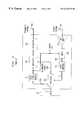
- FIG. 1there is shown an overall block diagram of an RF Tag system.
- An Application Processor 101communicates over Local Area Network (LAN) 102 to a plurality of Interrogators 103 - 104 .
- LANLocal Area Network
- Interrogators 103 - 104communicates over a plurality of Interrogators 103 - 104 .
- the Interrogatorsmay then each communicate with one or more of the Tags 105 a - 107 .
- the Interrogator 103receives an information signal, typically from Applications Processor 101 .
- the Interrogator 103takes this information signal and Processor 200 formats a Downlink message (Information Signal 200 a ) to be sent to the Tag.
- the information signal ( 200 a )may include data information such as information specifying which Tag is to respond (each Tag may have fixed or programmed identification number), instructions for the Tag's processor to execute such as activation and deactivation, and/or any other information to be used and/or stored by the Tag's processor.
- Radio Signal Source 201synthesizes a radio signal
- Modulator 202modulates the radio signal using Information Signal 200 a
- Transmitter 203transmits this modulated signal via Antenna 204 , illustratively using amplitude modulation, to a Tag.
- Amplitude modulationis a desirable choice because the Tag can demodulate such a signal with a single, inexpensive nonlinear device (such as a diode).
- many modulation schemesare possible such for example, as Phase Shift Keying (PSK) of the subcarrier (e.g., BPSK, QPSK), more complex modulation schemes (e.g., MSK, GMSK), etc.
- PSKPhase Shift Keying
- the reflecting antenna element 301 areceives the modulated signal.
- This signalis demodulated directly to baseband using the Detector/Modulator 302 which, illustratively, may be a single Schottky diode.
- the result of the diode detectoris essentially a demodulation of the incoming signal directly to baseband.
- the Information Signal 200 ais then amplified by Amplifier 303 , and bit synchronization is recovered in Clock Recovery Circuit 304 .
- Clock recovery circuitssuch as circuits that recover a clock from Manchester encoded data are well known in the art.
- frame synchronizationmay be implemented, as for example by detecting a predetermined bit pattern that indicates the start of a frame.
- the bit patternmay be detected by clock recovery circuit 304 or processor 305 ; bit pattern detection is well known in the art.
- the resulting information from clock recovery circuit 304is sent to a Processor 305 .
- Processor 305is typically an inexpensive 4 or 8 bit microprocessor and its associated memory, and it generates an Information Signal 306 from Tag 105 a back to the Interrogator (e.g., 103 ).
- Information Signal 306is sent to Detector/Modulator 302 to modulate the RF signal received by Tag 105 a to produce a modulated backscatter (i.e. reflected) signal.
- a Battery 310 or other power supplyprovides operating power to the circuitry of Tag 10 a . Power may also be received, for example, by using inductive coupling or microwaves.
- the Interrogator 103receives the reflected modulated signal through Receive Antenna 206 , amplifies the signal in a Low Noise Amplifier 207 , and demodulates the signal using homodyne detection in a Mixer 208 .
- a single antennamay replace Transmit antenna ( 204 ) and Receive Antenna ( 206 ), in which case an electronic method of canceling the transmitted signal from that received by the receiver chain is required.
- the Mixer 208then sends the Demodulated Signal 209 (if Mixer 208 is a Quadrature Mixer, it would send both I (in phase) and Q (quadrature) signals) to the Filter/Amplifier 210 .
- the resulting filtered signaltypically an Information Signal 213 is sent to a Processor 200 to determine the content of the message.
- RF Tagshave a single reflecting antenna. Since the Tag only reflects RF energy instead of generating it, an RF Tag is less expensive to manufacture and requires little battery power when operating. Consequently, an RF Tag provides a low cost arrangement and method of transmitting sensor measurements to a central processing system or operator for evaluation.
- the advantages of using RF Tags to transmit information to an Interrogatorare accompanied by a disadvantage: since the RF Tag is only a reflector, the signals returned from it are generally weaker than in systems that generate RF energy at both ends of the communications link.
- the signal-to-noise ratio (SNR) of a signal sent from the Tagfalls off rapidly (proportionally to r ⁇ 4 , where r is the distance between the transmitter and reflector).
- the SNR in each directionfalls off slowly (proportionally to r ⁇ 2 ).
- the interrogation range of the RF Tagis notably more limited by its distance from the RF transmitting source.
- FIG. 4depicts incoming RF radiation generated by RF Interrogator 103 and directed toward an RF Tag 105 a having a reflecting antenna element 301 a
- FIG. 5shows the reflectance of the RF Tag 105 a of FIG. 4 .
- the reflecting antenna 301 a of RF Tag 105 ais either in a fully reflecting mode or an essentially non-reflecting mode.
- reflecting antenna 301 a of RF Tag 105 ais only in the fully reflecting mode for half of each period T.
- the inventionsolves the above problems by providing two antenna elements axially aligned in a direction of expected incident radiation and spaced such that the echo signal of the second reflecting antenna element is 180° out of phase with the echo signal generated by the first reflecting antenna element.
- This 180° phase shiftcan be achieved, for example, by spacing the first and second reflecting antenna elements with respect to each other by a distance approximately equal to a quarter wavelength ( ⁇ fraction ( ⁇ /4+L ) ⁇ ) of the RF interrogating signal.
- the first and second reflecting antenna elementsare then alternately pulsed on and off such that while one reflecting antenna element is in the reflecting mode, the other reflecting antenna element is in the non-reflecting mode and vice versa. If the axis of the two antenna elements is oriented towards the Interrogator, the echoes reflected from the RF Tag will alternate by 180°, as will be shown in detail later.
- more than two antenna elementscan be provided in the RF Tag such that pairs of the antenna elements are alternately pulsed on and off, and the pair that provides the strongest reflection will be used for the current and future interrogations.
- FIG. 1is a block diagram of an illustrative prior art Radio Frequency Identification System to which the present invention is applicable;
- FIG. 2is a block diagram of an illustrative prior art Interrogator used in the RF Tag system of FIG. 1;
- FIG. 3 ais a block diagram of a prior art RF Tag used in the RFID system of FIG.
- FIG. 3 bis a block diagram of an RF Tag according to an embodiment of the present invention.
- FIG. 4is a block diagram representing a prior art reflecting antenna element (RF-Tag) system
- FIG. 5is a prior art timing diagram of the reflectivity of the single reflecting antenna element of FIG. 1;
- FIG. 6 ais a block diagram of an RF Tag containing two reflecting antenna elements according to an embodiment of the present invention.
- FIG. 6 bis a block diagram of an RF Tag containing three reflecting antenna elements according to another embodiment of the present invention.
- FIG. 6 cis a block diagram of an RF Tag containing four reflecting antenna elements according to yet another an embodiment of the present invention.
- FIG. 7 ais a timing diagram of the reflectivity of a first reflecting antenna element shown in FIG. 6;
- FIG. 7 bis a timing diagram of the reflectivity of a second reflecting antenna element shown in FIG. 6;
- FIG. 7 cis a graphical representation of the phase of the reflected signals in accordance with an embodiment of the present invention.
- FIG. 8is a graphical plot showing the signal level improvement provided by the reflecting antenna arrangement of the present invention.
- an RF Tag 105 bincludes a first antenna (reflecting) element 301 a and a second antenna (reflecting) element 301 b predeterminately disposed with respect to the first reflecting element 301 a such that the echo signal of second reflecting element 301 b is preferably 180° out of phase with the echo signal generated by first reflecting element 301 a
- This phase relationshipcan be achieved by positioning the second reflecting element 301 b 1 ⁇ 4 wavelength ( ⁇ /4) from the first reflecting element 301 a and then orienting the RF Tag so the axis of the two reflecting elements points towards the Interrogator.
- the axial alignment of the two reflecting elements in the direction of the expected incident radiationis required to achieve the 180° phase relationship and therefore a constructive interference.
- the axial alignment of the two antenna elementsis changed for any reason resulting in a change in the phase relationship of the respective echo signals is reduced to less than 60°, the desired constructive interference becomes destructive and the performance gain is lost.
- the amount of phase difference between the echo signal of the second reflecting element 301 b and the first reflecting element 301 acan be in a range of 60°-180°.
- the preferred 180° out-of phase relationship between the two reflecting elements 301 a and 301 bcan be obtained, for example, by positioning one reflecting element approximately 1 ⁇ 4 wavelength (of the interrogating signal) in front of the other in the direction from which the incident RF transmission is expected to arrive.
- this ⁇ fraction ( ⁇ /4+L ) ⁇ spacingis only one exemplary arrangement among many geometries that can be used to achieve the desired phase relationship between the two reflected signals. For example, spacings of 3 ⁇ 4 ⁇ , ⁇ fraction (5/4) ⁇ , ⁇ fraction (7/4) ⁇ can also achieve the 180° out-of-phase relationship.
- the two reflecting elements 301 a and 301 bare alternately pulsed on and off such that first reflecting element 301 a enters a reflecting state when second reflecting element 301 b enters a non-reflecting state, and vice versa. Care must be taken that both reflectors 301 a and 301 b are not simultaneously active because when both reflectors 301 a and 301 b are simultaneously active, and if both reflections are equally strong, the two reflected signals cancel each other out and provide no improvement in the interrogation range.
- the alternate pulsing of reflecting elements 301 a and 301 bis activated by processor 305 as instructed by the RF Interrogator in its initial transmission to the reflecting elements 301 a and 301 b .
- a bit stream of information containing coded instructions for the RF Tagsis sent to RF Tag 105 b such that the processor 305 recognizes that it has being interrogated (e.g., by recognizing its ID code).
- the initial transmission of the Interrogatorcan provide control information to the RF Tags and, more particularly, enables the selective activation and deactivation thereof.
- the processor 305places the RF Tag into its data read out mode.
- processor 305accomplishes this by switching the reflectivities of the reflector elements 301 a and 301 b alternately.
- the processor 305can accomplish this by setting the control lead to reflecting element 301 a to a logic one while setting the control lead of reflecting element 301 b to logic zero, and vice versa.
- processor 305can be pre-programmed to generate a square wave that is capable of alternately pulsing on and off the respective first and second reflecting antenna elements 301 a and 301 b .
- the RF tag 105 bwill usually be turned off, and upon receipt of the initial interrogating RF signal will be turned on. Once activated (i.e., turned on), the pre-programmed square wave will automatically generate the desired alternate pulsing of the reflecting antenna elements.
- the continuous wave (CW) transmissionbegins to cause RF Tag 105 b to reflect information relating to the data set or data measurements stored in or sensed by the RF Tag.
- the alternate pulsing of reflecting elements 301 a and 301 bchanges the phase of the reflected signal by 180° because the incident signal traverses a round-trip path that is a total of one-half a wavelength longer (i.e. twice the ⁇ fraction ( ⁇ / 4 +L ) ⁇ spacing of the reflecting elements) than that of single reflector prior art systems.
- the change in phase of the reflected signalresults in a 6 dB improvement in the signal-to-noise ratio (SNR) as compared with the single reflecting element configuration of FIG.
- SNRsignal-to-noise ratio
- the 6 dB improvementcan be achieved when the two reflecting elements 10 and 12 are spaced approximately 1 ⁇ 4 wavelength apart and reflect equally strongly in the direction of reflection. If this is not the case, an improvement that is less than a 6 dB will be achieved until the spacing becomes less than ⁇ fraction ( ⁇ / 12 +L ) ⁇ in the direction of the incident signal, which would result in a configuration whose performance is worse than that of the single reflector of the prior art.
- reflecting elements 301 a and 301 b depicted in FIG. 6 aare disposed on the same Tag. Accordingly the reflecting elements 301 a , 301 b and 301 c , and 301 a , 301 b , 310 c and 301 d of FIGS. 6 b and 6 c , respectively, are embodied on the same Tag. It is contemplated herein to include the added reflecting elements for increasing the interrogation range of the RF Tag separately from the RF Tag such that they can be added to an existing RF Tag without requiring modification of the same.
- the added reflecting elementsare also disposed in spaced relation with the single reflecting element of the RF Tag such that they are ⁇ fraction ( ⁇ /4+L ) ⁇ apart in the direction of the expected incident radiation so as to achieve the desired 180° phase shift in reflected signals.
- the added reflecting elementsare also disposed in spaced relation with the single reflecting element of the RF Tag such that they are ⁇ fraction ( ⁇ /4+L ) ⁇ apart in the direction of the expected incident radiation so as to achieve the desired 180° phase shift in reflected signals.
- ⁇ fraction ( ⁇ /4+L ) ⁇ apartin the direction of the expected incident radiation so as to achieve the desired 180° phase shift in reflected signals.
- FIG. 7 adepicts the reflectance of the first reflecting element 301 a and FIG. 7 b depicts the reflectance of the second reflecting element 301 b .
- FIG. 7 bdepicts the reflectance of the second reflecting element 301 b .
- the reflected signalcan be represented as a carrier sinusoid modulating (i.e. multiplying) the Fourier Series of the square wave in FIG. 1 :
- Equation (2)represents the higher-order terms of this series, which is shown for an ideal square wave.
- the coefficients of the Fourier Series for a less-than-ideal square wavewill somewhat deviate from these coefficients to a degree, but such deviations will not change the results of the present analysis.
- the reflected signal picked up by the receive antenna 206 and amplified by the low-noise amplifier 207is demodulated by the mixer 208 using the RF source 214 (homodyne detection). This demodulation eliminates the cos( ⁇ ct) factor from equation (1). Consequently, the only surviving part of equation (1) in the signal presented to the filter-amplifier 210 is the Fourier series F(t).
- the filter-amplifier 210is an AC-coupled lowpass filter that suppresses direct current (DC) frequencies, passes frequencies around the carrier frequency 1 T ⁇ ⁇ Hz ,
- the filtered signalcan be further demodulated to extract information that was modulated onto it as described elsewhere.
- the square wave of reflection for the two-reflector systemhas twice the amplitude of the single-reflector system, because (i) the RF-Tag is reflecting constantly, and (ii) alternate reflections have a 180° phase difference.
- the following mathematical analysisshows this for the general case in which the phase angle of the reflections from the second reflecting-element 301 b differ from those of first element 301 a by ⁇ radians, so that the total signal reflected by both elements is
- reflected_signal two — reflectorF ( t )cos ⁇ c t +(1 ⁇ F ( t ))(cos( ⁇ c t+ ⁇ )) (4)
- F(t)is the Fourier series defined in equation (2). It will be noted that 1 ⁇ F(t) assumes the same two values (0 for no reflectance and 1 for full reflectance) as F(t) assumes, and also that 1 ⁇ F(t) is 0 when F(t) is 1, and vice versa. Collecting terms and using the usual trigonometric identity for cos( ⁇ c t+p) produces the equivalent expression
- reflected_signal two — reflectorcos( ⁇ ct + ⁇ )+ F ( t )((1 ⁇ cos( ⁇ ))cos( ⁇ ct )+sin( ⁇ )sin( ⁇ ct )) (5)
- the signalis demodulated by the mixer 208 .
- filtered_signal two_reflector4 ⁇ ⁇ sin ⁇ ( 2 ⁇ ⁇ ⁇ ⁇ t T ) ( 8 )
- the 6 dB improvementcan be achieved when the two reflecting elements 301 a and 301 b are spaced approximately 1 ⁇ 4 wavelength apart and reflect equally strongly in the direction of reflection. If this is not the case, an improvement that is less than a 6 dB but greater than 0 dB will be achieved provided that the spacing is greater than ⁇ fraction ( ⁇ / 12 +L ) ⁇ in the direction of the incident signal. If the spacing is less than ⁇ fraction ( ⁇ / 12 +L ) ⁇ in the direction of the incident signal, the performance is worse than that of the single reflector of the prior art.
- Equation (8)shows that two reflectors perform better than one reflector if the phase difference ⁇ is greater than 60°, which corresponds to a separation of approximately ⁇ 12
- the graph of FIG. 8shows the variation in reflected signal as the angle between the axis of the two reflecting elements becomes mis-aligned with the direction of the incoming RF radiation. Specifically, this graph plots 20 log 10 (2 sin ( ⁇ fraction ( ⁇ /2+L ) ⁇ cos()) in dB versus the misalignment angle in degrees.
- FIG. 8implies that the two-reflector configuration is superior to the one-reflector configuration if the misalignment angle is less than 70°.
- an RF-Tag systemcan be oriented so that the two reflecting elements are positioned approximately 1 ⁇ 4 wavelength apart in the direction of reflection.
- an RF-Tagcan be positioned in a predictable orientation to an interrogation device with a directional antenna mounted in or on a vehicle driven past the parking meter.
- the simplest method of coping with a misalignment angle greater than 70°is simply to pulse both reflecting antenna elements 301 a and 301 b on and off together simultaneously, so that both are on or off at the same time. This causes the reflections from both elements to add together constructively, with the result that the reflected signal is enhanced from 3.5 dB to 6 dB above the single-reflector prior-art embodiment of FIG. 3 a.
- a strategy for utilizing thisis for both reflecting antenna elements 301 a and 301 b to pulse first alternately on and off, followed by pulsing both on and off simultaneously for an equally long interval.
- a messagewould be modulated onto the subcarrier in duplicate, i.e. once in the first interval, and again in the second interval. If Interrogator 103 receives both copies of the message, it would simply discard the duplicate message.
- An alternative strategyis for the Interrogator 103 to pick up the pulsed reflections from the first and second intervals and to identify the interval that generated the strongest reflection.
- the Interrogatorwill send a message to the Processor 305 of the RF Tag designating the stronger interval, so that the Processor 305 can use the appropriate mode (i.e. alternating or simultaneous pulsing) to send the message(s) to the Interrogator 103 .
- FIG. 6 bshows a block diagram of RF tag 105 c having three reflecting antenna elements 301 a , 301 b and 301 c arranged in a triangular array.
- the processor 305would be pre-programmed to make the three elements 301 a , 301 b and 301 c pulse alternately in pairs—first elements 301 a and 301 b , then 301 b and 301 c , and finally 301 c and 301 a for predetermined intervals of time. If the message to be returned from the RF tag 105 c is short enough, the tag will simply send the message three times by modulating the pulses from each of the three pairs.
- the Interrogator 103If the Interrogator 103 receives a signal reflected from at least one of the pairs, the Interrogator 103 will demodulate that signal to obtain the message, which can be validated with the aid of an error-detecting code. If the Interrogator 103 receives more than one valid copy of the message, it will discard the duplicate message(s).
- each of the three pairssequentially will produce a short burst of message-free pulsing.
- the Interrogator 103will pick up the pulsed reflections from the three pairs and will identify the pair that generated the strongest reflection.
- the Interrogatorwill send a message to the Processor 305 of the RF Tag designating the pair that produced the strongest reflection, so that the Processor 305 can direct that pair to send the message to the Interrogator 103 .
- FIG. 6 cshows another embodiment of the present invention utilizing four reflecting antenna elements 301 a , 301 b , 301 c and 301 d arranged in a tetrahedral type configuration.
- elements 301 a - 301 dwill be alternately pulsed in pairs, and the pair that delivers the strongest reflection will be used by the system.
- element pairs 301 a and 301 b , 301 b and 301 c , 301 c and 301 d , 301 d and 301 a , 301 a and 301 c , and 301 b and 301 dwill be each alternately pulsed for a predetermined time interval.
- a short messagecan be resent in sextuplicate, once by each pair.
- each of these six pairssequentially will produce a short burst of message-free pulsing.
- the InterrogatorAfter identifying the pair producing the strongest reflection, the Interrogator will send a message to the Processor 305 of the RF Tag designating that pair, so that the Processor 305 can direct that pair to send the message to the Interrogator 103 .
- a Luneberg lens generalization of the multiple-element approach of the previous sectionis capable of providing almost perfect resistance to misalignment of the element axis with the direction of reflection.
- U.S. Pat. No. 3,703,723, titled Portable Passive Reflector, of Victor Albanese et. al. and incorporated herein by referencedescribes a Luneberg lens system in which a reflecting net is positioned on one side of a spherical lens (which is sometimes implemented as a hemisphere with a reflecting bottom). The reflectivity of this net is pulsed on and off in a manner similar to the antenna element of a conventional RF Tag.
- the benefits of using a Luneberg lensinclude 1) an increase in the SNR by increasing the radar cross-section of the lens, and 2) provision of a very wide range of angles (with respect to the direction of the incoming RF radiation) over which the lens will function.
- the lens of the '971 patentis spherical having void dielectric and density correction.
- the density of the dielectric material forming the spherical lensis changed by reducing the dielectric structure by removal of the dielectric material, thereby leaving voids in the dielectric structure.
- the spherical lensis assembled by stacking circular plates of the void-containing dielectric material where the plates vary in diameter from a maximum in the middle of the structure toward each end thereof
- the voids in the dielectric platesare staggered or offset with respect to each other except at the centers of the plates where the voids are aligned to facilitate the passage of an assembly member.
- the platesare then subject to pressure molding to secure the aligned position.
- the Luneberg lens system described by Albanese et al.includes a diode array whose pulsing modulates the effective cross section, and thus the strength of the returned signal.
- a second set of reflecting elementscan be placed at a radius from the diode array approximately 1 ⁇ 4 wavelength greater than the radius of the first set. If the reflectivities of the two shells of reflecting elements are alternately pulsed in accordance with the invention as above, the Luneberg lens system will operate in binary phase-shift key mode (BPSK) mode to provide up to 6 dB of improvement in the SNR.
- BPSKbinary phase-shift key mode
- This arrangement in accordance with the present inventionmay also be applied to the version of the Luneberg lens in which the sphere is bisected and the resulting flat surface is made reflective.
- the Luneberg lenscan function over nearly r steradians of solid angle.
- This listincludes BPSK, QPSK, and more complex modulation schemes (e.g., MSK, GMSK, etc.) These modulation techniques are generally sufficient for use with an RF Tag system implemented in accordance with the present invention.
Landscapes
- Engineering & Computer Science (AREA)
- Physics & Mathematics (AREA)
- Automation & Control Theory (AREA)
- General Physics & Mathematics (AREA)
- Computer Security & Cryptography (AREA)
- Electromagnetism (AREA)
- Signal Processing (AREA)
- Artificial Intelligence (AREA)
- Computer Vision & Pattern Recognition (AREA)
- Theoretical Computer Science (AREA)
- Near-Field Transmission Systems (AREA)
Abstract
Description


Claims (31)
Priority Applications (3)
| Application Number | Priority Date | Filing Date | Title |
|---|---|---|---|
| US09/421,867US6236315B1 (en) | 1999-10-19 | 1999-10-19 | Method and apparatus for improving the interrogation range of an RF tag |
| US09/801,519US20010010495A1 (en) | 1999-10-19 | 2001-03-08 | Method and apparatus for improving the interrogation range of an RF-Tag |
| US09/999,390US6590498B2 (en) | 1999-10-19 | 2001-10-31 | Method and apparatus for improving the interrogation range of an RF-Tag |
Applications Claiming Priority (1)
| Application Number | Priority Date | Filing Date | Title |
|---|---|---|---|
| US09/421,867US6236315B1 (en) | 1999-10-19 | 1999-10-19 | Method and apparatus for improving the interrogation range of an RF tag |
Related Child Applications (1)
| Application Number | Title | Priority Date | Filing Date |
|---|---|---|---|
| US09/801,519ContinuationUS20010010495A1 (en) | 1999-10-19 | 2001-03-08 | Method and apparatus for improving the interrogation range of an RF-Tag |
Publications (1)
| Publication Number | Publication Date |
|---|---|
| US6236315B1true US6236315B1 (en) | 2001-05-22 |
Family
ID=23672386
Family Applications (2)
| Application Number | Title | Priority Date | Filing Date |
|---|---|---|---|
| US09/421,867Expired - LifetimeUS6236315B1 (en) | 1999-10-19 | 1999-10-19 | Method and apparatus for improving the interrogation range of an RF tag |
| US09/801,519AbandonedUS20010010495A1 (en) | 1999-10-19 | 2001-03-08 | Method and apparatus for improving the interrogation range of an RF-Tag |
Family Applications After (1)
| Application Number | Title | Priority Date | Filing Date |
|---|---|---|---|
| US09/801,519AbandonedUS20010010495A1 (en) | 1999-10-19 | 2001-03-08 | Method and apparatus for improving the interrogation range of an RF-Tag |
Country Status (1)
| Country | Link |
|---|---|
| US (2) | US6236315B1 (en) |
Cited By (63)
| Publication number | Priority date | Publication date | Assignee | Title |
|---|---|---|---|---|
| US20020015436A1 (en)* | 1998-04-24 | 2002-02-07 | Ovard David K. | Modulators, transmitters, a radio frequency identification device system and carrier signal suppression methods |
| US6509836B1 (en)* | 2000-03-31 | 2003-01-21 | Georgia Tech Research Corporation | Smart reflection antenna system and method |
| US20030097302A1 (en)* | 2001-11-21 | 2003-05-22 | Overhultz Gary L. | Advertising compliance monitoring system |
| US20030137403A1 (en)* | 2001-10-09 | 2003-07-24 | Carrender Curtis L. | Methods and apparatuses for identification |
| WO2003040950A3 (en)* | 2001-11-02 | 2003-09-18 | Avid Identification Syst Inc | Dual antenna coil transponder system |
| US6650254B1 (en) | 2000-03-13 | 2003-11-18 | Ergodex | Computer input device with individually positionable and programmable switches |
| US20040043747A1 (en)* | 2002-06-04 | 2004-03-04 | Forster Ian J. | Reflective communication using radio-frequency devices |
| US20040046016A1 (en)* | 2002-09-05 | 2004-03-11 | Honeywell International Inc. | Rfid tag having multiple transceivers |
| US6707376B1 (en) | 2002-08-09 | 2004-03-16 | Sensormatic Electronics Corporation | Pulsed power method for increased read range for a radio frequency identification reader |
| US20040066279A1 (en)* | 2002-10-02 | 2004-04-08 | Hughes Michael A. | RFID system and method including tag ID compression |
| US20040066281A1 (en)* | 2002-10-02 | 2004-04-08 | Hughes Michael A. | System and method to identify multiple RFID tags |
| US20040150521A1 (en)* | 2003-02-03 | 2004-08-05 | Stilp Louis A. | RFID based security system |
| US20040160322A1 (en)* | 2003-02-03 | 2004-08-19 | Stilp Louis A. | RFID reader for a security system |
| US20040160323A1 (en)* | 2003-02-03 | 2004-08-19 | Stilp Louis A. | RFID transponder for a security system |
| US20040160309A1 (en)* | 2003-02-03 | 2004-08-19 | Stilp Louis A. | Communications control in a security system |
| US20040160306A1 (en)* | 2003-02-03 | 2004-08-19 | Stilp Louis A. | Device enrollment in a security system |
| US20040160324A1 (en)* | 2003-02-03 | 2004-08-19 | Stilp Louis A. | Controller for a security system |
| US20040198222A1 (en)* | 2002-10-02 | 2004-10-07 | Emre Ertin | Method of simultaneously reading multiple radio frequency tags, RF tags, and RF reader |
| US20040215750A1 (en)* | 2003-04-28 | 2004-10-28 | Stilp Louis A. | Configuration program for a security system |
| US20040212494A1 (en)* | 2003-02-03 | 2004-10-28 | Stilp Louis A. | Cordless telephone system |
| US20040212497A1 (en)* | 2003-02-03 | 2004-10-28 | Stilp Louis A. | Multi-controller security network |
| US20040212493A1 (en)* | 2003-02-03 | 2004-10-28 | Stilp Louis A. | RFID reader for a security network |
| US20040212500A1 (en)* | 2003-02-03 | 2004-10-28 | Stilp Louis A. | RFID based security network |
| US20050000787A1 (en)* | 2002-09-19 | 2005-01-06 | Rix Scott M. | Independently positionable and programmable key switches |
| US6842106B2 (en) | 2002-10-04 | 2005-01-11 | Battelle Memorial Institute | Challenged-based tag authentication model |
| US20050006466A1 (en)* | 2001-11-21 | 2005-01-13 | Overhultz Gary L. | Advertising compliance monitoring system |
| US20050017073A1 (en)* | 2003-06-13 | 2005-01-27 | Xtec, Incorporated | Differential radio frequency identification reader |
| US20050052287A1 (en)* | 2001-09-13 | 2005-03-10 | Whitesmith Howard William | Wireless communication system |
| US20050084003A1 (en)* | 2003-10-21 | 2005-04-21 | Mark Duron | Full-duplex radio frequency echo cancellation |
| US20050114326A1 (en)* | 2003-11-07 | 2005-05-26 | Smith John S. | Methods and apparatuses to identify devices |
| US6956472B1 (en) | 2003-04-28 | 2005-10-18 | Walcott Jr James D | Auto hang tag with radio transponder |
| US20050263591A1 (en)* | 2003-08-09 | 2005-12-01 | Smith John S | Methods and apparatuses to identify devices |
| US20060001528A1 (en)* | 2004-07-01 | 2006-01-05 | Zvi Nitzan | Battery-assisted backscatter RFID transponder |
| US20060108421A1 (en)* | 2003-12-03 | 2006-05-25 | Becker Robert C | RFID tag having multiple transceivers |
| US20060132303A1 (en)* | 2003-02-03 | 2006-06-22 | Stilp Louis A | Component diversity in a RFID security network |
| US20060132302A1 (en)* | 2003-02-03 | 2006-06-22 | Stilp Louis A | Power management of transponders and sensors in an RFID security network |
| US20060145842A1 (en)* | 2003-02-03 | 2006-07-06 | Stilp Louis A | Multi-level meshed security network |
| US20070008140A1 (en)* | 2005-06-14 | 2007-01-11 | Mikko Saarisalo | Tag multiplication |
| US20070139164A1 (en)* | 1996-05-13 | 2007-06-21 | O'toole James E | Radio frequency data communications device |
| US20070206704A1 (en)* | 2006-03-03 | 2007-09-06 | Applied Wireless Identification Group, Inc. | RFID reader with adaptive carrier cancellation |
| US7280045B2 (en) | 2005-06-14 | 2007-10-09 | Nokia Corporation | Machine-readable tag, selectable extension antennas for use therewith, and display structure having such tag |
| US20070262851A1 (en)* | 2001-05-31 | 2007-11-15 | Stewart Roger G | Methods and apparatuses to identify devices |
| US7310070B1 (en) | 2006-08-23 | 2007-12-18 | Goliath Solutions, Llc | Radio frequency identification shelf antenna with a distributed pattern for localized tag detection |
| US20080001734A1 (en)* | 2003-02-03 | 2008-01-03 | Stilp Louis A | Portable telephone in a security network |
| US7374096B2 (en) | 2001-11-21 | 2008-05-20 | Goliath Solutions, Llc | Advertising compliance monitoring system |
| US20080182512A1 (en)* | 2007-01-25 | 2008-07-31 | Hewlett-Packard Development Company, L.P. | Apparatus For And Method of Selecting Between Antennas For Wireless Communication |
| US20080272890A1 (en)* | 2005-06-30 | 2008-11-06 | Zvi Nitzan | Battery-assisted backscatter RFID transponder |
| US20090002171A1 (en)* | 2007-06-18 | 2009-01-01 | Petronella Norberg | Device and method for capacitive reading of a code |
| US20090045916A1 (en)* | 2005-06-30 | 2009-02-19 | Zvi Nitzan | Battery-assisted backscatter RFID transponder |
| US7532114B2 (en) | 2003-02-03 | 2009-05-12 | Ingrid, Inc. | Fixed part-portable part communications network for a security network |
| US20090243813A1 (en)* | 2008-03-25 | 2009-10-01 | Smith Joshua R | Wireless programming of non-volatile memory with near-field uhf coupling |
| US7760835B2 (en) | 2002-10-02 | 2010-07-20 | Battelle Memorial Institute | Wireless communications devices, methods of processing a wireless communication signal, wireless communication synchronization methods and a radio frequency identification device communication method |
| US20110156874A1 (en)* | 2009-12-29 | 2011-06-30 | National Taiwan University Of Science & Technology | RFID Tags, RFIG Transmission Methods And RFID Devices |
| CN102194268A (en)* | 2010-03-17 | 2011-09-21 | Ls产电株式会社 | Gate system |
| US20130307763A1 (en)* | 2012-05-21 | 2013-11-21 | Amplifier Research Corporation | Field analyzer |
| US20140152499A1 (en)* | 2012-02-28 | 2014-06-05 | Physical Devices Llc | Methods, systems, and computer readable media for mitigation of in-band interference of global positioning system (gps) signals |
| US20140179223A1 (en)* | 2012-12-26 | 2014-06-26 | Nxp B.V. | Wireless power and data transmission |
| US20150168535A1 (en)* | 2012-07-06 | 2015-06-18 | Siemens Aktiengesellschaft | Method and Arrangement for the Relative Position Detection of Stations by Means of Radio Location |
| US20150256969A1 (en)* | 2005-06-16 | 2015-09-10 | Koninklijke Philips N.V. | Tracking rfid objects with integrated communication link |
| US9350401B2 (en) | 2010-08-30 | 2016-05-24 | Physical Devices, Llc | Tunable filter devices and methods |
| US9450625B2 (en) | 2010-08-30 | 2016-09-20 | Physical Devices, Llc | Methods, systems, and non-transitory computer readable media for wideband frequency and bandwidth tunable filtering |
| US9866267B2 (en) | 2014-02-21 | 2018-01-09 | Physical Devices, Llc | Devices and methods for diversity signal enhancement and cosite cancellation |
| US20220027581A1 (en)* | 2020-07-27 | 2022-01-27 | Nxp B.V. | Rfid transponder having modifiable settings |
Families Citing this family (14)
| Publication number | Priority date | Publication date | Assignee | Title |
|---|---|---|---|---|
| US6763315B2 (en) | 2000-11-29 | 2004-07-13 | Ensure Technologies, Inc. | Method of securing access to a user having an enhanced security proximity token |
| US20070273476A1 (en)* | 2004-03-26 | 2007-11-29 | Semiconductor Energy Laboratory Co., Ltd. | Thin Semiconductor Device And Operation Method Of Thin Semiconductor Device |
| CN101176013A (en)* | 2004-08-12 | 2008-05-07 | 威尔网公司 | System and method for tracking containers in grounded marine terminal operations |
| JP4407720B2 (en)* | 2006-06-09 | 2010-02-03 | 日本電気株式会社 | Wireless communication system and wireless communication method |
| US7755541B2 (en)* | 2007-02-13 | 2010-07-13 | Wherenet Corp. | System and method for tracking vehicles and containers |
| US9880283B2 (en)* | 2007-02-13 | 2018-01-30 | Zih Corp. | System, apparatus and method for locating and/or tracking assets |
| WO2013173250A1 (en) | 2012-05-13 | 2013-11-21 | Invention Mine Llc | Full duplex wireless transmission with self-interference cancellation |
| US10177896B2 (en) | 2013-05-13 | 2019-01-08 | Amir Keyvan Khandani | Methods for training of full-duplex wireless systems |
| US9236996B2 (en) | 2013-11-30 | 2016-01-12 | Amir Keyvan Khandani | Wireless full-duplex system and method using sideband test signals |
| US9820311B2 (en) | 2014-01-30 | 2017-11-14 | Amir Keyvan Khandani | Adapter and associated method for full-duplex wireless communication |
| US10333593B2 (en) | 2016-05-02 | 2019-06-25 | Amir Keyvan Khandani | Systems and methods of antenna design for full-duplex line of sight transmission |
| US10700766B2 (en) | 2017-04-19 | 2020-06-30 | Amir Keyvan Khandani | Noise cancelling amplify-and-forward (in-band) relay with self-interference cancellation |
| US11057204B2 (en) | 2017-10-04 | 2021-07-06 | Amir Keyvan Khandani | Methods for encrypted data communications |
| US11012144B2 (en) | 2018-01-16 | 2021-05-18 | Amir Keyvan Khandani | System and methods for in-band relaying |
Citations (3)
| Publication number | Priority date | Publication date | Assignee | Title |
|---|---|---|---|---|
| US3703723A (en) | 1970-01-09 | 1972-11-21 | Grumman Aerospace Corp | Portable passive reflector |
| US5649296A (en)* | 1995-06-19 | 1997-07-15 | Lucent Technologies Inc. | Full duplex modulated backscatter system |
| US5842118A (en)* | 1996-12-18 | 1998-11-24 | Micron Communications, Inc. | Communication system including diversity antenna queuing |
- 1999
- 1999-10-19USUS09/421,867patent/US6236315B1/ennot_activeExpired - Lifetime
- 2001
- 2001-03-08USUS09/801,519patent/US20010010495A1/ennot_activeAbandoned
Patent Citations (3)
| Publication number | Priority date | Publication date | Assignee | Title |
|---|---|---|---|---|
| US3703723A (en) | 1970-01-09 | 1972-11-21 | Grumman Aerospace Corp | Portable passive reflector |
| US5649296A (en)* | 1995-06-19 | 1997-07-15 | Lucent Technologies Inc. | Full duplex modulated backscatter system |
| US5842118A (en)* | 1996-12-18 | 1998-11-24 | Micron Communications, Inc. | Communication system including diversity antenna queuing |
Cited By (145)
| Publication number | Priority date | Publication date | Assignee | Title |
|---|---|---|---|---|
| US20070139164A1 (en)* | 1996-05-13 | 2007-06-21 | O'toole James E | Radio frequency data communications device |
| US7545256B2 (en) | 1996-05-13 | 2009-06-09 | Keystone Technology Solutions, Llc | System and method for identifying a radio frequency identification (RFID) device |
| US20080180253A1 (en)* | 1998-04-24 | 2008-07-31 | Micron Technology, Inc. | RFID Communication System and Method of Operation |
| US20110140858A1 (en)* | 1998-04-24 | 2011-06-16 | Ovard David K | Methods and apparatus for rfid tag communications |
| US20070290810A1 (en)* | 1998-04-24 | 2007-12-20 | Ovard David K | Backscatter interrogators, communication systems and backscatter communication methods |
| US20070290808A1 (en)* | 1998-04-24 | 2007-12-20 | Ovard David K | Backscatter interrogators, communication systems and backscatter communication methods |
| US8855169B2 (en) | 1998-04-24 | 2014-10-07 | Round Rock Research, Llc | Methods and apparatus for RFID tag communications |
| US20020015436A1 (en)* | 1998-04-24 | 2002-02-07 | Ovard David K. | Modulators, transmitters, a radio frequency identification device system and carrier signal suppression methods |
| US6650254B1 (en) | 2000-03-13 | 2003-11-18 | Ergodex | Computer input device with individually positionable and programmable switches |
| US6509836B1 (en)* | 2000-03-31 | 2003-01-21 | Georgia Tech Research Corporation | Smart reflection antenna system and method |
| US8284034B2 (en) | 2001-05-31 | 2012-10-09 | Alien Technology Corporation | Methods and apparatuses to identify devices |
| US20070262851A1 (en)* | 2001-05-31 | 2007-11-15 | Stewart Roger G | Methods and apparatuses to identify devices |
| US20050052287A1 (en)* | 2001-09-13 | 2005-03-10 | Whitesmith Howard William | Wireless communication system |
| US7408456B2 (en)* | 2001-09-13 | 2008-08-05 | Tagtec Limited | Wireless communication system |
| US7193504B2 (en)* | 2001-10-09 | 2007-03-20 | Alien Technology Corporation | Methods and apparatuses for identification |
| US8279047B2 (en) | 2001-10-09 | 2012-10-02 | Alien Technology Corporation | Methods and apparatus for anti-collision for radio frequency communication |
| US20030137403A1 (en)* | 2001-10-09 | 2003-07-24 | Carrender Curtis L. | Methods and apparatuses for identification |
| US20070013484A1 (en)* | 2001-10-09 | 2007-01-18 | Curt Carrender | Methods and apparatuses for identification |
| WO2003040950A3 (en)* | 2001-11-02 | 2003-09-18 | Avid Identification Syst Inc | Dual antenna coil transponder system |
| US20050087599A1 (en)* | 2001-11-02 | 2005-04-28 | Ward William H. | Dual antenna coil transponder system |
| US7347379B2 (en) | 2001-11-02 | 2008-03-25 | Avid Identification Systems, Inc. | Dual antenna coil transponder system |
| US20050095573A1 (en)* | 2001-11-21 | 2005-05-05 | Overhultz Gary L. | Advertising compliance monitoring system |
| US20080197193A1 (en)* | 2001-11-21 | 2008-08-21 | Overhultz Gary L | Advertising Compliance Monitoring System |
| US7549579B2 (en) | 2001-11-21 | 2009-06-23 | Goliath Solutions, Llc | Advertising compliance monitoring system |
| US20030097302A1 (en)* | 2001-11-21 | 2003-05-22 | Overhultz Gary L. | Advertising compliance monitoring system |
| US6837427B2 (en) | 2001-11-21 | 2005-01-04 | Goliath Solutions, Llc. | Advertising compliance monitoring system |
| US7374096B2 (en) | 2001-11-21 | 2008-05-20 | Goliath Solutions, Llc | Advertising compliance monitoring system |
| US6951305B2 (en) | 2001-11-21 | 2005-10-04 | Goliath Solutions, Llc. | Advertising compliance monitoring system |
| US20050006466A1 (en)* | 2001-11-21 | 2005-01-13 | Overhultz Gary L. | Advertising compliance monitoring system |
| US7021535B2 (en) | 2001-11-21 | 2006-04-04 | Goliath Solutions, Llc | Advertising compliance monitoring system |
| US7844221B2 (en) | 2002-06-04 | 2010-11-30 | Forster Ian J | Reflective communication using radio-frequency devices |
| US20070077888A1 (en)* | 2002-06-04 | 2007-04-05 | Mineral Lassen Llc | Reflective communication using radio-frequency devices |
| US20100151892A1 (en)* | 2002-06-04 | 2010-06-17 | Forster Ian J | Reflective communication using radio-frequency devices |
| US20080043820A1 (en)* | 2002-06-04 | 2008-02-21 | Mineral Lassen Llc | Reflective communication using radio-frequency devices |
| US7970353B2 (en) | 2002-06-04 | 2011-06-28 | Mineral Lassen Llc | Reflective communication using radio-frequency devices |
| US7630684B2 (en) | 2002-06-04 | 2009-12-08 | Forster Ian J | Reflective communication using radio-frequency devices |
| US7697946B2 (en) | 2002-06-04 | 2010-04-13 | Forster Ian J | Reflective communication using radio-frequency devices |
| US20040043747A1 (en)* | 2002-06-04 | 2004-03-04 | Forster Ian J. | Reflective communication using radio-frequency devices |
| US20080045150A1 (en)* | 2002-06-04 | 2008-02-21 | Mineral Lassen Llc | Reflective communication using radio-frequency devices |
| US6707376B1 (en) | 2002-08-09 | 2004-03-16 | Sensormatic Electronics Corporation | Pulsed power method for increased read range for a radio frequency identification reader |
| US20040046016A1 (en)* | 2002-09-05 | 2004-03-11 | Honeywell International Inc. | Rfid tag having multiple transceivers |
| US20040074976A1 (en)* | 2002-09-05 | 2004-04-22 | Becker Robert C. | RFID tag having multiple transceivers |
| US6726099B2 (en)* | 2002-09-05 | 2004-04-27 | Honeywell International Inc. | RFID tag having multiple transceivers |
| US7156312B2 (en) | 2002-09-05 | 2007-01-02 | Honeywell International Inc. | RFID tag having multiple transceivers |
| US20070108034A1 (en)* | 2002-09-19 | 2007-05-17 | Ergodex, Inc. | Independently positionable and programmable key switches |
| US20050000787A1 (en)* | 2002-09-19 | 2005-01-06 | Rix Scott M. | Independently positionable and programmable key switches |
| US6903662B2 (en) | 2002-09-19 | 2005-06-07 | Ergodex | Computer input device with individually positionable and programmable input members |
| US7157651B2 (en) | 2002-09-19 | 2007-01-02 | Ergodex, Inc. | Independently positionable and programmable key switches |
| US6995655B2 (en) | 2002-10-02 | 2006-02-07 | Battelle Memorial Institute | Method of simultaneously reading multiple radio frequency tags, RF tags, and RF reader |
| US20040198222A1 (en)* | 2002-10-02 | 2004-10-07 | Emre Ertin | Method of simultaneously reading multiple radio frequency tags, RF tags, and RF reader |
| US7760835B2 (en) | 2002-10-02 | 2010-07-20 | Battelle Memorial Institute | Wireless communications devices, methods of processing a wireless communication signal, wireless communication synchronization methods and a radio frequency identification device communication method |
| US7009495B2 (en) | 2002-10-02 | 2006-03-07 | Battelle Memorial Institute | System and method to identify multiple RFID tags |
| US8218703B2 (en) | 2002-10-02 | 2012-07-10 | Battelle Memorial Institute | Methods of processing a wireless communication signal, wireless communication synchronization methods, and a radio frequency identification device communication method |
| US20040066281A1 (en)* | 2002-10-02 | 2004-04-08 | Hughes Michael A. | System and method to identify multiple RFID tags |
| US7009526B2 (en) | 2002-10-02 | 2006-03-07 | Battelle Memorial Institute | RFID system and method including tag ID compression |
| US20040066279A1 (en)* | 2002-10-02 | 2004-04-08 | Hughes Michael A. | RFID system and method including tag ID compression |
| US6842106B2 (en) | 2002-10-04 | 2005-01-11 | Battelle Memorial Institute | Challenged-based tag authentication model |
| US7283048B2 (en) | 2003-02-03 | 2007-10-16 | Ingrid, Inc. | Multi-level meshed security network |
| US7202789B1 (en) | 2003-02-03 | 2007-04-10 | Ingrid, Inc. | Clip for RFID transponder of a security network |
| US20060145842A1 (en)* | 2003-02-03 | 2006-07-06 | Stilp Louis A | Multi-level meshed security network |
| US7079034B2 (en) | 2003-02-03 | 2006-07-18 | Ingrid, Inc. | RFID transponder for a security system |
| US7079020B2 (en) | 2003-02-03 | 2006-07-18 | Ingrid, Inc. | Multi-controller security network |
| US7084756B2 (en) | 2003-02-03 | 2006-08-01 | Ingrid, Inc. | Communications architecture for a security network |
| US7511614B2 (en) | 2003-02-03 | 2009-03-31 | Ingrid, Inc. | Portable telephone in a security network |
| US7091827B2 (en) | 2003-02-03 | 2006-08-15 | Ingrid, Inc. | Communications control in a security system |
| US7119658B2 (en) | 2003-02-03 | 2006-10-10 | Ingrid, Inc. | Device enrollment in a security system |
| US20060132302A1 (en)* | 2003-02-03 | 2006-06-22 | Stilp Louis A | Power management of transponders and sensors in an RFID security network |
| US20060132303A1 (en)* | 2003-02-03 | 2006-06-22 | Stilp Louis A | Component diversity in a RFID security network |
| US20040160324A1 (en)* | 2003-02-03 | 2004-08-19 | Stilp Louis A. | Controller for a security system |
| US7057512B2 (en) | 2003-02-03 | 2006-06-06 | Ingrid, Inc. | RFID reader for a security system |
| US7495544B2 (en) | 2003-02-03 | 2009-02-24 | Ingrid, Inc. | Component diversity in a RFID security network |
| US7019639B2 (en) | 2003-02-03 | 2006-03-28 | Ingrid, Inc. | RFID based security network |
| US7042353B2 (en) | 2003-02-03 | 2006-05-09 | Ingrid, Inc. | Cordless telephone system |
| US20040160309A1 (en)* | 2003-02-03 | 2004-08-19 | Stilp Louis A. | Communications control in a security system |
| US20040160323A1 (en)* | 2003-02-03 | 2004-08-19 | Stilp Louis A. | RFID transponder for a security system |
| US20040160322A1 (en)* | 2003-02-03 | 2004-08-19 | Stilp Louis A. | RFID reader for a security system |
| US20040150521A1 (en)* | 2003-02-03 | 2004-08-05 | Stilp Louis A. | RFID based security system |
| US20040160306A1 (en)* | 2003-02-03 | 2004-08-19 | Stilp Louis A. | Device enrollment in a security system |
| US7532114B2 (en) | 2003-02-03 | 2009-05-12 | Ingrid, Inc. | Fixed part-portable part communications network for a security network |
| US20040212497A1 (en)* | 2003-02-03 | 2004-10-28 | Stilp Louis A. | Multi-controller security network |
| US7053764B2 (en) | 2003-02-03 | 2006-05-30 | Ingrid, Inc. | Controller for a security system |
| US20040212493A1 (en)* | 2003-02-03 | 2004-10-28 | Stilp Louis A. | RFID reader for a security network |
| US20040212494A1 (en)* | 2003-02-03 | 2004-10-28 | Stilp Louis A. | Cordless telephone system |
| US20080001734A1 (en)* | 2003-02-03 | 2008-01-03 | Stilp Louis A | Portable telephone in a security network |
| US20040212500A1 (en)* | 2003-02-03 | 2004-10-28 | Stilp Louis A. | RFID based security network |
| US7023341B2 (en) | 2003-02-03 | 2006-04-04 | Ingrid, Inc. | RFID reader for a security network |
| US6956472B1 (en) | 2003-04-28 | 2005-10-18 | Walcott Jr James D | Auto hang tag with radio transponder |
| USRE40353E1 (en) | 2003-04-28 | 2008-06-03 | Walcott Jr James D | Auto hang tag with radio transponder |
| US20040215750A1 (en)* | 2003-04-28 | 2004-10-28 | Stilp Louis A. | Configuration program for a security system |
| US20050017073A1 (en)* | 2003-06-13 | 2005-01-27 | Xtec, Incorporated | Differential radio frequency identification reader |
| US7309002B2 (en)* | 2003-06-13 | 2007-12-18 | Xtec, Incorporated | Differential radio frequency identification reader |
| US20060113373A1 (en)* | 2003-06-13 | 2006-06-01 | Xtec, Incorporated | Differential radio frequency identification reader |
| US7014103B2 (en)* | 2003-06-13 | 2006-03-21 | Xtec, Incorporated | Differential radio frequency identification reader |
| US8102244B2 (en) | 2003-08-09 | 2012-01-24 | Alien Technology Corporation | Methods and apparatuses to identify devices |
| US20050263591A1 (en)* | 2003-08-09 | 2005-12-01 | Smith John S | Methods and apparatuses to identify devices |
| US8742899B2 (en) | 2003-08-09 | 2014-06-03 | Alien Technology Corporation | Methods and apparatuses to identify devices |
| US20050084003A1 (en)* | 2003-10-21 | 2005-04-21 | Mark Duron | Full-duplex radio frequency echo cancellation |
| US8077763B2 (en)* | 2003-10-21 | 2011-12-13 | Symbol Technologies, Inc. | Full-duplex radio frequency echo cancellation |
| WO2005041425A3 (en)* | 2003-10-21 | 2006-08-03 | Symbol Technologies Inc | Full-duplex radio frequency echo cancellation |
| US20060117066A1 (en)* | 2003-11-07 | 2006-06-01 | Smith John S | RFID handshaking |
| US20100207739A1 (en)* | 2003-11-07 | 2010-08-19 | John Stephen Smith | Methods and apparatuses to identify devices |
| US20050114326A1 (en)* | 2003-11-07 | 2005-05-26 | Smith John S. | Methods and apparatuses to identify devices |
| US7562083B2 (en) | 2003-11-07 | 2009-07-14 | Alien Technology Corporation | RFID Huffman encoded commands |
| US8768952B2 (en) | 2003-11-07 | 2014-07-01 | Alien Technology Corporation | Methods and apparatuses to identify devices |
| US20060143163A1 (en)* | 2003-11-07 | 2006-06-29 | Smith John S | RFID huffman encoded commands |
| US9483671B2 (en) | 2003-11-07 | 2016-11-01 | Ruizhang Technology Limited Company | Methods and apparatuses to identify devices |
| US7716208B2 (en) | 2003-11-07 | 2010-05-11 | Alien Technology Corporation | RFID handshaking |
| US7716160B2 (en) | 2003-11-07 | 2010-05-11 | Alien Technology Corporation | Methods and apparatuses to identify devices |
| US20060108421A1 (en)* | 2003-12-03 | 2006-05-25 | Becker Robert C | RFID tag having multiple transceivers |
| US20060007049A1 (en)* | 2004-07-01 | 2006-01-12 | Zvi Nitzan | Battery-assisted backscatter RFID transponder |
| US7394382B2 (en) | 2004-07-01 | 2008-07-01 | Power Id | Battery-assisted backscatter RFID transponder |
| US20060012464A1 (en)* | 2004-07-01 | 2006-01-19 | Zvi Nitzan | Battery-assisted backscatter RFID transponder |
| US20060001528A1 (en)* | 2004-07-01 | 2006-01-05 | Zvi Nitzan | Battery-assisted backscatter RFID transponder |
| US20060001525A1 (en)* | 2004-07-01 | 2006-01-05 | Zvi Nitzan | Battery-assisted backscatter RFID transponder |
| US7541930B2 (en) | 2005-06-14 | 2009-06-02 | Nokia Corporation | Apparatus and method for controlling diverse short-range antennas of a near field communications circuit |
| US20070008140A1 (en)* | 2005-06-14 | 2007-01-11 | Mikko Saarisalo | Tag multiplication |
| US7280045B2 (en) | 2005-06-14 | 2007-10-09 | Nokia Corporation | Machine-readable tag, selectable extension antennas for use therewith, and display structure having such tag |
| US20150256969A1 (en)* | 2005-06-16 | 2015-09-10 | Koninklijke Philips N.V. | Tracking rfid objects with integrated communication link |
| US9801011B2 (en)* | 2005-06-16 | 2017-10-24 | Koninklijke Philips N.V. | Tracking RFID objects with integrated communication link |
| US20080272890A1 (en)* | 2005-06-30 | 2008-11-06 | Zvi Nitzan | Battery-assisted backscatter RFID transponder |
| US20090045916A1 (en)* | 2005-06-30 | 2009-02-19 | Zvi Nitzan | Battery-assisted backscatter RFID transponder |
| US20070206704A1 (en)* | 2006-03-03 | 2007-09-06 | Applied Wireless Identification Group, Inc. | RFID reader with adaptive carrier cancellation |
| US7310070B1 (en) | 2006-08-23 | 2007-12-18 | Goliath Solutions, Llc | Radio frequency identification shelf antenna with a distributed pattern for localized tag detection |
| US20080182512A1 (en)* | 2007-01-25 | 2008-07-31 | Hewlett-Packard Development Company, L.P. | Apparatus For And Method of Selecting Between Antennas For Wireless Communication |
| US8838027B2 (en)* | 2007-01-25 | 2014-09-16 | Qualcomm Incorporated | Apparatus for and method of selecting between antennas for wireless communication |
| US8028912B2 (en) | 2007-06-18 | 2011-10-04 | Acreo Ab | Device and method for capacitive reading of a code |
| US20090002171A1 (en)* | 2007-06-18 | 2009-01-01 | Petronella Norberg | Device and method for capacitive reading of a code |
| US20090243813A1 (en)* | 2008-03-25 | 2009-10-01 | Smith Joshua R | Wireless programming of non-volatile memory with near-field uhf coupling |
| US20110156874A1 (en)* | 2009-12-29 | 2011-06-30 | National Taiwan University Of Science & Technology | RFID Tags, RFIG Transmission Methods And RFID Devices |
| US8742930B2 (en)* | 2010-03-17 | 2014-06-03 | Ls Industrial Systems Co., Ltd. | Gate system |
| US20110227701A1 (en)* | 2010-03-17 | 2011-09-22 | Ls Industrial Systems Co., Ltd. | Gate system |
| CN102194268A (en)* | 2010-03-17 | 2011-09-21 | Ls产电株式会社 | Gate system |
| US9735758B2 (en) | 2010-08-30 | 2017-08-15 | Physical Devices, Llc | Tunable filter devices and methods |
| US9350401B2 (en) | 2010-08-30 | 2016-05-24 | Physical Devices, Llc | Tunable filter devices and methods |
| US9450625B2 (en) | 2010-08-30 | 2016-09-20 | Physical Devices, Llc | Methods, systems, and non-transitory computer readable media for wideband frequency and bandwidth tunable filtering |
| US9519062B2 (en)* | 2012-02-28 | 2016-12-13 | Physical Devices, Llc | Methods, systems, and computer readable media for mitigation of in-band interference of global positioning system (GPS) signals |
| US20140152499A1 (en)* | 2012-02-28 | 2014-06-05 | Physical Devices Llc | Methods, systems, and computer readable media for mitigation of in-band interference of global positioning system (gps) signals |
| US20130307763A1 (en)* | 2012-05-21 | 2013-11-21 | Amplifier Research Corporation | Field analyzer |
| US20150168535A1 (en)* | 2012-07-06 | 2015-06-18 | Siemens Aktiengesellschaft | Method and Arrangement for the Relative Position Detection of Stations by Means of Radio Location |
| US10006992B2 (en)* | 2012-07-06 | 2018-06-26 | Siemens Aktiengesellschaft | Method and arrangement for the relative position detection of stations by means of radio location |
| US9608698B2 (en)* | 2012-12-26 | 2017-03-28 | Nxp B.V. | Wireless power and data transmission |
| US20140179223A1 (en)* | 2012-12-26 | 2014-06-26 | Nxp B.V. | Wireless power and data transmission |
| US9866267B2 (en) | 2014-02-21 | 2018-01-09 | Physical Devices, Llc | Devices and methods for diversity signal enhancement and cosite cancellation |
| US20220027581A1 (en)* | 2020-07-27 | 2022-01-27 | Nxp B.V. | Rfid transponder having modifiable settings |
| US11875214B2 (en)* | 2020-07-27 | 2024-01-16 | Nxp B.V. | RFID transponder having modifiable settings |
Also Published As
| Publication number | Publication date |
|---|---|
| US20010010495A1 (en) | 2001-08-02 |
Similar Documents
| Publication | Publication Date | Title |
|---|---|---|
| US6236315B1 (en) | Method and apparatus for improving the interrogation range of an RF tag | |
| US6590498B2 (en) | Method and apparatus for improving the interrogation range of an RF-Tag | |
| US7479884B1 (en) | System and method for monitoring objects, people, animals or places | |
| Li et al. | Multifrequency-based range estimation of RFID tags | |
| US5942977A (en) | Radio transponder | |
| JP3905443B2 (en) | Communication system and interrogator | |
| CA2190546C (en) | Enhanced uplink modulated backscatter system | |
| US20090146793A1 (en) | System and method for monitoring objects, people, animals or places | |
| US6369710B1 (en) | Wireless security system | |
| US20060220794A1 (en) | Phase modulation for backscatter transponders | |
| US20070096876A1 (en) | Adaptive RFID devices | |
| US8212678B2 (en) | RFID system, gate arrangement with RFID system and method of detecting transponders | |
| US20020128052A1 (en) | Long-range, full-duplex, modulated-reflector cell phone for voice/data trasmission | |
| JPH0927773A (en) | Dual-mode modulation backscatter system | |
| US9231292B2 (en) | Multi-antenna signaling scheme for low-powered or passive radio communications | |
| US20140035731A1 (en) | Method and apparatus for improving reception of an rfid tag response | |
| EP2221743A2 (en) | Radio-frequency tag communication device | |
| US20050237953A1 (en) | Distance/ranging determination using relative phase data | |
| JP2004535700A (en) | Frequency hopping RFID system | |
| JP2003536150A (en) | Multi-frequency communication system and method | |
| AU2002303212A1 (en) | Frequency-hopping rfid system | |
| JP2004507714A (en) | Distance / Ranging by RF phase delta determination | |
| US5258762A (en) | Identification system using hertzian waves, consisting of an interrogation station and a responder unit | |
| DE69836583T2 (en) | Microwave labeling system | |
| EP0391775B1 (en) | Device for the detection of the passage of at least one moving body at at least one determinate point of its displacement |
Legal Events
| Date | Code | Title | Description |
|---|---|---|---|
| AS | Assignment | Owner name:LUCENT TECHNOLOGIES INC., NEW JERSEY Free format text:ASSIGNMENT OF ASSIGNORS INTEREST;ASSIGNORS:HELMS, HOWARD DAVID;PIDWERBETSKY, ALEX;REEL/FRAME:010331/0098;SIGNING DATES FROM 19991006 TO 19991013 | |
| STCF | Information on status: patent grant | Free format text:PATENTED CASE | |
| FPAY | Fee payment | Year of fee payment:4 | |
| FEPP | Fee payment procedure | Free format text:PAYOR NUMBER ASSIGNED (ORIGINAL EVENT CODE: ASPN); ENTITY STATUS OF PATENT OWNER: LARGE ENTITY | |
| FPAY | Fee payment | Year of fee payment:8 | |
| FPAY | Fee payment | Year of fee payment:12 | |
| AS | Assignment | Owner name:ALCATEL-LUCENT USA INC., NEW JERSEY Free format text:MERGER;ASSIGNOR:LUCENT TECHNOLOGIES INC.;REEL/FRAME:032388/0405 Effective date:20081101 | |
| AS | Assignment | Owner name:BANK OF AMERICA NA, VIRGINIA Free format text:SECURITY INTEREST;ASSIGNOR:LGS INNOVATIONS LLC;REEL/FRAME:032579/0066 Effective date:20140331 | |
| AS | Assignment | Owner name:LGS INNOVATIONS LLC, VIRGINIA Free format text:ASSIGNMENT OF ASSIGNORS INTEREST;ASSIGNOR:ALCATEL LUCENT;REEL/FRAME:032743/0584 Effective date:20140331 | |
| AS | Assignment | Owner name:BANK OF AMERICA, N.A., NEW YORK Free format text:NOTICE OF GRANT OF SECURITY INTEREST IN PATENTS;ASSIGNOR:LGS INNOVATIONS LLC;REEL/FRAME:043254/0393 Effective date:20170718 | |
| AS | Assignment | Owner name:LGS INNOVATIONS LLC, VIRGINIA Free format text:RELEASE BY SECURED PARTY;ASSIGNOR:BANK OF AMERICA, N.A.;REEL/FRAME:049074/0094 Effective date:20190301 | |
| AS | Assignment | Owner name:LGS INNOVATIONS LLC, GEORGIA Free format text:RELEASE BY SECURED PARTY;ASSIGNOR:BANK OF AMERICA, N.A.;REEL/FRAME:049247/0557 Effective date:20190521 | |
| AS | Assignment | Owner name:BANK OF AMERICA, N.A., AS ADMINISTRATIVE AGENT, NO Free format text:NOTICE OF GRANT OF SECURITY INTEREST IN PATENTS;ASSIGNOR:LGS INNOVATIONS LLC;REEL/FRAME:049312/0843 Effective date:20101021 Owner name:BANK OF AMERICA, N.A., AS ADMINISTRATIVE AGENT, NORTH CAROLINA Free format text:NOTICE OF GRANT OF SECURITY INTEREST IN PATENTS;ASSIGNOR:LGS INNOVATIONS LLC;REEL/FRAME:049312/0843 Effective date:20101021 |