US6235047B1 - Wound treatment apparatus with a heater, a heat conductive bandage, and heat-spreading means acting between the heater and bandage - Google Patents
Wound treatment apparatus with a heater, a heat conductive bandage, and heat-spreading means acting between the heater and bandageDownload PDFInfo
- Publication number
- US6235047B1 US6235047B1US09/056,191US5619198AUS6235047B1US 6235047 B1US6235047 B1US 6235047B1US 5619198 AUS5619198 AUS 5619198AUS 6235047 B1US6235047 B1US 6235047B1
- Authority
- US
- United States
- Prior art keywords
- bandage
- heater
- treatment apparatus
- wound treatment
- heat
- Prior art date
- Legal status (The legal status is an assumption and is not a legal conclusion. Google has not performed a legal analysis and makes no representation as to the accuracy of the status listed.)
- Expired - Lifetime
Links
Images


Classifications
- A—HUMAN NECESSITIES
- A61—MEDICAL OR VETERINARY SCIENCE; HYGIENE
- A61F—FILTERS IMPLANTABLE INTO BLOOD VESSELS; PROSTHESES; DEVICES PROVIDING PATENCY TO, OR PREVENTING COLLAPSING OF, TUBULAR STRUCTURES OF THE BODY, e.g. STENTS; ORTHOPAEDIC, NURSING OR CONTRACEPTIVE DEVICES; FOMENTATION; TREATMENT OR PROTECTION OF EYES OR EARS; BANDAGES, DRESSINGS OR ABSORBENT PADS; FIRST-AID KITS
- A61F7/00—Heating or cooling appliances for medical or therapeutic treatment of the human body
- A61F7/02—Compresses or poultices for effecting heating or cooling
- A—HUMAN NECESSITIES
- A61—MEDICAL OR VETERINARY SCIENCE; HYGIENE
- A61F—FILTERS IMPLANTABLE INTO BLOOD VESSELS; PROSTHESES; DEVICES PROVIDING PATENCY TO, OR PREVENTING COLLAPSING OF, TUBULAR STRUCTURES OF THE BODY, e.g. STENTS; ORTHOPAEDIC, NURSING OR CONTRACEPTIVE DEVICES; FOMENTATION; TREATMENT OR PROTECTION OF EYES OR EARS; BANDAGES, DRESSINGS OR ABSORBENT PADS; FIRST-AID KITS
- A61F7/00—Heating or cooling appliances for medical or therapeutic treatment of the human body
- A61F2007/0054—Heating or cooling appliances for medical or therapeutic treatment of the human body with a closed fluid circuit, e.g. hot water
- A—HUMAN NECESSITIES
- A61—MEDICAL OR VETERINARY SCIENCE; HYGIENE
- A61F—FILTERS IMPLANTABLE INTO BLOOD VESSELS; PROSTHESES; DEVICES PROVIDING PATENCY TO, OR PREVENTING COLLAPSING OF, TUBULAR STRUCTURES OF THE BODY, e.g. STENTS; ORTHOPAEDIC, NURSING OR CONTRACEPTIVE DEVICES; FOMENTATION; TREATMENT OR PROTECTION OF EYES OR EARS; BANDAGES, DRESSINGS OR ABSORBENT PADS; FIRST-AID KITS
- A61F7/00—Heating or cooling appliances for medical or therapeutic treatment of the human body
- A61F7/02—Compresses or poultices for effecting heating or cooling
- A61F2007/0277—Other details of hot water bottles, heat packs or cold packs
- A61F2007/0279—Removable covers or sleeves
- A—HUMAN NECESSITIES
- A61—MEDICAL OR VETERINARY SCIENCE; HYGIENE
- A61F—FILTERS IMPLANTABLE INTO BLOOD VESSELS; PROSTHESES; DEVICES PROVIDING PATENCY TO, OR PREVENTING COLLAPSING OF, TUBULAR STRUCTURES OF THE BODY, e.g. STENTS; ORTHOPAEDIC, NURSING OR CONTRACEPTIVE DEVICES; FOMENTATION; TREATMENT OR PROTECTION OF EYES OR EARS; BANDAGES, DRESSINGS OR ABSORBENT PADS; FIRST-AID KITS
- A61F7/00—Heating or cooling appliances for medical or therapeutic treatment of the human body
- A61F7/007—Heating or cooling appliances for medical or therapeutic treatment of the human body characterised by electric heating
Definitions
- the present inventionrelates to a wound treatment device with a bandage and heater that are preferably planar, yet flexible, and are connected or joined in a manner that promotes substantially uniform heat transfer from the heater to, and through, the bandage.
- Woundsin general, are breaks in the integrity of the skin of a patient.
- a first type of woundmay result from mechanical trauma that produces a cut, tear, or an abrasion. There are many instruments of causality for such wounds, including knives, glass, gravel, or a scalpel.
- a second type of woundmay be caused by a combination of heat and pressure, where the heat alone is insufficient to cause an outright burn. Such wounds include pressure sores, decubitus ulcers, or bed sores, and reflect an injury that is chronic in nature.
- a woundmay also be vascular in origin.
- blood flow through a regionmay be altered sufficiently to cause secondary weakening of tissues, which are eventually disrupted, thus forming a wound.
- the primary difficultyis getting oxygenated blood to the affected area.
- the primary difficultyis fluid congestion in the affected area, which backs up, decreasing the flow of oxygenated blood.
- these woundsmanifest underlying chronic disease processes, such as atherosclerotic vascular disease, congestive heart failure, and diabetes, these vascular injuries also are chronic in nature, forming wounds with ulcerated bases.
- Heat therapyhas been used to treat wounds since the days of Hippocrates, with varying results.
- heat therapy for woundshas involved the application of heat under conditions that make the tissues of a wound hyperthermic. Hyperthermia impedes wound healing and may actually damage the wound tissues.
- the “normal” range of temperature for the human bodyis 37° C. ⁇ 1° C. (36° C.-38° C.). This is termed the “normothermic” range. Humans exhibit a thermoregulatory response to core temperature changes as little as ⁇ 0.1° C., wherein “core” as used herein refers to interior portions of the body. This extremely tight temperature control is necessary because virtually all cellular functions, chemical reactions and enzymatic reactions are optimum at normothermia.
- the skin of the torsois usually hypothermic, while the skin of the legs is always hypothermic.
- the normal skin temperature of the distal legis approximately 32° C., which is considered to be “moderately hypothermic”.
- the skin temperature of the distal leg of a patient with vascular insufficiencymay be as low as 25° C., which is “severely hypothermic”.
- the hypothermic condition of wounds and ulcersinhibits healing.
- Severely hypothermic skin or wound tissueis in a state that may be termed “suspended animation”. In suspended animation, tissue is living, but cellular functions necessary for cell division and collagen deposition are slowed or even stopped.
- the immune systemis inhibited, allowing wounds to become heavily colonized with bacteria.
- the local application of heat to hypothermic skinwill cause some degree of vasodilatation, resulting in an increase in local blood flow.
- Increased blood flowincreases the subcutaneous oxygen tension (PsqO 2 ) which, in turn, increases collagen deposition and enhances immune function.
- Warm water pads and bottles and electrical heating padsare cumbersome, reduce patient mobility, and are usually applied to the extremities and held in place with inconvenient wraps such as straps, hook-and-eye material or tabs.
- Whirlpools and Weg bathsreduce mobility and limit the duration of warming therapy due to skin maceration by the water. None of these modalities is capable of prolonged heat treatment of a wound.
- a wound treatment apparatusto treat a wound with uniformly applied heat for a prolonged period of time, while promoting patient convenience and mobility.
- the heatshould produce a substantially normothermic condition in the tissues in and near the wound. It is also important that the wound treatment apparatus be flexible and have a low profile for convenience of the patient. Such a wound treatment apparatus should efficiently and uniformly transfer heat, be convenient to operate without adversely impacting the patient, and be capable of maintaining a moist wound environment.
- wound treatment areaor “treatment area” that may include the wound, unwounded skin adjacent the wound (the periwound), or both.
- the inventionaccomplishes the goal of efficient provision of uniform heat to the tissue of a wound treatment area in a unique and practical way.
- the inventionincludes three parts: a thermally conductive bandage; a heater which is attachable to the bandage; and a heat spreading means acting between the bandage and the heater for laterally spreading heat from the heater so that the heat is substantially uniformly distributed across the bandage.
- the bandageprovides heat to the tissue of a wound treatment area that is substantially uniformly spread across the tissue.
- the heat spreading meansmay be a distinct member that is separate from the bandage and the heater. Alternately, the heat spreading means may be incorporated into the structure of the bandage.
- An object of the present inventionis to provide a wound treatment apparatus for treating wounds with heat which has a low profile for convenience of a patient, is flexible for mobility of the patient and uniformly transfers heat to a wound and/or periwound site so as to promote normothermic treatment thereof.
- a further objectis to provide a low profile and flexible wound treatment apparatus that promotes uniform heat transfer to a wound and is easy to operate without impacting the patient's comfort.
- Still a further objectis to provide a highly mobile and convenient wound treatment apparatus which promotes uniform heat transfer to a wound and which maintains a moist environment thereon.
- FIG. 1is an isometric view of a wound treatment apparatus being applied to a wound on a person's body;
- FIG. 2is an isometric view of the wound treatment apparatus applied to the wound on the person's body
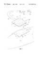
- FIG. 3is an exploded isometric view of the wound treatment apparatus
- FIG. 4is a cross-sectional view of the wound treatment apparatus applied to the wound on the person's body
- FIG. 5is a plan view of the bottom surface of a bandage in the wound treatment apparatus of FIGS. 1-4;
- FIG. 6Ais a planar illustration of an electrical resistance element embedded in a flexible layer for uniform heating
- FIG. 6Bis a view taken along plane VIB—VIB of FIG. 6A;
- FIG. 7Ais a planar view of an electrical resistance element embedded in a flexible layer for heating a portion of a treatment area
- FIG. 7Bis a view taken along plane VIIB-VIIB of FIG. 7A;
- FIG. 8Ais a planar view of an electrical resistance element embedded in a flexible layer for uniform heating of a central portion of a treatment area
- FIG. 8Bis a view taken along plane VIIIB-VIIIB of FIG. 8A;
- FIG. 9is an isometric illustration of a wound treatment apparatus with a hot water heater
- FIG. 10is an isometric illustration of a wound treatment apparatus with a chemical heater
- FIG. 11is a cross-sectional drawing of a prior art wound treatment apparatus in which heat is transferred to a bandage primarily by convection;
- FIG. 12is a cross-sectional drawing of a wound treatment apparatus according to this invention in which heat is substantially uniformly distributed throughout a bandage;
- FIG. 13is a cross-sectional drawing of the wound treatment apparatus of FIG. 12 with a polymeric film
- FIG. 14is a cross-sectional drawing of another embodiment of a wound treatment apparatus according to this invention.
- FIG. 15is a cross-sectional drawing of another embodiment of wound treatment apparatus according to this invention.
- FIG. 16is a cross-sectional drawing of the FIG. 15 embodiment of the wound treatment apparatus showing a polymeric film
- FIG. 17is a cross-sectional drawing of another embodiment of a wound treatment apparatus according to this invention.
- FIG. 18is an exploded cross-sectional view of a wound treatment apparatus showing double-sided tape employed for affixing a heater to the FIG. 13 embodiment;
- FIG. 19is an exploded cross-sectional view of a wound treatment apparatus showing double-sided tape employed for affixing a heater to the FIG. 16 embodiment;
- FIG. 20is a cross-sectional exploded view of a wound treatment apparatus showing another embodiment for affixing a heater to a bandage;
- FIG. 21is a cross-sectional exploded view of a wound treatment apparatus showing a further embodiment for affixing a heater to a bandage;
- FIG. 22is a cross-sectional exploded view of a wound treatment apparatus showing a still another embodiment for affixing a heater to a bandage.
- a wound treatment apparatus 100includes a thermally conductive bandage 102 which has first (lower) and second (upper) surfaces 104 and 106 , a heater 108 which has first (lower) and second (upper) surfaces 110 and 112 and means 114 for joining the heater 108 and the bandage 102 in such a manner as to transfer heat from the heater 108 to the bandage 102 .
- the wound treatment apparatus 100is shown in place covering a wound 116 of a person's body 118 , the wound being shown depressed.
- a periwound area 120which is typically a peripheral band of tissue around the wound area with less trauma than the tissue of the wound area.
- the wound treatment apparatusis capable of treating a wound treatment area that includes the wound and/or the periwound area, as desired.
- the second surface 106 of the bandagepreferably comprises a sheet of smooth material.
- This surfacemay be provided by a polymeric film.
- a layer 122 of hydrogel, hydrocolloid, or hydrated alginatemay be affixed to the polymeric film 106 by any suitable means, such as an adhesive, and may provide the first surface 104 . Any of these combinations provide the bandage with high thermal conductivity and maintain a moist environment at the wound.
- a foam or gauzemay be used in lieu of the compounds enumerated above. If the gauze or foam provides the first surface 104 , the gauze or foam will absorb moisture from the wound, providing the desired heat conductivity and moist environment.
- the bandage 102may simply be a single layer or film of a heat-conductive polymer so as to optimize heat conductivity of the bandage.
- the bandageis planar, as shown in FIG. 3, and flexible, so as to conform to the wound 116 as shown in FIG. 4, as well as to the person's body, as shown in FIGS. 1 and 2.
- the heater 108includes means for generating heat that may be electrically operated.
- the meansmay take hte form of an electrical resistance element 124 which is embedded in or laminated to a flexible planar member 126 , such as polyethylene, silicon, rubber or flexible cloth.
- the heater 108is substantially planar, as shown in FIGS. 1 and 3, and yet flexible in order that it conform, with the bandage, to the wound 116 , as shown in FIG. 4, and to the person's body as shown in FIGS. 2 and 4.
- the electrical resistance element 124is connected to first and second electrical conductors 128 and 130 , which are connected to an electrical power source 132 , via a controller 134 .
- the purpose of the controller 134is to control electrical power provided to the electrical resistance element 124 to maintain a normothermic environment at the wound 116 .
- the electrical resistance element 124may extend back and forth in the flexible planar member 126 with a desired spacing to promote uniform heating of the bandage 102 .
- the first surface 104 of the bandage 102is provided with a pattern of adhesive material 136 at or near its periphery.
- the adhesive pattern 136is closed so that it may encompass the wound and the periwound area and trap the natural moisture of the body which, in turn, moistens the layer 122 of the bandage, or otherwise maintains a moist environment across the wound treatment area for wound therapy purposes.
- the pattern of adhesive 136has inner and outer boundaries 138 and 140 wherein the outer boundary 140 coincides with the outer perimeter of the bandage.
- the bandage 102 , the heater 108 , and the pattern of adhesive 136may take various shapes, such as the square, shown in the drawings, or a rectangle, circle or ellipse, or any other regular or irregular shape, depending upon various shapes of wound treatment areas.
- FIGS. 6-8illustrate various electrical resistance heaters 108 .
- the heater 108 a shown in FIG. 6Aand electrical resistance element 124 a winds back and forth within the flexible planar member 126 , similar to what is shown in FIG. 1 .
- the spacing between the windings of the electrical resistance element 124 amay be sized so as to ensure substantially uniform heating.
- FIG. 6Bshows the electrical resistance element embedded or laminated in the flexible planar member 126 .
- the electrical resistance element 124 btakes a path along a peripheral zone of the flexible planar member 126 , so that the periphery of the heater 108 b is uniformly heated to a temperature greater than a central portion of the heater.
- these electrical resistance elements 124 bare shown embedded or laminated in the flexible planar member 126 in FIG. 7 B.
- the electrical resistance element 124 ctakes a spiral path out and back within a central region of the heater 108 c so as to uniformly heat the central region of the heater to a higher temperature than regions outbound therefrom.
- the heater 108 ais adapted for applying heat to both the wound and periwound area 116 and 120 in FIG. 4, the heater 108 b is adapted for applying heat primarily to the periwound area 120 and the heater 108 c is adapted for applying heat primarily to the wound 116 .
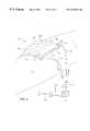
- a heater 302employs heated water as the means for generating heat to be applied to the bandage 102 and then to a wound site covered by the bandage.
- the heater 302may comprise a pouch 304 which has water channels 306 extending back and forth in series from an inlet end 308 to an outlet end 310 .
- the pouch 304may be made by thermo-setting the periphery as well as channel lines of a pair of polymeric films.
- the bottom filmmay be stiffer than the top film 312 .
- Heated wateris supplied by inlet and outlet water lines 316 and 318 which are connected to a water heater 320 via a pump 322 .
- a controller 324is provided for controlling the temperature of the water in the water heater 320 and the amount of water pumped by the pump 322 .
- the heated wateris preferably maintained at such a temperature and flow rate that the wound site 116 is maintained at a normothermic temperature.
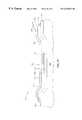
- FIG. 10Still another wound treatment apparatus 400 is illustrated in FIG. 10 .
- a heater 402employs a chemical or phase-change salt as the means for heat to be applied to the bandage 102 .
- the heater 402may comprise a pair of polymeric films which are sealed at their peripheries to provide an enclosure for the chemical or phase change salt. Further, the polymeric films may be joined by spot thermo-setting at spaced-apart locations for the purpose of lowering the profile of the heater and maintaining the chemical or phase-change salt in discrete confined areas. One film may be stiffer than the other film.
- FIG. 11is a cross-section of a wound treatment apparatus 500 that employs a bandage 502 that does not exhibit heat spreading characteristics, shown schematically for explaining its operation.
- Heatis transmitted to the bandage 502 by a heater 504 and the bandage 502 , in turn, conducts heat to the wound site 116 .
- the heater 504makes contact with an upper surface of the bandage 502 so that heat is transmitted by conduction between the heater 504 and the bandage 502 where the devices are in contact.
- the bandage 502will assume the contours of the person's body, which may include a depressed wound site. This typically causes gaps 506 between the heater 504 and the upper surface of the bandage 502 .
- the bandage 502is shown as having poor heat transfer ability at the gaps 506 which causes little heat to be received and conducted by the bandage, as shown by the small arrows. This is in contrast to a larger amount of heat conducted through the bandage, as shown by the large arrows, where the heater 504 contacts the upper surface of the bandage 502 . This results in non-uniform heat distribution at the wound site 116 , which can cause portions of the wound site to receive unsatisfactory heat therapy.
- the inventionemploys a heat spreading means acting between a heater and a thermally conductive bandage.
- the heat spreading meansreceives heat from the heater, spreads the heat latterally with respect to the lower surface of the heater and the lower surface of the bandage, and provides the heat to the bandage with a substantially uniform distribution across the bandage.
- the heat spreading meansmay be in the structure of the bandage itself and thus may be part of the bandage.
- the heat spreading meansmay also be an element that is physically separate from the bandage.
- FIG. 12shows a cross-section of a wound treatment apparatus 510 which employs a bandage 512 , with arrows showing the heat received and conducted therethrough.
- the bandage 512has an upper surface 513 and a lower surface 515 .
- the heater 514makes contact with the upper surface 513 of the bandage 512 with the exception of gaps 516 between the heater and the upper surface of the bandage 512 due to contour of the wound site 116 .
- the bandage 512is made of a thermally conductive material that is thick enough to permit heat at spaced apart contact regions 518 and 520 , adjacent a non-contact region 522 at the upper surface of the bandage, to flow by conduction from the upper surface 513 and to substantially merge at 526 at the lower surface 515 of the bandage 512 .
- the lack of heat conduction at the gaps 516can be overcome by lateral conduction of the heat within the bandage 512 due to the conductive material and the thickness of the bandage 512 . This results in a substantially uniform distribution of heat across the lower surface 515 .
- a wound treatment apparatus 530 shown in FIG. 13includes an embodiment 532 of the thermally conductive bandage of FIG. 12 .
- the bandage 532includes an upper surface 533 and a lower surface 535 .
- the bandage 532 and a heater 534are shown depressed within the wound site 116 causing gaps 538 between the heater 534 and the bandage 532 .
- the bandage 532is fabricated from thermally conductive material sufficiently thick that heat introduced at the upper surface 533 may spread laterally in the bandage 532 and may be provided at the lower surface 535 with a substantially uniform distribution across that surface, as the embodiment shown in FIG. 12 .
- the material of which the bandage 532 is madeincludes a thermally-conductive fluid, such as a hydrated material.
- the top surface of the bandage 532comprise a polymeric film 544 .
- the polymeric film 544serves a double function: retention of fluid or water within the bandage 532 , and provision of a surface for attaching the heater 534 to the top surface of the bandage 532 with an adhesive.
- the heater 534may be electrically operated and may receive its power from a power supply and controller via leads 546 for maintaining a normothermic temperature at a wound treatment area.
- the heater 534also comprise other means of generating heat.
- the bandage 532essentially forms a heat spreading layer.
- FIG. 14is a cross-section of a wound treatment apparatus 550 which employs a second embodiment 552 of a thermally conductive bandage.
- the bandagehas an upper surface 553 and a lower surface 555 .
- the wound treatment apparatus 550is depressed in the wound 116 , which causes gaps 556 between the heater 558 and the bandage 552 .
- the bandage 552is a flexible pouch 560 which is filled with a thermally conductive fluid such as water 562 .
- the pouchmay be made from polymeric films which are sealed around a periphery 564 .
- the depth of the fluid in the pouchis such that heat that is conducted from the upper surface 553 to the lower surface 555 spreads laterally throughout the bandage 552 so that it is substantially uniformly distributed across the lower surface 555 .
- the bandage 552in essence forms a heat spreading layer.
- FIG. 15shows a cross-section of a wound treatment apparatus 570 that employs a separate heat spreading layer 572 sandwiched between a bandage 574 and a heater 576 , the heat spreading layer 572 being shown schematically with arrows for explaining the heat within the heat spreading layer.
- the heat spreading layer 572includes an upper surface 572 u and a lower surface 572 l.
- the bandage 574includes an upper surface 573 and a lower surface 575 .
- the wound treatment apparatus 570is shown depressed in a wound 116 , with gaps 580 formed between the heater 576 and the heat spreading layer 572 .
- the heat spreading layer 572is made of a material with high thermal conductivity, while the bandage 574 is made of a material with low thermal conductivity, such as gauze.
- the heat spreading layer 572is employed for laterally spreading the heat adjacent the gaps 580 from the upper surface 572 u to the lower surface 572 l of the heat spreading layer 572 so that the heat is substantially uniformly distributed across the upper surface 573 of the bandage 574 , as shown by the large arrows. Because of the nature of the material of which the bandage 574 is made, the heat remains substantially uniformly distributed through the bandage 574 and across the lower surface 575 .
- the wound treatment apparatus 570is shown without the arrows.
- a fluid containing materialsuch as a hydrated material may be employed for the heat spreading layer 572 .
- Suitable materialsare hydrogels and hydrocolloids.
- the heat spreading layer 572may optionally be provided with a thin polymeric film 582 applied to the upper surface 572 u for retaining fluid within the heat spreading layer, as well as for providing adhesion between the heater 576 and the heat spreading layer 572 .
- the heat spreading layer 572 and the bandage 574be made as one component, with the heat spreading layer 572 and the bandage 574 having a common layer 584 therebetween. This will ensure that there are no gaps between the heat spreading layer 572 and the bandage 574 .
- the heater 576may be electrically actuated, or may comprise a non-electric means for generating heat.
- FIG. 17shows a cross-section of a wound treatment apparatus 590 which employs a separate heat spreading layer 592 between a bandage 594 and a heater 596 .
- the heat spreading layer 592is a pouch 598 which contains a heat conductive fluid such as water 600 .
- the pouchis formed on the upper surface 593 of the bandage 594 .
- the pouch 598may comprise polymeric films which are sealed at a periphery 602 . Because of the depression of the wound 116 , there are gaps 610 between the heater 596 and the heat spreading layer 592 .
- the depth or thickness of the fluid or water 600 in the pouch 598is sufficient to spread heat laterally so that the heat is uniformly distributed across the bandage 594 and across its lower surface 595 .
- FIG. 18is an exploded illustration of the wound treatment apparatus 530 shown in FIG. 13 .
- the bandage 532 and the heater 534are highly flexible; in the figure, they are planar and in a non-flexed condition.
- the lower surface 535 of the bandage 532is provided with a pattern of adhesive material at 612 around its periphery for adhering the bandage 532 to the person's body 118 . When attached to the person's body, the pattern of adhesive material retains moisture at the wound treatment area.
- the heater 534may be attached to the polymeric film 544 of the bandage by double-sided tape 614 .
- the pull strength of the double-sided tape 614may be less than the pull strength of the pattern of adhesive material 612 so that the heater 534 can be removed without removing the bandage 532 from the person's body.
- FIG. 19is an exploded illustration of the wound treatment apparatus 570 in FIG. 16 .
- the bottom surface 575 of the bandage 574is provided with a pattern of adhesive 614 around its periphery for attaching the bandage 574 to the person's body.
- the pattern of adhesive materialretains moisture at the wound treatment area, when the bandage is attached.
- the heater 576is attached to the heat spreading layer 572 by a double-sided tape 616 as described hereinabove. Again, the pull strength of the double-sided tape 616 may be less than the pull strength of the pattern of adhesive material 614 so that the heater 576 can be removed from the heat spreading layer 572 without removing the bandage 574 from the person's body.
- FIG. 20shows an exploded illustration of a wound treatment apparatus 620 which employs a modified attachment device for attaching the heater 622 to a thermally conductive flexible bandage 624 .
- the bandage 624is the same as the bandage 532 in FIG. 13 except the polymeric film 544 is replaced by hook-and-eye material 626 .
- the bottom surface 621 of the heater 622is also provided with hook-and-eye material 628 so that the heater 622 can be easily attached to the bandage 624 .
- the hook-and-eye materialwill inherently have minute gaps and may have additional larger gaps because of the depression of the wound 116 .
- the bandage 624is provided with a thermally conductive material that is thick enough to spread heat laterally within the bandage 624 so as to distribute heat uniformly from its upper surface 623 to its lower surface 625 as shown in FIG. 12 .
- the lower surface 625 of the bandage 624may have a pattern of adhesive material 630 with greater pull strength than the hook-and-eye material 626 / 628 .
- the pattern of adhesive material 630retains moisture at the wound treatment area.
- FIG. 21shows an exploded illustration of a wound treatment apparatus 640 which employs another device for attaching a heater 642 to a bandage 644 .
- the bandage 644is the same as the bandage 532 in FIG. 13 except the polymeric film 544 may be omitted.
- adhesive tabs 646which extend from the upper surface 642 u of the heater 642 , are employed for attaching the bandage 644 to the person's body 118 .
- the heater 642can then be removed by pulling the tabs 646 from the person's body. If a pattern of adhesive material 648 is employed about the bottom periphery of the bandage 644 , the bandage 644 will remain in place when the heater 642 is removed.
- the entire heat treatment apparatus 640can be removed upon pulling the tabs 646 from the person's body.
- the tabs 646may be adhesively attached to the bandage 644 .
- the polymeric film 544 in FIG. 13 and the body adhesive 648should be employed.
- FIG. 22shows an exploded cross-section of a heat treatment apparatus 650 which employs a still another attachment device for attaching a heater 652 to a bandage 654 .
- the straps 656extend completely around the person's body, such as around a leg or arm, in order to hold the heater 652 against the upper surface 653 of the bandage 654 .
- the bandage 654it is not necessary for the bandage 654 to have a polymeric film on its upper surface.
- the bandage 654will remain attached to the body upon releasing the straps whereas if the body adhesive material 658 is omitted the entire wound treatment apparatus 650 will be removed upon release of the straps.
Landscapes
- Health & Medical Sciences (AREA)
- Vascular Medicine (AREA)
- Thermal Sciences (AREA)
- Engineering & Computer Science (AREA)
- Biomedical Technology (AREA)
- Heart & Thoracic Surgery (AREA)
- Physics & Mathematics (AREA)
- Life Sciences & Earth Sciences (AREA)
- Animal Behavior & Ethology (AREA)
- General Health & Medical Sciences (AREA)
- Public Health (AREA)
- Veterinary Medicine (AREA)
- Thermotherapy And Cooling Therapy Devices (AREA)
Abstract
Description
Claims (16)
Priority Applications (2)
| Application Number | Priority Date | Filing Date | Title |
|---|---|---|---|
| US09/056,191US6235047B1 (en) | 1998-04-06 | 1998-04-06 | Wound treatment apparatus with a heater, a heat conductive bandage, and heat-spreading means acting between the heater and bandage |
| US09/771,790US6641601B1 (en) | 1998-04-06 | 2001-01-29 | Tissue treatment apparatus with a heater, a heat conductive bandage, and a heat-spreading means acting between the heater and bandage |
Applications Claiming Priority (1)
| Application Number | Priority Date | Filing Date | Title |
|---|---|---|---|
| US09/056,191US6235047B1 (en) | 1998-04-06 | 1998-04-06 | Wound treatment apparatus with a heater, a heat conductive bandage, and heat-spreading means acting between the heater and bandage |
Related Child Applications (1)
| Application Number | Title | Priority Date | Filing Date |
|---|---|---|---|
| US09/771,790ContinuationUS6641601B1 (en) | 1998-04-06 | 2001-01-29 | Tissue treatment apparatus with a heater, a heat conductive bandage, and a heat-spreading means acting between the heater and bandage |
Publications (1)
| Publication Number | Publication Date |
|---|---|
| US6235047B1true US6235047B1 (en) | 2001-05-22 |
Family
ID=22002784
Family Applications (2)
| Application Number | Title | Priority Date | Filing Date |
|---|---|---|---|
| US09/056,191Expired - LifetimeUS6235047B1 (en) | 1998-04-06 | 1998-04-06 | Wound treatment apparatus with a heater, a heat conductive bandage, and heat-spreading means acting between the heater and bandage |
| US09/771,790Expired - LifetimeUS6641601B1 (en) | 1998-04-06 | 2001-01-29 | Tissue treatment apparatus with a heater, a heat conductive bandage, and a heat-spreading means acting between the heater and bandage |
Family Applications After (1)
| Application Number | Title | Priority Date | Filing Date |
|---|---|---|---|
| US09/771,790Expired - LifetimeUS6641601B1 (en) | 1998-04-06 | 2001-01-29 | Tissue treatment apparatus with a heater, a heat conductive bandage, and a heat-spreading means acting between the heater and bandage |
Country Status (1)
| Country | Link |
|---|---|
| US (2) | US6235047B1 (en) |
Cited By (45)
| Publication number | Priority date | Publication date | Assignee | Title |
|---|---|---|---|---|
| US20030014022A1 (en)* | 2001-07-12 | 2003-01-16 | Lockwood Jeffrey S. | Control of vacuum level rate of change |
| US6585670B2 (en) | 1998-04-06 | 2003-07-01 | Augustine Medical, Inc. | Treatment apparatus with a heater adhesively joined to a bandage |
| US6613953B1 (en)* | 2002-03-22 | 2003-09-02 | Dan Altura | Insulator-conductor device for maintaining a wound near normal body temperature |
| US6641601B1 (en)* | 1998-04-06 | 2003-11-04 | Augustine Medical, Inc. | Tissue treatment apparatus with a heater, a heat conductive bandage, and a heat-spreading means acting between the heater and bandage |
| US6685681B2 (en) | 2000-11-29 | 2004-02-03 | Hill-Rom Services, Inc. | Vacuum therapy and cleansing dressing for wounds |
| US6800074B2 (en) | 1999-11-29 | 2004-10-05 | Hill-Rom Services, Inc. | Wound treatment apparatus |
| US20040243073A1 (en)* | 2001-12-26 | 2004-12-02 | Lockwood Jeffrey S. | Wound vacuum therapy dressing kit |
| US20050004534A1 (en)* | 2001-12-26 | 2005-01-06 | Lockwood Jeffery S | Vented vacuum bandage and method |
| US20050085795A1 (en)* | 2002-02-28 | 2005-04-21 | Lockwood Jeffrey S. | External catheter access to vacuum bandage |
| US20060189912A1 (en)* | 2003-02-07 | 2006-08-24 | Luca Garabet | Multi-layer combination of an electric stimulation electrode and a wound dressing |
| US20060235347A1 (en)* | 2005-04-16 | 2006-10-19 | Adel Aali | Deformable and conformable wound protecting apparatus and its method of application |
| US20070027481A1 (en)* | 2005-07-28 | 2007-02-01 | Weinfield Todd A | Apparatus and Method for Treatment of Infected Nail |
| WO2007058533A1 (en)* | 2005-11-16 | 2007-05-24 | Joyincare Group B.V. | Device for heating cloths and method for applying such a device |
| US20070142761A1 (en)* | 2005-12-15 | 2007-06-21 | Adel Aali | Wound shield |
| US20070142757A1 (en)* | 2005-12-15 | 2007-06-21 | Adel Aali | Wound shield and warming apparatus and method |
| US20070161938A1 (en)* | 2006-01-12 | 2007-07-12 | Adel Aali | Dressing substrate |
| US20070191754A1 (en)* | 2006-02-13 | 2007-08-16 | Adel Aali | Wound shield |
| US7276051B1 (en) | 1998-08-07 | 2007-10-02 | Hill-Rom Services, Inc. | Wound treatment apparatus |
| US20080103550A1 (en)* | 2006-10-30 | 2008-05-01 | Stuart Wenzel | Multiple electrode wound healing patch |
| US20080103549A1 (en)* | 2006-10-30 | 2008-05-01 | Stuart Wenzel | Wound healing patch with guard electrodes |
| US7534927B2 (en) | 2001-12-26 | 2009-05-19 | Hill-Rom Services, Inc. | Vacuum bandage packing |
| US7678090B2 (en) | 1999-11-29 | 2010-03-16 | Risk Jr James R | Wound treatment apparatus |
| US7763000B2 (en) | 1999-11-29 | 2010-07-27 | Risk Jr James R | Wound treatment apparatus having a display |
| US20100312159A1 (en)* | 2005-04-16 | 2010-12-09 | Adel Aali | Secondary Wound Dressings for Securing Primary Dressings and Managing Fluid from Wounds, and Methods of Using Same |
| US20110015557A1 (en)* | 2009-07-16 | 2011-01-20 | Aalnex, Inc. | Systems And Methods For Protecting Incisions |
| US7896856B2 (en) | 2002-08-21 | 2011-03-01 | Robert Petrosenko | Wound packing for preventing wound closure |
| US7910791B2 (en) | 2000-05-22 | 2011-03-22 | Coffey Arthur C | Combination SIS and vacuum bandage and method |
| US7927318B2 (en) | 2001-10-11 | 2011-04-19 | Risk Jr James Robert | Waste container for negative pressure therapy |
| US7928281B2 (en) | 1992-06-19 | 2011-04-19 | Arizant Technologies Llc | Wound covering |
| US7931651B2 (en) | 2006-11-17 | 2011-04-26 | Wake Lake University Health Sciences | External fixation assembly and method of use |
| US20110172750A1 (en)* | 2010-01-11 | 2011-07-14 | David Ellsworth Cassidy | Methods and apparatus for active patient warming |
| US7988680B2 (en) | 2000-11-29 | 2011-08-02 | Kci Medical Resources | Vacuum therapy and cleansing dressing for wounds |
| US8067662B2 (en) | 2009-04-01 | 2011-11-29 | Aalnex, Inc. | Systems and methods for wound protection and exudate management |
| US8168848B2 (en) | 2002-04-10 | 2012-05-01 | KCI Medical Resources, Inc. | Access openings in vacuum bandage |
| US8267960B2 (en) | 2008-01-09 | 2012-09-18 | Wake Forest University Health Sciences | Device and method for treating central nervous system pathology |
| US8377016B2 (en) | 2007-01-10 | 2013-02-19 | Wake Forest University Health Sciences | Apparatus and method for wound treatment employing periodic sub-atmospheric pressure |
| US8834520B2 (en) | 2007-10-10 | 2014-09-16 | Wake Forest University | Devices and methods for treating spinal cord tissue |
| US9289193B2 (en) | 2008-07-18 | 2016-03-22 | Wake Forest University Health Sciences | Apparatus and method for cardiac tissue modulation by topical application of vacuum to minimize cell death and damage |
| US20170354542A1 (en)* | 1999-04-02 | 2017-12-14 | Kci Licensing, Inc. | Negative Pressure Treatment System With Heating And Cooling Provision |
| WO2019109088A1 (en)* | 2017-12-01 | 2019-06-06 | Jabil Inc. | Apparatus, system and method of providing a conformable heater system |
| US10583228B2 (en) | 2015-07-28 | 2020-03-10 | J&M Shuler Medical, Inc. | Sub-atmospheric wound therapy systems and methods |
| US11160917B2 (en) | 2020-01-22 | 2021-11-02 | J&M Shuler Medical Inc. | Negative pressure wound therapy barrier |
| WO2024064343A1 (en)* | 2022-09-23 | 2024-03-28 | Board Of Regents, The University Of Texas System | Devices and methods for safely and effectively raising or maintaining core body temperature |
| US12076543B2 (en) | 2017-08-22 | 2024-09-03 | Jabil Inc. | Apparatus, system and method of providing a conformable heater system |
| US12376193B2 (en) | 2017-08-29 | 2025-07-29 | Jabil Inc. | Apparatus, system and method of providing a conformable heater in wearables |
Families Citing this family (16)
| Publication number | Priority date | Publication date | Assignee | Title |
|---|---|---|---|---|
| US7147653B2 (en)* | 2002-08-23 | 2006-12-12 | Lumitex, Inc. | Pad like device for use during phototherapy treatment |
| US7896910B2 (en) | 2004-05-17 | 2011-03-01 | Coolsystems, Inc. | Modular apparatus for therapy of an animate body |
| US7686839B2 (en)* | 2005-01-26 | 2010-03-30 | Lumitex, Inc. | Phototherapy treatment devices for applying area lighting to a wound |
| US7751980B2 (en)* | 2006-12-22 | 2010-07-06 | Schlumberger Technology Corporation | Method and apparatus for evaluating elastic mechanical properties of a transversely isotropic formation |
| US7837638B2 (en) | 2007-02-13 | 2010-11-23 | Coolsystems, Inc. | Flexible joint wrap |
| US20100021530A1 (en)* | 2008-07-25 | 2010-01-28 | Innovation Biomedical Devices, Inc. | Enhanced trans-keratin drug delivery |
| US20100145421A1 (en)* | 2008-12-05 | 2010-06-10 | Coolsystems, Inc. | Therapeutic Cooling and/or Heating System Including A Thermo-Conductive Material |
| EP3714848A1 (en)* | 2009-10-22 | 2020-09-30 | Coolsystems, Inc. | Temperature and flow control methods in a thermal therapy device |
| US8597217B2 (en) | 2010-12-30 | 2013-12-03 | Coolsystems, Inc. | Reinforced therapeutic wrap and method |
| US9615967B2 (en) | 2010-12-30 | 2017-04-11 | Coolsystems, Inc. | Reinforced therapeutic wrap and method |
| US10010446B2 (en) | 2011-01-05 | 2018-07-03 | Hill-Rom Services, Inc. | Cooling system for an occupant of an occupant support and a cooling garment |
| US10463565B2 (en) | 2011-06-17 | 2019-11-05 | Coolsystems, Inc. | Adjustable patient therapy device |
| US10456320B2 (en) | 2013-10-01 | 2019-10-29 | Coolsystems, Inc. | Hand and foot wraps |
| US20160038336A1 (en) | 2014-08-05 | 2016-02-11 | Tamara L. HILTON | Integrated multisectional heat exchanger |
| WO2016061619A1 (en) | 2014-10-21 | 2016-04-28 | Hexima Limited | A method of treatment |
| US10859295B2 (en) | 2016-04-13 | 2020-12-08 | ZeoThermal Technologies, LLC | Cooling and heating platform |
Citations (4)
| Publication number | Priority date | Publication date | Assignee | Title |
|---|---|---|---|---|
| US3867939A (en)* | 1972-05-18 | 1975-02-25 | Moore Perk Corp | Disposable, sterile temperature control applicator pad for medical application |
| WO1994000090A2 (en)* | 1992-06-19 | 1994-01-06 | Augustine Scott D | Wound covering |
| US5662624A (en)* | 1992-03-27 | 1997-09-02 | Coloplast A/S | Heat dressing comprising a heat generating unit and an adhesive layer |
| US5817145A (en)* | 1994-11-21 | 1998-10-06 | Augustine Medical, Inc. | Wound treatment device |
Family Cites Families (3)
| Publication number | Priority date | Publication date | Assignee | Title |
|---|---|---|---|---|
| DE69314313T2 (en)* | 1992-08-10 | 1998-04-23 | Okanagan House Inc | THERMAL BANDAGE |
| US6134475A (en) | 1997-01-22 | 2000-10-17 | Will; Frank J. | Therapeutic device |
| US6235047B1 (en)* | 1998-04-06 | 2001-05-22 | Augustine Medical, Inc. | Wound treatment apparatus with a heater, a heat conductive bandage, and heat-spreading means acting between the heater and bandage |
- 1998
- 1998-04-06USUS09/056,191patent/US6235047B1/ennot_activeExpired - Lifetime
- 2001
- 2001-01-29USUS09/771,790patent/US6641601B1/ennot_activeExpired - Lifetime
Patent Citations (4)
| Publication number | Priority date | Publication date | Assignee | Title |
|---|---|---|---|---|
| US3867939A (en)* | 1972-05-18 | 1975-02-25 | Moore Perk Corp | Disposable, sterile temperature control applicator pad for medical application |
| US5662624A (en)* | 1992-03-27 | 1997-09-02 | Coloplast A/S | Heat dressing comprising a heat generating unit and an adhesive layer |
| WO1994000090A2 (en)* | 1992-06-19 | 1994-01-06 | Augustine Scott D | Wound covering |
| US5817145A (en)* | 1994-11-21 | 1998-10-06 | Augustine Medical, Inc. | Wound treatment device |
Cited By (86)
| Publication number | Priority date | Publication date | Assignee | Title |
|---|---|---|---|---|
| US7928281B2 (en) | 1992-06-19 | 2011-04-19 | Arizant Technologies Llc | Wound covering |
| US6585670B2 (en) | 1998-04-06 | 2003-07-01 | Augustine Medical, Inc. | Treatment apparatus with a heater adhesively joined to a bandage |
| US6641601B1 (en)* | 1998-04-06 | 2003-11-04 | Augustine Medical, Inc. | Tissue treatment apparatus with a heater, a heat conductive bandage, and a heat-spreading means acting between the heater and bandage |
| US20070233022A1 (en)* | 1998-08-07 | 2007-10-04 | Hill-Rom Services, Inc. | Wound treatment apparatus |
| US7794438B2 (en) | 1998-08-07 | 2010-09-14 | Alan Wayne Henley | Wound treatment apparatus |
| US8540687B2 (en) | 1998-08-07 | 2013-09-24 | Kci Licensing, Inc. | Wound treatment apparatus |
| US7276051B1 (en) | 1998-08-07 | 2007-10-02 | Hill-Rom Services, Inc. | Wound treatment apparatus |
| US20170354542A1 (en)* | 1999-04-02 | 2017-12-14 | Kci Licensing, Inc. | Negative Pressure Treatment System With Heating And Cooling Provision |
| US10736787B2 (en)* | 1999-04-02 | 2020-08-11 | Kci Licensing, Inc. | Negative pressure treatment system with heating and cooling provision |
| US6800074B2 (en) | 1999-11-29 | 2004-10-05 | Hill-Rom Services, Inc. | Wound treatment apparatus |
| US8021348B2 (en) | 1999-11-29 | 2011-09-20 | Kci Medical Resources | Wound treatment apparatus |
| US7678090B2 (en) | 1999-11-29 | 2010-03-16 | Risk Jr James R | Wound treatment apparatus |
| US7763000B2 (en) | 1999-11-29 | 2010-07-27 | Risk Jr James R | Wound treatment apparatus having a display |
| US8747887B2 (en) | 2000-05-22 | 2014-06-10 | Kci Medical Resources | Combination SIS and vacuum bandage and method |
| US7910791B2 (en) | 2000-05-22 | 2011-03-22 | Coffey Arthur C | Combination SIS and vacuum bandage and method |
| US7988680B2 (en) | 2000-11-29 | 2011-08-02 | Kci Medical Resources | Vacuum therapy and cleansing dressing for wounds |
| US7867206B2 (en) | 2000-11-29 | 2011-01-11 | Kci Licensing, Inc. | Vacuum therapy and cleansing dressing for wounds |
| US6685681B2 (en) | 2000-11-29 | 2004-02-03 | Hill-Rom Services, Inc. | Vacuum therapy and cleansing dressing for wounds |
| US8246592B2 (en) | 2000-11-29 | 2012-08-21 | Kci Medical Resources | Vacuum therapy and cleansing dressing for wounds |
| US6752794B2 (en) | 2000-11-29 | 2004-06-22 | Hill-Rom Services, Inc. | Vacuum therapy and cleansing dressing for wounds |
| US10357404B2 (en) | 2000-11-29 | 2019-07-23 | Kci Medical Resources Unlimited Company | Vacuum therapy and cleansing dressing for wounds |
| US7022113B2 (en) | 2001-07-12 | 2006-04-04 | Hill-Rom Services, Inc. | Control of vacuum level rate of change |
| US20030014022A1 (en)* | 2001-07-12 | 2003-01-16 | Lockwood Jeffrey S. | Control of vacuum level rate of change |
| US7927318B2 (en) | 2001-10-11 | 2011-04-19 | Risk Jr James Robert | Waste container for negative pressure therapy |
| US7195624B2 (en) | 2001-12-26 | 2007-03-27 | Hill-Rom Services, Inc. | Vented vacuum bandage with irrigation for wound healing and method |
| US7534927B2 (en) | 2001-12-26 | 2009-05-19 | Hill-Rom Services, Inc. | Vacuum bandage packing |
| US20050004534A1 (en)* | 2001-12-26 | 2005-01-06 | Lockwood Jeffery S | Vented vacuum bandage and method |
| US20040243073A1 (en)* | 2001-12-26 | 2004-12-02 | Lockwood Jeffrey S. | Wound vacuum therapy dressing kit |
| US7723560B2 (en) | 2001-12-26 | 2010-05-25 | Lockwood Jeffrey S | Wound vacuum therapy dressing kit |
| US7896864B2 (en) | 2001-12-26 | 2011-03-01 | Lockwood Jeffrey S | Vented vacuum bandage with irrigation for wound healing and method |
| US8350116B2 (en) | 2001-12-26 | 2013-01-08 | Kci Medical Resources | Vacuum bandage packing |
| US20050085795A1 (en)* | 2002-02-28 | 2005-04-21 | Lockwood Jeffrey S. | External catheter access to vacuum bandage |
| US7338482B2 (en) | 2002-02-28 | 2008-03-04 | Hill-Rom Services, Inc. | External catheter access to vacuum bandage |
| US6613953B1 (en)* | 2002-03-22 | 2003-09-02 | Dan Altura | Insulator-conductor device for maintaining a wound near normal body temperature |
| US8168848B2 (en) | 2002-04-10 | 2012-05-01 | KCI Medical Resources, Inc. | Access openings in vacuum bandage |
| US7896856B2 (en) | 2002-08-21 | 2011-03-01 | Robert Petrosenko | Wound packing for preventing wound closure |
| US7689285B2 (en)* | 2003-02-07 | 2010-03-30 | Gerromed Pflege Und Medizintechnik Gmbh & Co. Kg | Multi-layer combination of an electric stimulation electrode and a wound dressing |
| US20060189912A1 (en)* | 2003-02-07 | 2006-08-24 | Luca Garabet | Multi-layer combination of an electric stimulation electrode and a wound dressing |
| US7745683B2 (en) | 2005-04-16 | 2010-06-29 | Aalnex, Inc. | Deformable and conformable wound protecting apparatus and its method of application |
| US8415523B2 (en) | 2005-04-16 | 2013-04-09 | Aalnex, Inc. | Secondary wound dressings for securing primary dressings and managing fluid from wounds, and methods of using same |
| US20100312159A1 (en)* | 2005-04-16 | 2010-12-09 | Adel Aali | Secondary Wound Dressings for Securing Primary Dressings and Managing Fluid from Wounds, and Methods of Using Same |
| US20060235347A1 (en)* | 2005-04-16 | 2006-10-19 | Adel Aali | Deformable and conformable wound protecting apparatus and its method of application |
| US7793666B2 (en) | 2005-07-28 | 2010-09-14 | Innovation Biomedical Devices, Inc. | Apparatus and method for treatment of infected nail |
| US20070027481A1 (en)* | 2005-07-28 | 2007-02-01 | Weinfield Todd A | Apparatus and Method for Treatment of Infected Nail |
| WO2007058533A1 (en)* | 2005-11-16 | 2007-05-24 | Joyincare Group B.V. | Device for heating cloths and method for applying such a device |
| US20100004611A1 (en)* | 2005-12-15 | 2010-01-07 | Adel Aali | Wound Shield With Enclosed Vacuum Space |
| US7601129B2 (en) | 2005-12-15 | 2009-10-13 | Aalnex, Inc. | Wound shield and warming apparatus and method |
| US20070142761A1 (en)* | 2005-12-15 | 2007-06-21 | Adel Aali | Wound shield |
| US8362315B2 (en) | 2005-12-15 | 2013-01-29 | Aalnex, Inc. | Dressing substrate |
| US20070142757A1 (en)* | 2005-12-15 | 2007-06-21 | Adel Aali | Wound shield and warming apparatus and method |
| US8586818B2 (en) | 2005-12-15 | 2013-11-19 | Aalnex, Inc. | Wound shield |
| US8558050B2 (en) | 2005-12-15 | 2013-10-15 | Aalnex, Inc. | Wound shield with enclosed vacuum space |
| US20070161938A1 (en)* | 2006-01-12 | 2007-07-12 | Adel Aali | Dressing substrate |
| US7863495B2 (en) | 2006-01-12 | 2011-01-04 | Aalnex, Inc. | Dressing substrate |
| US8227657B2 (en) | 2006-02-13 | 2012-07-24 | Aalnex, Inc. | Wound shield |
| US20070191754A1 (en)* | 2006-02-13 | 2007-08-16 | Adel Aali | Wound shield |
| US8669408B2 (en) | 2006-02-13 | 2014-03-11 | Aalnex, Inc. | Wound shield |
| US20110034888A1 (en)* | 2006-02-13 | 2011-02-10 | Aalnex, Inc. | Wound shield |
| US7816577B2 (en) | 2006-02-13 | 2010-10-19 | Aalnex, Inc. | Wound shield |
| US20080103550A1 (en)* | 2006-10-30 | 2008-05-01 | Stuart Wenzel | Multiple electrode wound healing patch |
| US20080103549A1 (en)* | 2006-10-30 | 2008-05-01 | Stuart Wenzel | Wound healing patch with guard electrodes |
| US7756586B2 (en) | 2006-10-30 | 2010-07-13 | Lifescan, Inc. | Wound healing patch with guard electrodes |
| US8454603B2 (en) | 2006-11-17 | 2013-06-04 | Wake Forest University Health Sciences | External fixation assembly and method of use |
| US9050136B2 (en) | 2006-11-17 | 2015-06-09 | Wake Forest University Health Sciences | External fixation assembly and method of use |
| US7931651B2 (en) | 2006-11-17 | 2011-04-26 | Wake Lake University Health Sciences | External fixation assembly and method of use |
| US8377016B2 (en) | 2007-01-10 | 2013-02-19 | Wake Forest University Health Sciences | Apparatus and method for wound treatment employing periodic sub-atmospheric pressure |
| US9737455B2 (en) | 2007-01-10 | 2017-08-22 | Wake Forest Univeristy Health Sciences | Apparatus and method for wound treatment employing periodic sub-atmospheric pressure |
| US8834520B2 (en) | 2007-10-10 | 2014-09-16 | Wake Forest University | Devices and methods for treating spinal cord tissue |
| US8267960B2 (en) | 2008-01-09 | 2012-09-18 | Wake Forest University Health Sciences | Device and method for treating central nervous system pathology |
| US8764794B2 (en) | 2008-01-09 | 2014-07-01 | Wake Forest University Health Sciences | Device and method for treating central nervous system pathology |
| US10076318B2 (en) | 2008-07-18 | 2018-09-18 | Wake Forest University Health Sciences | Apparatus and method for cardiac tissue modulation by topical application of vacuum to minimize cell death and damage |
| US9289193B2 (en) | 2008-07-18 | 2016-03-22 | Wake Forest University Health Sciences | Apparatus and method for cardiac tissue modulation by topical application of vacuum to minimize cell death and damage |
| US8722960B2 (en) | 2009-04-01 | 2014-05-13 | Aalnex, Inc. | Systems and methods for wound protection and exudate management |
| US8067662B2 (en) | 2009-04-01 | 2011-11-29 | Aalnex, Inc. | Systems and methods for wound protection and exudate management |
| US20110015557A1 (en)* | 2009-07-16 | 2011-01-20 | Aalnex, Inc. | Systems And Methods For Protecting Incisions |
| US8252971B2 (en) | 2009-07-16 | 2012-08-28 | Aalnex, Inc. | Systems and methods for protecting incisions |
| US20110172750A1 (en)* | 2010-01-11 | 2011-07-14 | David Ellsworth Cassidy | Methods and apparatus for active patient warming |
| US10583228B2 (en) | 2015-07-28 | 2020-03-10 | J&M Shuler Medical, Inc. | Sub-atmospheric wound therapy systems and methods |
| US12364625B2 (en) | 2015-07-28 | 2025-07-22 | J&M Shuler Medical, Inc. | Sub-atmospheric wound therapy systems and methods |
| US12076543B2 (en) | 2017-08-22 | 2024-09-03 | Jabil Inc. | Apparatus, system and method of providing a conformable heater system |
| US12376193B2 (en) | 2017-08-29 | 2025-07-29 | Jabil Inc. | Apparatus, system and method of providing a conformable heater in wearables |
| WO2019109088A1 (en)* | 2017-12-01 | 2019-06-06 | Jabil Inc. | Apparatus, system and method of providing a conformable heater system |
| US11160917B2 (en) | 2020-01-22 | 2021-11-02 | J&M Shuler Medical Inc. | Negative pressure wound therapy barrier |
| US11766514B2 (en) | 2020-01-22 | 2023-09-26 | J&M Shuler Medical Inc. | Negative pressure wound therapy barrier |
| US12168090B2 (en) | 2020-01-22 | 2024-12-17 | J&M Shuler Medical Inc. | Barrier to prevent or reduce ingrowth of tissue |
| WO2024064343A1 (en)* | 2022-09-23 | 2024-03-28 | Board Of Regents, The University Of Texas System | Devices and methods for safely and effectively raising or maintaining core body temperature |
Also Published As
| Publication number | Publication date |
|---|---|
| US6641601B1 (en) | 2003-11-04 |
Similar Documents
| Publication | Publication Date | Title |
|---|---|---|
| US6235047B1 (en) | Wound treatment apparatus with a heater, a heat conductive bandage, and heat-spreading means acting between the heater and bandage | |
| US6436063B1 (en) | Wound treatment apparatus with a heater adhesively joined to bandage | |
| US6080189A (en) | Wound treatment apparatus including a heater and an IR-Transparent or IR-Transmissive bandage | |
| US6213965B1 (en) | Wound treatment apparatus with infrared absorptive wound cover | |
| US6589270B2 (en) | Normothermic treatment apparatus with chemical, phase-change, or hot water means for heating | |
| US6569189B1 (en) | Tissue treatment apparatus including a bandpass filter transparent to selected wavelengths of IR electromagnetic spectrum | |
| US6264622B1 (en) | Normothermic heater wound covering | |
| US6423018B1 (en) | Normothermic tissue heating wound covering | |
| US6407307B1 (en) | Near hyperthermic heater covering | |
| US6840915B2 (en) | Normothermic tissue treatment |
Legal Events
| Date | Code | Title | Description |
|---|---|---|---|
| AS | Assignment | Owner name:AUGUSTINE MEDICAL, INC., MINNESOTA Free format text:ASSIGNMENT OF ASSIGNORS INTEREST;ASSIGNORS:AUGUSTINE, SCOTT D.;LELAND, KEITH J.;ROCK, JOHN P.;AND OTHERS;REEL/FRAME:009582/0030 Effective date:19980403 | |
| STCF | Information on status: patent grant | Free format text:PATENTED CASE | |
| AS | Assignment | Owner name:ARIZANT TECHNOLOGIES LLC, MINNESOTA Free format text:ASSIGNMENT OF ASSIGNORS INTEREST;ASSIGNOR:AUGUSTINE MEDICAL, INC.;REEL/FRAME:015711/0304 Effective date:20040506 Owner name:ARIZANT TECHNOLOGIES LLC,MINNESOTA Free format text:ASSIGNMENT OF ASSIGNORS INTEREST;ASSIGNOR:AUGUSTINE MEDICAL, INC.;REEL/FRAME:015711/0304 Effective date:20040506 | |
| AS | Assignment | Owner name:MERRILL LYNCH CAPITAL, A DIVISION OF MERRILL LYNCH Free format text:SECURITY INTEREST;ASSIGNOR:ARIZANT TECHNOLOGIES LLC;REEL/FRAME:015661/0166 Effective date:20040730 | |
| FPAY | Fee payment | Year of fee payment:4 | |
| FPAY | Fee payment | Year of fee payment:8 | |
| AS | Assignment | Owner name:GENERAL ELECTRIC CAPITAL CORPORATION, AS ADMINISTR Free format text:SECURITY AGREEMENT;ASSIGNOR:ARIZANT TECHNOLOGIES LLC;REEL/FRAME:022813/0141 Effective date:20090611 | |
| AS | Assignment | Owner name:ARIZANT TECHNOLOGIES LLC, MINNESOTA Free format text:RELEASE BY SECURED PARTY;ASSIGNOR:GE BUSINESS FINANCIAL SERVICES INC. (F/K/A MERRILL LYNCH BUSINESS FINANCIAL SERVICES INC.), AS ADMINISTRATIVE AGENT;REEL/FRAME:022813/0393 Effective date:20090611 Owner name:ARIZANT TECHNOLOGIES LLC,MINNESOTA Free format text:RELEASE BY SECURED PARTY;ASSIGNOR:GE BUSINESS FINANCIAL SERVICES INC. (F/K/A MERRILL LYNCH BUSINESS FINANCIAL SERVICES INC.), AS ADMINISTRATIVE AGENT;REEL/FRAME:022813/0393 Effective date:20090611 | |
| AS | Assignment | Owner name:GENERAL ELECTRIC CAPITAL CORPORATION, MARYLAND Free format text:ASSIGNMENT OF ASSIGNORS INTEREST;ASSIGNOR:ARIZANT TECHNOLOGIES LLC;REEL/FRAME:025137/0056 Effective date:20101013 | |
| AS | Assignment | Owner name:ARIZANT TECHNOLOGIES LLC, MINNESOTA Free format text:CORRECTIVE ASSIGNMENT TO CORRECT THE NATURE OF THE CONVEYANCE AS A RELEASE BY SECURED PARTY, AND THE IDENTITY OF THE ASSIGNOR AND ASSIGNEE PREVIOUSLY RECORDED ON REEL 025137 FRAME 0056. ASSIGNOR(S) HEREBY CONFIRMS THE RELEASE OF SECURITY INTEREST IN ALL OF GRANTOR'S RIGHT, TITLE AND INTEREST IN PATENT RIGHTS.;ASSIGNOR:GENERAL ELECTRIC CAPITAL CORPORATION, AS ADMINISTRATIVE AGENT;REEL/FRAME:025444/0913 Effective date:20101013 | |
| FEPP | Fee payment procedure | Free format text:PAT HOLDER NO LONGER CLAIMS SMALL ENTITY STATUS, ENTITY STATUS SET TO UNDISCOUNTED (ORIGINAL EVENT CODE: STOL); ENTITY STATUS OF PATENT OWNER: LARGE ENTITY | |
| REFU | Refund | Free format text:REFUND - PAYMENT OF MAINTENANCE FEE, 12TH YR, SMALL ENTITY (ORIGINAL EVENT CODE: R2553); ENTITY STATUS OF PATENT OWNER: LARGE ENTITY | |
| FPAY | Fee payment | Year of fee payment:12 | |
| AS | Assignment | Owner name:3M INNOVATIVE PROPERTIES COMPANY, MINNESOTA Free format text:ASSIGNMENT OF ASSIGNORS INTEREST;ASSIGNOR:ARIZANT TECHNOLOGIES LLC;REEL/FRAME:031980/0486 Effective date:20131212 |