US6234883B1 - Method and apparatus for concurrent pad conditioning and wafer buff in chemical mechanical polishing - Google Patents
Method and apparatus for concurrent pad conditioning and wafer buff in chemical mechanical polishingDownload PDFInfo
- Publication number
- US6234883B1 US6234883B1US08/942,006US94200697AUS6234883B1US 6234883 B1US6234883 B1US 6234883B1US 94200697 AUS94200697 AUS 94200697AUS 6234883 B1US6234883 B1US 6234883B1
- Authority
- US
- United States
- Prior art keywords
- pad
- wafer
- buffing
- polishing
- conditioning
- Prior art date
- Legal status (The legal status is an assumption and is not a legal conclusion. Google has not performed a legal analysis and makes no representation as to the accuracy of the status listed.)
- Expired - Lifetime
Links
Images


Classifications
- B—PERFORMING OPERATIONS; TRANSPORTING
- B24—GRINDING; POLISHING
- B24B—MACHINES, DEVICES, OR PROCESSES FOR GRINDING OR POLISHING; DRESSING OR CONDITIONING OF ABRADING SURFACES; FEEDING OF GRINDING, POLISHING, OR LAPPING AGENTS
- B24B53/00—Devices or means for dressing or conditioning abrasive surfaces
- B24B53/017—Devices or means for dressing, cleaning or otherwise conditioning lapping tools
Definitions
- the present inventionrelates to conditioning of a polishing pad employed in chemical mechanical polishing (CMP). More particularly, the present invention relates to an apparatus and method for concurrent pad conditioning and wafer buffing in a CMP tool.
- CMPchemical mechanical polishing
- Chemical mechanical polishingtypically involves mounting a semiconductor wafer on a holder and rotating the wafer face against a polishing pad mounted on a platen, which in turn is rotating or moving linearly or orbitally.
- a slurry containing a chemical that chemically interacts with the facing wafer layer and an abrasive that physically removes that layeris flowed between the wafer and the polishing pad or on the pad near the wafer.
- IC wafer fabricationthis technique is commonly applied to planarize various wafer layers such as dielectric layers, metallization layers, etc.
- FIG. 1shows some major components of a chemical mechanical polishing (CMP) apparatus.
- CMP apparatus 100includes a wafer carrier 128 that is fitted with an air chamber 126 (shown in phantom lines), which is designed to secure a wafer 124 by vacuum to wafer carrier 128 during wafer loading typically before CMP is to commence.
- wafer 124is bound by “wear rings” (not shown to simplify illustration) within wafer carrier 128 such that a wafer surface that is to be polished contacts a polishing pad 102 .
- the polishing pad 102orbits while the wafer 124 rotates.
- a conventional polishing pad 102 for use with an apparatus such as illustrated in FIG. 1includes a plurality of slurry injection holes 120 , and adheres to a flexible pad backing 104 which includes a plurality of pad backing holes 118 aligned with the slurry injection holes 120 .
- a slurry mesh 106typically in the form of a screen-like structure, is positioned below the pad backing 104 .
- An air bladder 108 capable of inflating or deflatingis disposed between a plumbing reservoir 110 and the slurry mesh 106 . The air bladder 108 pressurizes to apply the polishing force.
- a co-axial shaft 112through which a slurry inlet 114 (shown by phantom lines) is provided to deliver slurry through the plumbing reservoir 110 and the air bladder 108 to the slurry mesh 106 , is attached to the bottom of plumbing reservoir 110 .
- Slurryis delivered to the system by an external low pressure pump, and is distributed on the polishing pad surface by centripetal force, the polishing action, and slurry pressure distribution on the pad 102 .
- the polishing pad 102may also be provided with grooves or perforations (not shown) for slurry distribution and improved pad-wafer contact.
- pad glazingresults when the particles eroded from the wafer surface along with the abrasives in the slurry tend to glaze or accumulate over the polishing pad.
- a glazed layer on the polishing padtypically forms atop eroded wafer and slurry particles that are embedded in the porosity or fibers of the polishing pad.
- Pad glazingis particularly pronounced during planarization of an oxide layer such as silicon dioxide layer (hereinafter referred to as “oxide CMP”).
- Pad glazingis undesirable because it reduces the polishing rate of the wafer surface and produces a non-uniformly polished wafer surface. The non-uniformity results because glazed layers are often unevenly distributed over a polishing pad surface.
- pad conditioningOne way of achieving and maintaining a high and stable polishing rate is by conditioning the polishing pad (the process of conditioning a polishing pad is hereinafter referred to as “pad conditioning”) on a regular basis, e.g., either every time after a wafer has been polished or simultaneously during wafer CMP.
- pad conditioninga conditioning arm or an abrasive disk is typically contacted with a polishing pad, which may be rotating or in an orbital state.
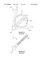
- FIG. 2Ashows a top view of some significant components of a conditioning sub-assembly 200 , which may be integrated into a CMP apparatus such as the IPEC 676.
- Conditioning sub-assembly 200includes a polishing pad 202 and a conditioning arm 204 that is disposed above polishing pad 202 and capable of pivoting about a pivoting point 206 .
- Conditioning arm 204is typically longer in length than a diameter of the polishing pad.
- FIG. 2Bshows a bottom view of conditioning arm 204 of FIG. 2 A.
- the bottom surface of conditioning arm 204includes a plurality of diamond abrasive particles 208 , which are substantially uniformly arranged on the conditioning arm such that if conditioning arm 204 contacts polishing pad 202 , abrasive particles 208 engage with a substantial portion of the polishing pad.
- conditioning arm 204is lowered automatically to contact a polishing pad 202 , which may be rotating or in orbital state.
- a pneumatic cylinder(not shown to simplify illustration) may then apply a downward force on conditioning arm 204 such that abrasive particles 208 contact and engage with a substantial portion of polishing pad 202 .
- conditioning arm 204pivots on pivoting end 206 and sweeps back and forth across polishing pad 202 like a “windshield wiper blade” from a first position 204 ′ (shown by dashed lines) at one end of the polishing pad to a second position 204 ⁇ (shown by dashed lines) at the other end of the polishing pad.
- This mechanical action of conditioning arm 204allows abrasive particles 208 to break up and remove the glazed or accumulated particles coated on the polishing pad surface.
- a fine polishingalso referred to as buffing
- buffingtypically uses a relatively soft pad formed, for example, from polyurethane impregnated felt.
- An exampleis the PolytexTM pad available from Rodel Corp. of Newark, Del.
- Buffingalso typically uses deionised water or may be assisted by a conventional oxide slurry.
- FIG. 3is a simplified top view of a typical multi-station CMP apparatus, such as the IPEC 676 or 776, described previously.
- the CMP apparatus 300has four polishing stations 302 , 304 , 306 and 308 , each with a polishing pad 310 and the other associated features described with reference to FIG. 1 (not shown in this view to simplify illustration).
- the apparatus 300also includes two conditioning sub-assemblies 320 and 322 , such as described with reference to FIGS. 2A and 2B, each of which service two polishing stations. For example, as shown in FIG.
- conditioning sub-assembly 320services polishing stations 302 and 304 .
- Each conditioning sub-assembly 320includes a conditioning arm 324 that may be swung out above a polishing pad polishing pad 202 by pivoting about a pivoting point 326 .
- one of the four stations on the CMP apparatusis typically dedicated to buffing, or a separate buffing station must be provided in addition to the polishing stations. This reduces the number of polishing stations available on the apparatus, or requires that the wafer be moved to a separate buffing station for buffing, both of which result in a significant reduction in the through-put capacity of the machine. Moreover, since a polishing pad must be conditioned following each wafer polishing, that pad is unavailable to receive another wafer for polishing until conditioning is complete. This is a further impediment to CMP efficiency.
- the present inventionprovides an apparatus and method for concurrently pad conditioning and wafer buffing on a single station of a CMP apparatus.
- the apparatusincludes a two-sided conditioning/buffing device having a pad conditioner on one side and a buff pad on the other.
- the deviceis inserted between a polishing pad and a polished wafer following CMP.
- a differential velocityis developed between the pad conditioner and the polishing pad, for example, by contacting the pad conditioner with a rotating or orbiting polishing pad.
- the polished waferis contacted with the buff pad on the other side of the device, and a differential velocity is developed between the two, for example, by rotating the wafer, so that the wafer is buffed.
- the finished waferis removed from the buffing pad and stored or removed from the CMP apparatus, and the conditioning/buffing device is removed and positioned away from the polishing pad, which is now ready to receive and polish another wafer.
- This concurrent conditioning and buffingallows all stations on a CMP apparatus to be used for polishing, and improves the through-put of the apparatus.
- the inventionprovides a device for concurrently pad conditioning and wafer buffing at a single station on a chemical mechanical polishing apparatus.
- the deviceincludes a positioning mechanism for positioning the device within the apparatus, and a body connected to one end of the positioning mechanism.
- the bodyhas a buffing pad on one of its upper or lower surfaces and a pad conditioner on the other surface.
- the bodymay also contain one or more transport lines for conditioning and/or buffing supplies.
- the inventionalso provides a chemical mechanical polishing apparatus.
- the apparatusincludes a wafer carrier, one or more polishing pads, each polishing pad at a polishing station, and one or more devices for concurrently pad conditioning and wafer buffing at a single station on a chemical mechanical polishing apparatus.
- Each deviceincludes a positioning mechanism for positioning the device within the apparatus, and a body connected to one end of the positioning mechanism.
- the bodyhas a buffing pad on one of its upper or lower surfaces and a pad conditioner on the other surface.
- the bodymay also contain one or more transport lines for conditioning and/or buffing supplies.
- the inventionfurther provides a chemical mechanical polishing apparatus module.
- the moduleincludes one or more polishing pads, each polishing pad at a polishing station, and one or more devices for concurrently pad conditioning and wafer buffing at a single station on a chemical mechanical polishing apparatus module.
- Each deviceincludes a positioning mechanism for positioning the device relative to the module, and a body connected to one end of the positioning mechanism.
- the bodyhas a buffing pad on one of its upper or lower surfaces and a pad conditioner on the other surface.
- the devicemay also contain one or more transport lines for conditioning and/or buffing supplies.
- the inventionprovides a process for chemical mechanical polishing of a semiconductor wafer.
- the methodinvolves providing a semiconductor wafer to a chemical mechanical polishing apparatus, polishing the wafer by contacting it with a polishing pad at a station on the apparatus, and concurrently, conditioning the polishing pad and buffing the wafer at the station on the apparatus.
- the inventionfurther comprises a process for chemical mechanical polishing of a semiconductor wafer on an apparatus in accordance with the present invention.
- the methodinvolves providing a semiconductor wafer to a chemical mechanical polishing apparatus and polishing said wafer by contacting it with a polishing pad at a station on said apparatus.
- the waferis then removed from the polishing pad, and a device having a pad conditioner on one of its upper or lower sides and a buff pad its other side is positioned between the wafer and the polishing pad.
- the pad conditioneris contacted with the polishing pad and the wafer is contacted with the buff pad.
- the polishing padis conditioned and the wafer is buffed.
- FIG. 1depicts a cross-sectional view of a typical chemical mechanical polishing apparatus.
- FIG. 2Adepicts a top plan view of a typical pad conditioning sub-assembly for use in chemical mechanical polishing.
- FIG. 2Bdepicts a bottom view of the conditioning arm of the sub-assembly of FIG. 2 A.
- FIG. 3depicts a simplified top view of a typical multi-station CMP apparatus.
- FIG. 4depicts a cross-sectional view of a conditioning/buffing device integrated with chemical mechanical polishing apparatus according to a preferred embodiment of the present invention.
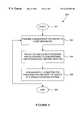
- FIG. 5depicts a flow chart illustrating a generalized process of concurrently pad conditioning and wafer buffing according to a preferred embodiment of the present invention.
- FIG. 6depicts a flow chart illustrating a process of concurrently pad conditioning and wafer buffing using a device in accordance with a preferred embodiment of the present invention.
- the present inventionprovides an apparatus and method for concurrently pad conditioning and wafer buffing on a single station of a CMP apparatus.
- numerous specific detailsare set forth in order to fully illustrate preferred embodiments of the present invention. It will be apparent, however, that the present invention may be practiced without limitation to some specific details presented herein.
- FIG. 4shows a cross-sectional view of a conditioning/buffing device according to a preferred embodiment of the present invention, integrated with chemical mechanical polishing apparatus.
- the device 400has a body 402 having an upper side 404 and a lower side 406 when the device is deployed in its active position, as shown in FIG. 4 .
- the terms “upper” and “lower”are relative, and may be interchangeable.
- the device 400On its upper side 404 , the device 400 has a buffing pad 408 , such as the PolytexTM pad described above.
- the pad 408will typically contain small holes (not shown) for water and/or buffing slurry to pass through during buffing.
- the buffing pad 408may be mounted on the body 402 of the device 400 in conventional ways well known to those of skill in the art. For example, buffing pads may have pressure sensitive adhesive (PSA) backings.
- PSApressure sensitive adhesive
- the device 400On its lower side 406 , the device 400 has a pad conditioner 410 , such as a conditioning arm or an abrasive disk coated or impregnated with diamond grit on its surface 412 which faces the polishing pad 414 .
- the pad conditioner 410like the buffing pad 408 , may have a conventional mechanism well known in the art, such as the conditioning sub-assembly described above.
- the pad conditioner 410should be mounted on the body 402 of the device 400 so that it contacts the polishing pad 414 when the device 400 is lowered onto a polishing pad 414 for conditioning.
- the device 400may be integrated with an otherwise conventional CMP apparatus, such as an IPEC 676 or 776.
- an apparatusmay be composed of a plurality of modules, for example, an upper module which includes a wafer carrier mechanism, and a lower module which contains one or more polishing stations, and conditioning and buffing mechanisms.
- the device 400is intended to replace conventional conditioning and buffing mechanisms which might otherwise be included on the conventional CMP apparatus or apparatus module.
- FIG. 4shows only that portion of a CMP apparatus 420 adjacent to a polishing station 422 .
- the term “apparatus 420 ” in the descriptionshould be understood to also refer to a module of a CMP apparatus where such an apparatus is composed of modules.
- the body 402 of the device 400may be connected by an articulated arm assembly 416 to an otherwise conventional CMP apparatus (or apparatus module) 420 , such as an IPEC 676 or 776, at a location adjacent to a polishing station 422 .
- the arm 416is capable of moving the body 402 of the device 400 into an active position between the wafer 432 and the polishing pad 414 during concurrent conditioning and buffing (as shown in FIG. 4 ), and into an inactive position, away from the polishing station 422 when the device 400 is not in use.
- the arm 416is preferably able to move the body 402 laterally and vertically so that it can oscillate the body and apply the appropriate down force during conditioning/buffing.
- the arm 416is also preferably able to rotate the body 402 from its horizontal active position to a vertical position for ease of storage when it is inactive.
- the device 400preferably includes one or more transport lines 418 for providing water, slurry, air, electricity and other conditioning and buffing needs to the buffing pad 408 and the pad conditioner 410 located on upper and lower surfaces of the body 402 , respectively, during concurrent conditioning Ind buffing.
- the lines 418are routed from the CMP apparatus 420 to the body 402 of the device 400 through the arm 416 connecting the device 400 to the apparatus 420 .
- the selection and installation of such transport lines 418are well within the skill of those skilled in the art, and the lines 418 may also be routed differently within the scope of the present invention.
- the deviceis preferably integrated with an otherwise conventional CMP apparatus 420 , such as an IPEC 676 or 776, a portion of which is shown in FIG. 4 .
- the figureshows a portion of one of four polishing stations 422 on the CMP apparatus 420 .
- the apparatus 420includes a conventional chuck mechanism 424 supporting the polishing pad 414 and a conventional wafer carrier mechanism 430 , as illustrated described in more detail, for example, in and with reference to FIG. 1 .
- the device 400 and apparatus 420operate in concert to provide appropriate differential velocity between the polishing pad 414 and the pad conditioner 410 , preferably about 30 to 250 feet/minute, and the wafer 432 and the buffing pad 408 , preferably about 30 to 80 RPM to accomplish the conditioning and buffing concurrently.
- the device 400 and apparatus 420also operate in concert to provide the appropriate down force for both operations, typically about 2-5 psi.
- the device 400 of the present inventionmay be used to perform joint operations on a single polishing station other than conditioning and buffing.
- polishing operationsother than buffing may be performed in conjunction with conditioning according to the present invention.
- FIG. 5shows a flow chart depicting the steps of a generalized method of concurrently pad conditioning and wafer buffing in chemical mechanical polishing in accordance with a preferred embodiment of the present invention.
- the method 500starts at 501 and at step 502 a semiconductor wafer is provided to CMP apparatus.
- the waferis polished on a polishing pad according to conventional CMP procedures, without buffing.
- the polishing padis conditioned and the wafer is buffed concurrently at a single polishing station.
- the processmay return to step 502 for the next wafer, or it may be completed at 508 .
- processes according to the present inventionmay include further steps.
- a device according to the present inventionmay be used following completion of conventional CMP, in accordance with the generalized method described above.
- a semiconductor waferis polished according to conventional procedures well known in the art, as described, for example, in Joseph M. Steigerwald, et aL, Chemical Mechanical Planarization of Microelectronic Materials , John Wiley & Sons, New York (1997), at a step 602 .
- a polished wafer 432 from a station 422 of a CMP apparatus 420is lifted from a polishing pad 414 , typically by a wafer carrier 430 .
- the conditioning/buffing device 400 of the present inventionis then positioned between the lifted wafer 432 and the polishing pad 414 at a step 606 .
- the lower surface 406 of the conditioning/buffing device 400which is equipped with the pad conditioner 410 is lowered onto the polishing pad 414 by the arm 416 with an appropriate amount of down force for the conditioning procedure, typically 2-5 psi.
- the wafer 432is lowered onto the buffing pad 408 of the device 400 , typically by a wafer carrier 430 , with the appropriate down force for buffing operations.
- steps 608 and 610may also take place concurrently, or may be reversed within the scope of the present invention.
- the polishing pad 414is conditioned as the wafer 432 is buffed.
- the device 400 and apparatus 420act in concert to provide the appropriate differential velocity between the polishing pad 414 and pad conditioner 410 of the device 400 , and the wafer 432 and the buffing pad 408 of the device 400 .
- the chuck 424may rotate and/or orbit the polishing pad 414
- the wafer carrier 430may rotate and/or oscillate the wafer 432 .
- the device 400may maintain a stationary position during the conditioning/buffing operations, or, more preferably, it may oscillate (as in conventional pad conditioning) in order to increase the differential velocities and enhance the conditioning and buffing effects.
- the buffed wafer 432is lifted, typically by the wafer carrier 430 , from the buffing pad 408 and stored or removed from the CMP apparatus 420 , at a step 614 .
- the device 400is lifted from the polishing pad 410 by the arm 416 , at a step 616 . Then, the device 400 is positioned away from the polishing station 422 to provide access to the station 422 for another wafer (not shown). The process flow concludes at 618 .
- CMP apparatusessuch as the IPEC 676 and 776 may be adapted to integrate a conditioning/buffing device in accordance with the present invention.
- the devicewill be mounted so that it may service a plurality of polishing stations on the apparatus.
- the ratio of devices to stationsshould not be so low that a station is inoperative for an unacceptable period while waiting for a device to service another station.
- it is believed that one conditioning/buffing device for every two polishing stationswould be optimal.
- the inventionis not so limited, however, and the optimal ratio may vary depending on process conditions and parameters.
- the inventionallows all stations on a CMP apparatus to be dedicated to polishing, the number of different polishing operations (for instance, using different polishing pads and buffing pads) on a single CMP apparatus may be maximized.
Landscapes
- Engineering & Computer Science (AREA)
- Mechanical Engineering (AREA)
- Mechanical Treatment Of Semiconductor (AREA)
- Finish Polishing, Edge Sharpening, And Grinding By Specific Grinding Devices (AREA)
Abstract
Description
Claims (14)
Priority Applications (1)
| Application Number | Priority Date | Filing Date | Title |
|---|---|---|---|
| US08/942,006US6234883B1 (en) | 1997-10-01 | 1997-10-01 | Method and apparatus for concurrent pad conditioning and wafer buff in chemical mechanical polishing |
Applications Claiming Priority (1)
| Application Number | Priority Date | Filing Date | Title |
|---|---|---|---|
| US08/942,006US6234883B1 (en) | 1997-10-01 | 1997-10-01 | Method and apparatus for concurrent pad conditioning and wafer buff in chemical mechanical polishing |
Publications (1)
| Publication Number | Publication Date |
|---|---|
| US6234883B1true US6234883B1 (en) | 2001-05-22 |
Family
ID=25477451
Family Applications (1)
| Application Number | Title | Priority Date | Filing Date |
|---|---|---|---|
| US08/942,006Expired - LifetimeUS6234883B1 (en) | 1997-10-01 | 1997-10-01 | Method and apparatus for concurrent pad conditioning and wafer buff in chemical mechanical polishing |
Country Status (1)
| Country | Link |
|---|---|
| US (1) | US6234883B1 (en) |
Cited By (11)
| Publication number | Priority date | Publication date | Assignee | Title |
|---|---|---|---|---|
| US6409580B1 (en)* | 2001-03-26 | 2002-06-25 | Speedfam-Ipec Corporation | Rigid polishing pad conditioner for chemical mechanical polishing tool |
| US6764389B1 (en) | 2002-08-20 | 2004-07-20 | Lsi Logic Corporation | Conditioning bar assembly having an abrasion member supported on a polycarbonate member |
| US20050153561A1 (en)* | 1998-11-02 | 2005-07-14 | Applied Materials, Inc., A Delaware Corporation | Chemical mechanical polishing a substrate having a filler layer and a stop layer |
| US20060035568A1 (en)* | 2004-08-12 | 2006-02-16 | Dunn Freddie L | Polishing pad conditioners having abrasives and brush elements, and associated systems and methods |
| US20080271384A1 (en)* | 2006-09-22 | 2008-11-06 | Saint-Gobain Ceramics & Plastics, Inc. | Conditioning tools and techniques for chemical mechanical planarization |
| US20100248595A1 (en)* | 2009-03-24 | 2010-09-30 | Saint-Gobain Abrasives, Inc. | Abrasive tool for use as a chemical mechanical planarization pad conditioner |
| US20100330886A1 (en)* | 2009-06-02 | 2010-12-30 | Saint-Gobain Abrasives, Inc. | Corrosion-Resistant CMP Conditioning Tools and Methods for Making and Using Same |
| US20110097977A1 (en)* | 2009-08-07 | 2011-04-28 | Abrasive Technology, Inc. | Multiple-sided cmp pad conditioning disk |
| CN103182681A (en)* | 2011-12-28 | 2013-07-03 | 青岛嘉星晶电科技股份有限公司 | Rectifying device for millstone of double-sided grinder, and rectifying method thereof |
| US8951099B2 (en) | 2009-09-01 | 2015-02-10 | Saint-Gobain Abrasives, Inc. | Chemical mechanical polishing conditioner |
| US20220143781A1 (en)* | 2020-11-11 | 2022-05-12 | Disco Corporation | Grinding apparatus |
Citations (74)
| Publication number | Priority date | Publication date | Assignee | Title |
|---|---|---|---|---|
| US4793895A (en) | 1988-01-25 | 1988-12-27 | Ibm Corporation | In situ conductivity monitoring technique for chemical/mechanical planarization endpoint detection |
| US5036015A (en) | 1990-09-24 | 1991-07-30 | Micron Technology, Inc. | Method of endpoint detection during chemical/mechanical planarization of semiconductor wafers |
| US5081421A (en) | 1990-05-01 | 1992-01-14 | At&T Bell Laboratories | In situ monitoring technique and apparatus for chemical/mechanical planarization endpoint detection |
| US5081051A (en) | 1990-09-12 | 1992-01-14 | Intel Corporation | Method for conditioning the surface of a polishing pad |
| US5144711A (en) | 1991-03-25 | 1992-09-08 | Westech Systems, Inc. | Cleaning brush for semiconductor wafer |
| US5151584A (en) | 1988-07-20 | 1992-09-29 | Applied Materials, Inc. | Method and apparatus for endpoint detection in a semiconductor wafer etching system |
| US5169491A (en) | 1991-07-29 | 1992-12-08 | Micron Technology, Inc. | Method of etching SiO2 dielectric layers using chemical mechanical polishing techniques |
| US5196353A (en) | 1992-01-03 | 1993-03-23 | Micron Technology, Inc. | Method for controlling a semiconductor (CMP) process by measuring a surface temperature and developing a thermal image of the wafer |
| US5216843A (en) | 1992-09-24 | 1993-06-08 | Intel Corporation | Polishing pad conditioning apparatus for wafer planarization process |
| US5222329A (en) | 1992-03-26 | 1993-06-29 | Micron Technology, Inc. | Acoustical method and system for detecting and controlling chemical-mechanical polishing (CMP) depths into layers of conductors, semiconductors, and dielectric materials |
| US5240552A (en) | 1991-12-11 | 1993-08-31 | Micron Technology, Inc. | Chemical mechanical planarization (CMP) of a semiconductor wafer using acoustical waves for in-situ end point detection |
| US5245790A (en) | 1992-02-14 | 1993-09-21 | Lsi Logic Corporation | Ultrasonic energy enhanced chemi-mechanical polishing of silicon wafers |
| US5245794A (en) | 1992-04-09 | 1993-09-21 | Advanced Micro Devices, Inc. | Audio end point detector for chemical-mechanical polishing and method therefor |
| US5257478A (en) | 1990-03-22 | 1993-11-02 | Rodel, Inc. | Apparatus for interlayer planarization of semiconductor material |
| US5265378A (en) | 1992-07-10 | 1993-11-30 | Lsi Logic Corporation | Detecting the endpoint of chem-mech polishing and resulting semiconductor device |
| US5272115A (en) | 1991-01-09 | 1993-12-21 | Nec Corporation | Method of leveling the laminated surface of a semiconductor substrate |
| US5308438A (en) | 1992-01-30 | 1994-05-03 | International Business Machines Corporation | Endpoint detection apparatus and method for chemical/mechanical polishing |
| US5310455A (en) | 1992-07-10 | 1994-05-10 | Lsi Logic Corporation | Techniques for assembling polishing pads for chemi-mechanical polishing of silicon wafers |
| US5337015A (en) | 1993-06-14 | 1994-08-09 | International Business Machines Corporation | In-situ endpoint detection method and apparatus for chemical-mechanical polishing using low amplitude input voltage |
| US5389194A (en) | 1993-02-05 | 1995-02-14 | Lsi Logic Corporation | Methods of cleaning semiconductor substrates after polishing |
| US5399234A (en) | 1993-09-29 | 1995-03-21 | Motorola Inc. | Acoustically regulated polishing process |
| US5403228A (en) | 1992-07-10 | 1995-04-04 | Lsi Logic Corporation | Techniques for assembling polishing pads for silicon wafer polishing |
| US5405806A (en) | 1994-03-29 | 1995-04-11 | Motorola Inc. | Method for forming a metal silicide interconnect in an integrated circuit |
| US5439551A (en) | 1994-03-02 | 1995-08-08 | Micron Technology, Inc. | Chemical-mechanical polishing techniques and methods of end point detection in chemical-mechanical polishing processes |
| US5483568A (en) | 1994-11-03 | 1996-01-09 | Kabushiki Kaisha Toshiba | Pad condition and polishing rate monitor using fluorescence |
| US5492594A (en) | 1994-09-26 | 1996-02-20 | International Business Machines Corp. | Chemical-mechanical polishing tool with end point measurement station |
| US5531861A (en) | 1993-09-29 | 1996-07-02 | Motorola, Inc. | Chemical-mechanical-polishing pad cleaning process for use during the fabrication of semiconductor devices |
| US5536202A (en) | 1994-07-27 | 1996-07-16 | Texas Instruments Incorporated | Semiconductor substrate conditioning head having a plurality of geometries formed in a surface thereof for pad conditioning during chemical-mechanical polish |
| US5547417A (en) | 1994-03-21 | 1996-08-20 | Intel Corporation | Method and apparatus for conditioning a semiconductor polishing pad |
| US5554065A (en)* | 1995-06-07 | 1996-09-10 | Clover; Richmond B. | Vertically stacked planarization machine |
| US5559428A (en) | 1995-04-10 | 1996-09-24 | International Business Machines Corporation | In-situ monitoring of the change in thickness of films |
| US5561541A (en) | 1984-09-05 | 1996-10-01 | The United States Of America As Represented By The Secretary Of The Army | Frustrated total internal reflection optical power limiter |
| US5595526A (en) | 1994-11-30 | 1997-01-21 | Intel Corporation | Method and apparatus for endpoint detection in a chemical/mechanical process for polishing a substrate |
| US5597442A (en) | 1995-10-16 | 1997-01-28 | Taiwan Semiconductor Manufacturing Company Ltd. | Chemical/mechanical planarization (CMP) endpoint method using measurement of polishing pad temperature |
| US5609511A (en) | 1994-04-14 | 1997-03-11 | Hitachi, Ltd. | Polishing method |
| US5611943A (en)* | 1995-09-29 | 1997-03-18 | Intel Corporation | Method and apparatus for conditioning of chemical-mechanical polishing pads |
| US5626715A (en) | 1993-02-05 | 1997-05-06 | Lsi Logic Corporation | Methods of polishing semiconductor substrates |
| US5637185A (en) | 1995-03-30 | 1997-06-10 | Rensselaer Polytechnic Institute | Systems for performing chemical mechanical planarization and process for conducting same |
| US5639388A (en) | 1995-01-19 | 1997-06-17 | Ebara Corporation | Polishing endpoint detection method |
| US5644221A (en) | 1996-03-19 | 1997-07-01 | International Business Machines Corporation | Endpoint detection for chemical mechanical polishing using frequency or amplitude mode |
| US5643050A (en) | 1996-05-23 | 1997-07-01 | Industrial Technology Research Institute | Chemical/mechanical polish (CMP) thickness monitor |
| US5643046A (en) | 1994-02-21 | 1997-07-01 | Kabushiki Kaisha Toshiba | Polishing method and apparatus for detecting a polishing end point of a semiconductor wafer |
| US5647952A (en) | 1996-04-01 | 1997-07-15 | Industrial Technology Research Institute | Chemical/mechanical polish (CMP) endpoint method |
| US5658183A (en) | 1993-08-25 | 1997-08-19 | Micron Technology, Inc. | System for real-time control of semiconductor wafer polishing including optical monitoring |
| US5660672A (en) | 1995-04-10 | 1997-08-26 | International Business Machines Corporation | In-situ monitoring of conductive films on semiconductor wafers |
| US5663797A (en) | 1996-05-16 | 1997-09-02 | Micron Technology, Inc. | Method and apparatus for detecting the endpoint in chemical-mechanical polishing of semiconductor wafers |
| US5664987A (en) | 1994-01-31 | 1997-09-09 | National Semiconductor Corporation | Methods and apparatus for control of polishing pad conditioning for wafer planarization |
| US5667424A (en) | 1996-09-25 | 1997-09-16 | Chartered Semiconductor Manufacturing Pte Ltd. | New chemical mechanical planarization (CMP) end point detection apparatus |
| US5668063A (en) | 1995-05-23 | 1997-09-16 | Watkins Johnson Company | Method of planarizing a layer of material |
| US5667629A (en) | 1996-06-21 | 1997-09-16 | Chartered Semiconductor Manufactuing Pte, Ltd. | Method and apparatus for determination of the end point in chemical mechanical polishing |
| US5667433A (en) | 1995-06-07 | 1997-09-16 | Lsi Logic Corporation | Keyed end effector for CMP pad conditioner |
| US5670410A (en) | 1996-09-25 | 1997-09-23 | Chartered Semiconductor Manufacturing Pte Ltd. | Method of forming integrated CMP stopper and analog capacitor |
| US5672091A (en) | 1994-12-22 | 1997-09-30 | Ebara Corporation | Polishing apparatus having endpoint detection device |
| US5674784A (en) | 1996-10-02 | 1997-10-07 | Taiwan Semiconductor Manufacturing Company, Ltd. | Method for forming polish stop layer for CMP process |
| US5695660A (en) | 1992-09-17 | 1997-12-09 | Luxtron Corporation | Optical techniques of measuring endpoint during the processing of material layers in an optically hostile environment |
| US5700180A (en) | 1993-08-25 | 1997-12-23 | Micron Technology, Inc. | System for real-time control of semiconductor wafer polishing |
| US5705435A (en) | 1996-08-09 | 1998-01-06 | Industrial Technology Research Institute | Chemical-mechanical polishing (CMP) apparatus |
| US5710076A (en) | 1996-09-03 | 1998-01-20 | Industrial Technology Research Institute | Method for fabricating a sub-half micron MOSFET device with global planarization of insulator filled shallow trenches, via the use of a bottom anti-reflective coating |
| US5712185A (en) | 1996-04-23 | 1998-01-27 | United Microelectronics | Method for forming shallow trench isolation |
| US5722875A (en) | 1995-05-30 | 1998-03-03 | Tokyo Electron Limited | Method and apparatus for polishing |
| US5741171A (en) | 1996-08-19 | 1998-04-21 | Sagitta Engineering Solutions, Ltd. | Precision polishing system |
| US5777739A (en) | 1996-02-16 | 1998-07-07 | Micron Technology, Inc. | Endpoint detector and method for measuring a change in wafer thickness in chemical-mechanical polishing of semiconductor wafers |
| US5785585A (en)* | 1995-09-18 | 1998-07-28 | International Business Machines Corporation | Polish pad conditioner with radial compensation |
| US5861055A (en) | 1995-12-29 | 1999-01-19 | Lsi Logic Corporation | Polishing composition for CMP operations |
| US5865666A (en) | 1997-08-20 | 1999-02-02 | Lsi Logic Corporation | Apparatus and method for polish removing a precise amount of material from a wafer |
| US5868608A (en) | 1996-08-13 | 1999-02-09 | Lsi Logic Corporation | Subsonic to supersonic and ultrasonic conditioning of a polishing pad in a chemical mechanical polishing apparatus |
| US5882120A (en) | 1996-09-06 | 1999-03-16 | Kapak Corp. | Bag construction for distributing material |
| US5888120A (en) | 1997-09-29 | 1999-03-30 | Lsi Logic Corporation | Method and apparatus for chemical mechanical polishing |
| US5893756A (en) | 1997-08-26 | 1999-04-13 | Lsi Logic Corporation | Use of ethylene glycol as a corrosion inhibitor during cleaning after metal chemical mechanical polishing |
| US5931719A (en) | 1997-08-25 | 1999-08-03 | Lsi Logic Corporation | Method and apparatus for using pressure differentials through a polishing pad to improve performance in chemical mechanical polishing |
| US5948697A (en) | 1996-05-23 | 1999-09-07 | Lsi Logic Corporation | Catalytic acceleration and electrical bias control of CMP processing |
| US5957757A (en) | 1997-10-30 | 1999-09-28 | Lsi Logic Corporation | Conditioning CMP polishing pad using a high pressure fluid |
| US5990010A (en)* | 1997-04-08 | 1999-11-23 | Lsi Logic Corporation | Pre-conditioning polishing pads for chemical-mechanical polishing |
| US6093280A (en)* | 1997-08-18 | 2000-07-25 | Lsi Logic Corporation | Chemical-mechanical polishing pad conditioning systems |
- 1997
- 1997-10-01USUS08/942,006patent/US6234883B1/ennot_activeExpired - Lifetime
Patent Citations (77)
| Publication number | Priority date | Publication date | Assignee | Title |
|---|---|---|---|---|
| US5561541A (en) | 1984-09-05 | 1996-10-01 | The United States Of America As Represented By The Secretary Of The Army | Frustrated total internal reflection optical power limiter |
| US4793895A (en) | 1988-01-25 | 1988-12-27 | Ibm Corporation | In situ conductivity monitoring technique for chemical/mechanical planarization endpoint detection |
| US5151584A (en) | 1988-07-20 | 1992-09-29 | Applied Materials, Inc. | Method and apparatus for endpoint detection in a semiconductor wafer etching system |
| US5257478A (en) | 1990-03-22 | 1993-11-02 | Rodel, Inc. | Apparatus for interlayer planarization of semiconductor material |
| US5081421A (en) | 1990-05-01 | 1992-01-14 | At&T Bell Laboratories | In situ monitoring technique and apparatus for chemical/mechanical planarization endpoint detection |
| US5081051A (en) | 1990-09-12 | 1992-01-14 | Intel Corporation | Method for conditioning the surface of a polishing pad |
| US5036015A (en) | 1990-09-24 | 1991-07-30 | Micron Technology, Inc. | Method of endpoint detection during chemical/mechanical planarization of semiconductor wafers |
| US5272115A (en) | 1991-01-09 | 1993-12-21 | Nec Corporation | Method of leveling the laminated surface of a semiconductor substrate |
| US5144711A (en) | 1991-03-25 | 1992-09-08 | Westech Systems, Inc. | Cleaning brush for semiconductor wafer |
| US5169491A (en) | 1991-07-29 | 1992-12-08 | Micron Technology, Inc. | Method of etching SiO2 dielectric layers using chemical mechanical polishing techniques |
| US5240552A (en) | 1991-12-11 | 1993-08-31 | Micron Technology, Inc. | Chemical mechanical planarization (CMP) of a semiconductor wafer using acoustical waves for in-situ end point detection |
| US5196353A (en) | 1992-01-03 | 1993-03-23 | Micron Technology, Inc. | Method for controlling a semiconductor (CMP) process by measuring a surface temperature and developing a thermal image of the wafer |
| US5308438A (en) | 1992-01-30 | 1994-05-03 | International Business Machines Corporation | Endpoint detection apparatus and method for chemical/mechanical polishing |
| US5245790A (en) | 1992-02-14 | 1993-09-21 | Lsi Logic Corporation | Ultrasonic energy enhanced chemi-mechanical polishing of silicon wafers |
| US5222329A (en) | 1992-03-26 | 1993-06-29 | Micron Technology, Inc. | Acoustical method and system for detecting and controlling chemical-mechanical polishing (CMP) depths into layers of conductors, semiconductors, and dielectric materials |
| US5245794A (en) | 1992-04-09 | 1993-09-21 | Advanced Micro Devices, Inc. | Audio end point detector for chemical-mechanical polishing and method therefor |
| US5265378A (en) | 1992-07-10 | 1993-11-30 | Lsi Logic Corporation | Detecting the endpoint of chem-mech polishing and resulting semiconductor device |
| US5310455A (en) | 1992-07-10 | 1994-05-10 | Lsi Logic Corporation | Techniques for assembling polishing pads for chemi-mechanical polishing of silicon wafers |
| US5321304A (en) | 1992-07-10 | 1994-06-14 | Lsi Logic Corporation | Detecting the endpoint of chem-mech polishing, and resulting semiconductor device |
| US5516400A (en) | 1992-07-10 | 1996-05-14 | Lsi Logic Corporation | Techniques for assembling polishing pads for chemical-mechanical polishing of silicon wafers |
| US5624304A (en) | 1992-07-10 | 1997-04-29 | Lsi Logic, Inc. | Techniques for assembling polishing pads for chemi-mechanical polishing of silicon wafers |
| US5403228A (en) | 1992-07-10 | 1995-04-04 | Lsi Logic Corporation | Techniques for assembling polishing pads for silicon wafer polishing |
| US5695660A (en) | 1992-09-17 | 1997-12-09 | Luxtron Corporation | Optical techniques of measuring endpoint during the processing of material layers in an optically hostile environment |
| US5216843A (en) | 1992-09-24 | 1993-06-08 | Intel Corporation | Polishing pad conditioning apparatus for wafer planarization process |
| US5626715A (en) | 1993-02-05 | 1997-05-06 | Lsi Logic Corporation | Methods of polishing semiconductor substrates |
| US5389194A (en) | 1993-02-05 | 1995-02-14 | Lsi Logic Corporation | Methods of cleaning semiconductor substrates after polishing |
| US5337015A (en) | 1993-06-14 | 1994-08-09 | International Business Machines Corporation | In-situ endpoint detection method and apparatus for chemical-mechanical polishing using low amplitude input voltage |
| US5658183A (en) | 1993-08-25 | 1997-08-19 | Micron Technology, Inc. | System for real-time control of semiconductor wafer polishing including optical monitoring |
| US5700180A (en) | 1993-08-25 | 1997-12-23 | Micron Technology, Inc. | System for real-time control of semiconductor wafer polishing |
| US5531861A (en) | 1993-09-29 | 1996-07-02 | Motorola, Inc. | Chemical-mechanical-polishing pad cleaning process for use during the fabrication of semiconductor devices |
| US5399234A (en) | 1993-09-29 | 1995-03-21 | Motorola Inc. | Acoustically regulated polishing process |
| US5664987A (en) | 1994-01-31 | 1997-09-09 | National Semiconductor Corporation | Methods and apparatus for control of polishing pad conditioning for wafer planarization |
| US5643046A (en) | 1994-02-21 | 1997-07-01 | Kabushiki Kaisha Toshiba | Polishing method and apparatus for detecting a polishing end point of a semiconductor wafer |
| US5439551A (en) | 1994-03-02 | 1995-08-08 | Micron Technology, Inc. | Chemical-mechanical polishing techniques and methods of end point detection in chemical-mechanical polishing processes |
| US5547417A (en) | 1994-03-21 | 1996-08-20 | Intel Corporation | Method and apparatus for conditioning a semiconductor polishing pad |
| US5405806A (en) | 1994-03-29 | 1995-04-11 | Motorola Inc. | Method for forming a metal silicide interconnect in an integrated circuit |
| US5609511A (en) | 1994-04-14 | 1997-03-11 | Hitachi, Ltd. | Polishing method |
| US5536202A (en) | 1994-07-27 | 1996-07-16 | Texas Instruments Incorporated | Semiconductor substrate conditioning head having a plurality of geometries formed in a surface thereof for pad conditioning during chemical-mechanical polish |
| US5492594A (en) | 1994-09-26 | 1996-02-20 | International Business Machines Corp. | Chemical-mechanical polishing tool with end point measurement station |
| US5483568A (en) | 1994-11-03 | 1996-01-09 | Kabushiki Kaisha Toshiba | Pad condition and polishing rate monitor using fluorescence |
| US5595526A (en) | 1994-11-30 | 1997-01-21 | Intel Corporation | Method and apparatus for endpoint detection in a chemical/mechanical process for polishing a substrate |
| US5672091A (en) | 1994-12-22 | 1997-09-30 | Ebara Corporation | Polishing apparatus having endpoint detection device |
| US5639388A (en) | 1995-01-19 | 1997-06-17 | Ebara Corporation | Polishing endpoint detection method |
| US5637185A (en) | 1995-03-30 | 1997-06-10 | Rensselaer Polytechnic Institute | Systems for performing chemical mechanical planarization and process for conducting same |
| US5660672A (en) | 1995-04-10 | 1997-08-26 | International Business Machines Corporation | In-situ monitoring of conductive films on semiconductor wafers |
| US5559428A (en) | 1995-04-10 | 1996-09-24 | International Business Machines Corporation | In-situ monitoring of the change in thickness of films |
| US5668063A (en) | 1995-05-23 | 1997-09-16 | Watkins Johnson Company | Method of planarizing a layer of material |
| US5722875A (en) | 1995-05-30 | 1998-03-03 | Tokyo Electron Limited | Method and apparatus for polishing |
| US5554065A (en)* | 1995-06-07 | 1996-09-10 | Clover; Richmond B. | Vertically stacked planarization machine |
| US5667433A (en) | 1995-06-07 | 1997-09-16 | Lsi Logic Corporation | Keyed end effector for CMP pad conditioner |
| US5785585A (en)* | 1995-09-18 | 1998-07-28 | International Business Machines Corporation | Polish pad conditioner with radial compensation |
| US5611943A (en)* | 1995-09-29 | 1997-03-18 | Intel Corporation | Method and apparatus for conditioning of chemical-mechanical polishing pads |
| US5597442A (en) | 1995-10-16 | 1997-01-28 | Taiwan Semiconductor Manufacturing Company Ltd. | Chemical/mechanical planarization (CMP) endpoint method using measurement of polishing pad temperature |
| US5861055A (en) | 1995-12-29 | 1999-01-19 | Lsi Logic Corporation | Polishing composition for CMP operations |
| US5777739A (en) | 1996-02-16 | 1998-07-07 | Micron Technology, Inc. | Endpoint detector and method for measuring a change in wafer thickness in chemical-mechanical polishing of semiconductor wafers |
| US5644221A (en) | 1996-03-19 | 1997-07-01 | International Business Machines Corporation | Endpoint detection for chemical mechanical polishing using frequency or amplitude mode |
| US5647952A (en) | 1996-04-01 | 1997-07-15 | Industrial Technology Research Institute | Chemical/mechanical polish (CMP) endpoint method |
| US5712185A (en) | 1996-04-23 | 1998-01-27 | United Microelectronics | Method for forming shallow trench isolation |
| US5663797A (en) | 1996-05-16 | 1997-09-02 | Micron Technology, Inc. | Method and apparatus for detecting the endpoint in chemical-mechanical polishing of semiconductor wafers |
| US5643050A (en) | 1996-05-23 | 1997-07-01 | Industrial Technology Research Institute | Chemical/mechanical polish (CMP) thickness monitor |
| US5948697A (en) | 1996-05-23 | 1999-09-07 | Lsi Logic Corporation | Catalytic acceleration and electrical bias control of CMP processing |
| US5667629A (en) | 1996-06-21 | 1997-09-16 | Chartered Semiconductor Manufactuing Pte, Ltd. | Method and apparatus for determination of the end point in chemical mechanical polishing |
| US5705435A (en) | 1996-08-09 | 1998-01-06 | Industrial Technology Research Institute | Chemical-mechanical polishing (CMP) apparatus |
| US5868608A (en) | 1996-08-13 | 1999-02-09 | Lsi Logic Corporation | Subsonic to supersonic and ultrasonic conditioning of a polishing pad in a chemical mechanical polishing apparatus |
| US5741171A (en) | 1996-08-19 | 1998-04-21 | Sagitta Engineering Solutions, Ltd. | Precision polishing system |
| US5710076A (en) | 1996-09-03 | 1998-01-20 | Industrial Technology Research Institute | Method for fabricating a sub-half micron MOSFET device with global planarization of insulator filled shallow trenches, via the use of a bottom anti-reflective coating |
| US5882120A (en) | 1996-09-06 | 1999-03-16 | Kapak Corp. | Bag construction for distributing material |
| US5670410A (en) | 1996-09-25 | 1997-09-23 | Chartered Semiconductor Manufacturing Pte Ltd. | Method of forming integrated CMP stopper and analog capacitor |
| US5667424A (en) | 1996-09-25 | 1997-09-16 | Chartered Semiconductor Manufacturing Pte Ltd. | New chemical mechanical planarization (CMP) end point detection apparatus |
| US5674784A (en) | 1996-10-02 | 1997-10-07 | Taiwan Semiconductor Manufacturing Company, Ltd. | Method for forming polish stop layer for CMP process |
| US5990010A (en)* | 1997-04-08 | 1999-11-23 | Lsi Logic Corporation | Pre-conditioning polishing pads for chemical-mechanical polishing |
| US6093280A (en)* | 1997-08-18 | 2000-07-25 | Lsi Logic Corporation | Chemical-mechanical polishing pad conditioning systems |
| US5865666A (en) | 1997-08-20 | 1999-02-02 | Lsi Logic Corporation | Apparatus and method for polish removing a precise amount of material from a wafer |
| US5931719A (en) | 1997-08-25 | 1999-08-03 | Lsi Logic Corporation | Method and apparatus for using pressure differentials through a polishing pad to improve performance in chemical mechanical polishing |
| US5893756A (en) | 1997-08-26 | 1999-04-13 | Lsi Logic Corporation | Use of ethylene glycol as a corrosion inhibitor during cleaning after metal chemical mechanical polishing |
| US5888120A (en) | 1997-09-29 | 1999-03-30 | Lsi Logic Corporation | Method and apparatus for chemical mechanical polishing |
| US5957757A (en) | 1997-10-30 | 1999-09-28 | Lsi Logic Corporation | Conditioning CMP polishing pad using a high pressure fluid |
Non-Patent Citations (2)
| Title |
|---|
| "Avant Gaard 676", IPEC-Planar Bulletin #4500-104621, 1997. |
| "Avant Gaard 776", IPEC-Planar Bulletin #4500-104660, 1997. |
Cited By (16)
| Publication number | Priority date | Publication date | Assignee | Title |
|---|---|---|---|---|
| US20050153561A1 (en)* | 1998-11-02 | 2005-07-14 | Applied Materials, Inc., A Delaware Corporation | Chemical mechanical polishing a substrate having a filler layer and a stop layer |
| US6409580B1 (en)* | 2001-03-26 | 2002-06-25 | Speedfam-Ipec Corporation | Rigid polishing pad conditioner for chemical mechanical polishing tool |
| US6764389B1 (en) | 2002-08-20 | 2004-07-20 | Lsi Logic Corporation | Conditioning bar assembly having an abrasion member supported on a polycarbonate member |
| US20060035568A1 (en)* | 2004-08-12 | 2006-02-16 | Dunn Freddie L | Polishing pad conditioners having abrasives and brush elements, and associated systems and methods |
| US7033253B2 (en) | 2004-08-12 | 2006-04-25 | Micron Technology, Inc. | Polishing pad conditioners having abrasives and brush elements, and associated systems and methods |
| US20080271384A1 (en)* | 2006-09-22 | 2008-11-06 | Saint-Gobain Ceramics & Plastics, Inc. | Conditioning tools and techniques for chemical mechanical planarization |
| US20100248595A1 (en)* | 2009-03-24 | 2010-09-30 | Saint-Gobain Abrasives, Inc. | Abrasive tool for use as a chemical mechanical planarization pad conditioner |
| US8342910B2 (en) | 2009-03-24 | 2013-01-01 | Saint-Gobain Abrasives, Inc. | Abrasive tool for use as a chemical mechanical planarization pad conditioner |
| US9022840B2 (en) | 2009-03-24 | 2015-05-05 | Saint-Gobain Abrasives, Inc. | Abrasive tool for use as a chemical mechanical planarization pad conditioner |
| US8905823B2 (en) | 2009-06-02 | 2014-12-09 | Saint-Gobain Abrasives, Inc. | Corrosion-resistant CMP conditioning tools and methods for making and using same |
| US20100330886A1 (en)* | 2009-06-02 | 2010-12-30 | Saint-Gobain Abrasives, Inc. | Corrosion-Resistant CMP Conditioning Tools and Methods for Making and Using Same |
| US20110097977A1 (en)* | 2009-08-07 | 2011-04-28 | Abrasive Technology, Inc. | Multiple-sided cmp pad conditioning disk |
| US8951099B2 (en) | 2009-09-01 | 2015-02-10 | Saint-Gobain Abrasives, Inc. | Chemical mechanical polishing conditioner |
| CN103182681A (en)* | 2011-12-28 | 2013-07-03 | 青岛嘉星晶电科技股份有限公司 | Rectifying device for millstone of double-sided grinder, and rectifying method thereof |
| US20220143781A1 (en)* | 2020-11-11 | 2022-05-12 | Disco Corporation | Grinding apparatus |
| US11717934B2 (en)* | 2020-11-11 | 2023-08-08 | Disco Corporation | Annular frame cleaning accessory for grinding apparatus |
Similar Documents
| Publication | Publication Date | Title |
|---|---|---|
| US5902173A (en) | Polishing machine with efficient polishing and dressing | |
| US5522965A (en) | Compact system and method for chemical-mechanical polishing utilizing energy coupled to the polishing pad/water interface | |
| US6692338B1 (en) | Through-pad drainage of slurry during chemical mechanical polishing | |
| US6409580B1 (en) | Rigid polishing pad conditioner for chemical mechanical polishing tool | |
| KR100315722B1 (en) | Polishing machine for flattening substrate surface | |
| US6241585B1 (en) | Apparatus and method for chemical mechanical polishing | |
| US7749908B2 (en) | Edge removal of silicon-on-insulator transfer wafer | |
| US5755979A (en) | Application of semiconductor IC fabrication techniques to the manufacturing of a conditioning head for pad conditioning during chemical-mechanical polish | |
| KR100264756B1 (en) | Method for dressing pad, polishing apparatus and method for manufacturing semiconductor device | |
| US20060183410A1 (en) | Diamond conditioning of soft chemical mechanical planarization/polishing (CMP) polishing pads | |
| US6234883B1 (en) | Method and apparatus for concurrent pad conditioning and wafer buff in chemical mechanical polishing | |
| US6394886B1 (en) | Conformal disk holder for CMP pad conditioner | |
| US6439978B1 (en) | Substrate polishing system using roll-to-roll fixed abrasive | |
| US6106371A (en) | Effective pad conditioning | |
| JP2000353677A (en) | Chemical mechanical flattening system | |
| KR19980070998A (en) | Polishing apparatus, polishing member and polishing method | |
| JP2005103696A (en) | Polishing equipment | |
| EP0806267A1 (en) | Cross-hatched polishing pad for polishing substrates in a chemical mechanical polishing system | |
| US6857942B1 (en) | Apparatus and method for pre-conditioning a conditioning disc | |
| KR100590513B1 (en) | Chemical mechanical polishing apparatus and method | |
| US6300248B1 (en) | On-chip pad conditioning for chemical mechanical polishing | |
| US6558228B1 (en) | Method of unloading substrates in chemical-mechanical polishing apparatus | |
| US20020072307A1 (en) | Apparatus and method for chemical mechanical planarization using a fixed-abrasive polishing pad | |
| US6368186B1 (en) | Apparatus for mounting a rotational disk | |
| US6783441B2 (en) | Apparatus and method for transferring a torque from a rotating hub frame to a one-piece hub shaft |
Legal Events
| Date | Code | Title | Description |
|---|---|---|---|
| AS | Assignment | Owner name:LSI LOGIC CORPORATION, CALIFORNIA Free format text:ASSIGNMENT OF ASSIGNORS INTEREST;ASSIGNOR:BERMAN, MICHAEL J.;REEL/FRAME:011378/0734 Effective date:19970923 | |
| AS | Assignment | Owner name:INTEGRATED PROCESSING EQUIPMENT CORPORATION, ARIZO Free format text:ASSIGNMENT OF ASSIGNORS INTEREST;ASSIGNOR:HOLLAND, KAREY L.;REEL/FRAME:008875/0840 Effective date:19970925 | |
| STCF | Information on status: patent grant | Free format text:PATENTED CASE | |
| FPAY | Fee payment | Year of fee payment:4 | |
| FEPP | Fee payment procedure | Free format text:PAYOR NUMBER ASSIGNED (ORIGINAL EVENT CODE: ASPN); ENTITY STATUS OF PATENT OWNER: LARGE ENTITY Free format text:PAYER NUMBER DE-ASSIGNED (ORIGINAL EVENT CODE: RMPN); ENTITY STATUS OF PATENT OWNER: LARGE ENTITY | |
| FPAY | Fee payment | Year of fee payment:8 | |
| FPAY | Fee payment | Year of fee payment:12 | |
| AS | Assignment | Owner name:DEUTSCHE BANK AG NEW YORK BRANCH, AS COLLATERAL AG Free format text:PATENT SECURITY AGREEMENT;ASSIGNORS:LSI CORPORATION;AGERE SYSTEMS LLC;REEL/FRAME:032856/0031 Effective date:20140506 | |
| AS | Assignment | Owner name:LSI CORPORATION, CALIFORNIA Free format text:CHANGE OF NAME;ASSIGNOR:LSI LOGIC CORPORATION;REEL/FRAME:033102/0270 Effective date:20070406 | |
| AS | Assignment | Owner name:AVAGO TECHNOLOGIES GENERAL IP (SINGAPORE) PTE. LTD Free format text:ASSIGNMENT OF ASSIGNORS INTEREST;ASSIGNOR:LSI CORPORATION;REEL/FRAME:035390/0388 Effective date:20140814 | |
| AS | Assignment | Owner name:AGERE SYSTEMS LLC, PENNSYLVANIA Free format text:TERMINATION AND RELEASE OF SECURITY INTEREST IN PATENT RIGHTS (RELEASES RF 032856-0031);ASSIGNOR:DEUTSCHE BANK AG NEW YORK BRANCH, AS COLLATERAL AGENT;REEL/FRAME:037684/0039 Effective date:20160201 Owner name:LSI CORPORATION, CALIFORNIA Free format text:TERMINATION AND RELEASE OF SECURITY INTEREST IN PATENT RIGHTS (RELEASES RF 032856-0031);ASSIGNOR:DEUTSCHE BANK AG NEW YORK BRANCH, AS COLLATERAL AGENT;REEL/FRAME:037684/0039 Effective date:20160201 | |
| AS | Assignment | Owner name:BANK OF AMERICA, N.A., AS COLLATERAL AGENT, NORTH CAROLINA Free format text:PATENT SECURITY AGREEMENT;ASSIGNOR:AVAGO TECHNOLOGIES GENERAL IP (SINGAPORE) PTE. LTD.;REEL/FRAME:037808/0001 Effective date:20160201 Owner name:BANK OF AMERICA, N.A., AS COLLATERAL AGENT, NORTH Free format text:PATENT SECURITY AGREEMENT;ASSIGNOR:AVAGO TECHNOLOGIES GENERAL IP (SINGAPORE) PTE. LTD.;REEL/FRAME:037808/0001 Effective date:20160201 | |
| AS | Assignment | Owner name:AVAGO TECHNOLOGIES GENERAL IP (SINGAPORE) PTE. LTD., SINGAPORE Free format text:TERMINATION AND RELEASE OF SECURITY INTEREST IN PATENTS;ASSIGNOR:BANK OF AMERICA, N.A., AS COLLATERAL AGENT;REEL/FRAME:041710/0001 Effective date:20170119 Owner name:AVAGO TECHNOLOGIES GENERAL IP (SINGAPORE) PTE. LTD Free format text:TERMINATION AND RELEASE OF SECURITY INTEREST IN PATENTS;ASSIGNOR:BANK OF AMERICA, N.A., AS COLLATERAL AGENT;REEL/FRAME:041710/0001 Effective date:20170119 | |
| AS | Assignment | Owner name:BELL SEMICONDUCTOR, LLC, ILLINOIS Free format text:ASSIGNMENT OF ASSIGNORS INTEREST;ASSIGNORS:AVAGO TECHNOLOGIES GENERAL IP (SINGAPORE) PTE. LTD.;BROADCOM CORPORATION;REEL/FRAME:044886/0608 Effective date:20171208 | |
| AS | Assignment | Owner name:CORTLAND CAPITAL MARKET SERVICES LLC, AS COLLATERA Free format text:SECURITY INTEREST;ASSIGNORS:HILCO PATENT ACQUISITION 56, LLC;BELL SEMICONDUCTOR, LLC;BELL NORTHERN RESEARCH, LLC;REEL/FRAME:045216/0020 Effective date:20180124 | |
| AS | Assignment | Owner name:BELL NORTHERN RESEARCH, LLC, ILLINOIS Free format text:RELEASE BY SECURED PARTY;ASSIGNOR:CORTLAND CAPITAL MARKET SERVICES LLC;REEL/FRAME:059720/0719 Effective date:20220401 Owner name:BELL SEMICONDUCTOR, LLC, ILLINOIS Free format text:RELEASE BY SECURED PARTY;ASSIGNOR:CORTLAND CAPITAL MARKET SERVICES LLC;REEL/FRAME:059720/0719 Effective date:20220401 Owner name:HILCO PATENT ACQUISITION 56, LLC, ILLINOIS Free format text:RELEASE BY SECURED PARTY;ASSIGNOR:CORTLAND CAPITAL MARKET SERVICES LLC;REEL/FRAME:059720/0719 Effective date:20220401 |