US6234797B1 - Dental implant and method for installing the same - Google Patents
Dental implant and method for installing the sameDownload PDFInfo
- Publication number
- US6234797B1 US6234797B1US09/416,355US41635599AUS6234797B1US 6234797 B1US6234797 B1US 6234797B1US 41635599 AUS41635599 AUS 41635599AUS 6234797 B1US6234797 B1US 6234797B1
- Authority
- US
- United States
- Prior art keywords
- thread
- dental implant
- implant
- proximal
- distal
- Prior art date
- Legal status (The legal status is an assumption and is not a legal conclusion. Google has not performed a legal analysis and makes no representation as to the accuracy of the status listed.)
- Expired - Fee Related
Links
Images


Classifications
- A—HUMAN NECESSITIES
- A61—MEDICAL OR VETERINARY SCIENCE; HYGIENE
- A61C—DENTISTRY; APPARATUS OR METHODS FOR ORAL OR DENTAL HYGIENE
- A61C8/00—Means to be fixed to the jaw-bone for consolidating natural teeth or for fixing dental prostheses thereon; Dental implants; Implanting tools
- A61C8/0018—Means to be fixed to the jaw-bone for consolidating natural teeth or for fixing dental prostheses thereon; Dental implants; Implanting tools characterised by the shape
- A61C8/0022—Self-screwing
- A—HUMAN NECESSITIES
- A21—BAKING; EDIBLE DOUGHS
- A21D—TREATMENT OF FLOUR OR DOUGH FOR BAKING, e.g. BY ADDITION OF MATERIALS; BAKING; BAKERY PRODUCTS
- A21D2/00—Treatment of flour or dough by adding materials thereto before or during baking
- A21D2/08—Treatment of flour or dough by adding materials thereto before or during baking by adding organic substances
- A21D2/14—Organic oxygen compounds
- A21D2/18—Carbohydrates
- A21D2/186—Starches; Derivatives thereof
- A—HUMAN NECESSITIES
- A23—FOODS OR FOODSTUFFS; TREATMENT THEREOF, NOT COVERED BY OTHER CLASSES
- A23C—DAIRY PRODUCTS, e.g. MILK, BUTTER OR CHEESE; MILK OR CHEESE SUBSTITUTES; MAKING OR TREATMENT THEREOF
- A23C19/00—Cheese; Cheese preparations; Making thereof
- A23C19/06—Treating cheese curd after whey separation; Products obtained thereby
- A23C19/068—Particular types of cheese
- A23C19/08—Process cheese preparations; Making thereof, e.g. melting, emulsifying, sterilizing
- A23C19/082—Adding substances to the curd before or during melting; Melting salts
- A—HUMAN NECESSITIES
- A23—FOODS OR FOODSTUFFS; TREATMENT THEREOF, NOT COVERED BY OTHER CLASSES
- A23D—EDIBLE OILS OR FATS, e.g. MARGARINES, SHORTENINGS OR COOKING OILS
- A23D7/00—Edible oil or fat compositions containing an aqueous phase, e.g. margarines
- A23D7/005—Edible oil or fat compositions containing an aqueous phase, e.g. margarines characterised by ingredients other than fatty acid triglycerides
- A23D7/0056—Spread compositions
- A—HUMAN NECESSITIES
- A23—FOODS OR FOODSTUFFS; TREATMENT THEREOF, NOT COVERED BY OTHER CLASSES
- A23D—EDIBLE OILS OR FATS, e.g. MARGARINES, SHORTENINGS OR COOKING OILS
- A23D7/00—Edible oil or fat compositions containing an aqueous phase, e.g. margarines
- A23D7/015—Reducing calorie content; Reducing fat content, e.g. "halvarines"
- A—HUMAN NECESSITIES
- A61—MEDICAL OR VETERINARY SCIENCE; HYGIENE
- A61C—DENTISTRY; APPARATUS OR METHODS FOR ORAL OR DENTAL HYGIENE
- A61C8/00—Means to be fixed to the jaw-bone for consolidating natural teeth or for fixing dental prostheses thereon; Dental implants; Implanting tools
- A61C8/0018—Means to be fixed to the jaw-bone for consolidating natural teeth or for fixing dental prostheses thereon; Dental implants; Implanting tools characterised by the shape
- A61C8/0022—Self-screwing
- A61C8/0025—Self-screwing with multiple threads
- A—HUMAN NECESSITIES
- A61—MEDICAL OR VETERINARY SCIENCE; HYGIENE
- A61C—DENTISTRY; APPARATUS OR METHODS FOR ORAL OR DENTAL HYGIENE
- A61C8/00—Means to be fixed to the jaw-bone for consolidating natural teeth or for fixing dental prostheses thereon; Dental implants; Implanting tools
- A61C8/0048—Connecting the upper structure to the implant, e.g. bridging bars
- A61C8/0075—Implant heads specially designed for receiving an upper structure
Definitions
- the present inventionrelates generally to a dental implant, and more particularly to a dental implant with a thread design and structure which provides for dramatically improved loading to thereby facilitate an immediate load implant or an implant with dramatically reduced healing time.
- the present inventionalso relates to a method of installing the above identified implant.
- Dental implants of various configurationscurrently exist in the art. These implants are installed into prepared bone sites and function as a device for anchoring a component such as a tooth or dental appliance in the patient's mouth. Examples of currently available dental implants are shown in U.S. Pat. No. 5,062,800 issued to Niznick, U.S. Pat. No. 5,368,160 issued to Leuschen, et al. and U.S. Pat. No. 5,582,299 issued to Laxnaru.
- Existing dental implant devicescommonly include an implant having external threads for installation into a prepared bone site and a hollow interior with internal threads extending from its superior or top end downwardly into the interior of the main body of the implant.
- Such internal threadsare used for connecting an implant mount during the installation process and for connecting a healing cap or a replacement tooth or other prosthesis when the installation is complete.
- the implant mountis connected with the implant via a threaded clamp screw.
- the implant mountinterfaces with the implant through a hex connection which enables the implant to be rotated via rotation of the implant mount. It is common for the implant to be provided to the attending surgeon in a pre-mounted position with the implant mount connected to the implant by the clamp screw.
- a dental hand piece with a placement adaptoris positioned onto the implant mount via a hex or other connection.
- the implantis then positioned in the prepared bone site and installed by rotation of the implant mount, and thus the implant, in a forward or clockwise direction.
- the hand piece with attached placement adaptoris then removed from the implant mount and an open end wrench or other tool is positioned onto the hex end of the implant mount to remove the same.
- a protective cover or healing screwis screwed into the internal threads of the hollow interior for the duration of the required healing time.
- the soft tissue surrounding the implantis extended and sutured over the healing screw, while in other cases the top of the implant is substantially flush with the surrounding tissue and the healing screw remains exposed during the healing period.
- the replacement tooth or other prosthesiscommonly includes a mounting stem with external threads to be received by the internal threads of the hollow interior.
- the present inventionrelates to a dental implant which facilitates elimination of the second surgery to remove the healing cap and apply the prosthesis or which facilitates significant reduction of the time necessary between the first surgery and placement of the final prosthesis. More specifically, the present invention relates to a dental implant structure in which the ratio of the minor to major thread diameters (the core to thread ratio) is decreased, or the ratio of the major to minor thread diameters (the thread to core ratio) is increased. Specifically, these ratios are decreased and increased, respectively, to increase the thread strength of the implant to the point where healing time is eliminated or substantially reduced, thereby facilitating immediate or reduced time loading.
- the present inventionfurther relates to a dental implant with an improved external thread design which dramatically improves the resistance of the implant to chewing or compressive forces, and thus similarly eliminates or substantially reduces the time period between implant installation and the loading of the implant.
- the implant of the present inventionis designed to go into, but preferably not through, the cortical plate. Accordingly, the length of the implants of the present invention is preferably less than 20 mm, more preferably no longer than about 15 mm and most preferably about 10-15 mm in length.
- the implantis provided with a unitary implant in which the threaded portion and the base or abutment portion for supporting the replacement tooth is a single piece structure in which such portions are integrally joined with one another.
- One embodiment of the implant of the present inventionis to eliminate the hollow interior of the implant and to significantly reduce the core to thread ratio below the standard 0.75.
- an outwardly extending top or prosthesis receiving postis provided above the neck of the implant to receive the replacement tooth or other prosthesis. It has been found that the reduction in the core to thread ratio results in an unexpectedly increased resistance to compressive forces such as chewing or biting to thereby facilitate immediate loading of the implant.
- a further embodiment of the present inventionincludes providing the implant with an improved external thread design which includes first and second helical threads which are interleaved with one another and which exhibit different outside or major diameters.
- at least one of these helical threadsis provided with a thread configuration in which the flat or the flatter thread side surface faces toward the distal or non-head end of the implant.
- a still further embodiment of the present inventionis to provide an implant less than 20 mm in length with the thread design described above.
- an object of the present inventionis to provide a dental implant which can be fully installed, together with the replacement tooth or other prosthesis, in a single surgery.
- Another object of the present inventionis to provide a dental implant which eliminates the hollow interior for attaching the prosthesis.
- a further object of the present inventionis to provide an immediate load dental implant to be installed into, but preferably not through, the cortical plate, thereby providing an implant of preferably less than 20 mm.
- a still further object of the present inventionis to provide a dental implant with a reduced core to thread ratio and more specifically, a core to thread ratio of no greater than 0.70.
- a still further object of the present inventionis to provide, independently or in combination with an implant of reduced core to thread ratio and/or an implant with a length of less than 20 mm, a unitary implant having an integral threaded portion and tooth supporting portions.
- a still further object of the present intentionis to provide a dental implant with an improved external thread configuration to facilitate immediate loading to reduce the interval between first and second surgeries.
- a still further object of the present inventionis to provide a dental implant structure by which the thread to core ratio can be significantly increased to a ratio of 1.40 or greater.
- FIG. 1is a side view, partially in section, of a conventional dental implant.
- FIG. 2is an elevational side view of a conventional healing screw for use with the dental implant of FIG. 1 .
- FIG. 3is an elevational side view of a replacement tooth for use with the dental implant of FIG. 1 .
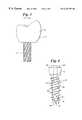
- FIG. 4is a side view, partially in section, of one embodiment of the dental implant in accordance with the present invention.
- FIG. 5is an enlarged sectional view of the thread configuration of the implant of the embodiment shown in FIG. 4 .
- FIG. 6is an elevational bottom view from the distal end of the dental implant of FIG. 4 .
- FIG. 7is an elevational top view from the proximal or head end of the dental implant of FIG. 4 .
- FIG. 8is a side view, partially in section, of a second embodiment of the dental implant in accordance with the present invention.
- FIG. 9is an enlarged view of the thread configuration of the embodiment of the dental implant as shown in FIG. 8 .
- FIG. 10is an elevational bottom view from the distal end of the dental implant of FIG. 8 .
- FIG. 11is an elevational top view from the proximal or head end of the dental implant of FIG. 8 .
- FIG. 12is a side view, partially in section, of a third embodiment similar to that of FIG. 8, but with a modified thread design.
- FIG. 13is a side view, partially in section, of a fourth embodiment of the dental implant of the present invention, which view is similar to that of FIG. 8, but with a further modified thread design.
- FIG. 14is an enlarged view of the thread pattern of the dental implant embodiment of FIG. 13 .
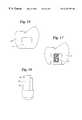
- FIG. 15is an elevational side view, partially in section, of a replacement tooth for use with the implants of FIGS. 8, 12 and 13 .
- FIG. 16is a modified prosthesis receiving post for the embodiments of FIGS. 8, 12 and 13 .
- FIG. 17is a modified replacement tooth for use with the prosthesis receiving post design of FIG. 16 .
- a dental implantprovides support for a replacement tooth or other prosthesis and thus is anchored into a tooth root, bone or other tissue.
- the dental implantprovides support for such replacement tooth or prosthesis at its proximal or superior end.
- a dental implantdoes not function to secure two or more pieces of tissue, bones or other elements together as in conventional bone screws, nor does it function to provide any significant resistance to pulling out force as in conventional tissue or bone screws.
- FIG. 1illustrates a conventional dental implant 10 having a main body portion 11 , a proximal or superior end 12 and a distal or inferior end 14 .
- the proximal end 12is provided with a conventional hex configuration 15 to enable the implant to be rotated and installed into a pre-drilled hole in a tooth root or bone.
- the dental implant of FIG. 1is provided with a hollow interior 16 which extends from the proximal end 12 into the main portion 11 of the implant for a substantial distance toward the distal end 14 .
- This hollow interior 16is provided with internal threads.
- the exterior of the implant 10is provided with threads 18 for securement to a tooth structure.
- Conventional dental implantshave a core to thread ratio greater than 0.70 with the standard being about 0.75 or greater. This translates into a thread to core ratio of less than about 1.40, with the standard being about 1.20 or less.
- the core to thread ratiois the ratio between the dimension at the innermost edge of the thread (the minor diameter) to the dimension at the outermost edge of the thread, while the thread to core ratio is the ratio of the major diameter to the minor diameter.
- FIGS. 2 and 3illustrate elements designed for use with the conventional dental implant of FIG. 1 .
- FIG. 2illustrates a healing screw 17 having a proximal or head end 20 and an elongated stem portion 19 extending from the head 20 toward a distal end.
- the stem portion 19is provided with external threads designed to be received by the internal threads of the hollow interior 16 (FIG. 1) and is substantially smaller in diameter than the proximal end 20 .
- the healing cap 17is conventionally screwed into the hollow interior 16 of the implant 10 after installation of the implant and during the healing period for the surrounding bone or tooth tissue.
- FIG. 3illustrates a conventional replacement tooth 21 having an elongated externally threaded stem 22 at its distal end and a replacement tooth portion 24 at its proximal end.
- the external threads of the stem 22are designed to mate with the internal threads of the interior portion 16 .
- the replacement tooth 21is installed into the implant 10 of FIG. 1 after the necessary healing period has elapsed and the healing cap 17 (FIG. 2) has been removed.
- FIGS. 4-7showing a first embodiment of a dental implant 25 in accordance with the present invention.
- the dental implant 25includes a main body portion 26 with a proximal or superior end 28 and a distal or inferior end 29 .
- the distal end 29is provided with a plurality of cutting edges 32 to provide the implant with self tapping capabilities.
- the cutting edges 32 or other self-tapping structures as applied to dental implantsare well known in the art and such structures are incorporated herein by reference.
- the distal end 29 of the implant 25is also provided with a through-hole 34 for later bone growth, if desired. Such hole 34 , however, is not necessary to achieve the other benefits of the implant 25 .
- the proximal end 28is provided with a rotation head in the form of a hex end or portion 30 for engagement by a hand piece or other tool or adaptor for the purpose of rotating the implant 25 during installation.
- a hollow interior 31extends from the proximal end 28 into the main portion 26 of the implant 25 for a substantial distance toward the distal end 29 .
- the hollow interior 31is provided with internal threads to receive a conventional healing cap or replacement tooth such as as shown in FIGS. 2 and 3, respectively, or any other prosthesis or attachment intended for use with dental implants.
- the diameter of the hollow interior 31is reduced relative to that of conventional implants to accommodate the reduced core to thread ratio.
- the exterior of the main body of the implant 25 as shown in FIG. 4is provided with a plurality of external threads comprising a first series of helical threads 35 extending from the distal end 29 substantially to the proximal end 28 and a second series of helical threads 36 interleaved between the first series of helical threads 35 and also extending from the distal end 29 substantially to the proximal end 28 .
- the helical threads 35 and 36have first and second outer diametrical dimensions which are different from one another. As shown generally in FIG. 4 and more specifically in FIG. 5, the outer or major diameter of the first series of helical threads 35 is greater than the outer or major diameter of the second series of helical threads 36 .
- each of the first series of helical threads 35includes an outer edge 38 extending helically around the implant 25 and defining the thread diameter or major diameter of the threads 35 .
- the specific size of this outer or major diameterwhich is twice the radius “R 01 ” shown in FIG. 5 as the distance between the edge 38 and the implant centerline 33 , will depend of the particular size of the implant.
- Conventional implantsnormally include implants with diameters of 3 mm to 6 mm, with most standard implants being 4 mm or 5 mm. Implants are conventionally provided in lengths from 10 mm to 15 mm and specifically in lengths of 10 mm, 11.5 mm, 13 mm and 15 mm.
- the helical threads 35also include an inner edge 39 .
- the inner edge 39defines the core diameter or minor diameter of the thread 35 which, as shown in FIG. 5, is twice the distance “R i ” between the edge 39 and the centerline 33 .
- the core diameter 39defines the innermost portion of the thread 35 .
- the inner edge 39 of the threadextends helically around the implant 25 .
- the core to thread ratio or the minor to major diameter ratio of thread 35is determined by comparing the minor diameter defined by twice the distance “R i ” to the major diameter defined by twice the distance “R 01 ”.
- this ratio R i /R 01is about 0.70 or less and more preferably about 0.60 or less.
- the range of core to thread ratios for implants in accordance with the present inventionis preferably 0.40 to 0.70, more preferably 0.45 to 0.65 and most preferably 0.50 to 0.60. These ratios are based on a major diameter of 4 mm and a minor diameter of about 2.25 mm for a 4 mm implant, and a major diameter of 5 mm and a minor diameter of about 3 mm for a 5 mm implant.
- the outer edge 38terminates in a flat surface generally parallel to the longitudinal axis of the implant as shown. Although it can, if desired, terminate substantially at a point, it is preferred that the outer edge 38 terminate in a flat portion as shown having a dimension “A 1 ” of less than about 0.2 mm and more preferably between about 0.03 and 0.15 mm.
- the particular height H 1 of the thread 35 defined by the distance between the outer edge 38 and the inner edge 39will vary with the particular size of the implant, the amount of torque desired to install the implant and the compressive force resistance desired.
- the thread 35also includes a pair of side surfaces extending helically from the distal end 29 of the implant to the proximal end 28 .
- These side surfacesinclude a distal or distal facing surface 40 and a proximal or proximal facing surface 41 .
- these surfaces 40 and 41form angles DA 1 and PA 1 , respectively, with a line extending perpendicular to the longitudinal or center axis 33 of the implant.
- these two angles DA 1 and PA 1can be the same, it is preferred that the angle DA 1 be smaller than the angle PA 1 (or that the angle PA 1 be larger than the angle DA 1 ).
- the angle DA 1be less than about 45°, more preferably less than about 25°, and most preferably less than about 10°.
- the angle PA 1be between about 45 and 5°, more preferably between about 40 and 10°, and most preferably between about 35 and 20°.
- the surface 40which comprises the flatter surface or smaller angle face the distal end of the implant as shown.
- the thread design 36is similar to that of the thread 35 except that its outer or major diameter defined by twice the distance “R 02 ” between the outer edge 42 and the centerline 33 is less than the major diameter of the thread 35 . Similar to the thread 35 , the inner dimension of the thread 36 is defined by the inner edge 39 .
- the core to thread ratio, or minor to major diameter ratio, of the thread 36is defined as the ratio of its minor diameter (twice the distance “R i ”) to its major diameter (twice the distance “R 02 ”). This core to thread ratio is expected to be greater than the core to thread ratio of the thread 35 since the denominator of the ratio is less. However, even this ratio is preferably less than the standard ratio of about 0.75. It is contemplated, however, that the core to thread ratio of the smaller thread in a thread pattern of multiple thread diameters could be greater than the standard core to thread ratio of 0.75 without deviating from the present invention.
- the major diameter of the largest threadis used.
- the preferred values of the core to thread ratio as set forth above with respect to the thread 35 (the largest thread)are applicable.
- the outer edge 42 of the thread 36is provided with a flat portion extending helically around the implant. Although this outer portion 42 can terminate at a point, it preferably terminates at a flat portion with a dimension A 2 of less than about 0.1 mm and more preferably between about 0.3 and 0.1 mm.
- the second helical thread 36includes a pair of sides extending helically along the length of the implant. Specifically, these sides include a distal or distal facing side 44 and a proximal or proximal facing side 45 . These sides 44 and 45 form angles DA 2 and PA 2 with a line extending perpendicular to the longitudinal or center axis 33 of the implant, respectively. Although these angles can be the same, it is preferred for the angle DA 2 of the distal side 44 to be smaller than the angle PA 2 of the proximal side 45 (or the angle PA 2 to be larger than the angle DA 2 ).
- the angle DA 2 of the distal side 44is less than 45°, more preferably less than about 25° and most preferably less than about 10°.
- the angle PA 2 of the proximal side 45is preferably between about 45 and 5°, and more preferably between about 35 and 10°.
- the distance between the threads 35 and 36 measured from the top outer edge of the thread 35 to the top outer edge of the thread 36is defined by the distance W 1
- the distance between the threads 36 and 35 measured from the top outer edge of the thread 36 to the top outer edge of the thread 35is defined by the distance W 2 .
- These distancesrelate to the pitch of the threads or the number of threads per unit length.
- the distances W 1 , and W 2are such as to provide a pitch for the threads 35 of about 8-20 threads per inch and a similar pitch for the threads 36 of about 8-20 threads per inch. More preferably, the thread pitch should result in 10-18 threads per inch and most preferably about 12 threads per inch.
- the pitch of the threads 35 and 36is preferably constant throughout the length of the implant, the pitch can be designed to vary, if desired.
- a 13 mm implanthas about 4 to 10 turns of the thread 35 . More preferably, a 13 mm implant has about 6 to 8 turns of the thread 35 . This translates to a thread 35 density pitch of about 12 to 16 threads per inch.
- the implant of the present inventioncan be of various lengths, it is preferably of a length that will penetrate the cortical plate, but preferably not go through it.
- the preferred implant length in accordance with the present inventionis less than 20 mm. More preferably, the length is no greater than 15 mm, and most preferably the length is about 10 to 15 mm.
- the length of the implantis that portion comprised of the threads.
- FIGS. 8, 9 , 10 and 11illustrating a second embodiment of a dental implant 47 of the present invention.
- the embodiment of the FIG. 8includes a main implant portion 46 having first and second helical threads 50 and 51 , respectively, extending from the distal end 48 toward the proximal end 49 .
- the main body portion 46 and threads 50 and 51 of the embodiment of FIG. 8are substantially the same as that of the embodiment of FIG. 4 .
- the elevational distal end view of FIG. 10 of the embodiment of FIG. 8is substantially the same as the distal end view of FIG. 6 .
- the enlarged thread configuration illustrated in FIG. 9is also similar to that shown in FIG. 5 with respect to the embodiment of FIG. 4 .
- first and second helical threads 50 and 51 of the embodiment of FIG. 8extend helically along a substantial length of the implant and are interleaved between each other.
- the core to thread ratios of the threads 50 and 51 and their respective configurations and dimensionsare similar to those described and shown above with respect to FIG. 5 .
- each of the threads 50 and 51include distal or distal facing sides 55 and 58 , respectively, and proximal or proximal facing sides 56 and 59 , respectively. The angles which these sides form with a line extending perpendicular to the longitudinal axis or center line of the implant is similar to that disclosed with reference to FIG. 5 .
- FIG. 8differs from that of FIG. 4 in that an extended neck 43 is provided between the threaded portion and the proximal end 49 , a head or prosthesis receiving post 52 is provided to the proximal end 49 of the implant and the hollowed out interior portion 31 of the embodiment of FIG. 4 is eliminated.
- the proximal end of the head or post 52is provided with a structure 54 for rotating the implant 47 during installation.
- this structure 54comprises a pair of flats on opposite sides of the post 52 .
- the structure 54is designed to mate with a hand piece or other tool or adaptor.
- this structurecan be any structure which enables the implant to be rotated. It is also contemplated that a portion of the head or post 52 can be provided with a conventional hex end to receive an appropriate tool for rotation.
- the head 52includes a circumferential groove 53 near its upper end. This groove is intended to receive a rubber loop to assist in installation of the implant. A plurality of grooves 57 are also provided for use when constructing impressions or temporaries.
- a replacement tooth or other prosthesissuch as that illustrated in FIG. 15 would be connected to the post 52 .
- the replacement toothincludes a conventional tooth exterior 60 and an interior conforming substantially to the exterior figuration of the post 52 and portion 54 of FIG. 8 .
- the replacement tooth of FIG. 15would be secured to the post 52 through an appropriate adhesive.
- the neck 43can be of varying heights depending on the nature of the tissue and the particular prosthesis used. Preferably, the height of the neck 43 is between about 0.5 and 8 mm and most preferably between about 1 and 5 mm.
- FIG. 12is an embodiment similar to that of FIG. 8 except that the threads 64 of the implant of FIG. 12 are of the same diameter and are symmetrical.
- the core to thread ratio of the threads 64are substantially the same as that of the embodiment of FIG. 4 .
- the core to thread ratiosare preferably 0.70 or less and more preferably 0.60 or less.
- the preferred ranges of such ratiosare 0.40 to 0.70, with more preferred and most preferred ratios being 0.45 to 0.65 and 0.50 to 0.60, respectively.
- FIG. 12also includes a modified prosthesis receiving post comprising the post 63 extending outwardly from the neck 43 and a hexagonal end 54 to facilitate rotation of the implant.
- FIG. 13is similar to that of the embodiment of FIG. 12 in that the threads 66 are of equal outer diameter, but is dissimilar to that of FIG. 12 in that the threads are not symmetrical.
- the details of this thread configurationare shown in FIG. 14 .
- the distal or distal facing side 68 of the threads 66forms an angle DA 3 with a line perpendicular to the longitudinal axis or center line 33 of the implant, while the proximal or proximal facing side 69 of the threads 66 forms an angle PA 3 .
- the angle DA 3is less than the angle PA 3 (or the angle PA 3 is greater than the angle DA 3 ), with the preferred values of those angles being similar to those described above with respect to FIG. 5 .
- FIG. 16illustrates an alternate prosthesis receiving post for the implant embodiments of FIGS. 8, 12 and 13 .
- the head or post portion 52is provided with an internal recess 70 .
- This recess 70is provided with internal threads which are intended to receive external threads from a replacement tooth such as that illustrated in FIG. 17 .
- the replacement toothincludes a main replacement tooth portion 71 and an elongated stem portion 72 having external threads matching the internal threads of the internal portion 70 of FIG. 16 .
- the stem portion 72is positioned entirely within the tooth portion 71 .
- the stem 72is positioned into the interior portion 70 and rotated until tight.
- a dental implantwhich includes a proximal end, a distal end and an externally threaded shaft.
- the shaftpreferably includes a core to thread ratio as specified above.
- the shaftfurther includes first and second helical threads which are interleaved with one another and embody first and second thread diameters, with one of the thread diameters being different than the other.
- the implantalso preferably includes a prosthesis receiving post integrally positioned at the proximal end of the implant and extending outwardly from the proximal end to receive a prosthesis.
- the methodfurther includes drilling or boring a hole into a tooth root or bone at a desired location and then inserting the distal end of the implant into the hole and rotating the dental implant to a desired degree of installation.
- the implantis not installed through the cortical plate.
- a replacement tooth or other prosthesisis mounted or attached to the prosthesis receiving post either via a threaded connection, adhesives, or the like. This installation of the replacement tooth or prosthesis is preferably performed immediately.
- the preferred methodis a single surgery method in which both the installation of the implant and the installation of the prosthesis are completed in a single office visit.
Landscapes
- Health & Medical Sciences (AREA)
- Life Sciences & Earth Sciences (AREA)
- Chemical & Material Sciences (AREA)
- Food Science & Technology (AREA)
- Engineering & Computer Science (AREA)
- Epidemiology (AREA)
- Animal Behavior & Ethology (AREA)
- General Health & Medical Sciences (AREA)
- Public Health (AREA)
- Veterinary Medicine (AREA)
- Dentistry (AREA)
- Orthopedic Medicine & Surgery (AREA)
- Oral & Maxillofacial Surgery (AREA)
- Polymers & Plastics (AREA)
- Oil, Petroleum & Natural Gas (AREA)
- Molecular Biology (AREA)
- Dental Prosthetics (AREA)
- Prostheses (AREA)
Abstract
Description
Claims (19)
Priority Applications (2)
| Application Number | Priority Date | Filing Date | Title |
|---|---|---|---|
| US09/416,355US6234797B1 (en) | 1998-10-19 | 1999-10-12 | Dental implant and method for installing the same |
| US09/861,874US20010055744A1 (en) | 1998-10-19 | 2001-05-21 | Dental implant and method for installing the same |
Applications Claiming Priority (2)
| Application Number | Priority Date | Filing Date | Title |
|---|---|---|---|
| US09/175,007US5967783A (en) | 1998-10-19 | 1998-10-19 | Threaded dental implant with a core to thread ratio facilitating immediate loading and method of installation |
| US09/416,355US6234797B1 (en) | 1998-10-19 | 1999-10-12 | Dental implant and method for installing the same |
Related Parent Applications (1)
| Application Number | Title | Priority Date | Filing Date |
|---|---|---|---|
| US09/175,007Continuation-In-PartUS5967783A (en) | 1998-10-16 | 1998-10-19 | Threaded dental implant with a core to thread ratio facilitating immediate loading and method of installation |
Related Child Applications (1)
| Application Number | Title | Priority Date | Filing Date |
|---|---|---|---|
| US09/861,874ContinuationUS20010055744A1 (en) | 1998-10-19 | 2001-05-21 | Dental implant and method for installing the same |
Publications (1)
| Publication Number | Publication Date |
|---|---|
| US6234797B1true US6234797B1 (en) | 2001-05-22 |
Family
ID=22638451
Family Applications (3)
| Application Number | Title | Priority Date | Filing Date |
|---|---|---|---|
| US09/175,007Expired - Fee RelatedUS5967783A (en) | 1998-10-16 | 1998-10-19 | Threaded dental implant with a core to thread ratio facilitating immediate loading and method of installation |
| US09/416,355Expired - Fee RelatedUS6234797B1 (en) | 1998-10-19 | 1999-10-12 | Dental implant and method for installing the same |
| US09/861,874AbandonedUS20010055744A1 (en) | 1998-10-19 | 2001-05-21 | Dental implant and method for installing the same |
Family Applications Before (1)
| Application Number | Title | Priority Date | Filing Date |
|---|---|---|---|
| US09/175,007Expired - Fee RelatedUS5967783A (en) | 1998-10-16 | 1998-10-19 | Threaded dental implant with a core to thread ratio facilitating immediate loading and method of installation |
Family Applications After (1)
| Application Number | Title | Priority Date | Filing Date |
|---|---|---|---|
| US09/861,874AbandonedUS20010055744A1 (en) | 1998-10-19 | 2001-05-21 | Dental implant and method for installing the same |
Country Status (6)
| Country | Link |
|---|---|
| US (3) | US5967783A (en) |
| EP (1) | EP1126793A1 (en) |
| JP (1) | JP2002527188A (en) |
| AU (1) | AU1122500A (en) |
| CA (1) | CA2349571A1 (en) |
| WO (1) | WO2000023003A1 (en) |
Cited By (26)
| Publication number | Priority date | Publication date | Assignee | Title |
|---|---|---|---|---|
| US6431869B1 (en)* | 1996-01-18 | 2002-08-13 | Implant Innovations, Inc. | Reduced friction screw-type dental implant |
| US20030124489A1 (en)* | 2001-06-04 | 2003-07-03 | Hurson Steven M. | Natural implant system |
| US20040121289A1 (en)* | 2002-12-23 | 2004-06-24 | Miller Robert Jeffrey | Dental implant |
| US20040161725A1 (en)* | 2003-02-13 | 2004-08-19 | Clement Milton A. | Dental implantation system, support, and related methods |
| US20050147943A1 (en)* | 2004-01-06 | 2005-07-07 | Sang-Kohn Chang | Dental implant fixture |
| US20060199152A1 (en)* | 2001-06-04 | 2006-09-07 | Hurson Steven M | Natural implant system |
| US7137817B2 (en)* | 2000-12-22 | 2006-11-21 | Quantum Bioengineering, Ltd. | Implant fixation device |
| US20080057472A1 (en)* | 2006-08-30 | 2008-03-06 | Clement Milton A | Dental fixture implantation system and associated method |
| US20080147119A1 (en)* | 2006-11-01 | 2008-06-19 | Depuy Mitek, Inc. | Wired sutures |
| US20080234763A1 (en)* | 2007-03-16 | 2008-09-25 | Patterson Chad J | Surgical compression bone screw |
| US20090076544A1 (en)* | 2007-09-14 | 2009-03-19 | Depuy Mitek, Inc. | Dual thread cannulated suture anchor |
| WO2010021478A3 (en)* | 2008-08-20 | 2010-06-10 | 주식회사 메가젠임플란트 | Dental implant fixture |
| US20100240010A1 (en)* | 2009-03-23 | 2010-09-23 | Holmstroem Johan | Fixture |
| US20100304335A1 (en)* | 2007-12-07 | 2010-12-02 | Juan Carlos Garcia Saban | Post-extraction dental implant |
| US20110143318A1 (en)* | 2009-12-11 | 2011-06-16 | Zvi Laster | Winged implant |
| US8435264B2 (en) | 2010-08-30 | 2013-05-07 | Depuy Mitek, Llc | Knotless suture anchor and driver |
| US8460340B2 (en) | 2010-08-30 | 2013-06-11 | Depuy Mitek, Llc | Knotless suture anchor |
| US8469998B2 (en) | 2010-08-30 | 2013-06-25 | Depuy Mitek, Llc | Knotless suture anchor |
| US20140004481A1 (en)* | 2010-12-20 | 2014-01-02 | Frank-Peter Spahn | Crestal Implant And Method For Processing Same |
| US8702754B2 (en) | 2007-09-14 | 2014-04-22 | Depuy Mitek, Llc | Methods for anchoring suture to bone |
| US20140141388A1 (en)* | 2012-08-07 | 2014-05-22 | Mazen Dukhan | Dental Implant and Method of Implantation |
| CN104997566A (en)* | 2014-04-17 | 2015-10-28 | 萨摩亚商星世代股份有限公司台湾分公司 | Dental implant special for paranasal sinus |
| CN105012025A (en)* | 2014-04-17 | 2015-11-04 | 萨摩亚商星世代股份有限公司台湾分公司 | Universal rotary push structure for multi-size dental implants |
| US10188489B2 (en) | 2014-04-17 | 2019-01-29 | Star Generation Limited Taiwan Branch | Sinus implant |
| AU2014202173B2 (en)* | 2014-04-19 | 2020-02-06 | Star Generation Limited Taiwan Branch | Implant having a bone growth powder/biomedical filler rotary push structure |
| US11786343B2 (en) | 2020-07-09 | 2023-10-17 | Southern Implants (Pty) Ltd | Dental implants with stepped threads and systems and methods for making the same |
Families Citing this family (99)
| Publication number | Priority date | Publication date | Assignee | Title |
|---|---|---|---|---|
| US6149432A (en)* | 1993-12-27 | 2000-11-21 | Biolok International, Inc. | Buttress thread dental implant |
| US5967783A (en) | 1998-10-19 | 1999-10-19 | Ura; Robert S. | Threaded dental implant with a core to thread ratio facilitating immediate loading and method of installation |
| US6244073B1 (en)* | 1999-02-05 | 2001-06-12 | Dennis John Kaping, Jr. | Body jewelry cap |
| US6743233B1 (en) | 2000-08-02 | 2004-06-01 | Orthopaedic Biosystems, Ltd., Inc. | Medical screw and method of installation |
| US20060078847A1 (en)* | 2000-09-29 | 2006-04-13 | Kwan Norman H | Dental implant system and additional methods of attachment |
| US20070037123A1 (en)* | 2000-10-26 | 2007-02-15 | Mansueto Robert F | High-strength dental-implant w/curvilinear-indexing and tool-free delivery-system |
| KR100414885B1 (en)* | 2000-12-09 | 2004-01-24 | 주식회사 워랜텍 | Dental implant and head of a compaction drill |
| US6368108B1 (en) | 2001-01-05 | 2002-04-09 | Sulzer Dental Inc | Method for immediately placing a non-occlusive dental implant prosthesis |
| US6746244B2 (en)* | 2001-01-05 | 2004-06-08 | Sulzer Dental Inc. | Method for immediately placing a non-occlusive dental implant prosthesis |
| US6402515B1 (en)* | 2001-01-10 | 2002-06-11 | Sulzer Dental Inc. | Dental implant with variable profile thread |
| WO2002062255A1 (en)* | 2001-02-02 | 2002-08-15 | Friadent Gmbh | Implant system |
| US6672870B2 (en) | 2001-03-20 | 2004-01-06 | John G. Knapp | Method and instrumentation for attaching dentures |
| GB0123804D0 (en)* | 2001-10-04 | 2001-11-21 | Osseobiotek Ltd | Implant |
| DE10159683A1 (en) | 2001-11-30 | 2003-06-18 | Michael Gahlert | Dantalimplantat |
| SE523395C2 (en) | 2001-12-21 | 2004-04-13 | Nobel Biocare Ab | Implants and methods and systems for providing such implants |
| SE520756C2 (en)* | 2001-12-21 | 2003-08-19 | Nobel Biocare Ab | Method of providing surface structure on implants as well as such implants |
| US7091267B2 (en)* | 2002-03-19 | 2006-08-15 | General Electric Company | Resinous compositions, method of manufacture thereof and articles fabricated from the composition |
| JP2005528183A (en)* | 2002-06-06 | 2005-09-22 | ノーベル ビウカーレ アーベー | Natural implant system |
| US7033174B2 (en)* | 2002-06-07 | 2006-04-25 | Thierry Giorno | Prosthetic mounting device |
| US7217130B2 (en)* | 2002-06-07 | 2007-05-15 | Thierry Giorno | Prosthesis mounting device and assembly |
| US6793678B2 (en) | 2002-06-27 | 2004-09-21 | Depuy Acromed, Inc. | Prosthetic intervertebral motion disc having dampening |
| ES2211292B1 (en)* | 2002-07-10 | 2005-04-01 | Implant Microdent System, S.L. | DENTAL IMPLANT, PERFECTED. |
| IL166627A0 (en)* | 2002-08-02 | 2006-01-15 | Yissum Res Dev Co | Treatment of multiple sclerosis with brain targeted anti-oxidant compounds |
| IL151145A0 (en)* | 2002-08-08 | 2003-04-10 | Aminov Baruch | Apparatus for performing dental implants |
| SE526667C2 (en)* | 2002-12-30 | 2005-10-25 | Nobel Biocare Ab | Device for implants and method for making the implant |
| EP1444963B1 (en)* | 2003-02-05 | 2006-12-06 | Straumann Holding AG | Extension piece for a dental implant, transmission aid, and method for preparing a base for a retention piece |
| US7179088B2 (en)* | 2003-03-18 | 2007-02-20 | Cagenix, Inc. | Lobed dental implant |
| US20040185418A1 (en)* | 2003-03-18 | 2004-09-23 | Schulter Carl W. | Dental implant fixture |
| KR100487132B1 (en)* | 2003-03-26 | 2005-05-03 | 설영택 | Helical implant |
| DE10319036A1 (en)* | 2003-04-25 | 2004-11-25 | Volz, Ulrich, Dr.med.dent. | dental implant |
| IL156033A0 (en) | 2003-05-21 | 2004-03-28 | Ophir Fromovich Ophir Fromovic | Dental implant |
| US7670142B2 (en)* | 2003-06-03 | 2010-03-02 | Intra-Lock International, Inc. | Prosthesis mounting device and assembly |
| US20050021036A1 (en)* | 2003-07-21 | 2005-01-27 | Whitmore Robin C. | Self-drilling, self-tapping bone screw |
| US8540755B2 (en)* | 2003-07-21 | 2013-09-24 | Robin C. Whitmore | Self-drilling self-tapping bone screw |
| US7108511B1 (en)* | 2003-08-15 | 2006-09-19 | Shatkin Todd E | System of dental restoration of single stage dental implants and loading with a preformed crown restoration |
| KR20050022738A (en)* | 2003-08-29 | 2005-03-08 | 주식회사 메가젠 | Dental implant |
| SE526746C2 (en)* | 2003-12-11 | 2005-11-01 | Nobel Biocare Ab | Implant applicable to dentures with associated soft tissue |
| GB0405655D0 (en)* | 2004-03-12 | 2004-04-21 | Eilertsen Eilert | Dental implant |
| US9387313B2 (en) | 2004-08-03 | 2016-07-12 | Interventional Spine, Inc. | Telescopic percutaneous tissue dilation systems and related methods |
| US20060154203A1 (en)* | 2005-01-10 | 2006-07-13 | Emanuelli Silvio F | Dental implants having anatomical emergence |
| US7699613B2 (en)* | 2005-02-11 | 2010-04-20 | Niznick Gerald A | One-piece, screw-receiving, externally-threaded endosseous dental implants and related transfer components, comfort caps and abutments |
| DE202005005421U1 (en)* | 2005-04-05 | 2006-08-10 | Dinkelacker, Wolfgang, Dr.med.dent. | Helical dental implant |
| EP1792580A1 (en)* | 2005-09-27 | 2007-06-06 | Ziterion GmbH | Two-part dental implants made of biocompatible ceramics |
| CA2627248A1 (en)* | 2005-11-18 | 2007-05-24 | Apexum Ltd. | Ablating apparatus particularly useful for removal of dental periapical lesions |
| ES2363527T3 (en)* | 2006-10-11 | 2011-08-08 | Astra Tech Ab | IMPLANT. |
| WO2008070863A2 (en) | 2006-12-07 | 2008-06-12 | Interventional Spine, Inc. | Intervertebral implant |
| ES2285955B1 (en)* | 2007-02-16 | 2009-02-01 | Marcela Ridao Dalmau | "DENTAL IMPLANT". |
| US7806693B2 (en) | 2007-04-23 | 2010-10-05 | Nobel Biocare Services Ag | Dental implant |
| US8038442B2 (en) | 2007-04-23 | 2011-10-18 | Nobel Biocare Services Ag | Dental implant and dental component connection |
| US8900307B2 (en) | 2007-06-26 | 2014-12-02 | DePuy Synthes Products, LLC | Highly lordosed fusion cage |
| US8221119B1 (en) | 2007-10-09 | 2012-07-17 | Maurice Valen | Dental implant and method of installing the same |
| ES2321051B1 (en)* | 2007-11-30 | 2010-03-04 | Juan Carlos Garcia Saban | DENTAL IMPLANT. |
| EP2237748B1 (en) | 2008-01-17 | 2012-09-05 | Synthes GmbH | An expandable intervertebral implant |
| US8936641B2 (en) | 2008-04-05 | 2015-01-20 | DePuy Synthes Products, LLC | Expandable intervertebral implant |
| US8758012B2 (en)* | 2008-07-14 | 2014-06-24 | Nobel Biocare Services Ag | Compact dental implant |
| US8454363B2 (en) | 2008-11-06 | 2013-06-04 | William B. Worthington | Dental implant system |
| KR101029065B1 (en)* | 2009-02-24 | 2011-04-15 | (주) 시원 | Dental implant |
| US9526620B2 (en) | 2009-03-30 | 2016-12-27 | DePuy Synthes Products, Inc. | Zero profile spinal fusion cage |
| IL201902A (en) | 2009-11-03 | 2012-12-31 | Ben-Zion Karmon | Dental implant |
| US9393129B2 (en) | 2009-12-10 | 2016-07-19 | DePuy Synthes Products, Inc. | Bellows-like expandable interbody fusion cage |
| KR101134342B1 (en) | 2010-04-22 | 2012-04-09 | 주식회사 메가젠임플란트 | Dental implant fixture and implant set having the same |
| US8979860B2 (en) | 2010-06-24 | 2015-03-17 | DePuy Synthes Products. LLC | Enhanced cage insertion device |
| US9907560B2 (en) | 2010-06-24 | 2018-03-06 | DePuy Synthes Products, Inc. | Flexible vertebral body shavers |
| US8623091B2 (en) | 2010-06-29 | 2014-01-07 | DePuy Synthes Products, LLC | Distractible intervertebral implant |
| US9402732B2 (en) | 2010-10-11 | 2016-08-02 | DePuy Synthes Products, Inc. | Expandable interspinous process spacer implant |
| JP5108117B2 (en)* | 2011-01-04 | 2012-12-26 | ノベル バイオケア サーヴィシィズ アクチエンゲゼルシャフト | Natural implant system |
| EP3725260B1 (en) | 2011-01-13 | 2023-06-07 | Align Technology, Inc. | Method and system for creating a virtual dental model |
| EP2877127B1 (en) | 2012-07-26 | 2019-08-21 | Synthes GmbH | Expandable implant |
| US20140067069A1 (en) | 2012-08-30 | 2014-03-06 | Interventional Spine, Inc. | Artificial disc |
| US9782209B2 (en)* | 2012-10-03 | 2017-10-10 | Rtg Scientific | Medical fastener |
| US9717601B2 (en) | 2013-02-28 | 2017-08-01 | DePuy Synthes Products, Inc. | Expandable intervertebral implant, system, kit and method |
| US9522070B2 (en) | 2013-03-07 | 2016-12-20 | Interventional Spine, Inc. | Intervertebral implant |
| USD816841S1 (en) | 2014-12-15 | 2018-05-01 | Jjgc Industria E Comercio De Materiais Dentarios S/A | Bone implant |
| BR102014031426B1 (en) | 2014-12-15 | 2018-07-24 | Jjgc Ind E Comercio De Materiais Dentarios S/A | implant |
| US10413387B2 (en) | 2015-01-20 | 2019-09-17 | John Andler | Threaded dental implant |
| US11426290B2 (en) | 2015-03-06 | 2022-08-30 | DePuy Synthes Products, Inc. | Expandable intervertebral implant, system, kit and method |
| US9913727B2 (en) | 2015-07-02 | 2018-03-13 | Medos International Sarl | Expandable implant |
| USD783823S1 (en) | 2016-02-05 | 2017-04-11 | Silvio Franco Emanuelli | Post part for a dental implant |
| USD783824S1 (en) | 2016-02-05 | 2017-04-11 | Silvio Franco Emanuelli | Root part for a dental implant |
| USD783822S1 (en) | 2016-02-05 | 2017-04-11 | Silvio Franco Emanuelli | Root part for a dental implant |
| USD783825S1 (en) | 2016-02-05 | 2017-04-11 | Silvio Franco Emanuelli | Post part for a dental implant |
| USD785179S1 (en) | 2016-02-05 | 2017-04-25 | Silvio Franco Emanuelli | Post part for a dental implant |
| USD783826S1 (en) | 2016-02-05 | 2017-04-11 | Silvio Franco Emanuelli | Root part for a dental implant |
| BR102016010184B1 (en) | 2016-05-05 | 2020-10-27 | Jjgc Indústria E Comércio De Materiais Dentários S.A. | prosthetic set and process for producing the same |
| US11510788B2 (en) | 2016-06-28 | 2022-11-29 | Eit Emerging Implant Technologies Gmbh | Expandable, angularly adjustable intervertebral cages |
| EP3474784A2 (en) | 2016-06-28 | 2019-05-01 | Eit Emerging Implant Technologies GmbH | Expandable and angularly adjustable intervertebral cages with articulating joint |
| US10537436B2 (en) | 2016-11-01 | 2020-01-21 | DePuy Synthes Products, Inc. | Curved expandable cage |
| US10888433B2 (en) | 2016-12-14 | 2021-01-12 | DePuy Synthes Products, Inc. | Intervertebral implant inserter and related methods |
| US10398563B2 (en) | 2017-05-08 | 2019-09-03 | Medos International Sarl | Expandable cage |
| US11344424B2 (en) | 2017-06-14 | 2022-05-31 | Medos International Sarl | Expandable intervertebral implant and related methods |
| US10940016B2 (en) | 2017-07-05 | 2021-03-09 | Medos International Sarl | Expandable intervertebral fusion cage |
| IL254999B2 (en)* | 2017-10-15 | 2024-05-01 | Ben Zion Karmon | Improved dental implant |
| DE102018102568A1 (en) | 2018-02-06 | 2019-08-08 | Karl Leibinger Medizintechnik Gmbh & Co. Kg | Implant with radially extended post to support structure, soft tissue displacement system, manufacturing process and planning process for manufacturing an implant |
| US11446156B2 (en) | 2018-10-25 | 2022-09-20 | Medos International Sarl | Expandable intervertebral implant, inserter instrument, and related methods |
| US11426286B2 (en) | 2020-03-06 | 2022-08-30 | Eit Emerging Implant Technologies Gmbh | Expandable intervertebral implant |
| US11850160B2 (en) | 2021-03-26 | 2023-12-26 | Medos International Sarl | Expandable lordotic intervertebral fusion cage |
| US11752009B2 (en) | 2021-04-06 | 2023-09-12 | Medos International Sarl | Expandable intervertebral fusion cage |
| US12090064B2 (en) | 2022-03-01 | 2024-09-17 | Medos International Sarl | Stabilization members for expandable intervertebral implants, and related systems and methods |
| US20230372067A1 (en)* | 2022-05-20 | 2023-11-23 | Dustin Shin | Dental implant for preserving bone and improving osseointegration |
Citations (27)
| Publication number | Priority date | Publication date | Assignee | Title |
|---|---|---|---|---|
| US3905109A (en)* | 1974-03-22 | 1975-09-16 | Crysta Dent Inc | Dental implant member |
| US4406623A (en) | 1981-01-09 | 1983-09-27 | Grafelmann Hans L | Screw-type bone implant for receiving a dental prosthesis |
| US4842518A (en) | 1986-09-04 | 1989-06-27 | Vent-Plant Corporation | Submergible screw-type dental implant and method of utilization |
| WO1990014801A1 (en) | 1989-06-05 | 1990-12-13 | Pascal Prunier | Process for the manufacture of prosthetic elements, and elements produced thereby |
| US5007835A (en) | 1989-08-17 | 1991-04-16 | Maurice Valen | Dental implant |
| US5015186A (en) | 1987-09-24 | 1991-05-14 | Detsch Steven G | Dental implant attachment system |
| US5052930A (en) | 1989-11-22 | 1991-10-01 | Lodde Jean Pierre | Dental implant and method of implantation |
| US5087201A (en)* | 1987-12-04 | 1992-02-11 | Mondani Luigi P | Self-threading pin for the implantation of dental prosthesis |
| US5088926A (en) | 1990-01-05 | 1992-02-18 | Manfred Lang | Implant for the jawbone |
| US5145371A (en) | 1989-09-15 | 1992-09-08 | Nobelpharma Ab | Distance member |
| US5199873A (en)* | 1990-01-15 | 1993-04-06 | Friedrichsfeld Ag Keramik- Und Kunststoffwerke | Dental implant |
| US5209659A (en) | 1990-09-05 | 1993-05-11 | Impla-Med Incorporated | Method for installing a dental implant |
| US5322443A (en) | 1993-02-11 | 1994-06-21 | Implant Innovations, Inc. | Method and means for affixing a component to a dental implant |
| US5336225A (en) | 1991-05-24 | 1994-08-09 | Orthopaedic Biosystems, Ltd. | Bone fastening device |
| US5338197A (en) | 1993-04-13 | 1994-08-16 | Kwan Norman H K | Dental implant having cutting means |
| US5505736A (en) | 1992-02-14 | 1996-04-09 | American Cyanamid Company | Surgical fastener with selectively coated ridges |
| US5522843A (en) | 1994-02-23 | 1996-06-04 | Orthopaedic Biosystems Limited, Inc. | Apparatus for attaching soft tissue to bone |
| US5527183A (en)* | 1993-08-18 | 1996-06-18 | Collaborative Enterprises, Inc. | Endosseous implant system |
| US5538428A (en) | 1994-04-05 | 1996-07-23 | Attachments International | Packing delivery system for dental implant and method |
| US5544993A (en)* | 1993-12-13 | 1996-08-13 | H+E,Uml A+Ee Rle; Anton | Threaded fastener |
| US5603338A (en) | 1994-11-30 | 1997-02-18 | Innovative Implants, Inc. | Implant surface preparation utilizing acid treatment |
| US5642996A (en) | 1993-10-20 | 1997-07-01 | Nikon Corporation | Endosseous implant |
| US5643269A (en) | 1990-08-24 | 1997-07-01 | Haerle; Anton | Externally threaded bodies for use as taps or screws |
| US5662476A (en) | 1992-06-29 | 1997-09-02 | Nobel Biocare Ab | Prosthetic implant restoration method |
| US5692904A (en) | 1993-02-11 | 1997-12-02 | Implant Innovations, Inc. | Method and means for affixing a component to a dental implant |
| US5743914A (en) | 1996-06-06 | 1998-04-28 | Skiba; Jeffry B. | Bone screw |
| US5967783A (en) | 1998-10-19 | 1999-10-19 | Ura; Robert S. | Threaded dental implant with a core to thread ratio facilitating immediate loading and method of installation |
Family Cites Families (3)
| Publication number | Priority date | Publication date | Assignee | Title |
|---|---|---|---|---|
| US5062800A (en) | 1990-03-21 | 1991-11-05 | Core-Vent Corporation | Dental implant handle, and dental implant package including a dental implant handle |
| US5368160A (en) | 1993-12-21 | 1994-11-29 | Calcitek, Inc. | Sterile packaging for dental implant system |
| US5582299A (en) | 1994-03-01 | 1996-12-10 | Implant Innovations, Inc. | Dental implant packaging |
- 1998
- 1998-10-19USUS09/175,007patent/US5967783A/ennot_activeExpired - Fee Related
- 1999
- 1999-10-12USUS09/416,355patent/US6234797B1/ennot_activeExpired - Fee Related
- 1999-10-19AUAU11225/00Apatent/AU1122500A/ennot_activeAbandoned
- 1999-10-19CACA002349571Apatent/CA2349571A1/ennot_activeAbandoned
- 1999-10-19JPJP2000576781Apatent/JP2002527188A/enactivePending
- 1999-10-19WOPCT/US1999/024364patent/WO2000023003A1/ennot_activeApplication Discontinuation
- 1999-10-19EPEP99955024Apatent/EP1126793A1/ennot_activeWithdrawn
- 2001
- 2001-05-21USUS09/861,874patent/US20010055744A1/ennot_activeAbandoned
Patent Citations (28)
| Publication number | Priority date | Publication date | Assignee | Title |
|---|---|---|---|---|
| US3905109A (en)* | 1974-03-22 | 1975-09-16 | Crysta Dent Inc | Dental implant member |
| US4406623A (en) | 1981-01-09 | 1983-09-27 | Grafelmann Hans L | Screw-type bone implant for receiving a dental prosthesis |
| US4842518A (en) | 1986-09-04 | 1989-06-27 | Vent-Plant Corporation | Submergible screw-type dental implant and method of utilization |
| US5015186A (en) | 1987-09-24 | 1991-05-14 | Detsch Steven G | Dental implant attachment system |
| US5087201A (en)* | 1987-12-04 | 1992-02-11 | Mondani Luigi P | Self-threading pin for the implantation of dental prosthesis |
| WO1990014801A1 (en) | 1989-06-05 | 1990-12-13 | Pascal Prunier | Process for the manufacture of prosthetic elements, and elements produced thereby |
| US5007835A (en) | 1989-08-17 | 1991-04-16 | Maurice Valen | Dental implant |
| US5145371A (en) | 1989-09-15 | 1992-09-08 | Nobelpharma Ab | Distance member |
| US5052930A (en) | 1989-11-22 | 1991-10-01 | Lodde Jean Pierre | Dental implant and method of implantation |
| US5088926A (en) | 1990-01-05 | 1992-02-18 | Manfred Lang | Implant for the jawbone |
| US5199873A (en)* | 1990-01-15 | 1993-04-06 | Friedrichsfeld Ag Keramik- Und Kunststoffwerke | Dental implant |
| US5643269A (en) | 1990-08-24 | 1997-07-01 | Haerle; Anton | Externally threaded bodies for use as taps or screws |
| US5209659A (en) | 1990-09-05 | 1993-05-11 | Impla-Med Incorporated | Method for installing a dental implant |
| US5336225A (en) | 1991-05-24 | 1994-08-09 | Orthopaedic Biosystems, Ltd. | Bone fastening device |
| US5505736A (en) | 1992-02-14 | 1996-04-09 | American Cyanamid Company | Surgical fastener with selectively coated ridges |
| US5662476A (en) | 1992-06-29 | 1997-09-02 | Nobel Biocare Ab | Prosthetic implant restoration method |
| US5322443A (en) | 1993-02-11 | 1994-06-21 | Implant Innovations, Inc. | Method and means for affixing a component to a dental implant |
| US5692904A (en) | 1993-02-11 | 1997-12-02 | Implant Innovations, Inc. | Method and means for affixing a component to a dental implant |
| US5338197A (en) | 1993-04-13 | 1994-08-16 | Kwan Norman H K | Dental implant having cutting means |
| US5527183A (en)* | 1993-08-18 | 1996-06-18 | Collaborative Enterprises, Inc. | Endosseous implant system |
| US5642996A (en) | 1993-10-20 | 1997-07-01 | Nikon Corporation | Endosseous implant |
| US5544993A (en)* | 1993-12-13 | 1996-08-13 | H+E,Uml A+Ee Rle; Anton | Threaded fastener |
| US5522843A (en) | 1994-02-23 | 1996-06-04 | Orthopaedic Biosystems Limited, Inc. | Apparatus for attaching soft tissue to bone |
| US5720766A (en) | 1994-02-23 | 1998-02-24 | Orthopaedic Biosystems Limited, Inc. | Apparatus for attaching soft tissue to bone |
| US5538428A (en) | 1994-04-05 | 1996-07-23 | Attachments International | Packing delivery system for dental implant and method |
| US5603338A (en) | 1994-11-30 | 1997-02-18 | Innovative Implants, Inc. | Implant surface preparation utilizing acid treatment |
| US5743914A (en) | 1996-06-06 | 1998-04-28 | Skiba; Jeffry B. | Bone screw |
| US5967783A (en) | 1998-10-19 | 1999-10-19 | Ura; Robert S. | Threaded dental implant with a core to thread ratio facilitating immediate loading and method of installation |
Non-Patent Citations (4)
| Title |
|---|
| Advertising brochure entitled "Biocortical Screw Implant", copyright 2000. |
| Document entitled, "Published Scientific Literature on the Biocortical Screw Implant", undated. |
| Price list for "Biocortical Screw Implant", copyright 2000. |
| Product Catalog for "Biocortical Screw Implant", copyright 2000. |
Cited By (50)
| Publication number | Priority date | Publication date | Assignee | Title |
|---|---|---|---|---|
| US6431869B1 (en)* | 1996-01-18 | 2002-08-13 | Implant Innovations, Inc. | Reduced friction screw-type dental implant |
| US7137817B2 (en)* | 2000-12-22 | 2006-11-21 | Quantum Bioengineering, Ltd. | Implant fixation device |
| US20030124489A1 (en)* | 2001-06-04 | 2003-07-03 | Hurson Steven M. | Natural implant system |
| US20060199152A1 (en)* | 2001-06-04 | 2006-09-07 | Hurson Steven M | Natural implant system |
| US20040121289A1 (en)* | 2002-12-23 | 2004-06-24 | Miller Robert Jeffrey | Dental implant |
| US6997711B2 (en) | 2002-12-23 | 2006-02-14 | Robert Jeffrey Miller | Dental implant |
| US20040161725A1 (en)* | 2003-02-13 | 2004-08-19 | Clement Milton A. | Dental implantation system, support, and related methods |
| US20050147943A1 (en)* | 2004-01-06 | 2005-07-07 | Sang-Kohn Chang | Dental implant fixture |
| US20080057472A1 (en)* | 2006-08-30 | 2008-03-06 | Clement Milton A | Dental fixture implantation system and associated method |
| US7530810B2 (en) | 2006-08-30 | 2009-05-12 | Clement Milton A | Dental fixture implantation system and associated method |
| US20080147063A1 (en)* | 2006-11-01 | 2008-06-19 | Depuy Mitek, Inc. | Cannulated suture anchor |
| US20080147064A1 (en)* | 2006-11-01 | 2008-06-19 | Depuy Mitek, Inc. | Suture anchor with pulley |
| US8114128B2 (en) | 2006-11-01 | 2012-02-14 | Depuy Mitek, Inc. | Cannulated suture anchor |
| US9706987B2 (en) | 2006-11-01 | 2017-07-18 | Depuy Mitek, Llc | Suture anchor with pulley |
| US20080147119A1 (en)* | 2006-11-01 | 2008-06-19 | Depuy Mitek, Inc. | Wired sutures |
| US9271715B2 (en) | 2006-11-01 | 2016-03-01 | Depuy Mitek, Llc | Suture anchor with pulley |
| US8597328B2 (en) | 2006-11-01 | 2013-12-03 | Depuy Mitek, Llc | Cannulated suture anchor |
| US8394123B2 (en) | 2006-11-01 | 2013-03-12 | Depuy Mitek, Inc. | Wired sutures |
| US8167906B2 (en) | 2006-11-01 | 2012-05-01 | Depuy Mitek, Inc. | Suture anchor with pulley |
| US8083769B2 (en) | 2006-11-01 | 2011-12-27 | Depuy Mitek, Inc. | Wired sutures |
| US20080234763A1 (en)* | 2007-03-16 | 2008-09-25 | Patterson Chad J | Surgical compression bone screw |
| US8702754B2 (en) | 2007-09-14 | 2014-04-22 | Depuy Mitek, Llc | Methods for anchoring suture to bone |
| US11576664B2 (en) | 2007-09-14 | 2023-02-14 | Depuy Synthes Products, Inc | Methods for anchoring suture to bone |
| US10327752B2 (en) | 2007-09-14 | 2019-06-25 | DePuy Synthes Products, Inc. | Methods for anchoring suture to bone |
| US20090076544A1 (en)* | 2007-09-14 | 2009-03-19 | Depuy Mitek, Inc. | Dual thread cannulated suture anchor |
| US8882801B2 (en) | 2007-09-14 | 2014-11-11 | Depuy Mitek, Llc | Dual thread cannulated suture anchor |
| US20100304335A1 (en)* | 2007-12-07 | 2010-12-02 | Juan Carlos Garcia Saban | Post-extraction dental implant |
| WO2010021478A3 (en)* | 2008-08-20 | 2010-06-10 | 주식회사 메가젠임플란트 | Dental implant fixture |
| US20100240010A1 (en)* | 2009-03-23 | 2010-09-23 | Holmstroem Johan | Fixture |
| US20110143318A1 (en)* | 2009-12-11 | 2011-06-16 | Zvi Laster | Winged implant |
| US10595858B2 (en) | 2010-08-30 | 2020-03-24 | DePuy Synthes Products, Inc. | Knotless suture anchor with unthreaded nose |
| US10660634B2 (en) | 2010-08-30 | 2020-05-26 | DePuy Synthes Products, Inc. | Knotless suture anchor and driver |
| US8435264B2 (en) | 2010-08-30 | 2013-05-07 | Depuy Mitek, Llc | Knotless suture anchor and driver |
| US11497487B2 (en) | 2010-08-30 | 2022-11-15 | DePuy Synthes Products, Inc. | Knotless suture anchor with unthreaded nose |
| US9265496B2 (en) | 2010-08-30 | 2016-02-23 | Depuy Mitek, Llc | Knotless suture anchor and driver |
| US11464506B2 (en) | 2010-08-30 | 2022-10-11 | DePuy Synthes Products, Inc. | Knotless suture anchor |
| US9364211B2 (en) | 2010-08-30 | 2016-06-14 | Depuy Mitek, Llc | Knotless suture anchor |
| US8469998B2 (en) | 2010-08-30 | 2013-06-25 | Depuy Mitek, Llc | Knotless suture anchor |
| US9775605B2 (en) | 2010-08-30 | 2017-10-03 | Depuy Mitek, Llc | Knotless suture anchor with unthreaded nose |
| US10182809B2 (en) | 2010-08-30 | 2019-01-22 | Depuy Mitek, Llc | Knotless suture anchor |
| US11344289B2 (en) | 2010-08-30 | 2022-05-31 | DePuy Synthes Products, Inc. | Knotless suture anchor and driver |
| US8460340B2 (en) | 2010-08-30 | 2013-06-11 | Depuy Mitek, Llc | Knotless suture anchor |
| US20140004481A1 (en)* | 2010-12-20 | 2014-01-02 | Frank-Peter Spahn | Crestal Implant And Method For Processing Same |
| US8932059B2 (en)* | 2012-08-07 | 2015-01-13 | Mazen Dukhan | Dental implant and method of implantation |
| US20140141388A1 (en)* | 2012-08-07 | 2014-05-22 | Mazen Dukhan | Dental Implant and Method of Implantation |
| US10188489B2 (en) | 2014-04-17 | 2019-01-29 | Star Generation Limited Taiwan Branch | Sinus implant |
| CN105012025A (en)* | 2014-04-17 | 2015-11-04 | 萨摩亚商星世代股份有限公司台湾分公司 | Universal rotary push structure for multi-size dental implants |
| CN104997566A (en)* | 2014-04-17 | 2015-10-28 | 萨摩亚商星世代股份有限公司台湾分公司 | Dental implant special for paranasal sinus |
| AU2014202173B2 (en)* | 2014-04-19 | 2020-02-06 | Star Generation Limited Taiwan Branch | Implant having a bone growth powder/biomedical filler rotary push structure |
| US11786343B2 (en) | 2020-07-09 | 2023-10-17 | Southern Implants (Pty) Ltd | Dental implants with stepped threads and systems and methods for making the same |
Also Published As
| Publication number | Publication date |
|---|---|
| CA2349571A1 (en) | 2000-04-27 |
| WO2000023003A1 (en) | 2000-04-27 |
| US5967783A (en) | 1999-10-19 |
| EP1126793A1 (en) | 2001-08-29 |
| JP2002527188A (en) | 2002-08-27 |
| AU1122500A (en) | 2000-05-08 |
| US20010055744A1 (en) | 2001-12-27 |
Similar Documents
| Publication | Publication Date | Title |
|---|---|---|
| US6234797B1 (en) | Dental implant and method for installing the same | |
| EP0904029B1 (en) | Dental implant system | |
| AU609743B2 (en) | Dental prostheses | |
| US6227857B1 (en) | Dental and orthopedic implant system | |
| US5816812A (en) | Dental implant fixture | |
| US4624673A (en) | Device system for dental prosthesis fixation to bone | |
| US5984681A (en) | Dental implant and method of implanting | |
| US4824372A (en) | Apparatus for the fixation of a single-tooth restoration | |
| KR100904471B1 (en) | Device to facilitate the installation of screw implants and screw implants | |
| US6227858B1 (en) | Bone anchoring element | |
| US5004421A (en) | Dental implant and method of using same | |
| US5087199A (en) | Dental implant and method of using same | |
| JP3488493B2 (en) | Anchor element for fixation in bone tissue | |
| US20110123953A1 (en) | Fixture of two-piece dental implant | |
| US6887077B2 (en) | Immediate load dental implant system and method of use | |
| US20060216673A1 (en) | Dental implant | |
| US5752830A (en) | Removable dental implant | |
| US20080145819A1 (en) | Screw-in Enossal Dental Implant | |
| JPS618043A (en) | Implanting element for attaching denture holder in jaw bone | |
| SE512050C2 (en) | Rotationally symmetrical leg anchoring element | |
| HU216388B (en) | Implantatum with pressure surface | |
| AU2008223902A1 (en) | Dental implant, abutment structure and method for implanting a dental implant | |
| US5873720A (en) | Spacing member | |
| US11446119B1 (en) | Dental implant and method of installation |
Legal Events
| Date | Code | Title | Description |
|---|---|---|---|
| AS | Assignment | Owner name:ALTIVA CORPORATION, MINNESOTA Free format text:ASSIGNMENT OF ASSIGNORS INTEREST;ASSIGNOR:URA, ROBERT S.;REEL/FRAME:011157/0023 Effective date:20000927 | |
| FEPP | Fee payment procedure | Free format text:PAYOR NUMBER ASSIGNED (ORIGINAL EVENT CODE: ASPN); ENTITY STATUS OF PATENT OWNER: SMALL ENTITY | |
| REMI | Maintenance fee reminder mailed | ||
| FPAY | Fee payment | Year of fee payment:4 | |
| SULP | Surcharge for late payment | ||
| AS | Assignment | Owner name:MERRILL LYNCH BUSINESS FINANCIAL SERVICES INC., NE Free format text:SECURITY AGREEMENT;ASSIGNOR:ALTIVA CORPORATION;REEL/FRAME:016945/0232 Effective date:20051130 | |
| AS | Assignment | Owner name:ALTIVA CORPORATION, MINNESOTA Free format text:RELEASE BY SECURED PARTY;ASSIGNOR:MERRILL LYNCH BUSINESS FINANCIAL SERVICES, INC.;REEL/FRAME:021838/0418 Effective date:20081104 | |
| REMI | Maintenance fee reminder mailed | ||
| LAPS | Lapse for failure to pay maintenance fees | ||
| STCH | Information on status: patent discontinuation | Free format text:PATENT EXPIRED DUE TO NONPAYMENT OF MAINTENANCE FEES UNDER 37 CFR 1.362 | |
| FP | Lapsed due to failure to pay maintenance fee | Effective date:20090522 | |
| AS | Assignment | Owner name:SUNTRUST BANK, GEORGIA Free format text:SECURITY AGREEMENT;ASSIGNORS:EXACTECH, INC.;ALTIVA, LLC;BRIGHTON PARTNERS, LLC;AND OTHERS;REEL/FRAME:027779/0053 Effective date:20120224 | |
| AS | Assignment | Owner name:EXACTECH, INC., FLORIDA Free format text:RELEASE BY SECURED PARTY;ASSIGNOR:SUNTRUST BANK, AS ADMINISTRATIVE AGENT;REEL/FRAME:037358/0511 Effective date:20151217 Owner name:BRIGHTON PARTNERS, LLC, FLORIDA Free format text:RELEASE BY SECURED PARTY;ASSIGNOR:SUNTRUST BANK, AS ADMINISTRATIVE AGENT;REEL/FRAME:037358/0511 Effective date:20151217 Owner name:ALTIVA, LLC, FLORIDA Free format text:RELEASE BY SECURED PARTY;ASSIGNOR:SUNTRUST BANK, AS ADMINISTRATIVE AGENT;REEL/FRAME:037358/0511 Effective date:20151217 Owner name:EXACTECH INTERNATIONAL, LLC, FLORIDA Free format text:RELEASE BY SECURED PARTY;ASSIGNOR:SUNTRUST BANK, AS ADMINISTRATIVE AGENT;REEL/FRAME:037358/0511 Effective date:20151217 |