US6234394B1 - Triggered optical reader - Google Patents
Triggered optical readerDownload PDFInfo
- Publication number
- US6234394B1 US6234394B1US09/656,575US65657500AUS6234394B1US 6234394 B1US6234394 B1US 6234394B1US 65657500 AUS65657500 AUS 65657500AUS 6234394 B1US6234394 B1US 6234394B1
- Authority
- US
- United States
- Prior art keywords
- reader
- trigger
- symbol
- displaceable
- light
- Prior art date
- Legal status (The legal status is an assumption and is not a legal conclusion. Google has not performed a legal analysis and makes no representation as to the accuracy of the status listed.)
- Expired - Lifetime
Links
Images


Classifications
- G—PHYSICS
- G06—COMPUTING OR CALCULATING; COUNTING
- G06K—GRAPHICAL DATA READING; PRESENTATION OF DATA; RECORD CARRIERS; HANDLING RECORD CARRIERS
- G06K7/00—Methods or arrangements for sensing record carriers, e.g. for reading patterns
- G06K7/10—Methods or arrangements for sensing record carriers, e.g. for reading patterns by electromagnetic radiation, e.g. optical sensing; by corpuscular radiation
- G06K7/10544—Methods or arrangements for sensing record carriers, e.g. for reading patterns by electromagnetic radiation, e.g. optical sensing; by corpuscular radiation by scanning of the records by radiation in the optical part of the electromagnetic spectrum
- G06K7/10821—Methods or arrangements for sensing record carriers, e.g. for reading patterns by electromagnetic radiation, e.g. optical sensing; by corpuscular radiation by scanning of the records by radiation in the optical part of the electromagnetic spectrum further details of bar or optical code scanning devices
- G06K7/10851—Circuits for pulse shaping, amplifying, eliminating noise signals, checking the function of the sensing device
- G—PHYSICS
- G06—COMPUTING OR CALCULATING; COUNTING
- G06K—GRAPHICAL DATA READING; PRESENTATION OF DATA; RECORD CARRIERS; HANDLING RECORD CARRIERS
- G06K17/00—Methods or arrangements for effecting co-operative working between equipments covered by two or more of main groups G06K1/00 - G06K15/00, e.g. automatic card files incorporating conveying and reading operations
- G06K17/0022—Methods or arrangements for effecting co-operative working between equipments covered by two or more of main groups G06K1/00 - G06K15/00, e.g. automatic card files incorporating conveying and reading operations arrangements or provisions for transferring data to distant stations, e.g. from a sensing device
- G—PHYSICS
- G06—COMPUTING OR CALCULATING; COUNTING
- G06K—GRAPHICAL DATA READING; PRESENTATION OF DATA; RECORD CARRIERS; HANDLING RECORD CARRIERS
- G06K7/00—Methods or arrangements for sensing record carriers, e.g. for reading patterns
- G06K7/10—Methods or arrangements for sensing record carriers, e.g. for reading patterns by electromagnetic radiation, e.g. optical sensing; by corpuscular radiation
- G06K7/10544—Methods or arrangements for sensing record carriers, e.g. for reading patterns by electromagnetic radiation, e.g. optical sensing; by corpuscular radiation by scanning of the records by radiation in the optical part of the electromagnetic spectrum
- G06K7/10821—Methods or arrangements for sensing record carriers, e.g. for reading patterns by electromagnetic radiation, e.g. optical sensing; by corpuscular radiation by scanning of the records by radiation in the optical part of the electromagnetic spectrum further details of bar or optical code scanning devices
- G06K7/10881—Methods or arrangements for sensing record carriers, e.g. for reading patterns by electromagnetic radiation, e.g. optical sensing; by corpuscular radiation by scanning of the records by radiation in the optical part of the electromagnetic spectrum further details of bar or optical code scanning devices constructional details of hand-held scanners
- G—PHYSICS
- G06—COMPUTING OR CALCULATING; COUNTING
- G06K—GRAPHICAL DATA READING; PRESENTATION OF DATA; RECORD CARRIERS; HANDLING RECORD CARRIERS
- G06K2207/00—Other aspects
- G06K2207/1011—Aiming
- G—PHYSICS
- G06—COMPUTING OR CALCULATING; COUNTING
- G06K—GRAPHICAL DATA READING; PRESENTATION OF DATA; RECORD CARRIERS; HANDLING RECORD CARRIERS
- G06K2207/00—Other aspects
- G06K2207/1013—Multi-focal
Definitions
- This inventiongenerally relates to an apparatus for and a method of electro-optically reading indicia having parts of different light reflectivity, for example, bar code or matrix array symbols, and, more particularly, to optical readers having an independent triggering capability and a graphical user interface for use in connection with aiming and positioning of the reader, or performing other operational functions.
- the bar code symbolitself is a coded pattern of indicia comprised of a series of bars of various widths spaced apart from one another to bound spaces of various widths, the bars and spaces having different light reflecting characteristics.
- the readers in scanning systemselectro-optically transform the graphic indicia into electrical signals, which are decoded into alphanumeric characters that are intended to be descriptive of the article or some characteristic thereof. Such characteristics are typically represented in digital form and utilized as an input to a data processing system for applications in point-of-sale processing, inventory control and the like.
- the light source in a laser scanner bar code readeris typically a gas laser or semiconductor laser.
- the use of semiconductor devices as the light sourceis especially desirable because of their small size, low cost and low voltage requirements.
- the laser beamis optically modified, typically by an optical assembly, to form a beam spot of a certain size at the target distance. It is preferred that the cross section of the beam spot at the target distance be approximately the same as the minimum width between regions of different light reflectivity, i.e., the bars and spaces of the symbol.
- At least one bar code readerhas been proposed with two light sources to produce two light beams of different frequency.
- the bar code symbolsare formed from bars or elements typically rectangular in shape with a variety of possible widths.
- the specific arrangement of elementsdefines the character represented according to a set of rules and definitions specified by the code or “symbology” used.
- the relative size of the bars and spacesis determined by the type of coding used as is the actual size of the bars and spaces.
- the number of characters (represented by the bar code symbol)is referred to as the density of the symbol.
- a collection of element arrangementsare concatenated together to form the complete bar code symbol, with each character of the message being represented by its own corresponding group of elements.
- a unique “start” and “stop” characteris used to indicate when the bar code begins and ends.
- a number of different bar code symbologies exist, these symbologiesinclude UPC/EAN, Code 39, Code 128, Codeabar, and Interleaved 2 of 5, etc.
- Code 49introduces a “two dimensional” concept for stacking rows of characters vertically instead of extending the bars horizontally. That is, there are several rows of bar and space patterns, instead of only one row.
- PDF417Another two-dimensional symbology, known as “PDF417”, is described in U.S. Pat. No. 5,304,786.
- symbologieshave been developed in which the symbol is comprised of a matrix array made up of hexagonal, square, polygonal and/or other geometric shapes. Such symbols are further described in, for example, U.S. Pat. Nos. 5,276,315 and 4,794,239. Such matrix symbols may include Vericode, Datacode, and MAXICODE (all trademarks of their respective owners).
- the laser light beamis directed by a lens or other optical components along the light path toward a target that includes a bar code symbol on the surface.
- the moving-beam scanneroperates by repetitively scanning the light beam in a line or series of lines across the symbol by means of motion of a scanning component, such as the light source itself or a mirror disposed in the path of the light beam.
- the scanning componentmay either sweep the beam spot across the symbol and trace a scan line across the pattern of the symbol, or scan the field of view of the scanner, or do both.
- Bar code reading systemsalso include a sensor or photo-detector which detects light reflected or scattered from the symbol.
- the photo-detector or sensoris positioned in the scanner in an optical path so that it has a field of view which ensures the capture of a portion of the light which is reflected or scattered off the symbol. This light is detected and converted into an electrical signal.
- Electronic circuitry and softwaredecode the electrical signal into a digital representation of the data represented by the symbol that has been scanned. For example, the analog electrical signal generated by the photo detector is converted by a digitizer into a pulse or modulated digitized signal, with the widths corresponding to the physical widths of the bars and spaces. Such a digitized signal is then decoded, based on the specific symbology used by the symbol, into a binary representation of the data encoded in the symbol, and subsequently to the alpha numeric characters so represented.
- the decoding process of known bar code reading systemusually works in the following way.
- the decoderreceives the pulse width modulated digitized signal from the digitizer, and an algorithm, implemented in the software, attempts to decode the scan. If the start and stop characters and the characters between them in the scan were decoded successfully and completely, the decoding process terminates and an indicator of a successful read (such as a green light and/or an audible beep) is provided to the user. Otherwise, the decoder receives the next scan, performs another decode attempt on that scan, and so on, until a completely decoded scan is achieved or no more scans are available.
- a successful readsuch as a green light and/or an audible beep
- Such a signalis then decoded according to the specific symbology into a binary representation of the data encoded in the symbol, and to the alpha numeric characters so represented.
- Moving-beam laser scannersare not the only type of optical instrument capable of reading bar code symbols.
- Another type of bar code readeris one which incorporates detectors based on solid state imaging arrays or charge coupled device (CCD) technology.
- CCDcharge coupled device
- the sides of the detectorare typically smaller than the symbol to be read because of the image reduction by the objective lens in front of the array or CCD.
- the entire symbolis flooded with light from a light source such as lighting light emitting diodes (LED) in the scanning device, and each array cell is sequentially read out to determine the presence of a bar or a space.
- LEDlighting light emitting diodes
- CCD bar code scannersThe working range of CCD bar code scanners is rather limited as compared to laser based scanners and is especially low for CCD based scanners with an LED illumination source.
- Other features of CCD based bar code scannersare set forth in U.S. patent application Ser. No. 08/041,281 which is hereby incorporated by reference, and in U.S. Pat. No. 5,210,398. These references are illustrative of the earlier technological techniques proposed for use in CCD type scanners to acquire and read indicia in which information is arranged in a two dimensional pattern.
- U.S. Pat. No. 4,835,374describes an aiming light arrangement to assist the user in visually locating and aiming the head at each symbol, the aiming light being a visible non-laser light source.
- a discrete aiming light arrangementdid assist the user in reliably aiming the head at the symbol for some applications
- another systemdisclosed in U.S. Pat. No. 5,117,098, used a multi-position trigger switch in a hand-held laser scanner.
- the headwas arranged to be aimed at the symbol to be scanned during a first operational state in which an aiming pattern was emitted.
- the trigger switchwas actuated again to put the device into a second operational state in which the beam was scanned across the symbol in the normal scanning or reading mode, and the symbol decoded.
- the same laserwas used both to create the aiming pattern and the scanning beam.
- European Patent No. 0355355describes a combination bar code reader and EAS tag deactivator, including an embodiment with a multi-position trigger.
- an optical readerfor reading indicia having parts of different light reflectivity, e.g. two-dimensional or one-dimensional symbols having bars and spaces, which is manually and independently controllable, for performing one or more of the following functions in any desired sequence: (i) aiming; (ii) range finding; (iii) zooming, focusing or spot size adjustment; (iv) image capturing; and (v) flying spot scanning.
- Another feature of the present inventionis to provide a system for reading coded symbols on a target in a field of view, including a scanner for scanning at least one of a laser beam and said field of view so as to generate an electrical signal indicative of the reflected light intensity over the field of view, and a manually actuable switch operatively connected to the scanner and manually displaceable from an off position to a first selectable position for scanning the symbol and a second selectable position for transferring the data represented by the symbol and/or activating a process using the data in a peripheral module.
- Still another feature of the inventionis to provide a dual trigger switch in a bar code reader with either or both switches being simultaneously and independently activatable for performing an operational function.
- an aiming beamwhich enables the user to align the reader with the indicia to be read.
- the rangefinderdetermines the approximate distance between the reader and the indicia.
- a triggeris pressed a second time to switch the reader into a second mode.
- a second trigger positionmay be used, or a second trigger switch, to switch to the second mode.
- the aiming beamis preferably then switched off.
- the indiciawill be imaged on a two-dimensional light detector array.
- imaging opticsare adjusted both by focus and by magnification in order to provide an optimized match of the image of the indicia and the available area of the detector array. Further information may be provided by the user via a keyboard (such as the expected size of the indicia), and this information may also be used in adjusting the imaging optics.
- a devicemay also be provided for adjusting the illumination beam.
- the size, shape or intensity of the beammay be controlled, as may its duration, the pattern and/or the area it covers. Once again, all of this may be determined according to the measured distance.
- An ambient light detectormay be provided which determines the ambient illumination conditions.
- the signal from this detectormay be used to adjust the illumination beam, thereby ensuring that the detector is not swamped by high levels of ambient light.
- Control of the devicemay be via a user-operable trigger, which can be moved between a first position (representing a first operational mode) and a second position (representing a second operational mode).
- the optical readeris preferably a hand held reader, but hands-free readers, and stationary readers are also within the scope of the invention.
- a controllerfor example a microprocessor, appropriately programmed and guided by a graphical user interface, deals with the overall operation and control of the device.
- An automatic shut-off devicemay be provided whereby, when the optical reader has captured the image, and possibly decoded it, the reader is switched off. Alternatively, the reader may automatically return to a low-power quiescent mode.
- An audio and/or visual displaymay be provided to advise the user whether the current indicia has properly been decoded.
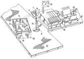
- FIG. 1is a view of a bar code reader system with dual trigger switches in a point-of-sale application environment according to the present invention
- FIG. 2 ais an enlarged top plan view of a bar code reader with a trackball (joystick) and a graphical user interface display according to the present invention
- FIG. 2 bis a perspective view of the bar code reader of FIG. 2 a;
- FIG. 2 cis an enlarged top plan view of the display of FIG. 2 a ;
- FIG. 3is a schematic block diagram of the preferred embodiment of the internal optical and electronic elements of the present invention.
- the inventionin the preferred embodiment, takes the form of a portable, hand held optical reader contained within a housing (or body) 10 of appropriate shape.
- a housingor body 10 of appropriate shape.
- the exact form of the housing 10is not of importance, and may depend upon the particular application.
- a conventional gun-shaped housingwould be suitable in many cases.
- the readermay also be arranged for hands-free use and could be fixed instead of being portable.
- the inventionprovides a system for reading coded symbols with a light source for generating a beam directed toward a symbol to be read, a detector for receiving reflected light from the symbol to produce electrical signals corresponding to data represented by the symbol, a first actuator manually displaceable from an off position to a first selectable position for initiating reading of a symbol, and an independently operable second actuator is manually displaceable from a first position to a second position to transfer said data represented by the symbol.
- the datamay be transferred to a printer, or to a display for visually displaying the data.
- the datamay also be transferred to a radio frequency or IF transmitter for wireless communication of the data to a remote receiver.
- merchandise or articles 85 having a one-dimensional bar code symbol 14are arranged on a counter 87 on which the bar code reader 10 is mounted.
- the articles 85are shown placed in a shopping tote 86 which includes an RF identification (ID) tag 88 .
- IDRF identification
- the bar code symbolsmay identify the merchandise, while the RF ID tag 88 may identify the shopper or customer.
- the tote 86may be a shipping container, and the RF ID tag denotes the destination, routing, or shipping address.
- An RF ID tag detector 69(shown in FIG. 3) may be included as part of the system. The system may employ both methods of identification, as will be subsequently described.
- FIG. 1shows a bar code reader 10 capable of both stationary and hand-held operation with dual triggers according to the present invention.
- the reader housingis depicted in the shape similar to the gun-shaped housings known in the prior art.
- the reader 10may be picked up by the user for portable use, or mounted in a stand 80 in which the reader can function operating in a fixed mode. In the fixed mode, it is positioned to read the bar code symbol 14 on a target within the field of view of the reader, such as a region of the counter 87 .
- the reader 10may make electrical contacts to the stand 80 , which in turn may be connected to a cash register 89 and/or host computer 82 which may include elements such as a display 83 and a printer 84 .
- the handle position 72 of the housing 10(i.e., the portion of the housing which is gripped by the user's hand in normal use) includes two discrete trigger switches 70 and 71 .
- the upper switch 70designed to be activated by the index finger, controls one function or operation
- the lower switch 71designed to be activated by different fingers, controls a different operation, as will be described below.
- the switches 70 , 71are independently operable and, hence, either one can be operated before, after, or simultaneously with, the other.
- a single two-position trigger switchmay be used in place of dual trigger switches. Examples of functions that may be performed by activation of the first and second positions of a dual or two-position trigger switches are as follows:
- Position Onescan
- Position Twotransfer data or operate peripheral (e.g., printer, communication and display)
- EAS deactivaterefers to an operation of hi deactivating an EAS tag on the article.
- RF IDrefers to reading an RF ID tag, such as described in U.S. Pat. No. 4,739,328.
- a single switchmay be used to activate one or more different functions. For example, the manual depression of a single momentary action switch from a first to a second position is used to activate a function. This switch need not, and typically is not, held in the second position to execute the function. The manual release of the switch does not perform any function.
- the manual depression of a single switch from a first to a second positionis used to activate a first function, e.g., aiming.
- a first functione.g., aiming.
- a second functione.g., scanning.
- FIG. 2 aillustrates the top plan view
- FIG. 2 ba perspective view of the reader 10 now shown as incorporating a display 100 and a trackball, also known as a joystick 101 .
- the joystickmay be moved by the user's thumb to move an arrow-shaped pointer 102 or indicating cursor on the display screen 100 .
- the display 100may display icons 103 which in a particular programming environment or graphical user interface may be used to refer to specific program applications, documents, or data records that may be accessed by the system.
- FIG. 1illustrates the top plan view
- FIG. 2 ba perspective view of the reader 10 now shown as incorporating a display 100 and a trackball, also known as a joystick 101 .
- the joystickmay be moved by the user's thumb to move an arrow-shaped pointer 102 or indicating cursor on the display screen 100 .
- the display 100may display icons 103 which in a particular programming environment or graphical user interface may be used to refer to specific program applications,
- FIG. 2 cshows an “AIM” icon 103 a , a “SCAN” icon 103 b , a “DEACTIVATE” icon 103 c , and a “DATA TRANSFER” icon 103 d .
- the pointer 102When the pointer 102 is moved among the phantom line positions shown in FIG. 2 c , and is aligned with the desired icon, the user can select the application or document represented by the icon by activating a switch by pressing the joystick 101 to cause it to “click” and thereby register to the system the selected icon as representing the particular application, document, or data record desired to be accessed, executed or displayed.
- aiming, scanning, tag deactivating and data transferringare executed in response to selecting icons 130 a-d , respectively.
- two “windows” representing distinct programs P 1 and P 2are displayed with the “active” or overlapping one 105 displaying data 106 .
- FIGS. 2 a and 2 balso illustrate a solar cell collector 107 which functions to power the reader and/or charge a battery contained within the reader housing 10 .
- the stand 80may be utilized in a location remote from the host computer 82 or other power source, it is advantageous to provide separate means for powering the reader.
- a solar power battery charger coupled to the solar cell collector 107achieves this objective in one embodiment of the present invention.
- microwave or heat energy sourcescould also be used.
- a microwave transmitteris installed in the close vicinity of the device (e.g., in the cash register around which a cordless scanner is used). This could be either the transmitter utilized to communicate with the portable device or one which is specific to this task. For both cases, its frequency could be either the same as the one utilized for the communication channel or a different one. Because of regulatory and safety/health issues, in most practical situations only low power levels should be generated.
- heat generated in the devicecould be used, derived from the inherent inefficiency of its components. For example if ⁇ 1 is the device inefficiency (which results in heat generation), and ⁇ 2 is the process efficiency of converting heat to electricity, then a fraction of ⁇ 1 ⁇ 2 of the battery energy can be used for its charging.
- the secondary (rechargeable) batteryis the power source which directly powers the device, and is continuously recharged at a low level (“trickle charge”) throughout the session, while maintaining the cordless mode of operation.
- the secondary batterycan be used to deliver the same overall apparent capacity to the user. In this particular case, at the end of the session the primary battery is replaced and the secondary battery is recharged. However, the overall combination provides for a session which is longer than if a single battery type were used (assuming the same total battery weight).
- the housing 10has a window 12 therein, which is arranged to be positioned by the user opposite a bar code symbol or other indicia 14 to be read.
- an illumination sourcesuch as a laser 16
- optics 18an illuminating LED or laser 20
- optics 22an illuminating LED or laser 20
- collection optics 24Behind the collection optics 24 is a detector or a two-dimensional imaging array 26 such as a CCD array which is arranged to be read out by signal processing circuitry 28 .
- the array 26could comprise any two-dimensional solid-state imaging device; it could, for example, comprise a random-access device.
- the trigger mechanismincorporates dual trigger switches 70 , 71 , such as shown in FIG. 1, having first switch contact 42 and second switch contact 44 .
- the operatorfirst pulls the first trigger 70 back to a first position, in which it meets the contact 42 .
- Thiscauses the controller 36 to actuate the laser 16 to produce a visible aiming beam 46 which the operator then manually aligns with the indicia 14 .
- the aiming beampreferably produces a static pattern, or designation pattern, preferably a point or a line which is easily visible.
- the optical system 18incorporates a cylindrical lens, such as that previously described in copending U.S. patent application Ser. No. 08/268,913 noted above in the Reference to Related Applications, to produce a solid line of light which can quite easily be aligned with the longitudinal axis of the bar code symbol.
- the controller 36switches off the laser 16 and switches on the LED or laser 20 for a predetermined period, thereby illuminating the indicia 14 with the beam 54 . If the adjustments have correctly been made, the beam will be an optimized match with the size of the code at the measured distance d. An estimate of the apparent size of the code, as seen from the window, can be determined from the known actual size of the code (where available), which may have been entered in advance by means of the keyboard 38 .
- the indicia 14is imaged onto the two-dimensional semiconductor array 26 , which is then read out by the signal processing circuitry 28 .
- the signalsare then decoded by a decoder 56 .
- Feedbackis provided to the operator by means of a display 58 and/or audio feedback means 60 .
- the controllermay automatically instruct the reader to switch itself off, or alternatively to move into a low-power quiescent mode.
- a further variationis to replace the lasers 16 , 20 with a single laser, and the optics 18 , 22 with a single set of optics.
- the same laseroperates to produce the aiming beam (designating pattern) 46 and the imaging illuminating beam 54 .
- Such an arrangementis, of course, only of assistance where the laser produces light of a wavelength which can easily be seen by the operator.
- the trigger 40could be a multi-position trigger.
- the various trigger positionscould undertake a variety of functions; for example, one trigger position might produce a first static pattern (designation pattern), with a second position producing a second pattern, and a third position producing the measurement illumination. This type of arrangement could be useful where the device is to be used in a variety of situations, or with a variety of different bar code symbols, since it would then be possible for the operator to choose an appropriate designation pattern for the indicia which is to be measured.
- trigger positions of a multi-position triggercould provide an on/off function, or other functions for controlling the information shown on the display 58 , such as deactivation of an EAS tag, reading of an RF ID tag, or activation of a peripheral device, such as a modem, radio, infrared transmission unit or other communications device, or a peripheral device such as a printer.
- a peripheral devicesuch as a modem, radio, infrared transmission unit or other communications device, or a peripheral device such as a printer.
- One examplewould be initiating wireless communication of the data represented by the symbol through a communication unit 113 connected to the controller 36 .
- Different trigger positionscould also be provided to alter the measurement characteristics of the device, for example to provide at least a certain level of manual control over the focusing and/or magnification, such as zooming or spot size adjustment. All of these features will, of course, be controlled by the controller 36 .
- FIG. 3could, instead, represent a fixed embodiment which is arranged to be built into a point-of-sale unit, for example above a conveyor.
- the automatic magnification/focus controlsenable the device to deal with a variety of different sized packages, passing along the conveyor, thereby presenting bar code symbols at a variety of different distances from the device.
Landscapes
- Physics & Mathematics (AREA)
- Engineering & Computer Science (AREA)
- Electromagnetism (AREA)
- General Physics & Mathematics (AREA)
- Theoretical Computer Science (AREA)
- Health & Medical Sciences (AREA)
- General Health & Medical Sciences (AREA)
- Toxicology (AREA)
- Artificial Intelligence (AREA)
- Computer Vision & Pattern Recognition (AREA)
- General Engineering & Computer Science (AREA)
- Image Input (AREA)
Abstract
Description
Claims (18)
Priority Applications (1)
| Application Number | Priority Date | Filing Date | Title |
|---|---|---|---|
| US09/656,575US6234394B1 (en) | 1995-03-20 | 2000-09-07 | Triggered optical reader |
Applications Claiming Priority (5)
| Application Number | Priority Date | Filing Date | Title |
|---|---|---|---|
| US08/407,577US5600121A (en) | 1995-03-20 | 1995-03-20 | Optical reader with independent triggering and graphical user interface |
| US08/686,157US5801371A (en) | 1995-03-20 | 1996-07-24 | Optical reader with independent triggering and graphical user interface |
| US08/820,048US5744791A (en) | 1996-07-24 | 1997-03-18 | Solar energy-powered optical reader |
| US09/067,124US6158662A (en) | 1995-03-20 | 1998-04-27 | Triggered optical reader |
| US09/656,575US6234394B1 (en) | 1995-03-20 | 2000-09-07 | Triggered optical reader |
Related Parent Applications (1)
| Application Number | Title | Priority Date | Filing Date |
|---|---|---|---|
| US09/067,124ContinuationUS6158662A (en) | 1995-03-20 | 1998-04-27 | Triggered optical reader |
Publications (1)
| Publication Number | Publication Date |
|---|---|
| US6234394B1true US6234394B1 (en) | 2001-05-22 |
Family
ID=27410715
Family Applications (2)
| Application Number | Title | Priority Date | Filing Date |
|---|---|---|---|
| US09/067,124Expired - LifetimeUS6158662A (en) | 1995-03-20 | 1998-04-27 | Triggered optical reader |
| US09/656,575Expired - LifetimeUS6234394B1 (en) | 1995-03-20 | 2000-09-07 | Triggered optical reader |
Family Applications Before (1)
| Application Number | Title | Priority Date | Filing Date |
|---|---|---|---|
| US09/067,124Expired - LifetimeUS6158662A (en) | 1995-03-20 | 1998-04-27 | Triggered optical reader |
Country Status (1)
| Country | Link |
|---|---|
| US (2) | US6158662A (en) |
Cited By (32)
| Publication number | Priority date | Publication date | Assignee | Title |
|---|---|---|---|---|
| US6405924B1 (en)* | 2000-01-28 | 2002-06-18 | Insta-Trek Corporation | Inventory control system and method |
| US20030006290A1 (en)* | 2001-05-02 | 2003-01-09 | Hand Held Products, Inc. | Optical reader comprising soft key including permanent graphic indicia |
| WO2003027944A1 (en)* | 2001-09-24 | 2003-04-03 | Checkpoint Systems, Inc. | Method and system for non-contact automated verification of the correctness of the identity of an item having an associated primary identifier |
| US20030197611A1 (en)* | 2002-02-01 | 2003-10-23 | Clifford Harold C. | Systems and methods for data reading and EAS tag sensing and deactivating at retail checkout |
| US20040089721A1 (en)* | 1990-09-10 | 2004-05-13 | Wilz David M. | Automatically-activated hand-supportable laser scanning bar code symbol reading system with data transmission activation switch |
| US20040189472A1 (en)* | 2002-02-01 | 2004-09-30 | Psc Scanning, Inc. | Combined data reader and electronic article surveillance (EAS) system |
| US20050040934A1 (en)* | 2003-08-22 | 2005-02-24 | Kenneth Shanton | Point-of-purchase display with RFID inventory control |
| US20050127185A1 (en)* | 1990-09-17 | 2005-06-16 | Wilz David M.Sr. | Automatically-activated hand-supportable laser scanning bar code symbol reading system with data transmission activation switch |
| US20050189422A1 (en)* | 2004-02-07 | 2005-09-01 | Wood Todd A. | Hand held scanner with rotating head |
| US6974080B1 (en) | 2002-03-01 | 2005-12-13 | National Graphics, Inc. | Lenticular bar code image |
| US20060114665A1 (en)* | 2004-11-30 | 2006-06-01 | Joseph Patino | Light detection power system and method for same |
| US20060202038A1 (en)* | 2005-03-11 | 2006-09-14 | Ynjiun Wang | System and method to automatically focus an image reader |
| US20060202036A1 (en)* | 2005-03-11 | 2006-09-14 | Ynjiun Wang | Bar code reading device with global electronic shutter control |
| US20060208894A1 (en)* | 2005-02-08 | 2006-09-21 | Friend Matthew J | Integrated data reader and electronic article surveillance (EAS) system |
| US20060208086A1 (en)* | 2005-03-15 | 2006-09-21 | Psc Scanning, Inc. | Multifunction trigger for RFID and optical readers |
| US20060274171A1 (en)* | 2005-06-03 | 2006-12-07 | Ynjiun Wang | Digital picture taking optical reader having hybrid monochrome and color image sensor array |
| US20060283952A1 (en)* | 2005-06-03 | 2006-12-21 | Wang Ynjiun P | Optical reader having reduced specular reflection read failures |
| US20070034694A1 (en)* | 2005-01-26 | 2007-02-15 | Dublin Management Associates Of New Jersey, Inc. | Interactive display system with indicia reader |
| US7287697B2 (en) | 2001-07-13 | 2007-10-30 | Hand Held Products, Inc. | Optical reader having a color imager |
| US20080136662A1 (en)* | 2006-12-06 | 2008-06-12 | David Bellows | System and Method for Activating a Mobile Device |
| US7389918B2 (en)* | 2001-10-23 | 2008-06-24 | Ncr Corporation | Automatic electronic article surveillance for self-checkout |
| US20080164315A1 (en)* | 2007-01-05 | 2008-07-10 | Hand Held Products, Inc. | Optical reader |
| USD588596S1 (en)* | 2006-02-01 | 2009-03-17 | Datalogic, S.P.A. | Coded information reader |
| USD599799S1 (en)* | 2008-02-01 | 2009-09-08 | Datalogic Scanning Group S.R.L. | Coded information reader |
| US20090321525A1 (en)* | 2008-06-30 | 2009-12-31 | Edward Barkan | Data capture terminal with multiple readers operable in handheld and hands-free modes of operation |
| USD682277S1 (en) | 2011-12-30 | 2013-05-14 | Datalogic Ip Tech S.R.L. | Coded information reader |
| CN103414850A (en)* | 2012-07-04 | 2013-11-27 | 信实数码股份有限公司 | Method for quickly setting image capturing range of pattern |
| US8629926B2 (en) | 2011-11-04 | 2014-01-14 | Honeywell International, Inc. | Imaging apparatus comprising image sensor array having shared global shutter circuitry |
| US8657200B2 (en) | 2011-06-20 | 2014-02-25 | Metrologic Instruments, Inc. | Indicia reading terminal with color frame processing |
| USD719574S1 (en) | 2014-01-09 | 2014-12-16 | Datalogic Ip Tech S.R.L. | Portable terminal |
| USD723563S1 (en) | 2012-12-21 | 2015-03-03 | Datalogic Ip Tech S.R.L. | Reader of coded information |
| CN112115730A (en)* | 2020-09-09 | 2020-12-22 | 红云红河烟草(集团)有限责任公司 | Auxiliary code reading method for associating two-dimensional codes of hand-held cigarettes |
Families Citing this family (35)
| Publication number | Priority date | Publication date | Assignee | Title |
|---|---|---|---|---|
| US6607133B2 (en) | 1990-09-10 | 2003-08-19 | Metrologic Instruments, Inc. | Automatically-activated hand-supportable laser scanning bar code symbol reading system with data transmission activation switch |
| US6308893B1 (en)* | 1995-03-20 | 2001-10-30 | Symbol Technologies, Inc. | Methods for using a bar code reader for facilitating transactions and collecting a toll based on use |
| US6976626B2 (en) | 1997-09-16 | 2005-12-20 | Metrologic Instruments, Inc. | Wireless bar code symbol driven portable data terminal (PDT) system adapted for single handed operation |
| US6729543B1 (en)* | 1998-03-06 | 2004-05-04 | Audiovelocity, Inc. | Page identification system and method |
| US7097105B2 (en)* | 1998-12-03 | 2006-08-29 | Metrologic Instruments, Inc. | Automatically-activated hand-supportable omni-directional laser scanning bar code symbol reader having a user-selectable linear scanning menu-reading mode supported by a stroboscopically-pulsed omni-directional laser scanning pattern for improved bar code symbol navigation and alignment during menu-reading operations |
| US7111786B2 (en) | 1998-12-03 | 2006-09-26 | Metrologic Instruments, Inc. | Automatically-activated wireless hand-supportable laser scanning bar code symbol reading system with data transmission activation switch and automatic communication range dependent control |
| US6394355B1 (en)* | 1999-02-22 | 2002-05-28 | Symbol Technologies, Inc. | Hand-held acquistion device |
| ES2322988T3 (en)* | 2000-02-23 | 2009-07-03 | Datalogic S.P.A. | APPARATUS AND PROCEDURE FOR READING AND DECODING OPTICAL CODES WITH INDICATION OF THE RESULT. |
| US6467688B1 (en)* | 2000-05-17 | 2002-10-22 | Symbol Technologies, Inc. | Sheet fed printer for a hand held terminal |
| US6601767B1 (en)* | 2000-08-16 | 2003-08-05 | Ncr Corporation | Ambient light sensing apparatus and method for a produce data collector |
| US20030206150A1 (en)* | 2001-05-02 | 2003-11-06 | Hand Held Products, Inc. | Optical reader comprising keyboard |
| US6715677B1 (en)* | 2001-11-13 | 2004-04-06 | Ncr Corporation | Checkout system including a product security label deactivator |
| US20040046874A1 (en)* | 2001-11-15 | 2004-03-11 | Ming-Kai Tse | Miniaturized photosensing instrumentation system |
| GB2382879A (en)* | 2001-12-06 | 2003-06-11 | Hewlett Packard Co | Image capture device with capture field illumination |
| CA2480600C (en)* | 2002-04-11 | 2015-04-07 | Sensormatic Electronics Corporation | System and method for managing assets using a portable combined electronic article surveillance system and barcode scanner |
| US6745852B2 (en)* | 2002-05-08 | 2004-06-08 | Anadarko Petroleum Corporation | Platform for drilling oil and gas wells in arctic, inaccessible, or environmentally sensitive locations |
| EP1609011B1 (en)* | 2003-04-02 | 2019-03-13 | Oracle America, Inc. | Optical communication between face-to-face semiconductor chips |
| USD512427S1 (en)* | 2003-07-08 | 2005-12-06 | Symbol Technologies, Inc. | Mobile terminal “lobster tail” handle |
| USD512063S1 (en)* | 2003-11-24 | 2005-11-29 | Market Scan Information Systems, Inc. | Data acquisition device |
| USD558768S1 (en)* | 2006-03-30 | 2008-01-01 | Symbol Technologies, Inc. | Mobile device handle |
| USD601557S1 (en) | 2007-08-06 | 2009-10-06 | Data Ltd., Inc. | Tablet computer |
| USD574838S1 (en)* | 2007-10-10 | 2008-08-12 | Symbol Technologies, Inc. | Housing for a mobile device |
| US8146824B2 (en)* | 2008-04-29 | 2012-04-03 | Symbol Technologies, Inc. | Floating trigger assembly in electro-optical reader |
| US8424768B2 (en) | 2009-04-09 | 2013-04-23 | Metrologic Instruments, Inc. | Trigger mechanism for hand held devices |
| USD654499S1 (en) | 2009-06-09 | 2012-02-21 | Data Ltd., Inc. | Tablet computer |
| USD635568S1 (en) | 2009-06-09 | 2011-04-05 | Data Ltd., Inc. | Tablet computer |
| USD638834S1 (en) | 2009-10-05 | 2011-05-31 | Data Ltd., Inc. | Tablet computer |
| WO2011163541A1 (en) | 2010-06-24 | 2011-12-29 | Avery Dennison Corporation | Hand-held portable printer |
| USD668657S1 (en) | 2010-09-01 | 2012-10-09 | Data Ltd., Inc. | Tablet computer cradle |
| USD690296S1 (en) | 2011-02-01 | 2013-09-24 | Data Ltd., Inc. | Tablet computer |
| USD662502S1 (en) | 2011-02-15 | 2012-06-26 | Data Ltd., Inc. | Tablet computer cradle |
| GB2513039A (en)* | 2012-01-17 | 2014-10-15 | Honeywell Int Inc | Industrial design for consumer device based on scanning and mobility |
| USD671121S1 (en)* | 2012-05-10 | 2012-11-20 | Trimble Navigation Limited | Handheld infra-red scanner |
| USD692004S1 (en)* | 2012-08-31 | 2013-10-22 | Megaviz Limited | Barcode scanner and radio frequency identification reader combo |
| USD729247S1 (en)* | 2014-05-29 | 2015-05-12 | Symbol Technologies, Inc. | Mobile computer |
Citations (2)
| Publication number | Priority date | Publication date | Assignee | Title |
|---|---|---|---|---|
| US5005125A (en)* | 1986-02-28 | 1991-04-02 | Sensormatic Electronics Corporation | Surveillance, pricing and inventory system |
| EP0471291A2 (en)* | 1990-08-07 | 1992-02-19 | Omron Corporation | Optical scanner |
Family Cites Families (1)
| Publication number | Priority date | Publication date | Assignee | Title |
|---|---|---|---|---|
| US5600121A (en)* | 1995-03-20 | 1997-02-04 | Symbol Technologies, Inc. | Optical reader with independent triggering and graphical user interface |
- 1998
- 1998-04-27USUS09/067,124patent/US6158662A/ennot_activeExpired - Lifetime
- 2000
- 2000-09-07USUS09/656,575patent/US6234394B1/ennot_activeExpired - Lifetime
Patent Citations (2)
| Publication number | Priority date | Publication date | Assignee | Title |
|---|---|---|---|---|
| US5005125A (en)* | 1986-02-28 | 1991-04-02 | Sensormatic Electronics Corporation | Surveillance, pricing and inventory system |
| EP0471291A2 (en)* | 1990-08-07 | 1992-02-19 | Omron Corporation | Optical scanner |
Cited By (114)
| Publication number | Priority date | Publication date | Assignee | Title |
|---|---|---|---|---|
| US20040089721A1 (en)* | 1990-09-10 | 2004-05-13 | Wilz David M. | Automatically-activated hand-supportable laser scanning bar code symbol reading system with data transmission activation switch |
| US7252238B2 (en)* | 1990-09-10 | 2007-08-07 | Metrologic Instruments, Inc. | Automatically-activated hand-supportable laser scanning bar code symbol reading system with data transmission activation switch |
| US20050127185A1 (en)* | 1990-09-17 | 2005-06-16 | Wilz David M.Sr. | Automatically-activated hand-supportable laser scanning bar code symbol reading system with data transmission activation switch |
| US7611063B2 (en) | 1990-09-17 | 2009-11-03 | Metrologic Instruments, Inc. | Automatically-activated code symbol reading system |
| US7156310B2 (en) | 1990-09-17 | 2007-01-02 | Metrologic Instruments, Inc. | Automatically-activated hand-supportable laser scanning bar code symbol reading system with data transmission activation switch |
| US20080041962A1 (en)* | 1990-09-17 | 2008-02-21 | Metrologic Instruments Inc. | Automatically-activated hand-supportable laser scanning bar code symbol reading system with data transmission activation switch |
| US6405924B1 (en)* | 2000-01-28 | 2002-06-18 | Insta-Trek Corporation | Inventory control system and method |
| US20030006290A1 (en)* | 2001-05-02 | 2003-01-09 | Hand Held Products, Inc. | Optical reader comprising soft key including permanent graphic indicia |
| US6899273B2 (en) | 2001-05-02 | 2005-05-31 | Hand Held Products, Inc. | Optical reader comprising soft key including permanent graphic indicia |
| US8292180B2 (en) | 2001-07-13 | 2012-10-23 | Hand Held Products, Inc. | Optical reader having an imager |
| US7287697B2 (en) | 2001-07-13 | 2007-10-30 | Hand Held Products, Inc. | Optical reader having a color imager |
| US7686222B2 (en) | 2001-07-13 | 2010-03-30 | Hand Held Products, Inc. | Optical reader having a color imager |
| US8528818B2 (en) | 2001-07-13 | 2013-09-10 | Hand Held Products, Inc. | Optical reader having an imager |
| US7413127B2 (en) | 2001-07-13 | 2008-08-19 | Hand Held Products, Inc. | Optical reader for classifying an image |
| WO2003027944A1 (en)* | 2001-09-24 | 2003-04-03 | Checkpoint Systems, Inc. | Method and system for non-contact automated verification of the correctness of the identity of an item having an associated primary identifier |
| US7389918B2 (en)* | 2001-10-23 | 2008-06-24 | Ncr Corporation | Automatic electronic article surveillance for self-checkout |
| US8011579B2 (en) | 2002-02-01 | 2011-09-06 | Datalogic Scanning, Inc. | Combined data reader and electronic article surveillance (EAS) system |
| US7132947B2 (en)* | 2002-02-01 | 2006-11-07 | Psc Scanning, Inc. | Systems and methods for data reading and EAS tag sensing and deactivating at retail checkout |
| US7495564B2 (en) | 2002-02-01 | 2009-02-24 | Datalogic Scanning, Inc. | Systems and methods for data reading and EAS tag sensing and deactivating at retail checkout |
| US7170414B2 (en)* | 2002-02-01 | 2007-01-30 | Psc Scanning, Inc. | Systems and methods for optical reading and EAS tag sensing and deactivating at retail checkout |
| US20050219053A1 (en)* | 2002-02-01 | 2005-10-06 | Psc Scanning, Inc. | Systems and methods for optical reading and EAS tag sensing and deactivating at retail checkout |
| US20070210922A1 (en)* | 2002-02-01 | 2007-09-13 | Psc Scanning, Inc. | Systems and methods for data reading and EAS tag sensing and deactivating at retail checkout |
| US20040189472A1 (en)* | 2002-02-01 | 2004-09-30 | Psc Scanning, Inc. | Combined data reader and electronic article surveillance (EAS) system |
| US20030197611A1 (en)* | 2002-02-01 | 2003-10-23 | Clifford Harold C. | Systems and methods for data reading and EAS tag sensing and deactivating at retail checkout |
| US6974080B1 (en) | 2002-03-01 | 2005-12-13 | National Graphics, Inc. | Lenticular bar code image |
| US7672872B2 (en)* | 2003-08-22 | 2010-03-02 | Smurfit-Stone Container Enterprises, Inc. | Point-of-purchase display with RFID inventory control |
| US20050040934A1 (en)* | 2003-08-22 | 2005-02-24 | Kenneth Shanton | Point-of-purchase display with RFID inventory control |
| US20050189422A1 (en)* | 2004-02-07 | 2005-09-01 | Wood Todd A. | Hand held scanner with rotating head |
| US7370802B2 (en)* | 2004-02-07 | 2008-05-13 | Siemens Energy & Automation, Inc. | Hand held scanner with rotating head |
| US7800046B2 (en) | 2004-11-30 | 2010-09-21 | Motorola Mobility, Inc. | Light detection power system and method for same |
| US7486044B2 (en) | 2004-11-30 | 2009-02-03 | Motorola, Inc. | Light detection power system and method for same |
| US20060114665A1 (en)* | 2004-11-30 | 2006-06-01 | Joseph Patino | Light detection power system and method for same |
| US20090128089A1 (en)* | 2004-11-30 | 2009-05-21 | Motorola, Inc. | Light detection power system and method for same |
| US20070034694A1 (en)* | 2005-01-26 | 2007-02-15 | Dublin Management Associates Of New Jersey, Inc. | Interactive display system with indicia reader |
| US20060208894A1 (en)* | 2005-02-08 | 2006-09-21 | Friend Matthew J | Integrated data reader and electronic article surveillance (EAS) system |
| US7619527B2 (en) | 2005-02-08 | 2009-11-17 | Datalogic Scanning, Inc. | Integrated data reader and electronic article surveillance (EAS) system |
| US9578269B2 (en) | 2005-03-11 | 2017-02-21 | Hand Held Products, Inc. | Image reader comprising CMOS based image sensor array |
| US10735684B2 (en) | 2005-03-11 | 2020-08-04 | Hand Held Products, Inc. | Image reader comprising CMOS based image sensor array |
| US7568628B2 (en) | 2005-03-11 | 2009-08-04 | Hand Held Products, Inc. | Bar code reading device with global electronic shutter control |
| US7611060B2 (en) | 2005-03-11 | 2009-11-03 | Hand Held Products, Inc. | System and method to automatically focus an image reader |
| US12185006B2 (en) | 2005-03-11 | 2024-12-31 | Hand Held Products, Inc. | Image reader comprising CMOS based image sensor array |
| US12075176B2 (en) | 2005-03-11 | 2024-08-27 | Hand Held Products, Inc. | Image reader comprising CMOS based image sensor array |
| US11968464B2 (en) | 2005-03-11 | 2024-04-23 | Hand Held Products, Inc. | Image reader comprising CMOS based image sensor array |
| US20100044440A1 (en)* | 2005-03-11 | 2010-02-25 | Hand Held Products, Inc. | System and method to automatically focus an image reader |
| US11863897B2 (en) | 2005-03-11 | 2024-01-02 | Hand Held Products, Inc. | Image reader comprising CMOS based image sensor array |
| US11323650B2 (en) | 2005-03-11 | 2022-05-03 | Hand Held Products, Inc. | Image reader comprising CMOS based image sensor array |
| US11323649B2 (en) | 2005-03-11 | 2022-05-03 | Hand Held Products, Inc. | Image reader comprising CMOS based image sensor array |
| US11317050B2 (en) | 2005-03-11 | 2022-04-26 | Hand Held Products, Inc. | Image reader comprising CMOS based image sensor array |
| US10958863B2 (en) | 2005-03-11 | 2021-03-23 | Hand Held Products, Inc. | Image reader comprising CMOS based image sensor array |
| US8720781B2 (en) | 2005-03-11 | 2014-05-13 | Hand Held Products, Inc. | Image reader having image sensor array |
| US10721429B2 (en) | 2005-03-11 | 2020-07-21 | Hand Held Products, Inc. | Image reader comprising CMOS based image sensor array |
| US10171767B2 (en) | 2005-03-11 | 2019-01-01 | Hand Held Products, Inc. | Image reader comprising CMOS based image sensor array |
| US7909257B2 (en) | 2005-03-11 | 2011-03-22 | Hand Held Products, Inc. | Apparatus having coordinated exposure period and illumination period |
| US20060202038A1 (en)* | 2005-03-11 | 2006-09-14 | Ynjiun Wang | System and method to automatically focus an image reader |
| US9576169B2 (en) | 2005-03-11 | 2017-02-21 | Hand Held Products, Inc. | Image reader having image sensor array |
| US9465970B2 (en) | 2005-03-11 | 2016-10-11 | Hand Held Products, Inc. | Image reader comprising CMOS based image sensor array |
| US8146820B2 (en) | 2005-03-11 | 2012-04-03 | Hand Held Products, Inc. | Image reader having image sensor array |
| US9305199B2 (en) | 2005-03-11 | 2016-04-05 | Hand Held Products, Inc. | Image reader having image sensor array |
| US8733660B2 (en) | 2005-03-11 | 2014-05-27 | Hand Held Products, Inc. | Image reader comprising CMOS based image sensor array |
| US8978985B2 (en) | 2005-03-11 | 2015-03-17 | Hand Held Products, Inc. | Image reader comprising CMOS based image sensor array |
| US20060202036A1 (en)* | 2005-03-11 | 2006-09-14 | Ynjiun Wang | Bar code reading device with global electronic shutter control |
| US20060208086A1 (en)* | 2005-03-15 | 2006-09-21 | Psc Scanning, Inc. | Multifunction trigger for RFID and optical readers |
| US11238251B2 (en) | 2005-06-03 | 2022-02-01 | Hand Held Products, Inc. | Apparatus having hybrid monochrome and color image sensor array |
| US11625550B2 (en) | 2005-06-03 | 2023-04-11 | Hand Held Products, Inc. | Apparatus having hybrid monochrome and color image sensor array |
| US12321813B2 (en) | 2005-06-03 | 2025-06-03 | Hand Held Products, Inc. | Apparatus having hybrid monochrome and color image sensor array |
| US12321815B2 (en) | 2005-06-03 | 2025-06-03 | Hand Held Products, Inc. | Apparatus having hybrid monochrome and color image sensor array |
| US8720785B2 (en) | 2005-06-03 | 2014-05-13 | Hand Held Products, Inc. | Apparatus having hybrid monochrome and color image sensor array |
| US8720784B2 (en) | 2005-06-03 | 2014-05-13 | Hand Held Products, Inc. | Digital picture taking optical reader having hybrid monochrome and color image sensor array |
| US12321814B2 (en) | 2005-06-03 | 2025-06-03 | Hand Held Products, Inc. | Apparatus having hybrid monochrome and color image sensor array |
| US12236312B2 (en) | 2005-06-03 | 2025-02-25 | Hand Held Products, Inc. | Apparatus having hybrid monochrome and color image sensor array |
| US12073283B2 (en) | 2005-06-03 | 2024-08-27 | Hand Held Products, Inc. | Apparatus having hybrid monochrome and color image sensor array |
| US12026580B2 (en) | 2005-06-03 | 2024-07-02 | Hand Held Products, Inc. | Apparatus having hybrid monochrome and color image sensor array |
| US12020111B2 (en) | 2005-06-03 | 2024-06-25 | Hand Held Products, Inc. | Apparatus having hybrid monochrome and color image sensor array |
| US9058527B2 (en) | 2005-06-03 | 2015-06-16 | Hand Held Products, Inc. | Apparatus having hybrid monochrome and color image sensor array |
| US12001914B2 (en) | 2005-06-03 | 2024-06-04 | Hand Held Products, Inc. | Apparatus having hybrid monochrome and color image sensor array |
| US9092654B2 (en) | 2005-06-03 | 2015-07-28 | Hand Held Products, Inc. | Digital picture taking optical reader having hybrid monochrome and color image sensor array |
| US12001913B2 (en) | 2005-06-03 | 2024-06-04 | Hand Held Products, Inc. | Apparatus having hybrid monochrome and color image sensor array |
| US8196839B2 (en) | 2005-06-03 | 2012-06-12 | Hand Held Products, Inc. | Optical reader having reduced specular reflection read failures |
| US11604933B2 (en) | 2005-06-03 | 2023-03-14 | Hand Held Products, Inc. | Apparatus having hybrid monochrome and color image sensor array |
| US9438867B2 (en) | 2005-06-03 | 2016-09-06 | Hand Held Products, Inc. | Digital picture taking optical reader having hybrid monochrome and color image sensor array |
| US9454686B2 (en) | 2005-06-03 | 2016-09-27 | Hand Held Products, Inc. | Apparatus having hybrid monochrome and color image sensor array |
| US7770799B2 (en) | 2005-06-03 | 2010-08-10 | Hand Held Products, Inc. | Optical reader having reduced specular reflection read failures |
| US7780089B2 (en) | 2005-06-03 | 2010-08-24 | Hand Held Products, Inc. | Digital picture taking optical reader having hybrid monochrome and color image sensor array |
| US20060274171A1 (en)* | 2005-06-03 | 2006-12-07 | Ynjiun Wang | Digital picture taking optical reader having hybrid monochrome and color image sensor array |
| US8002188B2 (en) | 2005-06-03 | 2011-08-23 | Hand Held Products, Inc. | Method utilizing digital picture taking optical reader having hybrid monochrome and color image sensor |
| US10002272B2 (en) | 2005-06-03 | 2018-06-19 | Hand Held Products, Inc. | Apparatus having hybrid monochrome and color image sensor array |
| US20110049245A1 (en)* | 2005-06-03 | 2011-03-03 | Wang Ynjiun P | Optical reader having reduced specular reflection read failures |
| US10691907B2 (en) | 2005-06-03 | 2020-06-23 | Hand Held Products, Inc. | Apparatus having hybrid monochrome and color image sensor array |
| US11238252B2 (en) | 2005-06-03 | 2022-02-01 | Hand Held Products, Inc. | Apparatus having hybrid monochrome and color image sensor array |
| US20100315536A1 (en)* | 2005-06-03 | 2010-12-16 | Hand Held Products, Inc. | Method utilizing digital picture taking optical reader having hybrid monochrome and color image sensor |
| US20060283952A1 (en)* | 2005-06-03 | 2006-12-21 | Wang Ynjiun P | Optical reader having reduced specular reflection read failures |
| US10949634B2 (en) | 2005-06-03 | 2021-03-16 | Hand Held Products, Inc. | Apparatus having hybrid monochrome and color image sensor array |
| USD588596S1 (en)* | 2006-02-01 | 2009-03-17 | Datalogic, S.P.A. | Coded information reader |
| US20080136662A1 (en)* | 2006-12-06 | 2008-06-12 | David Bellows | System and Method for Activating a Mobile Device |
| US7878406B2 (en)* | 2007-01-05 | 2011-02-01 | Hand Held Products, Inc. | Optical reader |
| US20080164315A1 (en)* | 2007-01-05 | 2008-07-10 | Hand Held Products, Inc. | Optical reader |
| USD606076S1 (en) | 2008-02-01 | 2009-12-15 | Datalogic Scanning Group S.R.L. | Coded information reader |
| USD599799S1 (en)* | 2008-02-01 | 2009-09-08 | Datalogic Scanning Group S.R.L. | Coded information reader |
| US8028920B2 (en)* | 2008-06-30 | 2011-10-04 | Symbol Technologies, Inc. | Data capture terminal with multiple readers operable in handheld and hands-free modes of operation |
| US20090321525A1 (en)* | 2008-06-30 | 2009-12-31 | Edward Barkan | Data capture terminal with multiple readers operable in handheld and hands-free modes of operation |
| US8657200B2 (en) | 2011-06-20 | 2014-02-25 | Metrologic Instruments, Inc. | Indicia reading terminal with color frame processing |
| US8910875B2 (en) | 2011-06-20 | 2014-12-16 | Metrologic Instruments, Inc. | Indicia reading terminal with color frame processing |
| US9407840B2 (en) | 2011-11-04 | 2016-08-02 | Honeywell International, Inc. | Imaging apparatus comprising image sensor array having shared global shutter circuitry |
| US8629926B2 (en) | 2011-11-04 | 2014-01-14 | Honeywell International, Inc. | Imaging apparatus comprising image sensor array having shared global shutter circuitry |
| US9066032B2 (en) | 2011-11-04 | 2015-06-23 | Honeywell International Inc. | Imaging apparatus comprising image sensor array having shared global shutter circuitry |
| USD682277S1 (en) | 2011-12-30 | 2013-05-14 | Datalogic Ip Tech S.R.L. | Coded information reader |
| USD702238S1 (en) | 2011-12-30 | 2014-04-08 | Datalogic Ip Tech S.R.L. | Coded information reader |
| CN103414850B (en)* | 2012-07-04 | 2016-12-28 | 信实数码股份有限公司 | Method for quickly setting image capturing range of pattern |
| CN103414850A (en)* | 2012-07-04 | 2013-11-27 | 信实数码股份有限公司 | Method for quickly setting image capturing range of pattern |
| USD723563S1 (en) | 2012-12-21 | 2015-03-03 | Datalogic Ip Tech S.R.L. | Reader of coded information |
| USD719574S1 (en) | 2014-01-09 | 2014-12-16 | Datalogic Ip Tech S.R.L. | Portable terminal |
| USD740295S1 (en) | 2014-01-09 | 2015-10-06 | Datalogic Ip Tech S.R.L. | Supporting base for a portable terminal |
| CN112115730A (en)* | 2020-09-09 | 2020-12-22 | 红云红河烟草(集团)有限责任公司 | Auxiliary code reading method for associating two-dimensional codes of hand-held cigarettes |
| CN112115730B (en)* | 2020-09-09 | 2023-04-14 | 红云红河烟草(集团)有限责任公司 | Auxiliary code reading method for hand-packed cigarette two-dimensional code association |
Also Published As
| Publication number | Publication date |
|---|---|
| US6158662A (en) | 2000-12-12 |
Similar Documents
| Publication | Publication Date | Title |
|---|---|---|
| US6234394B1 (en) | Triggered optical reader | |
| US5600121A (en) | Optical reader with independent triggering and graphical user interface | |
| US6415982B2 (en) | Triggered data collector and data transmitter | |
| US5744791A (en) | Solar energy-powered optical reader | |
| US6398112B1 (en) | Apparatus and method for reading indicia using charge coupled device and scanning laser beam technology | |
| US6708883B2 (en) | Apparatus and method for reading indicia using charge coupled device and scanning laser beam technology | |
| US5262628A (en) | Narrow-bodied, single- and twin-windowed portable laser scanning head for reading bar code symbols | |
| US5621203A (en) | Method and apparatus for reading two-dimensional bar code symbols with an elongated laser line | |
| US5189291A (en) | Bar code reader operable as remote scanner or with fixed terminal | |
| US5883373A (en) | Object-sensing workstation with adjustable scanning head | |
| US5321246A (en) | Bar code scanner with RF coupling to base terminal and automatic turn-off upon decode | |
| EP1573648B1 (en) | Image scanning device having a system for determining the distance to a target | |
| US7389933B2 (en) | Triggerless electro-optical reader | |
| US5923021A (en) | Light collection systems in electro-optical readers | |
| US5117098A (en) | Multi-position trigger for control over aiming and symbol reading in a portable laser diode scanning head | |
| US5664229A (en) | Accessory for conversion with housing with first connection includes host cable and host connector and second connection including a plug-in modular connector | |
| EP0355355B1 (en) | Portable scanning system including a surveillance tag deactivator | |
| US20080078839A1 (en) | Electro-optical reader with object sensor | |
| EP0467015B1 (en) | Arrangement for and method of updating inventory markings | |
| US7497382B2 (en) | Method of and control switch arrangement for controlling different operational states in an electro-optical reader | |
| EP0770970B1 (en) | Laser scanning system for reading bar codes | |
| US7210632B2 (en) | On-axis control over scanning beam spot size and shape in electro-optical readers | |
| JP3069191B2 (en) | Scanning head of optical scanning device | |
| US20090057412A1 (en) | Diagnosing malfunction of electro-optical reader | |
| EP0366899A2 (en) | Retro-reflective laser diode scanner with beam position control |
Legal Events
| Date | Code | Title | Description |
|---|---|---|---|
| AS | Assignment | Owner name:SYMBOL TECHNOLOGIES, INC., NEW YORK Free format text:ASSIGNMENT OF ASSIGNORS INTEREST;ASSIGNOR:LERT, JOHN;REEL/FRAME:011643/0574 Effective date:20010203 Owner name:SYMBOL TECHNOLOGIES, INC., NEW YORK Free format text:ASSIGNMENT OF ASSIGNORS INTEREST;ASSIGNOR:KAHN, JOEL;REEL/FRAME:011643/0588 Effective date:20010215 | |
| STCF | Information on status: patent grant | Free format text:PATENTED CASE | |
| FPAY | Fee payment | Year of fee payment:4 | |
| AS | Assignment | Owner name:JPMORGAN CHASE BANK, N.A., NEW YORK Free format text:SECURITY INTEREST;ASSIGNOR:SYMBOL TECHNOLOGIES, INC.;REEL/FRAME:016116/0203 Effective date:20041229 | |
| FPAY | Fee payment | Year of fee payment:8 | |
| AS | Assignment | Owner name:SYMBOL TECHNOLOGIES, INC., NEW YORK Free format text:RELEASE BY SECURED PARTY;ASSIGNOR:JPMORGANCHASE BANK, N.A.;REEL/FRAME:025441/0228 Effective date:20060901 | |
| FPAY | Fee payment | Year of fee payment:12 | |
| AS | Assignment | Owner name:MORGAN STANLEY SENIOR FUNDING, INC. AS THE COLLATERAL AGENT, MARYLAND Free format text:SECURITY AGREEMENT;ASSIGNORS:ZIH CORP.;LASER BAND, LLC;ZEBRA ENTERPRISE SOLUTIONS CORP.;AND OTHERS;REEL/FRAME:034114/0270 Effective date:20141027 Owner name:MORGAN STANLEY SENIOR FUNDING, INC. AS THE COLLATE Free format text:SECURITY AGREEMENT;ASSIGNORS:ZIH CORP.;LASER BAND, LLC;ZEBRA ENTERPRISE SOLUTIONS CORP.;AND OTHERS;REEL/FRAME:034114/0270 Effective date:20141027 | |
| AS | Assignment | Owner name:SYMBOL TECHNOLOGIES, LLC, NEW YORK Free format text:CHANGE OF NAME;ASSIGNOR:SYMBOL TECHNOLOGIES, INC.;REEL/FRAME:036083/0640 Effective date:20150410 | |
| AS | Assignment | Owner name:SYMBOL TECHNOLOGIES, INC., NEW YORK Free format text:RELEASE BY SECURED PARTY;ASSIGNOR:MORGAN STANLEY SENIOR FUNDING, INC.;REEL/FRAME:036371/0738 Effective date:20150721 |