US6233466B1 - Downlink beamforming using beam sweeping and subscriber feedback - Google Patents
Downlink beamforming using beam sweeping and subscriber feedbackDownload PDFInfo
- Publication number
- US6233466B1 US6233466B1US09/289,774US28977499AUS6233466B1US 6233466 B1US6233466 B1US 6233466B1US 28977499 AUS28977499 AUS 28977499AUS 6233466 B1US6233466 B1US 6233466B1
- Authority
- US
- United States
- Prior art keywords
- beams
- base station
- subscriber
- antenna array
- control signal
- Prior art date
- Legal status (The legal status is an assumption and is not a legal conclusion. Google has not performed a legal analysis and makes no representation as to the accuracy of the status listed.)
- Expired - Lifetime
Links
- 238000010408sweepingMethods0.000titleabstractdescription53
- 238000000034methodMethods0.000claimsabstractdescription65
- 238000004891communicationMethods0.000claimsabstractdescription11
- 230000003044adaptive effectEffects0.000claimsabstractdescription5
- 230000002123temporal effectEffects0.000claims5
- 230000000737periodic effectEffects0.000abstractdescription3
- 239000013256coordination polymerSubstances0.000description39
- 230000005540biological transmissionEffects0.000description19
- 101000583175Homo sapiens Prolactin-inducible proteinProteins0.000description8
- 101000898291Nicotiana tabacum Catalase isozyme 1Proteins0.000description8
- 102100030350Prolactin-inducible proteinHuman genes0.000description8
- 101000979255Sus scrofa Neurolysin, mitochondrialProteins0.000description8
- 238000009826distributionMethods0.000description8
- 238000013459approachMethods0.000description7
- 230000001413cellular effectEffects0.000description5
- 230000004044responseEffects0.000description4
- 238000012549trainingMethods0.000description4
- 238000012935AveragingMethods0.000description3
- 230000000694effectsEffects0.000description3
- 238000005562fadingMethods0.000description3
- 238000012545processingMethods0.000description3
- 230000001419dependent effectEffects0.000description2
- 238000001514detection methodMethods0.000description2
- 238000010586diagramMethods0.000description2
- 238000001914filtrationMethods0.000description2
- PCHJSUWPFVWCPO-UHFFFAOYSA-NgoldChemical compound[Au]PCHJSUWPFVWCPO-UHFFFAOYSA-N0.000description2
- 239000010931goldSubstances0.000description2
- 229910052737goldInorganic materials0.000description2
- 230000002452interceptive effectEffects0.000description2
- 238000001228spectrumMethods0.000description2
- 230000004075alterationEffects0.000description1
- 230000008901benefitEffects0.000description1
- 230000001427coherent effectEffects0.000description1
- 230000000593degrading effectEffects0.000description1
- 230000002045lasting effectEffects0.000description1
- 238000012986modificationMethods0.000description1
- 230000004048modificationEffects0.000description1
- 238000010606normalizationMethods0.000description1
- 230000008569processEffects0.000description1
- 230000035945sensitivityEffects0.000description1
- 230000008054signal transmissionEffects0.000description1
- 238000010561standard procedureMethods0.000description1
Images


Classifications
- H—ELECTRICITY
- H04—ELECTRIC COMMUNICATION TECHNIQUE
- H04W—WIRELESS COMMUNICATION NETWORKS
- H04W16/00—Network planning, e.g. coverage or traffic planning tools; Network deployment, e.g. resource partitioning or cells structures
- H04W16/24—Cell structures
- H04W16/28—Cell structures using beam steering
- H—ELECTRICITY
- H01—ELECTRIC ELEMENTS
- H01Q—ANTENNAS, i.e. RADIO AERIALS
- H01Q1/00—Details of, or arrangements associated with, antennas
- H01Q1/12—Supports; Mounting means
- H01Q1/22—Supports; Mounting means by structural association with other equipment or articles
- H01Q1/24—Supports; Mounting means by structural association with other equipment or articles with receiving set
- H01Q1/241—Supports; Mounting means by structural association with other equipment or articles with receiving set used in mobile communications, e.g. GSM
- H01Q1/246—Supports; Mounting means by structural association with other equipment or articles with receiving set used in mobile communications, e.g. GSM specially adapted for base stations
- H—ELECTRICITY
- H01—ELECTRIC ELEMENTS
- H01Q—ANTENNAS, i.e. RADIO AERIALS
- H01Q25/00—Antennas or antenna systems providing at least two radiating patterns
- H—ELECTRICITY
- H04—ELECTRIC COMMUNICATION TECHNIQUE
- H04B—TRANSMISSION
- H04B7/00—Radio transmission systems, i.e. using radiation field
- H04B7/02—Diversity systems; Multi-antenna system, i.e. transmission or reception using multiple antennas
- H04B7/04—Diversity systems; Multi-antenna system, i.e. transmission or reception using multiple antennas using two or more spaced independent antennas
- H04B7/0408—Diversity systems; Multi-antenna system, i.e. transmission or reception using multiple antennas using two or more spaced independent antennas using two or more beams, i.e. beam diversity
Definitions
- the present inventionrelates to wireless communication systems. More specifically, the invention relates to methods for adaptive spatial beamforming in the downlink of a cellular radio communications system.
- FDMAfrequency division multiple access
- a standard technique used by commercial wireless phone systems to increase capacityis to divide the service region into spatial cells. Instead of using just one base station to serve all users in the region, a collection of base stations are used to independently service separate spatial cells. In such a cellular system, multiple users can reuse the same frequency channel without interfering with each other, provided they access the system from separated spatial cells.
- the cellular concepttherefore, is a simple type of spatial division multiple access (SDMA).
- SDMAspatial division multiple access
- the base station for each cellcontinually broadcasts an omni-directional control signal to all users in the cell. This signal is traditionally transmitted on a special control channel and can contain various types of information for signal synchronization, control, etc.
- TDMAtime division multiple access
- CDMAcode division multiple access
- TDMAallows several users to share a single frequency channel by assigning their data to distinct time slots.
- CDMAis normally a spread-spectrum technique that does not limit individual signals to narrow frequency channels but spreads them throughout the frequency spectrum of the entire band. Signals sharing the band are distinguished by assigning them different orthogonal digital code sequences.
- CDMAis generally considered the most promising multiple access technique in the cellular telephone industry.
- CDMA-based system capacitydepends very much on the ability to provide for very accurate power control; but in a mobile environment, the signal may fluctuate too fast for the system to manage effective control.
- mobile wireless environmentsare often characterized by unstable signal propagation, severe signal attenuation between the communicating entities and co-channel interference by other radio sources.
- many urban environmentscontain a significant number of reflectors (such as buildings), causing a signal to follow multiple paths from the transmitter to the receiver. Because the separate parts of such a multipath signal can arrive with different phases that destructively interfere, multipath can result in unpredictable signal fading.
- radiated poweris increased, thereby increasing interference between base stations and significantly degrading overall system performance.
- One well-known SDMA techniqueprovides the base station with a set of independently controlled directional antennas, thereby dividing the cell into separate fixed sectors, each controlled by a separate antenna.
- the base stationIn order to allow the subscriber units to distinguish separate sectors in a cell, the base station continually broadcasts in each sector a fixed directional control signal that is unique to the sector.
- This techniqueallows subscribers in separate spatial sectors of the same cell to be spatially distinguished by the base station. As a result, the frequency reuse in the system can be increased and/or cochannel interference can be reduced.
- a similar but more complex techniquecan be implemented using a coherently controlled antenna array instead of independently controlled directional antennas to form fixed sectored beams.
- predetermined downlink beamscan be formed in the directions of the separate sectors. Similar signal processing can be used to selectively receive uplink signals only from within the distinct sectors. These sectoring techniques, however, only provide a relatively small increase in capacity compared to what is theoretically possible.
- Gerlach et al.U.S. Pat. No. 5,471,647 and U.S. Pat. No. 5,634,199
- Barratt et al.U.S. Pat. No. 5,592,490
- the base stationdetermines the spatial channel of each subscriber and uses this channel information to adaptively control its antenna array to form customized narrow beams. These beams transmit an information signal over multiple paths so that the signal arrives to the subscriber with maximum strength.
- the beamscan also be selected to direct nulls to other subscribers so that cochannel interference is reduced.
- the base stationuses the channel information to spatially filter the received signals so that the uplink signal is received with maximum sensitivity and distinguished from the signals transmitted by other subscribers.
- the interference between base stationscan be reduced and the carrier-to-interference ratio at the base station receivers can be increased.
- Borras et al.U.S. Pat. No. 5,303,240 discloses a technique wherein a subscriber transmits a training signal in the uplink to a base station with an antenna array during a training mode. After the antenna array determines the beams corresponding to the best uplink reception during this training mode, the array then uses these beams for uplink and downlink beamforming.
- This techniquedoes not accurately measure correct downlink spatial beam information because the spatial channel is frequency dependent and the uplink and downlink frequencies are often different.
- the technique of Borrasalso suffers from the disadvantage that a separate training mode is required to determine the spatial channel. This approach has the disadvantage that the information transmission mode must be interrupted frequently to update the beam information whenever the propagation environment is not stable.
- a technique for obtaining actual downlink channel informationis to transmit probing signals and receive feedback from the subscriber, as taught by Gerlach et al.
- Gerlach's probing signalsare omni-directional signals transmitted separately from the individual antennas in the array.
- the subscriberdetects the probing signals and determines the downlink spatial channel for each antenna.
- This downlink channel informationis then sent back to the base station by the subscriber.
- the base stationcan then use the downlink channel information when transmitting downlink signals, thereby improving system performance.
- Gelach's techniquehas the significant problem that in typical environments where the propagation environment is changing, it requires very high feedback rates to transmit channel information for all the antennas.
- the present inventionprovides a method for wireless communication that adaptively exploits the spatial domain in the downlink without requiring computationally complex processing. Surprisingly, the method provides a technique for accurately estimating the downlink spatial channel while maintaining simplicity of implementation. In contrast with prior downlink beamforming techniques that assume the uplink and downlink spatial channels are identical, the present invention accurately estimates the downlink channel even when it differs significantly from the uplink channel. In addition, the present invention does not suffer from prohibitively large feedback rates, as do known techniques for estimating the downlink channel.
- a method for downlink beamforming in a wireless communication systeminvolves using an antenna array to transmit downlink control signals from the base station to the subscribers in the cell.
- the control signal in the present systemis transmitted for only a short time interval in a specified directional beam.
- the control signal beamis then retransmitted again in the same direction.
- control signal beamsare also transmitted in other specified directions. In one embodiment, for example, control signal beams sweep around the base station once during each cycle, similar to the operation of a lighthouse.
- sweepingwill be defined to apply to any complete covering of the cell by a sequence of beams, whether or not temporally successive beams are adjacent to each other.
- the beamsmay have various shapes and may partially overlap with each other. In any case, however, each beam must have angular asymmetry, i.e., does not have an omni-directional power distribution.
- the beamsmust also be transmitted in distinct angular directions relative to the base station.
- the directions and beam patternsare preferably controlled electronically, other techniques may also be used for controlling the beams, e.g., mechanical rotation of an antenna platform.
- the sweeping of the control signal beams over the cellis repeated indefinitely.
- a subscriber located in the cellwill receive a repeating pattern of signal pulses.
- there will be a peak pulse corresponding to the control beam directed toward the subscriberand two or more weaker pulses corresponding to the beams directed slightly to one side or the other of the subscriber.
- Typical signal propagation environmentshowever, often are characterized by multipath effects.
- the peak pulsedoes not always correspond to the beam transmitted in the direction of the subscriber.
- the repeating pattern of control signal pulses received by the subscriberwill be a function of both the transmitted sweeping beam pattern and the radio signal propagation environment.
- the subscribercan easily estimate from the pattern of received signal pulses the optimal downlink beam or combination of beams. This information is then transmitted back to the base station, which uses it to transmit information to the subscriber using the optimal downlink beam, or combination of beams. Meanwhile, the subscriber continues to monitor the pattern of control beam pulses, and notifies the base station if the optimal downlink beam or beams changes.
- all base station control signalsare transmitted through the sequence of beams sweeping the sectors of the cell.
- some of the control signalsare transmitted continuously in all directions, or continuously in each fixed sector, while other control signals are transmitted as part of the sweeping beam.
- the control signal transmission from the base stationis a superimposition of a directional beam containing primary control signals and an omni-directional signal containing secondary control signals. In other words, in the direction of the beam, there is additional radiant power injected (e.g., a few dB) for that time slot.
- the subscriberreceives control signal pulses corresponding to the beam sweeps, estimates optimal downlink beam information from the received pattern of pulses, and transmits this information to the base station for use in downlink information transmission.
- the subscribercontinually monitors the pattern of control pulses and notifies the base station if the optimal beams for downlink transmission changes.
- FIG. 1provides a general view of the system architecture of a base station according to a preferred embodiment of the present invention.
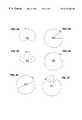
- FIG. 2Aillustrates an example of a sequence of non-overlapping control beams covering a base station cell according to an embodiment of the present invention.
- FIG. 2Billustrates a first beam used to transmit control channel information during a first time slot of a beam sweeping cycle, according to an embodiment of the present invention.
- FIG. 2Cillustrates a second beam used to transmit control channel information during a second time slot of a beam sweeping cycle, according to an embodiment of the present invention.
- FIG. 3is a diagram illustrating the timing of various transmissions during a sweeping cycle according to a preferred embodiment of the invention.
- FIGS. 4A-4Hshow a sequence of antenna beam patterns generated by a base station during a sweep cycle according to an embodiment of the present invention.
- FIGS. 5A-5Fshow six different possibilities for sweeping beam power distribution patterns that might be used in various embodiments of the present invention.
- FIG. 1provides a schematic block diagram of a base station according to a preferred embodiment of the present invention.
- the base stationcomprises an antenna array having N antenna elements.
- the number N of antenna elementsis approximately 16 for a 360° cell. For cells having less than 360° coverage fewer antennas would be needed.
- the N antenna elementsare coupled to a corresponding set of N antenna duplexers that allow the array to be used for both transmission and reception, as is well known in the art.
- the embodimentallows for low cost duplexers and antenna filters since beam forming does not require high power per antenna element in order to provide the required effective radiated power (ERP).
- ERPeffective radiated power
- the N antenna duplexersarc coupled to a corresponding set of N low-noise amplifiers (LNAs) which amplify the signals received at the corresponding set of N antenna elements.
- LNAslow-noise amplifiers
- the amplified signals from the LNAsare all coupled to a receiver beam-forming circuit, which spatially filters the uplink signals coherently received at the antenna array.
- the receiver beam-forming circuitalso down-converts the incoming signals in frequency and digitizes them to produce received digital data.
- a compensation circuitis provided.
- the compensation circuitis coupled to the antenna array and measures the phase and amplitude response of each signal by embedding a sounding signal within the general data flow. This is performed without loosing sounding accuracy or interfering with the main data signal by ensuring that the sounding signal is either non-modulated or coded-spreaded, with statistical orthogonality to the data signal.
- a matched accumulatorusing matched de-spreading code) on the channel output allows for coherent decoding of the sounding signal (to determine its phase and amplitude), while the data signal contribution to the detector output (being randomly distributed in phase and amplitude) is nullified.
- the measured phase and amplitude dataare then used to generate signals that correct the analog channel response. These signals are sent from the compensation circuit through a low power linear power amplifier (LPA) to the antennas, as shown in the figure.
- LPAlow power linear power amplifier
- the compensation circuitalso provides improved performance in transmission from the array using a similar sounding technique.
- the transmission control circuitsproduce signals that pass through N linear power amplifiers (LPAs) and then into the N duplexers. After passing through the duplexers, the signals are transmitted from the N antennas.
- the transmission control circuitscomprise two main sections: the primary synchronization code sweeping beam circuit, and the traffic, secondary synchronization code, and broadcast control channel beamforming circuit. These circuits perform the signal processing and computations required to execute the methods of the invention, as will be described in detail below.
- the transmission control circuitsalso contain other conventional circuitry required for transmission of digital data comprising information signals intended for subscribers in the base station cell.
- FIG. 2Aillustrates an example of a sequence of non-overlapping control beams covering a base station cell.
- the cellis divided into nine sectors.
- Nine corresponding control signal beamsare assigned to the sectors.
- the sweeping cycle periodis similarly divided into nine time slots.
- first beam 1is used to transmit control channel information during a first time slot, as shown in FIG. 2 B.
- the beam 1 transmissionis terminated and control channel information is transmitted during a second time slot using beam 2 , as shown in FIG. 2 C.
- beams 3 to 9are used during subsequent time slots to transmit control channel information, completing one sweep cycle.
- the sweep cycleis then repeated, just as before.
- each control signal beamis transmitted during a time slot lasting 0.625 ms, or 2560 chips, as shown in FIG. 3 .
- the period of the total beam sweeping cycleis therefore 5.625 ms, which corresponds to a sweep frequency of approximately 178 Hz.
- the sweep frequencyis in the range of 20-400 Hz.
- the base stationtransmits a primary synchronization code (C p ), a secondary synchronization code (C s ), a broadcast control channel (BCCH), and a paging control channel (PCH).
- C pprimary synchronization code
- C ssecondary synchronization code
- BCCHbroadcast control channel
- PCHpaging control channel
- the primary and secondary synchronization codes(C p and C s ) are transmitted simultaneously during a short 0.0625 ms (256 chip) interval at the beginning of the time slot.
- the BCCH and PCH channel informationis transmitted during the remainder of the time slot.
- the PCCH and PCH channel informationis repeated in all the time slots.
- the BCCH and PCH channel informationis broadcast continually in all directions, rather than during certain time slots and in certain directions.
- the secondary synchronization codecan also be broadcast omni-directionally and continually.
- the primary synchronization code (C p )is transmitted directionally as part of the sweeping beam.
- This primary codewhich is used for time slot synchronization, is an unmodulated orthogonal Gold code that is 256 chips in length.
- the same C p codeis retransmitted at the start of every time slot.
- the secondary synchronization code C sconsists of an unmodulated orthogonal Gold code that is 4096 chips in length, i.e., 16 times longer than the C p code.
- the secondary synchronization codeis divided into a sequence of 16 pieces, each 256 chips in length. This sequence is transmitted over 16 consecutive time slots, which defines a frame.
- the C s codeis used for both frame synchronization and scrambling code determination.
- the subscriber receiverneeds to receive the entire C s code in order to acquire frame synchronization.
- the 16 pieces of the C s codeare transmitted over consecutive time slots that correspond to consecutive beams in the sweeping cycle.
- the C s codein other words, has its 16 pieces spread across a sequence of beams in the sweeping cycle.
- a subscriber located in one beam sectortherefore, may only receive one or two pieces of the C s code during one frame. Consequently, several sweeping cycles and several frames must be transmitted for the entire 16 pieces to be received by a single subscriberd.
- the number of beamse.g., 9
- the number of C s piecese.g., 16
- the C s code piecesare received out of order.
- a subscriber in beam 1will receive the 16 C s code pieces C s1 , . . .
- C s16in the following order: C s1 , C s10 , C s3 , C s12 , C s5 , C s14 , C s7 , C s16 , C s9 , C s2 , C s11 , C s4 , C s13 , C s6 , C s15 , C s8 . Having received all 16 pieces of the secondary code, the subscriber then acquires frame synchronization.
- the present inventionprovides techniques for the subscriber to determine the optimal combination of downlink beams from the primary synchronization codes even when the beam patterns are overlapping and have side lobes. First, however, a technique is described for providing backward compatibility of the present invention with existing systems.
- FIGS. 4A-4Hshow a sequence of antenna beam patterns generated by a base station during a sweep cycle according to another embodiment of the present invention.
- Each beam patterncan be considered as a superimposition of an omni-directional beam pattern and a highly directional beam pattern.
- the omni-directional patternremains constant while the directional beam moves successively through each of eight sectors covering the cell.
- Each of the eight beamsis transmitted during one of the sweep cycle time slots.
- only the primary synchronization codes used for time slot synchronizationare transmitted using these patterns.
- the secondary synchronization codes, the paging channel, system broadcast channel, etc.are transmitted omni-directionally. This technique allows backward compatibility with subscribers that do not have sweep beam detection capability. As will be described in detail below, the subscribers with sweep beam detection capability only need the primary synchronization code to estimate the optimal downlink beams.
- FIGS. 4A-4Hshow only 8 beam patterns in the sweep cycle used to transmit the primary synchronization codes, there is no limitation on the number of beam patterns or their directions. Note also that the highly directional portions of the beams may partly overlap with each other.
- the beam patternsmay also have various different spatial power distributions than those shown. In general, the pattern of a single beam may have any distribution, provided only that it has some significant directional asymmetry.
- FIGS. 5A-5Fshow six different possibilities for beam power distribution patterns. It will be appreciated that many other patterns are possible as well.
- the following techniqueprovides a method for the subscriber to determine an optimal downlink beam or combination of beams from the primary synchronization codes transmitted from the base station using the 8 beam patterns shown in FIGS. 4A-4H.
- Substantially identical techniquesare used for other sweeping beam patterns.
- the optimal downlink beam for data transmissionis selected from the set of sweeping beams used for transmitting the control code sequences.
- an optimal downlink beamis selected from a set of beams that is larger in number than the number of sweeping beams.
- an optimal beam directioncan be determined with an angular resolution greater than the angle between sweeping beams.
- the IMT-2000 proposal pilot signalsi.e., the primary synchronization codes
- the subscriberdetermines the best downlink beam. More generally, however, any base station signals that are known a priori by the subscriber can be used to estimate the optimal downlink beam.
- the techniques of the present inventionare not limited to the IMT-2000 proposal specifications.
- h(n)denote a beam selection filter function.
- More sophisticated beam selection filter functionsthat resemble the antenna patterns of the sweeping beams (i.e., antenna pattern match filters) can also be used to take advantage of the subscriber's a priori knowledge of the sweep beam patterns.
- the subscribercan store several predetermined beam selection filters, and/or receive the filters from the base station, either using the broadcast channels or by sending request messages. Using similar techniques, the subscriber can obtain other information about the sweep beam patterns, e.g., the number of beams per sweep cycle.
- CP(i,j)C p (i+M ⁇ j), i.e., CP(i,j) is simply the primary synchronization code power received by the subscriber during beam number i of sweep cycle j.
- Nis chosen carefully so that it is large enough to average out the fast fading and is small enough to allow accurate determination of the current optimum downlink beam.
- the value of Nis preferably selected to be as large as possible without introducing a significant chance that the subscriber has moved into another beam.
- the specific value for Nwill depend upon the antenna beam widths, typical distance of the subscriber from the base station, sweeping cycle period, typical velocity of the subscriber, and other characteristics of the system. For example, suppose that the beam width is 30°, the sweeping cycle period is 7.5 ms, the number of beams is 12, the typical subscriber distance is 1.6 km, and the typical velocity of subscribers is 30 m/s.
- Ncan be selected as large as 700 (corresponding to averaging over a 5.25 s time interval).
- a more conservative value for N in the range of 200-600i.e., 1.5 s-4.5 s will still average out a significant amount of fast fading while providing higher confidence that the subscriber has not moved into another beam during the averaging.
- CP (i,j)The definition of CP (i,j) above can be interpreted as passing CP(i,j) through a finite impulse response filter. Alternatively, one can define CP (i,j) using an infinite impulse response filter model:
- CP (i,j)CP(i,j)+ ⁇ CP (i,j ⁇ 1)
- ⁇is a forgetting factor chosen to be larger than 0 and smaller than 1.
- Nthe value of ⁇ is selected so that it is as large as possible without introducing a significant contribution from past values measured when the subscriber was in another beam.
- ⁇0.98. It will be appreciated that various other formulas for CP (i,j) can be used to achieve a similar or equivalent effect as the two examples described above.
- Another approach to determine the optimum beam for downlink transmissionis a histogram approach.
- First we find the maximum value or the minimum value of CP(i,j) for i1, . . . , M (i.e., find the optimum beam direction for each sweeping cycle). Whether the maximum or the minimum function should be used would depend on the type of beam selection filter function and the sweeping beam antenna pattern being used as described in the previous paragraphs. After N sweeping cycles, the beam direction that has been picked more times than any one of the rest of the beams is chosen as the optimum beam for downlink transmission.
- a low pass filtere.g., a Hamming filter with 5 to 21 taps
- a Hamming filterwith 5 to 21 taps
- the value of DB(j) estimated by the subscribercan be communicated to the base station in various ways. For example, after several sweeping cycles, the subscriber can determine the timing of the periodic beam pulses. This pulse timing information (e.g., a prediction of the specific time of the next beam pulse) is then sent from the subscriber to the base station over the current uplink active traffic channel, or other uplink channel. The pulse timing information is preferably sent to the base station only when the optimum downlink beam changes, i.e., when the value of DB(j) changes. Using this information, the base station can determine the beam that corresponds to the pulse timing information reported by the subscriber. The base station then forms an appropriate downlink beam for transmitting information signals to the subscriber.
- This pulse timing informatione.g., a prediction of the specific time of the next beam pulse
- the pulse timing informationis preferably sent to the base station only when the optimum downlink beam changes, i.e., when the value of DB(j) changes.
- the base stationcan determine
- this downlink beamdoes not necessarily have the same power distribution pattern as one of the sweeping beam patterns.
- Another way to communicate the DB(j) information to the base stationis to use beam identification numbers.
- the base stationtransmits a unique beam identification number (BID) in the BCCH of each beam.
- BIDbeam identification number
- the subscribercan decode this BID for each beam and send back to the base station the BID corresponding to the DB(j) value.
- the DB(j) valueis continually monitored by the subscriber, the DB(j) information need not be sent back to the base station unless its value changes.
- N angles>M.
- M8
- This equation for CP(i,j)may be explained as follows.
- the subscriberwill receive a unique power pattern if there is no multipath and if the sweeping beam pattern is carefully designed. Generally, however, there may be multipath.
- the systemattempts to match the received voltage pattern (i.e., the square root of the power pattern) in one cycle to N angles sets of M angles separated by N angles /M in a sweeping beam voltage pattern.
- One angle index i out of N angles anglesshould provide a best match, giving the maximum CP(i,j) value.
- the subscribercan store several predetermined SABP(n) filters, and/or receive the filters from the base station, either using the broadcast channels or by sending request messages.
- the actual values of N angles and Mcan also be obtained through the similar fashion.
- CP (i,j)CP(i,j)+ ⁇ CP (i,j ⁇ 1).
- the optimal downlink beam angle at the end of a current sweeping cycle jis selected by examining the set CP (0,j), CP (1,j), . . . , CP (N angles ⁇ 1,j).
- the optimal downlink spatial channelmay include a combination of several downlink beam angles. In other words, multiple DB(j) values may be selected as those corresponding to several of the largest average power values.
- this optimal downlink beam angle informationis sent to the base station, it can then be used to transmit information to the subscriber on a specially adapted downlink beam.
- the beammay be selected from the multiple optimal beam angles, or may be selected to be a combination of the optimal beams.
- Another approach to determine the optimum direction for downlink transmissionis a histogram approach.
- N angles ⁇ 1i.e., find the optimum direction for downlink transmission for every sweeping cycle.
- the angle direction that has been picked more times than any one of the rest of the beamsis chosen as the optimum beam for downlink transmission.
- a low pass filtere.g., a Hamming filter with 11 taps
- the optimal value(s) of DB(j) estimated by the subscribercan be communicated to the base station in various ways, just as described before. Note that, although the optimal DB(j) angle index value(s) are continually monitored by the subscriber, the DB(j) information need not be sent back to the base station unless it changes.
Landscapes
- Engineering & Computer Science (AREA)
- Computer Networks & Wireless Communication (AREA)
- Signal Processing (AREA)
- Mobile Radio Communication Systems (AREA)
Abstract
Description


Claims (14)
Priority Applications (1)
| Application Number | Priority Date | Filing Date | Title |
|---|---|---|---|
| US09/289,774US6233466B1 (en) | 1998-12-14 | 1999-04-08 | Downlink beamforming using beam sweeping and subscriber feedback |
Applications Claiming Priority (2)
| Application Number | Priority Date | Filing Date | Title |
|---|---|---|---|
| US11232398P | 1998-12-14 | 1998-12-14 | |
| US09/289,774US6233466B1 (en) | 1998-12-14 | 1999-04-08 | Downlink beamforming using beam sweeping and subscriber feedback |
Publications (1)
| Publication Number | Publication Date |
|---|---|
| US6233466B1true US6233466B1 (en) | 2001-05-15 |
Family
ID=26809832
Family Applications (1)
| Application Number | Title | Priority Date | Filing Date |
|---|---|---|---|
| US09/289,774Expired - LifetimeUS6233466B1 (en) | 1998-12-14 | 1999-04-08 | Downlink beamforming using beam sweeping and subscriber feedback |
Country Status (1)
| Country | Link |
|---|---|
| US (1) | US6233466B1 (en) |
Cited By (96)
| Publication number | Priority date | Publication date | Assignee | Title |
|---|---|---|---|---|
| US6393303B1 (en)* | 1997-02-13 | 2002-05-21 | Nokia Telecommunications Oy | Method and apparatus for directional radio communication |
| US6430393B1 (en)* | 1999-08-23 | 2002-08-06 | Hughes Electronics Corporation | Satellite communication system using linear cell tracking |
| US20020155829A1 (en)* | 2001-04-24 | 2002-10-24 | Tantivy Communications, Inc. | Wireless subscriber network registration system for configurable services |
| US20030031162A1 (en)* | 2001-06-22 | 2003-02-13 | Interdigital Technology Corporation | Apparatus and method for performing initial cell search in wireless communication systems |
| US20030032454A1 (en)* | 2001-08-13 | 2003-02-13 | Andrew Corporation | Architecture for digital shared antenna system to support existing base station hardware |
| US20030064752A1 (en)* | 2001-09-28 | 2003-04-03 | Tomoko Adachi | Base station apparatus and terminal apparatus |
| US6553012B1 (en) | 1997-02-13 | 2003-04-22 | Nokia Telecommunications Oy | Method and apparatus for directional radio communication |
| US6564036B1 (en)* | 2000-09-29 | 2003-05-13 | Arraycomm, Inc. | Mode switching in adaptive array communications systems |
| US20030100039A1 (en)* | 2000-04-29 | 2003-05-29 | Duecker Klaus | Novel human phospholipase c delta 5 |
| US20030114195A1 (en)* | 2001-11-29 | 2003-06-19 | Interdigital Technology Corporation | System and method utilizing dynamic beam forming for wireless communication signals |
| US6583763B2 (en) | 1999-04-26 | 2003-06-24 | Andrew Corporation | Antenna structure and installation |
| US20030125002A1 (en)* | 2002-01-03 | 2003-07-03 | Motorola Inc. | Method and apparatus for transmitting a traffic signal using an adaptive antenna array |
| EP1267443A3 (en)* | 2001-06-12 | 2003-09-03 | Mobisphere Ltd. | Improvements in or relating to smart antenna arrays |
| US6621469B2 (en) | 1999-04-26 | 2003-09-16 | Andrew Corporation | Transmit/receive distributed antenna systems |
| US20030195017A1 (en)* | 1999-09-30 | 2003-10-16 | Tao Chen | Wireless communication system with base station beam sweeping |
| US20030220127A1 (en)* | 2002-05-23 | 2003-11-27 | Ntt Docomo, Inc. | Wireless communication method, base station, and receiving terminal |
| US20040002363A1 (en)* | 2002-06-28 | 2004-01-01 | Interdigital Technology Corporation | System for efficiently providing coverage of a sectorized cell for common and dedicated channels utilizing beam forming and sweeping |
| US20040066352A1 (en)* | 2002-09-27 | 2004-04-08 | Andrew Corporation | Multicarrier distributed active antenna |
| US6741578B1 (en)* | 1999-04-29 | 2004-05-25 | Samsung Electronics Co., Ltd. | Apparatus and method for synchronizing channels in a W-CDMA communication system |
| US20040192392A1 (en)* | 2002-09-18 | 2004-09-30 | Andrew Corporation | Distributed active transmit and/or receive antenna |
| US20040204109A1 (en)* | 2002-09-30 | 2004-10-14 | Andrew Corporation | Active array antenna and system for beamforming |
| US20040204111A1 (en)* | 2002-12-26 | 2004-10-14 | Juha Ylitalo | Method of allocating radio resources in telecommunication system, and telecommunication system |
| US6812905B2 (en) | 1999-04-26 | 2004-11-02 | Andrew Corporation | Integrated active antenna for multi-carrier applications |
| US20040227570A1 (en)* | 2003-05-12 | 2004-11-18 | Andrew Corporation | Optimization of error loops in distributed power amplifiers |
| US20040235527A1 (en)* | 1999-10-19 | 2004-11-25 | Kathrein-Werke Kg | High speed fixed wireless voice/data systems and methods |
| US6844863B2 (en) | 2002-09-27 | 2005-01-18 | Andrew Corporation | Active antenna with interleaved arrays of antenna elements |
| US20050026562A1 (en)* | 2002-06-28 | 2005-02-03 | Interdigital Technology Corporation | System for efficiently covering a sectorized cell utilizing beam forming and sweeping |
| US20050135322A1 (en)* | 2003-12-22 | 2005-06-23 | Lim In G. | Apparatus for modulation in base station with smart antenna |
| US6985466B1 (en)* | 1999-11-09 | 2006-01-10 | Arraycomm, Inc. | Downlink signal processing in CDMA systems utilizing arrays of antennae |
| US20060035608A1 (en)* | 2004-08-11 | 2006-02-16 | Interdigital Technology Corporation | Method and system for using angular hopping in wireless communication systems |
| US7043259B1 (en) | 2000-09-29 | 2006-05-09 | Arraycomm, Inc. | Repetitive paging from a wireless data base station having a smart antenna system |
| US20060126519A1 (en)* | 2004-11-19 | 2006-06-15 | Samsung Electronics Co., Ltd | Method and apparatus for adapting downlink wireless transmission between beamforming and transmit diversity on a per mobile station basis |
| US7110793B1 (en)* | 1999-11-19 | 2006-09-19 | Sanyo Electric Co., Ltd. | Wireless base station for reducing interference from a control signal emitted by another wireless base station |
| US20060256882A1 (en)* | 2005-05-13 | 2006-11-16 | Interdigital Technology Corporation | Method and apparatus for adjusting transmission parameters to improve a communication link |
| US20070135171A1 (en)* | 2005-11-23 | 2007-06-14 | Mitsubishi Electric Corporation | Method for transmitting information in a telecommunication system featuring multiple frequency bands |
| DE102006005281A1 (en)* | 2006-02-06 | 2007-08-16 | Siemens Ag | Electronically controlled antenna and associated method for use with radio-based systems |
| US20080002627A1 (en)* | 2006-06-02 | 2008-01-03 | Interdigital Technology Corporation | Methods for improving wireless communications when interference or signal loss is directional in nature |
| US20080014866A1 (en)* | 2006-07-12 | 2008-01-17 | Lipowski Joseph T | Transceiver architecture and method for wireless base-stations |
| US20080137526A1 (en)* | 2006-12-08 | 2008-06-12 | Adaptix, Inc. | Systems and methods for achieving reduced inter-sector pilot interference in a mobile communication system |
| WO2008073739A1 (en)* | 2006-12-08 | 2008-06-19 | Adaptix, Inc. | Systems and methods for achieving reduced inter-sector pilot interferencen in a mobile communication system |
| WO2008100191A1 (en) | 2007-02-16 | 2008-08-21 | Telefonaktiebolaget Lm Ericsson (Publ) | Method for repetitive transmissions |
| US20090005121A1 (en)* | 2007-06-28 | 2009-01-01 | Fimax Technology Limited C/O M&C Corporate Services Limited | Systems and methods using antenna beam scanning for improved communications |
| US20090052411A1 (en)* | 2007-08-21 | 2009-02-26 | Fimax Technology Limited | Adaptive interference control |
| US20090232112A1 (en)* | 2008-03-11 | 2009-09-17 | Solomon Trainin | System and methods for polling for dynamic slot reservation |
| US20090278743A1 (en)* | 2008-05-06 | 2009-11-12 | Pantech&Curitel Communications, Inc. | Beam forming system and method for beam forming |
| US20090296663A1 (en)* | 2008-05-30 | 2009-12-03 | Alcatel-Lucent Via The Electronic Patent Assignment System (Epas) | Method of and base station for controlling beam forming in a mobile cellular network |
| US20090298509A1 (en)* | 2006-01-19 | 2009-12-03 | Matsushita Electric Industrial Co., Ltd. | Radio transmission device and radio transmission method |
| US7630408B2 (en)* | 1998-10-16 | 2009-12-08 | Texas Instruments Incorporated | Simultaneous primary, secondary, and tertiary synchronization codes over separate channels |
| US20100056062A1 (en)* | 2008-08-26 | 2010-03-04 | Hongyuan Zhang | Beamforming by Sector Sweeping |
| US20100118695A1 (en)* | 2008-11-10 | 2010-05-13 | Qualcomm Incorporated | Spectrum sensing of bluetooth using a sequence of energy detection measurements |
| US20100202316A1 (en)* | 2001-11-20 | 2010-08-12 | Qualcomm Incorporated | Steps one and three w-cdma and multi-mode searching |
| US20110038308A1 (en)* | 2007-10-04 | 2011-02-17 | Yi Song | Forming spatial beams within a cell segment |
| US20110069633A1 (en)* | 2009-09-21 | 2011-03-24 | Georg Schmidt | Antenna array, network planning system, communication network and method for relaying radio signals with independently configurable beam pattern shapes using a local knowledge |
| EP2328369A2 (en)* | 2009-11-25 | 2011-06-01 | Fujitsu Limited | Wireless communication method, base station mobile station, and wireless communication system |
| US20110149941A1 (en)* | 2009-12-23 | 2011-06-23 | Gong Michelle X | Device, system and method of simultaneously communicating with a group of wireless communication devices |
| US20110149924A1 (en)* | 2009-12-21 | 2011-06-23 | Solomon Trainin | Techniques for dynamic resource allocation |
| US20110149918A1 (en)* | 2009-12-20 | 2011-06-23 | Gong Michelle X | Device, system and method of simultaneously communicating with a group of wireless communication devices |
| US20120008603A1 (en)* | 2010-07-06 | 2012-01-12 | Stmicroelectronics Srl | Contention based period beamforming |
| US20120052897A1 (en)* | 2003-09-30 | 2012-03-01 | Rockstar Bidco L.P., A New York Corporation | Beam wobbling for increased downlink coverage and capacity |
| CN101686469B (en)* | 2008-09-25 | 2012-09-05 | 中兴通讯股份有限公司 | Method for realizing downstream data beam formation and system thereof |
| US8280444B1 (en) | 2008-02-26 | 2012-10-02 | Adaptix, Inc. | Reducing multi-cell interference using cooperative random beam forming |
| US20130064239A1 (en)* | 2011-09-09 | 2013-03-14 | Samsung Electronics Co., Ltd. | Apparatus and method for synchronizing and obtaining system information in wireless communication system |
| WO2013069960A1 (en) | 2011-11-11 | 2013-05-16 | Samsung Electronics Co., Ltd. | Apparatus and method for supporting mobility management in communication systems with large number of antennas |
| WO2013133661A1 (en) | 2012-03-09 | 2013-09-12 | Samsung Electronics Co., Ltd. | Methods and apparatus to transmit and receive synchronization signals in a mobile communication system |
| US20140004869A1 (en)* | 2012-06-29 | 2014-01-02 | Samsung Electronics Co, Ltd. | Method and apparatus for transmitting signal in beam forming-based communication system |
| EP1689107B1 (en)* | 2005-02-07 | 2014-05-14 | Broadcom Corporation | Optional closed loop mechanism with adaptive modulations for a MIMO WLAN system |
| US8804644B2 (en) | 2008-10-29 | 2014-08-12 | Intel Corporation | Method, apparatus and system of dynamic bandwidth management |
| WO2014137174A1 (en)* | 2013-03-06 | 2014-09-12 | Samsung Electronics Co., Ltd. | Method and apparatus for transmitting and receiving uplink random access channel slot in a wireless communication system using beamforming |
| US9100074B1 (en) | 2009-02-02 | 2015-08-04 | Marvell International Ltd. | Beamforming training techniques for MIMO systems |
| US9160428B2 (en) | 2009-02-24 | 2015-10-13 | Marvell World Trade Ltd. | Techniques for flexible and efficient beamforming |
| US9178593B1 (en) | 2009-04-21 | 2015-11-03 | Marvell International Ltd. | Directional channel measurement and interference avoidance |
| EP2898646A4 (en)* | 2012-09-24 | 2016-05-18 | Samsung Electronics Co Ltd | METHOD AND APPARATUS FOR TRANSMITTING AND RECEIVING A BROADCAST CHANNEL IN A CELLULAR COMMUNICATION SYSTEM |
| EP2980999A4 (en)* | 2013-03-29 | 2016-08-17 | Ntt Docomo Inc | Radio communication system and radio base station apparatus |
| WO2016137672A1 (en)* | 2015-02-23 | 2016-09-01 | Qualcomm Incorporated | Transceiver configuration for millimeter wave wireless communications |
| US20160360463A1 (en)* | 2013-12-20 | 2016-12-08 | Samsung Electronics Co., Ltd. | Method and apparatus for terminal cell search in beamforming system |
| US9584199B2 (en) | 2009-09-21 | 2017-02-28 | Kathrein-Werke Kg | User group specific beam forming in a mobile network |
| KR20170032437A (en)* | 2014-07-25 | 2017-03-22 | 후아웨이 테크놀러지 컴퍼니 리미티드 | Communication device and method under high frequency system |
| US20170303142A1 (en)* | 2012-11-28 | 2017-10-19 | Andrew Wireless Systems Gmbh | Reconfigurable single and multi-sector cell site system |
| US20170339575A1 (en)* | 2016-05-17 | 2017-11-23 | Electronics And Telecommunications Research Institute | Apparatus and method for beam-forming communication in mobile wireless backhaul network |
| WO2018025946A1 (en)* | 2016-08-04 | 2018-02-08 | 株式会社Nttドコモ | User terminal and wireless communication method |
| WO2018028960A1 (en)* | 2016-08-12 | 2018-02-15 | Sony Corporation | Telecommunications apparatus and methods for determining location of terminal device using beam sweeping |
| EP2291927B1 (en)* | 2008-06-18 | 2018-03-07 | MediaTek Inc. | Method and system for training and communications apparatuses utilizing the same |
| US9991941B1 (en) | 2008-09-24 | 2018-06-05 | Marvell International Ltd. | Beamforming scheme for phased-array antennas |
| US10009085B2 (en) | 2002-11-04 | 2018-06-26 | Xr Communications, Llc | Directed wireless communication |
| US10045271B2 (en) | 2003-11-13 | 2018-08-07 | Interdigital Technology Corporation | Method and system for facilitating inter-system handover for wireless communication |
| US10064183B2 (en)* | 2015-06-04 | 2018-08-28 | Electronics And Telecommunications Research Institute | Method and apparatus for configuring virtual beam identifier, and method and apparatus for allocating resources using the virtual beam identifier |
| US20180343043A1 (en)* | 2015-11-23 | 2018-11-29 | Nokia Solutions And Networks Oy | User device beamforming training in wireless networks |
| US10165478B2 (en) | 2004-03-12 | 2018-12-25 | Interdigital Technology Corporation | Method and system for switching a radio access technology between wireless communication systems with a multi-mode wireless transmit/receive unit |
| US10231208B2 (en)* | 2016-06-21 | 2019-03-12 | Samsung Electronics Co., Ltd. | System and method of paging in next generation wireless communication system |
| US10237755B2 (en) | 2016-07-06 | 2019-03-19 | Asustek Computer Inc. | Method and apparatus for handling beamforming in a wireless communication system |
| CN109565689A (en)* | 2016-08-04 | 2019-04-02 | 株式会社Ntt都科摩 | User terminal, wireless base station and wireless communications method |
| KR20190047106A (en)* | 2011-06-17 | 2019-05-07 | 삼성전자주식회사 | Apparatus and method for supporting network entry in a millimeter-wave mobile broadband communication system |
| CN109792426A (en)* | 2016-09-30 | 2019-05-21 | 诺基亚技术有限公司 | Idle loop prefix is set to be suitable for the method for frequency domain sky carrier wave communication system |
| US10405360B2 (en) | 2014-05-15 | 2019-09-03 | Huawei Technologies Co., Ltd. | Method and equipment for establishing millimetre connection |
| US20190306726A1 (en)* | 2018-03-27 | 2019-10-03 | Samsung Electronics Co., Ltd. | Methods of radio front-end beam sweeping for 5g terminals |
| US11901935B2 (en) | 2018-10-26 | 2024-02-13 | Huawei Technologies Co., Ltd. | Network device and wireless communication device for cyclic communication |
Citations (7)
| Publication number | Priority date | Publication date | Assignee | Title |
|---|---|---|---|---|
| US5303240A (en) | 1991-07-08 | 1994-04-12 | Motorola, Inc. | Telecommunications system using directional antennas |
| US5434578A (en) | 1993-10-22 | 1995-07-18 | Westinghouse Electric Corp. | Apparatus and method for automatic antenna beam positioning |
| US5471647A (en) | 1993-04-14 | 1995-11-28 | The Leland Stanford Junior University | Method for minimizing cross-talk in adaptive transmission antennas |
| US5592490A (en) | 1991-12-12 | 1997-01-07 | Arraycomm, Inc. | Spectrally efficient high capacity wireless communication systems |
| US5634199A (en) | 1993-04-14 | 1997-05-27 | Stanford University | Method of subspace beamforming using adaptive transmitting antennas with feedback |
| US6104930A (en)* | 1997-05-02 | 2000-08-15 | Nortel Networks Corporation | Floating transceiver assignment for cellular radio |
| US6141335A (en)* | 1996-12-06 | 2000-10-31 | Hitachi, Ltd. | Radio communication system |
- 1999
- 1999-04-08USUS09/289,774patent/US6233466B1/ennot_activeExpired - Lifetime
Patent Citations (7)
| Publication number | Priority date | Publication date | Assignee | Title |
|---|---|---|---|---|
| US5303240A (en) | 1991-07-08 | 1994-04-12 | Motorola, Inc. | Telecommunications system using directional antennas |
| US5592490A (en) | 1991-12-12 | 1997-01-07 | Arraycomm, Inc. | Spectrally efficient high capacity wireless communication systems |
| US5471647A (en) | 1993-04-14 | 1995-11-28 | The Leland Stanford Junior University | Method for minimizing cross-talk in adaptive transmission antennas |
| US5634199A (en) | 1993-04-14 | 1997-05-27 | Stanford University | Method of subspace beamforming using adaptive transmitting antennas with feedback |
| US5434578A (en) | 1993-10-22 | 1995-07-18 | Westinghouse Electric Corp. | Apparatus and method for automatic antenna beam positioning |
| US6141335A (en)* | 1996-12-06 | 2000-10-31 | Hitachi, Ltd. | Radio communication system |
| US6104930A (en)* | 1997-05-02 | 2000-08-15 | Nortel Networks Corporation | Floating transceiver assignment for cellular radio |
Cited By (235)
| Publication number | Priority date | Publication date | Assignee | Title |
|---|---|---|---|---|
| US6553012B1 (en) | 1997-02-13 | 2003-04-22 | Nokia Telecommunications Oy | Method and apparatus for directional radio communication |
| US6393303B1 (en)* | 1997-02-13 | 2002-05-21 | Nokia Telecommunications Oy | Method and apparatus for directional radio communication |
| US6643526B1 (en) | 1997-02-13 | 2003-11-04 | Nokia Telecommunications Oy | Method and apparatus for directional radio communication |
| US7630408B2 (en)* | 1998-10-16 | 2009-12-08 | Texas Instruments Incorporated | Simultaneous primary, secondary, and tertiary synchronization codes over separate channels |
| US7053838B2 (en) | 1999-04-26 | 2006-05-30 | Andrew Corporation | Antenna structure and installation |
| US6583763B2 (en) | 1999-04-26 | 2003-06-24 | Andrew Corporation | Antenna structure and installation |
| US20050099359A1 (en)* | 1999-04-26 | 2005-05-12 | Andrew Corporation | Antenna structure and installation |
| US6690328B2 (en) | 1999-04-26 | 2004-02-10 | Andrew Corporation | Antenna structure and installation |
| US6812905B2 (en) | 1999-04-26 | 2004-11-02 | Andrew Corporation | Integrated active antenna for multi-carrier applications |
| US6621469B2 (en) | 1999-04-26 | 2003-09-16 | Andrew Corporation | Transmit/receive distributed antenna systems |
| US6597325B2 (en) | 1999-04-26 | 2003-07-22 | Andrew Corporation | Transmit/receive distributed antenna systems |
| US6741578B1 (en)* | 1999-04-29 | 2004-05-25 | Samsung Electronics Co., Ltd. | Apparatus and method for synchronizing channels in a W-CDMA communication system |
| USRE42827E1 (en)* | 1999-04-29 | 2011-10-11 | Samsung Electronics Co., Ltd | Apparatus and method for synchronizing channels in a WCDMA communication system |
| US20020151274A1 (en)* | 1999-08-23 | 2002-10-17 | Hughes Electronics Corporation | Satellite communication system using linear cell tracking |
| US6430393B1 (en)* | 1999-08-23 | 2002-08-06 | Hughes Electronics Corporation | Satellite communication system using linear cell tracking |
| US7171158B2 (en) | 1999-08-23 | 2007-01-30 | The Directv Group, Inc. | Satellite communication system using linear cell tracking |
| US20030195017A1 (en)* | 1999-09-30 | 2003-10-16 | Tao Chen | Wireless communication system with base station beam sweeping |
| US7117017B2 (en)* | 1999-09-30 | 2006-10-03 | Qualcomm, Inc. | Wireless communication system with base station beam sweeping |
| US7039441B1 (en)* | 1999-10-19 | 2006-05-02 | Kathrein-Werke Kg | High speed fixed wireless voice/data systems and methods |
| US20040235527A1 (en)* | 1999-10-19 | 2004-11-25 | Kathrein-Werke Kg | High speed fixed wireless voice/data systems and methods |
| US6985466B1 (en)* | 1999-11-09 | 2006-01-10 | Arraycomm, Inc. | Downlink signal processing in CDMA systems utilizing arrays of antennae |
| US7110793B1 (en)* | 1999-11-19 | 2006-09-19 | Sanyo Electric Co., Ltd. | Wireless base station for reducing interference from a control signal emitted by another wireless base station |
| US20070026805A1 (en)* | 1999-11-19 | 2007-02-01 | Sanyo Electric Co., Ltd. | Wireless base station for reducing interference from a control signal emitted by another wireless base station |
| US7356355B2 (en) | 1999-11-19 | 2008-04-08 | Sanyo Electric Co, Ltd. | Wireless base station for reducing interference from a control signal emitted by another wireless base station |
| US20030100039A1 (en)* | 2000-04-29 | 2003-05-29 | Duecker Klaus | Novel human phospholipase c delta 5 |
| US7043259B1 (en) | 2000-09-29 | 2006-05-09 | Arraycomm, Inc. | Repetitive paging from a wireless data base station having a smart antenna system |
| US6564036B1 (en)* | 2000-09-29 | 2003-05-13 | Arraycomm, Inc. | Mode switching in adaptive array communications systems |
| US8032160B2 (en) | 2000-09-29 | 2011-10-04 | Intel Corporation | Repetitive paging from a wireless data base station having a smart antenna system |
| US20090176516A1 (en)* | 2000-09-29 | 2009-07-09 | Intel Corporation | Repetitive paging from a wireless data base station having a smart antenna system |
| US20020155829A1 (en)* | 2001-04-24 | 2002-10-24 | Tantivy Communications, Inc. | Wireless subscriber network registration system for configurable services |
| US20050254458A1 (en)* | 2001-04-24 | 2005-11-17 | Ipr Licensing, Inc. | Wireless subscriber network registration system for configurable services |
| US6941152B2 (en) | 2001-04-24 | 2005-09-06 | Ipr Licensing, Inc. | Wireless subscriber network registration system for configurable services |
| US6795018B2 (en) | 2001-06-12 | 2004-09-21 | Mobisphere Limited | Smart antenna arrays |
| EP1267443A3 (en)* | 2001-06-12 | 2003-09-03 | Mobisphere Ltd. | Improvements in or relating to smart antenna arrays |
| US20030031162A1 (en)* | 2001-06-22 | 2003-02-13 | Interdigital Technology Corporation | Apparatus and method for performing initial cell search in wireless communication systems |
| US6894995B2 (en)* | 2001-06-22 | 2005-05-17 | Interdigital Technology Corporation | Apparatus and method for performing initial cell search in wireless communication systems |
| US20050221848A1 (en)* | 2001-06-22 | 2005-10-06 | Interdigital Technology Corporation | Apparatus and method for performing initial cell search in wireless communication systems |
| US7003322B2 (en) | 2001-08-13 | 2006-02-21 | Andrew Corporation | Architecture for digital shared antenna system to support existing base station hardware |
| US20030032454A1 (en)* | 2001-08-13 | 2003-02-13 | Andrew Corporation | Architecture for digital shared antenna system to support existing base station hardware |
| US7043270B2 (en) | 2001-08-13 | 2006-05-09 | Andrew Corporation | Shared tower system for accomodating multiple service providers |
| US20050245237A1 (en)* | 2001-09-28 | 2005-11-03 | Tomoko Adachi | Base station apparatus and terminal apparatus |
| US6947768B2 (en) | 2001-09-28 | 2005-09-20 | Kabushiki Kaisha Toshiba | Base station apparatus and terminal apparatus |
| US7277729B2 (en) | 2001-09-28 | 2007-10-02 | Kabushiki Kaisha Toshiba | Base station apparatus and terminal apparatus |
| US20030064752A1 (en)* | 2001-09-28 | 2003-04-03 | Tomoko Adachi | Base station apparatus and terminal apparatus |
| US20080004076A1 (en)* | 2001-09-28 | 2008-01-03 | Tomoko Adachi | Base station apparatus and termnal apparatus |
| US7894411B2 (en) | 2001-09-28 | 2011-02-22 | Kabushiki Kaisha Toshiba | Base station apparatus and termnal apparatus |
| US20100202316A1 (en)* | 2001-11-20 | 2010-08-12 | Qualcomm Incorporated | Steps one and three w-cdma and multi-mode searching |
| US8331330B2 (en)* | 2001-11-20 | 2012-12-11 | Qualcomm Incorporated | Steps one and three W-CDMA and multi-mode searching |
| US6999795B2 (en)* | 2001-11-29 | 2006-02-14 | Interdigital Technology Corporation | System and method utilizing dynamic beam forming for wireless communication signals |
| US20060111149A1 (en)* | 2001-11-29 | 2006-05-25 | Interdigital Technology Corporation | System and method utilizing dynamic beam forming for wireless communication signals |
| US6993361B2 (en) | 2001-11-29 | 2006-01-31 | Interdigital Technology Corporation | System and method utilizing dynamic beam forming for wireless communication signals |
| US7657288B2 (en) | 2001-11-29 | 2010-02-02 | Interdigital Technology Corporation | System and method utilizing dynamic beam forming for wireless communication signals |
| US7016702B2 (en) | 2001-11-29 | 2006-03-21 | Interdigital Technology Corporation | System and method utilizing dynamic beam forming for wireless communication signals |
| US20030119559A1 (en)* | 2001-11-29 | 2003-06-26 | Interdigital Technology Corporation | System and method utilizing dynamic beam forming for wireless communication signals |
| US20030114196A1 (en)* | 2001-11-29 | 2003-06-19 | Interdigital Technology Corporation | System and method utilizing dynamic beam forming for wireless communication signals |
| US20030114195A1 (en)* | 2001-11-29 | 2003-06-19 | Interdigital Technology Corporation | System and method utilizing dynamic beam forming for wireless communication signals |
| US20030125002A1 (en)* | 2002-01-03 | 2003-07-03 | Motorola Inc. | Method and apparatus for transmitting a traffic signal using an adaptive antenna array |
| US6983172B2 (en)* | 2002-01-03 | 2006-01-03 | Motorola, Inc. | Method and apparatus for transmitting a traffic signal using an adaptive antenna array |
| US7263389B2 (en) | 2002-05-23 | 2007-08-28 | Ntt Docomo, Inc. | Wireless communication method, base station, and receiving terminal |
| US7003326B2 (en)* | 2002-05-23 | 2006-02-21 | Ntt Docomo, Inc. | Wireless communication method, base station, and receiving terminal |
| US20060030346A1 (en)* | 2002-05-23 | 2006-02-09 | Ntt Docomo, Inc. | Wireless communication method, base station, and receiving terminal |
| US20030220127A1 (en)* | 2002-05-23 | 2003-11-27 | Ntt Docomo, Inc. | Wireless communication method, base station, and receiving terminal |
| US20040002363A1 (en)* | 2002-06-28 | 2004-01-01 | Interdigital Technology Corporation | System for efficiently providing coverage of a sectorized cell for common and dedicated channels utilizing beam forming and sweeping |
| US7043274B2 (en)* | 2002-06-28 | 2006-05-09 | Interdigital Technology Corporation | System for efficiently providing coverage of a sectorized cell for common and dedicated channels utilizing beam forming and sweeping |
| US20060189355A1 (en)* | 2002-06-28 | 2006-08-24 | Interdigital Technology Corporation | System for efficiently providing coverage of a sectorized cell for common and dedicated channels utilizing beam forming and sweeping |
| US7596387B2 (en)* | 2002-06-28 | 2009-09-29 | Interdigital Technology Corporation | System for efficiently covering a sectorized cell utilizing beam forming and sweeping |
| US20050026562A1 (en)* | 2002-06-28 | 2005-02-03 | Interdigital Technology Corporation | System for efficiently covering a sectorized cell utilizing beam forming and sweeping |
| US20040192392A1 (en)* | 2002-09-18 | 2004-09-30 | Andrew Corporation | Distributed active transmit and/or receive antenna |
| US6983174B2 (en) | 2002-09-18 | 2006-01-03 | Andrew Corporation | Distributed active transmit and/or receive antenna |
| US6844863B2 (en) | 2002-09-27 | 2005-01-18 | Andrew Corporation | Active antenna with interleaved arrays of antenna elements |
| US6906681B2 (en) | 2002-09-27 | 2005-06-14 | Andrew Corporation | Multicarrier distributed active antenna |
| US20040066352A1 (en)* | 2002-09-27 | 2004-04-08 | Andrew Corporation | Multicarrier distributed active antenna |
| US7280848B2 (en) | 2002-09-30 | 2007-10-09 | Andrew Corporation | Active array antenna and system for beamforming |
| US20040204109A1 (en)* | 2002-09-30 | 2004-10-14 | Andrew Corporation | Active array antenna and system for beamforming |
| US10715235B2 (en) | 2002-11-04 | 2020-07-14 | Xr Communications, Llc | Directed wireless communication |
| US10594376B2 (en) | 2002-11-04 | 2020-03-17 | Xr Communications, Llc | Directed wireless communication |
| US11777569B2 (en) | 2002-11-04 | 2023-10-03 | Xr Communications Llc | Directed wireless communication |
| US10009085B2 (en) | 2002-11-04 | 2018-06-26 | Xr Communications, Llc | Directed wireless communication |
| US20040204111A1 (en)* | 2002-12-26 | 2004-10-14 | Juha Ylitalo | Method of allocating radio resources in telecommunication system, and telecommunication system |
| US7277730B2 (en)* | 2002-12-26 | 2007-10-02 | Nokia Corporation | Method of allocating radio resources in telecommunication system, and telecommunication system |
| US20040227570A1 (en)* | 2003-05-12 | 2004-11-18 | Andrew Corporation | Optimization of error loops in distributed power amplifiers |
| US6972622B2 (en) | 2003-05-12 | 2005-12-06 | Andrew Corporation | Optimization of error loops in distributed power amplifiers |
| US8655410B2 (en)* | 2003-09-30 | 2014-02-18 | Apple, Inc. | Beam wobbling for increased downlink coverage and capacity |
| US20120052897A1 (en)* | 2003-09-30 | 2012-03-01 | Rockstar Bidco L.P., A New York Corporation | Beam wobbling for increased downlink coverage and capacity |
| US10045271B2 (en) | 2003-11-13 | 2018-08-07 | Interdigital Technology Corporation | Method and system for facilitating inter-system handover for wireless communication |
| US20050135322A1 (en)* | 2003-12-22 | 2005-06-23 | Lim In G. | Apparatus for modulation in base station with smart antenna |
| US10165478B2 (en) | 2004-03-12 | 2018-12-25 | Interdigital Technology Corporation | Method and system for switching a radio access technology between wireless communication systems with a multi-mode wireless transmit/receive unit |
| US20060035608A1 (en)* | 2004-08-11 | 2006-02-16 | Interdigital Technology Corporation | Method and system for using angular hopping in wireless communication systems |
| US20060126519A1 (en)* | 2004-11-19 | 2006-06-15 | Samsung Electronics Co., Ltd | Method and apparatus for adapting downlink wireless transmission between beamforming and transmit diversity on a per mobile station basis |
| US8179834B2 (en) | 2004-11-19 | 2012-05-15 | Samsung Electronics Co., Ltd. | Method and apparatus for adapting downlink wireless transmission between beamforming and transmit diversity on a per mobile station basis |
| EP1689107B1 (en)* | 2005-02-07 | 2014-05-14 | Broadcom Corporation | Optional closed loop mechanism with adaptive modulations for a MIMO WLAN system |
| US20060256882A1 (en)* | 2005-05-13 | 2006-11-16 | Interdigital Technology Corporation | Method and apparatus for adjusting transmission parameters to improve a communication link |
| US20070135171A1 (en)* | 2005-11-23 | 2007-06-14 | Mitsubishi Electric Corporation | Method for transmitting information in a telecommunication system featuring multiple frequency bands |
| US20090298509A1 (en)* | 2006-01-19 | 2009-12-03 | Matsushita Electric Industrial Co., Ltd. | Radio transmission device and radio transmission method |
| DE102006005281A1 (en)* | 2006-02-06 | 2007-08-16 | Siemens Ag | Electronically controlled antenna and associated method for use with radio-based systems |
| US8675617B2 (en)* | 2006-06-02 | 2014-03-18 | Interdigital Technology Corporation | Methods for improving wireless communications when interference or signal loss is directional in nature |
| US20080002627A1 (en)* | 2006-06-02 | 2008-01-03 | Interdigital Technology Corporation | Methods for improving wireless communications when interference or signal loss is directional in nature |
| US7962174B2 (en) | 2006-07-12 | 2011-06-14 | Andrew Llc | Transceiver architecture and method for wireless base-stations |
| US20080014866A1 (en)* | 2006-07-12 | 2008-01-17 | Lipowski Joseph T | Transceiver architecture and method for wireless base-stations |
| WO2008073739A1 (en)* | 2006-12-08 | 2008-06-19 | Adaptix, Inc. | Systems and methods for achieving reduced inter-sector pilot interferencen in a mobile communication system |
| US20080137526A1 (en)* | 2006-12-08 | 2008-06-12 | Adaptix, Inc. | Systems and methods for achieving reduced inter-sector pilot interference in a mobile communication system |
| WO2008100191A1 (en) | 2007-02-16 | 2008-08-21 | Telefonaktiebolaget Lm Ericsson (Publ) | Method for repetitive transmissions |
| JP2010519803A (en)* | 2007-02-16 | 2010-06-03 | テレフオンアクチーボラゲット エル エム エリクソン(パブル) | Repeat transmission method |
| US20100105403A1 (en)* | 2007-02-16 | 2010-04-29 | Telefonaktiebolaget L M Ericsson (Publ) | Method For Repetitive Transmissions |
| EP2119282A4 (en)* | 2007-02-16 | 2012-12-05 | Ericsson Telefon Ab L M | Method for repetitive transmissions |
| US8195258B2 (en) | 2007-02-16 | 2012-06-05 | Telefonaktiebolaget L M Ericsson (Publ) | Method for repetitive transmissions |
| US8548525B2 (en) | 2007-06-28 | 2013-10-01 | Fimax Technology Limited | Systems and methods using antenna beam scanning for improved communications |
| US20090005121A1 (en)* | 2007-06-28 | 2009-01-01 | Fimax Technology Limited C/O M&C Corporate Services Limited | Systems and methods using antenna beam scanning for improved communications |
| US20090052411A1 (en)* | 2007-08-21 | 2009-02-26 | Fimax Technology Limited | Adaptive interference control |
| US8059553B2 (en) | 2007-08-21 | 2011-11-15 | Fimax Technology Limited | Adaptive interference control |
| US20110038308A1 (en)* | 2007-10-04 | 2011-02-17 | Yi Song | Forming spatial beams within a cell segment |
| US8280444B1 (en) | 2008-02-26 | 2012-10-02 | Adaptix, Inc. | Reducing multi-cell interference using cooperative random beam forming |
| US20090232112A1 (en)* | 2008-03-11 | 2009-09-17 | Solomon Trainin | System and methods for polling for dynamic slot reservation |
| US9225062B2 (en) | 2008-03-11 | 2015-12-29 | Intel Corporation | Systems and methods for polling for dynamic slot reservation |
| US8335203B2 (en)* | 2008-03-11 | 2012-12-18 | Intel Corporation | Systems and methods for polling for dynamic slot reservation |
| US20090278743A1 (en)* | 2008-05-06 | 2009-11-12 | Pantech&Curitel Communications, Inc. | Beam forming system and method for beam forming |
| US20090296663A1 (en)* | 2008-05-30 | 2009-12-03 | Alcatel-Lucent Via The Electronic Patent Assignment System (Epas) | Method of and base station for controlling beam forming in a mobile cellular network |
| US8055303B2 (en)* | 2008-05-30 | 2011-11-08 | Alcatel Lucent | Method of and base station for controlling beam forming in a mobile cellular network |
| EP2291927B1 (en)* | 2008-06-18 | 2018-03-07 | MediaTek Inc. | Method and system for training and communications apparatuses utilizing the same |
| US8886139B2 (en) | 2008-08-26 | 2014-11-11 | Marvell World Trade Ltd. | Beamforming by sector sweeping |
| US20100056062A1 (en)* | 2008-08-26 | 2010-03-04 | Hongyuan Zhang | Beamforming by Sector Sweeping |
| US8706039B2 (en)* | 2008-08-26 | 2014-04-22 | Marvell World Trade Ltd. | Beamforming by sector sweeping |
| US9991941B1 (en) | 2008-09-24 | 2018-06-05 | Marvell International Ltd. | Beamforming scheme for phased-array antennas |
| CN101686469B (en)* | 2008-09-25 | 2012-09-05 | 中兴通讯股份有限公司 | Method for realizing downstream data beam formation and system thereof |
| US8804644B2 (en) | 2008-10-29 | 2014-08-12 | Intel Corporation | Method, apparatus and system of dynamic bandwidth management |
| US8964692B2 (en)* | 2008-11-10 | 2015-02-24 | Qualcomm Incorporated | Spectrum sensing of bluetooth using a sequence of energy detection measurements |
| US20100118695A1 (en)* | 2008-11-10 | 2010-05-13 | Qualcomm Incorporated | Spectrum sensing of bluetooth using a sequence of energy detection measurements |
| US9100074B1 (en) | 2009-02-02 | 2015-08-04 | Marvell International Ltd. | Beamforming training techniques for MIMO systems |
| US9160428B2 (en) | 2009-02-24 | 2015-10-13 | Marvell World Trade Ltd. | Techniques for flexible and efficient beamforming |
| US9615374B1 (en) | 2009-04-21 | 2017-04-04 | Marvell International Ltd. | Directional channel measurement and interference avoidance |
| US9178593B1 (en) | 2009-04-21 | 2015-11-03 | Marvell International Ltd. | Directional channel measurement and interference avoidance |
| US9584199B2 (en) | 2009-09-21 | 2017-02-28 | Kathrein-Werke Kg | User group specific beam forming in a mobile network |
| US8977309B2 (en)* | 2009-09-21 | 2015-03-10 | Kathrein-Werke Kg | Antenna array, network planning system, communication network and method for relaying radio signals with independently configurable beam pattern shapes using a local knowledge |
| US20110069633A1 (en)* | 2009-09-21 | 2011-03-24 | Georg Schmidt | Antenna array, network planning system, communication network and method for relaying radio signals with independently configurable beam pattern shapes using a local knowledge |
| EP2328369A2 (en)* | 2009-11-25 | 2011-06-01 | Fujitsu Limited | Wireless communication method, base station mobile station, and wireless communication system |
| US10447364B2 (en) | 2009-12-20 | 2019-10-15 | Intel Corporation | Device, system and method of simultaneously communicating with a group of wireless communication devices |
| US10938463B2 (en) | 2009-12-20 | 2021-03-02 | Intel Corporation | Device, system and method of simultaneously communicating with a group of wireless communication devices |
| US9173191B2 (en) | 2009-12-20 | 2015-10-27 | Intel Corporation | Device, system and method of simultaneously communicating with a group of wireless communication devices |
| US11791875B2 (en) | 2009-12-20 | 2023-10-17 | Intel Corporation | Device, system and method of simultaneously communicating with a group of wireless communication devices |
| US10256881B2 (en) | 2009-12-20 | 2019-04-09 | Intel Corporation | Apparatus, system and method of sounding feedback sequence of explicit beamforming training |
| US12176981B2 (en) | 2009-12-20 | 2024-12-24 | Intel Corporation | Device, system and method of simultaneously communicating with a group of wireless communication devices |
| US20110149918A1 (en)* | 2009-12-20 | 2011-06-23 | Gong Michelle X | Device, system and method of simultaneously communicating with a group of wireless communication devices |
| US8351406B2 (en) | 2009-12-21 | 2013-01-08 | Intel Corporation | Techniques for dynamic resource allocation |
| US9844068B2 (en) | 2009-12-21 | 2017-12-12 | Intel Corporation | Techniques for dynamic resource allocation |
| US9253758B2 (en) | 2009-12-21 | 2016-02-02 | Intel Corporation | Techniques for dynamic resource allocation |
| US20110149924A1 (en)* | 2009-12-21 | 2011-06-23 | Solomon Trainin | Techniques for dynamic resource allocation |
| US8374154B2 (en)* | 2009-12-23 | 2013-02-12 | Intel Corporation | Device, system and method of simultaneously communicating with a group of wireless communication devices |
| US20130128837A1 (en)* | 2009-12-23 | 2013-05-23 | Michelle X. Gong | Device, system and method of simultaneously communicating with a group of wireless communication devices |
| US20110149941A1 (en)* | 2009-12-23 | 2011-06-23 | Gong Michelle X | Device, system and method of simultaneously communicating with a group of wireless communication devices |
| US20120008603A1 (en)* | 2010-07-06 | 2012-01-12 | Stmicroelectronics Srl | Contention based period beamforming |
| US8437333B2 (en)* | 2010-07-06 | 2013-05-07 | Stmicroelectronics, Inc. | Contention based period beamforming |
| KR20190047106A (en)* | 2011-06-17 | 2019-05-07 | 삼성전자주식회사 | Apparatus and method for supporting network entry in a millimeter-wave mobile broadband communication system |
| US20170311274A1 (en)* | 2011-09-09 | 2017-10-26 | Samsung Electronics Co., Ltd. | Apparatus and method for synchronizing and obtaining system information in wireless communication system |
| EP3720202A1 (en)* | 2011-09-09 | 2020-10-07 | Samsung Electronics Co., Ltd. | Apparatus and method for synchronizing and obtaining system information in wireless communication system |
| US20190239177A1 (en)* | 2011-09-09 | 2019-08-01 | Samsung Electronics Co., Ltd. | Apparatus and method for synchronizing and obtaining system information in wireless communication system |
| JP2014532320A (en)* | 2011-09-09 | 2014-12-04 | サムスン エレクトロニクス カンパニー リミテッド | Apparatus and method for synchronization and system information acquisition in a wireless communication system |
| CN103782636B (en)* | 2011-09-09 | 2020-03-27 | 三星电子株式会社 | Apparatus and method for synchronizing and obtaining system information in wireless communication system |
| US20130064239A1 (en)* | 2011-09-09 | 2013-03-14 | Samsung Electronics Co., Ltd. | Apparatus and method for synchronizing and obtaining system information in wireless communication system |
| US10244494B2 (en)* | 2011-09-09 | 2019-03-26 | Samsung Electronics Co., Ltd. | Apparatus and method for synchronizing and obtaining system information in wireless communication system |
| US10945224B2 (en)* | 2011-09-09 | 2021-03-09 | Samsung Electronics Co., Ltd. | Apparatus and method for synchronizing and obtaining system information in wireless communication system |
| EP2754321A4 (en)* | 2011-09-09 | 2015-04-15 | Samsung Electronics Co Ltd | APPARATUS AND METHOD FOR SYNCHRONIZING AND OBTAINING SYSTEM INFORMATION IN A WIRELESS COMMUNICATION SYSTEM |
| CN103782636A (en)* | 2011-09-09 | 2014-05-07 | 三星电子株式会社 | Apparatus and method for synchronizing and obtaining system information in wireless communication system |
| US11683766B2 (en)* | 2011-09-09 | 2023-06-20 | Samsung Electronics Co., Ltd. | Apparatus and method for synchronizing and obtaining system information in wireless communication system |
| US9894624B2 (en)* | 2011-09-09 | 2018-02-13 | Samsung Electronics Co., Ltd. | Apparatus and method for synchronizing and obtaining system information in wireless communication system |
| US20210195538A1 (en)* | 2011-09-09 | 2021-06-24 | Samsung Electronics Co., Ltd. | Apparatus and method for synchronizing and obtaining system information in wireless communication system |
| EP2777175A4 (en)* | 2011-11-11 | 2015-07-01 | Samsung Electronics Co Ltd | APPARATUS AND METHOD FOR SUPPORTING MOBILITY MANAGEMENT IN COMMUNICATION SYSTEMS HAVING A LARGE NUMBER OF ANTENNAS |
| WO2013069960A1 (en) | 2011-11-11 | 2013-05-16 | Samsung Electronics Co., Ltd. | Apparatus and method for supporting mobility management in communication systems with large number of antennas |
| KR20130103442A (en)* | 2012-03-09 | 2013-09-23 | 삼성전자주식회사 | Methods and apparatus to transmit and receive synchronization signals in a mobile communication system |
| EP2823679A4 (en)* | 2012-03-09 | 2015-11-04 | Samsung Electronics Co Ltd | METHOD AND DEVICE FOR SENDING AND RECEIVING SYNCHRONIZATION SIGNALS IN A MOBILE COMMUNICATION SYSTEM |
| US9491755B2 (en) | 2012-03-09 | 2016-11-08 | Samsung Electronics Co., Ltd. | Methods and apparatus to transmit and receive synchronization signals in a mobile communication system |
| WO2013133661A1 (en) | 2012-03-09 | 2013-09-12 | Samsung Electronics Co., Ltd. | Methods and apparatus to transmit and receive synchronization signals in a mobile communication system |
| KR20140002403A (en)* | 2012-06-29 | 2014-01-08 | 삼성전자주식회사 | A method and apparatus for transmitting signal in a communication system based beam forming |
| US20140004869A1 (en)* | 2012-06-29 | 2014-01-02 | Samsung Electronics Co, Ltd. | Method and apparatus for transmitting signal in beam forming-based communication system |
| US10512076B2 (en)* | 2012-06-29 | 2019-12-17 | Samsung Electronics Co., Ltd. | Method and apparatus for transmitting signal in beam forming-based communication system |
| US10555299B2 (en) | 2012-06-29 | 2020-02-04 | Samsung Electronics Co., Ltd. | Method and apparatus for transmitting signal in beam forming-based communication system |
| EP2898646A4 (en)* | 2012-09-24 | 2016-05-18 | Samsung Electronics Co Ltd | METHOD AND APPARATUS FOR TRANSMITTING AND RECEIVING A BROADCAST CHANNEL IN A CELLULAR COMMUNICATION SYSTEM |
| US9413451B2 (en) | 2012-09-24 | 2016-08-09 | Samsung Electronics Co., Ltd. | Method and apparatus for transmitting and receiving broadcast channel in cellular communication system |
| US10200881B2 (en)* | 2012-11-28 | 2019-02-05 | Andrew Wireless Systems Gmbh | Reconfigurable single and multi-sector cell site system |
| US20170303142A1 (en)* | 2012-11-28 | 2017-10-19 | Andrew Wireless Systems Gmbh | Reconfigurable single and multi-sector cell site system |
| CN105027524B (en)* | 2013-03-06 | 2018-12-07 | 三星电子株式会社 | The method and apparatus of uplink random access channel time slot are sent and received in the wireless communication system using beam forming |
| WO2014137174A1 (en)* | 2013-03-06 | 2014-09-12 | Samsung Electronics Co., Ltd. | Method and apparatus for transmitting and receiving uplink random access channel slot in a wireless communication system using beamforming |
| US9544919B2 (en) | 2013-03-06 | 2017-01-10 | Samsung Electronics Co., Ltd. | Method and apparatus for transmitting and receiving uplink random access channel slot in a wireless communication system using beamforming |
| CN105027524A (en)* | 2013-03-06 | 2015-11-04 | 三星电子株式会社 | Method and apparatus for transmitting and receiving uplink random access channel time slots in a wireless communication system using beamforming |
| EP3588804A1 (en)* | 2013-03-29 | 2020-01-01 | NTT DoCoMo, Inc. | Radio communication system and radio base station apparatus |
| EP2980999A4 (en)* | 2013-03-29 | 2016-08-17 | Ntt Docomo Inc | Radio communication system and radio base station apparatus |
| US20160360463A1 (en)* | 2013-12-20 | 2016-12-08 | Samsung Electronics Co., Ltd. | Method and apparatus for terminal cell search in beamforming system |
| US10419999B2 (en)* | 2013-12-20 | 2019-09-17 | Samsung Electronics Co., Ltd. | Method and apparatus for terminal cell search in beamforming system |
| US10405360B2 (en) | 2014-05-15 | 2019-09-03 | Huawei Technologies Co., Ltd. | Method and equipment for establishing millimetre connection |
| CN110121165B (en)* | 2014-07-25 | 2020-12-08 | 华为技术有限公司 | A communication device and method under a high frequency system |
| US10098012B2 (en) | 2014-07-25 | 2018-10-09 | Huawei Technologies Co., Ltd | Communications device and method in high-frequency system |
| KR20170032437A (en)* | 2014-07-25 | 2017-03-22 | 후아웨이 테크놀러지 컴퍼니 리미티드 | Communication device and method under high frequency system |
| EP3160178A4 (en)* | 2014-07-25 | 2018-03-21 | Huawei Technologies Co. Ltd. | Communication device and method under high frequency system |
| CN110121165A (en)* | 2014-07-25 | 2019-08-13 | 华为技术有限公司 | Communication equipment and method under a kind of radio frequency system |
| CN108769894B (en)* | 2014-07-25 | 2019-05-10 | 华为技术有限公司 | A communication device and method under a high frequency system |
| CN108769894A (en)* | 2014-07-25 | 2018-11-06 | 华为技术有限公司 | A kind of communication equipment under radio frequency system and method |
| US10743197B2 (en) | 2014-07-25 | 2020-08-11 | Huawei Technologies Co., Ltd. | Communications device and method in high-frequency system |
| WO2016137672A1 (en)* | 2015-02-23 | 2016-09-01 | Qualcomm Incorporated | Transceiver configuration for millimeter wave wireless communications |
| US11190224B2 (en) | 2015-02-23 | 2021-11-30 | Qualcomm Incorporated | Transceiver configuration for millimeter wave wireless communications |
| US10784904B2 (en) | 2015-02-23 | 2020-09-22 | Qualcomm Incorporated | Transceiver configuration for millimeter wave wireless communications |
| CN111478715B (en)* | 2015-02-23 | 2021-12-21 | 高通股份有限公司 | Transceiver configuration for mmWave wireless communication |
| CN111478715A (en)* | 2015-02-23 | 2020-07-31 | 高通股份有限公司 | Transceiver configuration for mmWave wireless communication |
| US10064183B2 (en)* | 2015-06-04 | 2018-08-28 | Electronics And Telecommunications Research Institute | Method and apparatus for configuring virtual beam identifier, and method and apparatus for allocating resources using the virtual beam identifier |
| US11101851B2 (en)* | 2015-11-23 | 2021-08-24 | Nokia Solutions And Networks Oy | User device beamforming training in wireless networks |
| US20210344385A1 (en)* | 2015-11-23 | 2021-11-04 | Nokia Solutions And Networks Oy | User device beamforming training in wireless networks |
| US12184360B2 (en)* | 2015-11-23 | 2024-12-31 | Nokia Solutions And Networks Oy | User device beamforming training in wireless networks |
| US20180343043A1 (en)* | 2015-11-23 | 2018-11-29 | Nokia Solutions And Networks Oy | User device beamforming training in wireless networks |
| US10484885B2 (en)* | 2016-05-17 | 2019-11-19 | Electronics And Telecommunications Research Institute | Apparatus and method for beam-forming communication in mobile wireless backhaul network |
| US20170339575A1 (en)* | 2016-05-17 | 2017-11-23 | Electronics And Telecommunications Research Institute | Apparatus and method for beam-forming communication in mobile wireless backhaul network |
| US10904859B2 (en) | 2016-06-21 | 2021-01-26 | Samsung Electronics Co., Ltd. | System and method of paging in next generation wireless communication system |
| US10609676B1 (en) | 2016-06-21 | 2020-03-31 | Samsung Electronics Co., Ltd. | System and method of paging in next generation wireless communication system |
| US10602479B1 (en)* | 2016-06-21 | 2020-03-24 | Samsung Electronics Co., Ltd. | System and method of paging in next generation wireless communication system |
| US10764862B2 (en) | 2016-06-21 | 2020-09-01 | Samsung Electronics Co., Ltd. | System and method of paging in next generation wireless communication system |
| US10231208B2 (en)* | 2016-06-21 | 2019-03-12 | Samsung Electronics Co., Ltd. | System and method of paging in next generation wireless communication system |
| US10524228B2 (en) | 2016-06-21 | 2019-12-31 | Samsung Electronics Co., Ltd. | System and method of paging in next generation wireless communication system |
| US10237755B2 (en) | 2016-07-06 | 2019-03-19 | Asustek Computer Inc. | Method and apparatus for handling beamforming in a wireless communication system |
| CN109565689A (en)* | 2016-08-04 | 2019-04-02 | 株式会社Ntt都科摩 | User terminal, wireless base station and wireless communications method |
| US11265831B2 (en) | 2016-08-04 | 2022-03-01 | Ntt Docomo, Inc. | Terminal and radio communication method for receiving paging channel, and base station for transmitting paging channel |
| CN109565691A (en)* | 2016-08-04 | 2019-04-02 | 株式会社Ntt都科摩 | User terminal and wireless communications method |
| WO2018025946A1 (en)* | 2016-08-04 | 2018-02-08 | 株式会社Nttドコモ | User terminal and wireless communication method |
| EP4290912A3 (en)* | 2016-08-04 | 2024-03-13 | Ntt Docomo, Inc. | User terminal and wireless communication method |
| US11284371B2 (en)* | 2016-08-04 | 2022-03-22 | Ntt Docomo, Inc. | Method and device executing beamforming properly even when terminals are in idle mode |
| JPWO2018025946A1 (en)* | 2016-08-04 | 2019-06-06 | 株式会社Nttドコモ | User terminal and wireless communication method |
| EP3496444A4 (en)* | 2016-08-04 | 2020-03-25 | NTT DoCoMo, Inc. | User terminal, wireless base station, and wireless communication method |
| WO2018028960A1 (en)* | 2016-08-12 | 2018-02-15 | Sony Corporation | Telecommunications apparatus and methods for determining location of terminal device using beam sweeping |
| US11064455B2 (en) | 2016-08-12 | 2021-07-13 | Sony Corporation | Telecommunications apparatus and methods for determining location of terminal device using beam sweeping |
| EP3723298A3 (en)* | 2016-08-12 | 2021-01-13 | Sony Corporation | Terminal device |
| US10595296B2 (en) | 2016-08-12 | 2020-03-17 | Sony Corporation | Telecommunications apparatus and methods for determining location of terminal device using beam sweeping |
| CN109792426A (en)* | 2016-09-30 | 2019-05-21 | 诺基亚技术有限公司 | Idle loop prefix is set to be suitable for the method for frequency domain sky carrier wave communication system |
| US20190306726A1 (en)* | 2018-03-27 | 2019-10-03 | Samsung Electronics Co., Ltd. | Methods of radio front-end beam sweeping for 5g terminals |
| WO2019190210A1 (en) | 2018-03-27 | 2019-10-03 | Samsung Electronics Co., Ltd. | Methods of radio front-end beam sweeping for 5g terminals |
| CN111903068B (en)* | 2018-03-27 | 2022-06-07 | 三星电子株式会社 | Radio front-end beam scanning method for 5G terminals |
| EP3741044A4 (en)* | 2018-03-27 | 2021-03-17 | Samsung Electronics Co., Ltd. | METHOD FOR RADIO FRONT-END BEAM SCANNING FOR 5G TERMINALS |
| CN111903068A (en)* | 2018-03-27 | 2020-11-06 | 三星电子株式会社 | Radio front-end beam scanning method for 5G terminals |
| US10764766B2 (en)* | 2018-03-27 | 2020-09-01 | Samsung Electronics Co., Ltd. | Methods of radio front-end beam sweeping for 5G terminals |
| US11901935B2 (en) | 2018-10-26 | 2024-02-13 | Huawei Technologies Co., Ltd. | Network device and wireless communication device for cyclic communication |
Similar Documents
| Publication | Publication Date | Title |
|---|---|---|
| US6233466B1 (en) | Downlink beamforming using beam sweeping and subscriber feedback | |
| EP1077535B1 (en) | Transmit diversity method and system with phase adjustment for radio communications systems | |
| EP0926843B1 (en) | Method and system for operating a cellular system having beamforming antennas | |
| US7620420B2 (en) | Signal transmission apparatus and signal transmission method | |
| US6985466B1 (en) | Downlink signal processing in CDMA systems utilizing arrays of antennae | |
| EP0926916B1 (en) | Spatial division multiple access wireless communication systems | |
| US6781543B2 (en) | Adaptive array antenna system and mobile telecommunications system using the same | |
| US7164725B2 (en) | Method and apparatus for antenna array beamforming | |
| US6393303B1 (en) | Method and apparatus for directional radio communication | |
| US6606314B1 (en) | Method and radio station for data transmission | |
| US20020164954A1 (en) | Method and system for utilizing polarization reuse in wireless communications | |
| AU7793594A (en) | Using two classes of channels with different capacity | |
| KR20000064458A (en) | Satellite diversity structure | |
| EP1382132A2 (en) | Wireless communications with an adaptive antenna array | |
| US20100008453A1 (en) | Antenna array pattern distortion mitigation | |
| CN1233923A (en) | Method and base for data transmission for communication system | |
| AU6103398A (en) | A method for selecting a signal, and a cellular radio system | |
| KR20010101135A (en) | Wireless base station system, and wireless transmission method | |
| KR100435795B1 (en) | Radio base station device and radio communication method | |
| EP1179229B1 (en) | A method and apparatus for antenna array beamforming | |
| US6799055B2 (en) | Method of receiving spread spectrum signal, and receiver | |
| US20030130012A1 (en) | Method and device for evaluating an uplink radio signal | |
| US20030108028A1 (en) | Method and device for evaluation of a radio signal | |
| US6377559B1 (en) | Method, receiver and mobile station for transmitting data in a radio communication system | |
| JPH08172390A (en) | Mobile wireless communication system |
Legal Events
| Date | Code | Title | Description |
|---|---|---|---|
| AS | Assignment | Owner name:ADAPTIVE TELECOM, INC., CALIFORNIA Free format text:ASSIGNMENT OF ASSIGNORS INTEREST;ASSIGNORS:WONG, PIU BILL;SCHERZER, SHIMON B.;REEL/FRAME:009992/0366 Effective date:19990514 | |
| AS | Assignment | Owner name:METAWAVE COMMUNICATIONS CORPORATION, WASHINGTON Free format text:ASSIGNMENT OF ASSIGNORS INTEREST;ASSIGNOR:ADAPTIVE TELECOM, INC.;REEL/FRAME:011467/0822 Effective date:20001024 | |
| STCF | Information on status: patent grant | Free format text:PATENTED CASE | |
| AS | Assignment | Owner name:IMPERIAL BANK, WASHINGTON Free format text:SECURITY INTEREST;ASSIGNOR:METAWAVE COMMUNICATIONS CORPORATION;REEL/FRAME:012145/0076 Effective date:20000621 | |
| AS | Assignment | Owner name:METAWAVE COMMUNICATIONS CORPORATION, WASHINGTON Free format text:REASSIGNMENT AND RELEASE OF SECURITY INTEREST;ASSIGNOR:COMERIA BANK-CALIFORNIA, A SUCCESSOR IN INTEREST TO IMPERIAL BANK;REEL/FRAME:012875/0236 Effective date:20020422 | |
| FEPP | Fee payment procedure | Free format text:PAYOR NUMBER ASSIGNED (ORIGINAL EVENT CODE: ASPN); ENTITY STATUS OF PATENT OWNER: LARGE ENTITY | |
| AS | Assignment | Owner name:KATHREIN-WERKE KG, GERMANY Free format text:ASSIGNMENT OF ASSIGNORS INTEREST;ASSIGNOR:METAWAVE COMMUNICATIONS CORPORATION;REEL/FRAME:014910/0513 Effective date:20030919 | |
| FPAY | Fee payment | Year of fee payment:4 | |
| FPAY | Fee payment | Year of fee payment:8 | |
| FEPP | Fee payment procedure | Free format text:PAYER NUMBER DE-ASSIGNED (ORIGINAL EVENT CODE: RMPN); ENTITY STATUS OF PATENT OWNER: LARGE ENTITY Free format text:PAYOR NUMBER ASSIGNED (ORIGINAL EVENT CODE: ASPN); ENTITY STATUS OF PATENT OWNER: LARGE ENTITY | |
| AS | Assignment | Owner name:METAVE ASSET HOLDINGS, LLC, DELAWARE Free format text:ASSIGNMENT OF ASSIGNORS INTEREST;ASSIGNOR:KATHREIN-WERKE AG;REEL/FRAME:021976/0313 Effective date:20080619 | |
| AS | Assignment | Owner name:METAVE ASSET HOLDINGS, LLC, DELAWARE Free format text:CORRECTIVE ASSIGNMENT TO CORRECT THE NAME OF CONVEYING PARTY PREVIOUSLY RECORDED ON REEL 021976 FRAME 0313;ASSIGNOR:KATHREIN-WERKE KG;REEL/FRAME:022354/0239 Effective date:20080619 | |
| FPAY | Fee payment | Year of fee payment:12 | |
| AS | Assignment | Owner name:F. POSZAT HU, L.L.C., DELAWARE Free format text:MERGER;ASSIGNOR:METAVE ASSET HOLDINGS, L.L.C.;REEL/FRAME:037097/0162 Effective date:20150812 | |
| AS | Assignment | Owner name:HANGER SOLUTIONS, LLC, GEORGIA Free format text:ASSIGNMENT OF ASSIGNORS INTEREST;ASSIGNOR:INTELLECTUAL VENTURES ASSETS 161 LLC;REEL/FRAME:052159/0509 Effective date:20191206 | |
| AS | Assignment | Owner name:INTELLECTUAL VENTURES ASSETS 161 LLC, DELAWARE Free format text:ASSIGNMENT OF ASSIGNORS INTEREST;ASSIGNOR:F. POSZAT HU, L.L.C.;REEL/FRAME:051944/0432 Effective date:20191126 |