US6233315B1 - Methods and apparatus for increasing the utility and interoperability of peripheral devices in communications systems - Google Patents
Methods and apparatus for increasing the utility and interoperability of peripheral devices in communications systemsDownload PDFInfo
- Publication number
- US6233315B1 US6233315B1US09/082,551US8255198AUS6233315B1US 6233315 B1US6233315 B1US 6233315B1US 8255198 AUS8255198 AUS 8255198AUS 6233315 B1US6233315 B1US 6233315B1
- Authority
- US
- United States
- Prior art keywords
- subscriber
- peripheral device
- service
- telephone
- control
- Prior art date
- Legal status (The legal status is an assumption and is not a legal conclusion. Google has not performed a legal analysis and makes no representation as to the accuracy of the status listed.)
- Expired - Lifetime
Links
- 230000002093peripheral effectEffects0.000titleclaimsabstractdescription100
- 238000000034methodMethods0.000titleclaimsabstractdescription43
- 238000004891communicationMethods0.000titleclaimsabstractdescription13
- 230000004044responseEffects0.000claimsabstractdescription35
- 239000011159matrix materialSubstances0.000claimsdescription12
- 238000012544monitoring processMethods0.000claimsdescription7
- 230000008878couplingEffects0.000claimsdescription5
- 238000010168coupling processMethods0.000claimsdescription5
- 238000005859coupling reactionMethods0.000claimsdescription5
- 230000008859changeEffects0.000claimsdescription4
- 230000011664signalingEffects0.000claimsdescription3
- 230000008901benefitEffects0.000abstractdescription2
- 230000001419dependent effectEffects0.000description22
- 230000003993interactionEffects0.000description8
- 238000001514detection methodMethods0.000description7
- 238000012545processingMethods0.000description7
- 238000003491arrayMethods0.000description6
- 238000010586diagramMethods0.000description6
- 230000008569processEffects0.000description6
- 230000006870functionEffects0.000description4
- 239000000835fiberSubstances0.000description3
- 230000000977initiatory effectEffects0.000description3
- 230000006872improvementEffects0.000description2
- 230000009471actionEffects0.000description1
- 230000005540biological transmissionEffects0.000description1
- 238000006243chemical reactionMethods0.000description1
- 238000013500data storageMethods0.000description1
- 230000000881depressing effectEffects0.000description1
- 230000000994depressogenic effectEffects0.000description1
- 230000002452interceptive effectEffects0.000description1
- 238000012552reviewMethods0.000description1
- 230000011218segmentationEffects0.000description1
- 238000006467substitution reactionMethods0.000description1
- 239000013589supplementSubstances0.000description1
Images


Classifications
- H—ELECTRICITY
- H04—ELECTRIC COMMUNICATION TECHNIQUE
- H04M—TELEPHONIC COMMUNICATION
- H04M1/00—Substation equipment, e.g. for use by subscribers
- H04M1/64—Automatic arrangements for answering calls; Automatic arrangements for recording messages for absent subscribers; Arrangements for recording conversations
- H—ELECTRICITY
- H04—ELECTRIC COMMUNICATION TECHNIQUE
- H04M—TELEPHONIC COMMUNICATION
- H04M2201/00—Electronic components, circuits, software, systems or apparatus used in telephone systems
- H04M2201/40—Electronic components, circuits, software, systems or apparatus used in telephone systems using speech recognition
- H—ELECTRICITY
- H04—ELECTRIC COMMUNICATION TECHNIQUE
- H04M—TELEPHONIC COMMUNICATION
- H04M3/00—Automatic or semi-automatic exchanges
- H04M3/42—Systems providing special services or facilities to subscribers
- H04M3/42204—Arrangements at the exchange for service or number selection by voice
- H—ELECTRICITY
- H04—ELECTRIC COMMUNICATION TECHNIQUE
- H04M—TELEPHONIC COMMUNICATION
- H04M3/00—Automatic or semi-automatic exchanges
- H04M3/42—Systems providing special services or facilities to subscribers
- H04M3/487—Arrangements for providing information services, e.g. recorded voice services or time announcements
- H04M3/493—Interactive information services, e.g. directory enquiries ; Arrangements therefor, e.g. interactive voice response [IVR] systems or voice portals
- H04M3/4931—Directory assistance systems
- H—ELECTRICITY
- H04—ELECTRIC COMMUNICATION TECHNIQUE
- H04M—TELEPHONIC COMMUNICATION
- H04M3/00—Automatic or semi-automatic exchanges
- H04M3/42—Systems providing special services or facilities to subscribers
- H04M3/50—Centralised arrangements for answering calls; Centralised arrangements for recording messages for absent or busy subscribers ; Centralised arrangements for recording messages
- H04M3/53—Centralised arrangements for recording incoming messages, i.e. mailbox systems
- H04M3/533—Voice mail systems
- H04M3/53333—Message receiving aspects
Definitions
- the present inventionis directed to communications systems and, more particularly, to methods and apparatus for increasing the utility and interoperability of peripheral devices, e.g., voice mail devices and speech recognition platforms, used in communications systems.
- peripheral devicese.g., voice mail devices and speech recognition platforms
- IPsintelligent peripherals
- FIG. 1illustrates a known telephone system 100 which supports voice mail services.
- the known system 100includes first and second telephone networks 10 , 11 coupled together by a fiber optic connection 32 .
- Each of the telephone networks 10 , 11includes a plurality of telephones 12 , 14 , a central office (C.O.) switch 16 and first and second voice mail IPs 28 , 30 .
- the switch 16includes first and second interfaces 18 , 24 , a central processing unit (CPU) 20 , memory 22 and digit receiver 26 .
- the C.O. switch 16is capable of connecting a telephone to a voice mail IP 28 , 30 or one of the other telephones 12 , 14 .
- the central office switch 16is coupled to each voice mail IP 28 , 30 by a Ti link and a simplified message desk interface (SMDI) connection.
- the voice mail IPs 28 , 30can indicate to the central office switch 16 that a message is waiting for a particular subscriber and that the subscriber's message waiting light should be activated in the event that the particular subscriber's telephone 12 , 14 includes message waiting light functionality.
- One common technique for providing telephone service subscribers access to an IP, which provides a desired serviceinvolves the subscriber dialing a telephone number corresponding to the IP. For example, when a subscriber to a voice mail service desires to check for received messages in one known system the subscriber would normally dial a telephone number corresponding to the subscriber's voice mail service. In response to detecting the telephone number corresponding to the voice mail IP, the C.O. switch 16 couples the voice mail subscriber to the voice mail IP 28 or 30 as indicated by the dialed telephone number.
- a subscribermay also have to enter into the telephone, e.g., by depressing a series of keys, account number and/or a personal identification number (PIN) required by the voice mail IP to gain access to the subscriber's account.
- PINpersonal identification number
- the mail servicemay request that the subscriber depress one or more keys to identify which particular individual is attempting to retrieve his or her messages. For example, the caller may be asked to press “1” for John's messages or “2” for Mary's messages.
- Such mail systemsmay require a subscriber to enter, e.g., 10-20 keys, prior to the subscriber being informed as to whether or not there are any stored messages for the particular calling subscriber.
- most voice mail systemsmay require the subscriber to press additional keys and thereby generate DTMF tones, e.g., to replay or delete a message.
- NFAnetwork facility access
- the central office switchWhen the NFA protocol is enabled at the central office switch for a subscriber's telephone line, upon detecting an off-hook condition on the subscriber's line the central office switch will immediately establish a connection between the subscriber and an IP which is specified at the central office switch. In accordance with the NFA protocol, if the subscriber begins dialing a telephone number while the connection to the IP is being established, the central office switch will terminate the process of connecting the subscriber to the IP and route the call in the usual manner.
- a subscriberis generally capable of being coupled automatically to a single IP in response to an off-hook condition.
- a telephone customersubscribes to multiple telephone messaging services, e.g., one for work and one for personal use, using known techniques he may only be able to be automatically connected to one of the services upon detection of an off-hook condition. This may force, for example, a person trying to retrieve business voice mail messages to dial a telephone number corresponding to a work voice mail service when at home and the home voice mail service when at work to check for messages.
- IPIP
- the interaction with IP'sbe simplified from a subscriber's perspective. For example, it is desirable that the number of telephone keys a subscriber must press to obtain a desired service be minimized.
- the present inventionis directed to methods and apparatus for increasing the utility and interoperability of peripheral devices, e.g., voice mail devices and speech recognition platforms, used in communications systems such as telephone systems.
- peripheral devicese.g., voice mail devices and speech recognition platforms
- a control IPis used to control the interaction of various IPs in the system and to control user access to the various IPs.
- a subscriberbe able to obtain messages from the subscriber's voice mail services regardless of which IP the messages reside upon without requiring the subscriber to dial a telephone number corresponding to the voice mail IP.
- the central office switch to which a subscriber is connectedis dynamically controlled, in response to IP status information, to automatically connect a subscriber in response to an off-hook condition.
- the C.O. switchis controlled to connect the subscriber to an I.P. when the subscriber is likely to desire the services provided by the IP but not at other times.
- thisis achieved by having an IP, e.g., a control IP, signal the C.O. switch to enable/disable use of the NFA protocol on a subscriber's line in response to IP status information.
- the IP status informationmay include, e.g., message waiting information provided from a voice mail IP to a control IP though use of an SMDI line or a digital data/control line.
- the present inventionuses a control ID, in order to enable a subscriber to voice mail services implemented on multiple IPs automatic access, in response to an off-hook condition to the IPs when messages are waiting.
- a control IDin order to enable a subscriber to voice mail services implemented on multiple IPs automatic access, in response to an off-hook condition to the IPs when messages are waiting.
- the C.O. switchUpon detecting an off-hook condition, when the NFA protocol is enabled, the C.O. switch will automatically connect a subscriber to the control IP.
- the subscriberis then connected, e.g., sequentially, to one or more IPs which provide, e.g., voice mail services to the subscriber.
- control IPin order to reduce the amount of input required by a subscriber, the control IP, as part of establishing a connection between the subscriber and voice mail IP, automatically provides stored subscriber account number and pin number information to the voice mail IP. Accordingly, the subscriber is provided, from the subscriber's phone, access to his/her messages without having to enter any information.
- the control IP of the present inventionincludes speech recognition functionality.
- the connection between the subscriber and the service IPis monitored by the control IP.
- Numbers and/or commands spoken by the subscriberare recognized and converted into DTMF tones which are commonly used for controlling service, e.g., voice mail, IPs.
- voice mail IPsinteraction with voice mail IPs is simplified from the subscriber's perspective since the subscriber can orally select certain options by, e.g., saying “one” as opposed to having to press a number on a telephone keypad.
- control IPto perform speech recognition for multiple service IPs has the advantage of allowing the same speech recognition hardware to service multiple IPs.
- the need to implement speech recognition hardware for which speech interactions is to be supported, in each individual IPis eliminated.
- the functionality of a voice dialing IP and a control IPare merged.
- the control IPperforms the above discussed control operations as well as provides voice dialing functionality.
- the control functionality of a control IPmay also be merged with that of a voice mail system if desired.
- the speech recognition circuits which are used during different portions of a callare varied.
- the least powerful and thus least costly available speech recognition circuit capable of performing the necessary speech recognition operation at any given timeis used.
- thisinvolves switching, upon connection to a voice mail IP, from a speech recognition circuit capable of performing speaker independent and speaker dependent speech recognition, to one that can perform only speaker independent speech recognition, e.g., of numbers and a few keywords or phrases.
- the amount of processing time allocated for performing speech recognition for an individual subscriberis dynamically varied as a function of the stage of the call. In one such embodiment, more processing time is allocated for speech recognition when voice dialing is being performed than when instructions, in the form of numbers, are being provided to a voice mail IP. Such an embodiment is particularly well suited where a single processor is used on a time shared basis to provide speech recognition functionality to multiple connected subscribers at the same time.
- a plurality of speech recognition circuitsare employed with differing speech recognition capabilities and therefore different individual implementation costs.
- the systemincludes a high end speech recognition circuit, e.g., a large vocabulary speaker independent speech recognition circuit, a medium cost speech recognition circuit, e.g., a combined speaker independent and speaker dependent speech recognition circuit capable of identifying a vocabulary of, e.g., 50 words, and a low end, e.g., small vocabulary, speaker independent speech recognition circuit capable of identifying, e.g., 20 spoken numbers, phrases or words.
- a single speech capture and segmentation circuitis used with the various speech recognition circuits avoiding the need to duplicate such circuitry for each speech recognition circuit.
- a service code received from the C.O. switchis used to determine the most appropriate, in terms of cost efficiency, of the various available speech recognizers to use.
- the captured speechis monitored by a default speech recognition circuit, e.g., the combined speaker independent and speaker dependent speech recognition circuit.
- a default speech recognition circuite.g., the combined speaker independent and speaker dependent speech recognition circuit.
- the one of the plurality of speech recognition circuits, performing the speech recognition taskmonitors for keywords or phrases used as a trigger in selecting which one of the speech recognition units should be used at any given time. For example, in one such embodiment detection of the phrase “corporate directory” by the combined speaker independent and speaker dependent speech recognition circuit will result in the large vocabulary speaker independent speech recognition circuit being substituted for the combined speech recognition circuit.
- switching between speech recognition circuitscan occur on-the-fly with multiple switches between speech recognition circuits occurring during a single phone call in a manner that is transparent to the caller.
- FIG. 1is a block diagram of a known telephone system including IPs for providing telephone users with voice mail service.
- FIG. 2is a block diagram of a telephone system implemented in accordance with one embodiment of the present invention.
- FIG. 3Ais a block diagram of an intelligent peripheral implemented in accordance with one embodiment of the present invention.
- FIG. 3Bis a database suitable for use as the database of the control IP illustrated in FIG. 3 A.
- FIG. 4is a block diagram of a speech recognizer array implemented in accordance with one embodiment of the present invention.
- FIGS. 5A-5Care flow charts illustrating a method of operating the control IP of FIG. 2 in accordance with one embodiment of the present invention.
- FIG. 6illustrates a telephone system implemented in accordance with another embodiment of the present invention.
- the present inventionrelates to methods and apparatus for increasing the utility and interoperability of peripheral devices, e.g., voice mail devices and speech recognition platforms, used in communications systems, e.g., telephone systems.
- peripheral devicese.g., voice mail devices and speech recognition platforms
- communications systemse.g., telephone systems.
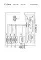
- FIG. 2illustrates a telephone system 200 implemented in accordance with one exemplary embodiment of the present invention.
- the telephone system 200includes a plurality of telephone networks 210 , 211 which are coupled together by a fiber optic connection 32 .
- the first telephone network 210is illustrated in detail in FIG. 2 .
- the second telephone network 211may be the same as the first telephone network 210 or, e.g., a known telephone network, e.g., the network 10 of FIG. 1 . While two telephone networks are shown in the FIG. 2 embodiment, it is to be understood that the system may comprise any number of networks 210 , 211 and/or other additional communications networks which provide, e.g., Internet services.
- the telephone network 210includes a plurality of telephones 212 , 214 , a C.O. switch 216 , a first voice mail IP 228 , a second voice mail IP 230 , a control IP 232 and a switching matrix 234 .
- the telephones 212 , 214are coupled to the central office switch 216 via a first interface 218 .
- Each telephone 212 , 214corresponds to a telephone subscriber who, in addition to subscribing to basic telephone service may also subscribe to one or more additional services such as voice mail and/or voice dialing services provided though the use of IPs 228 , 230 , 232 .
- the switch's interface 218is coupled by a local bus to a CPU 220 , memory 222 , digit receiver 226 and a second interface 224 .
- the CPU 220controls call routing and other switch operations in response to inputs received via the first and second interfaces 218 , 224 in accordance with program routines stored in the memory 222 .
- the digit receiver 226when active, detects the receipt of DTMF tones and converts them to digits which are supplied to the CPU 220 for, e.g., call routing purposes.
- the switch 216is capable of implementing the known NFA protocol for communicating between one or more of the telephones 212 , 214 coupled thereto and one or more of the IPs 228 , 230 , 232 .
- the switch 216is a Class V digital communications switch.
- the switch 216is coupled to each one of the first and second voice mail IPs 228 , 230 via its second interface 224 , and one or more T 1 links and SMDI lines.
- a voice and/or data connectioncan be established between a subscriber operating one of the telephones 212 , 214 and either the first or second voice mail IPs 228 , 230 using one of the T 1 links.
- the SMDI links between the voice mail IPs 228 , 230 and the C.O. switch 216are used to notify the central office switch when a new message has been received and is waiting for a particular subscriber corresponding to one of the telephones 212 , 214 coupled to the central office switch.
- the central office switchuses the SMDI information to activate a message waiting light on the particular subscriber's telephone 212 , 214 , when such message waiting functionality is supported by the telephone 212 , 214 .
- the SMDI lines of the first and second voice mail IPs 228 , 230are also coupled to SMDI inputs of the control IP 232 .
- the control IP 232receives information regarding messages which are waiting for a voice mail subscriber at the voice mail IPs, 228 , 230 .
- the control IP 232is coupled to the C.O. switch 216 by a recent change channel (RCC) and a plurality of T 1 links.
- the T 1 linksare routed through the switching matrix 234 .
- the switching matrix 234is controlled by a switching control signal (SCS) received from to the control IP 232 .
- SCSswitching control signal
- the control IP 232can control the routing of incoming and outgoing lines to establish a connection to anyone of a plurality of line termination points including the first and second voice mail IPs 228 , 230 and telephones 212 , 214 .
- the switching matrix 234may be replaced by a programmable switch such as those made by the Summa Four Corporation.
- FIG. 3Aillustrates a control IP 300 suitable for use as the control IP 232 of the system 200 .
- the control IP 300may be used to support voice dialing services in addition to switch and call routing control functions.
- the control IP 300comprises a plurality of speech recognizer arrays, 302 , 304 , 306 , a control interface 308 , and an application processor 312 .
- Each of the speech recognizer circuits 302is coupled to at least one T 1 link for receiving and transmitting voice and data to and from the switch 216 .
- Each of the speech recognizer arrays 302 , 304 , 306is also coupled to an interface 318 of the application processor 312 .
- the application processor 312includes the interface 318 , a CPU 314 , and a plurality of data storage devices including a memory 316 , a database 310 , and service logic 311 .
- the memory 316stores instructions in the form of a program as well as data about the speech recognizer arrays 302 , 304 , 306 and the speech recognition capabilities of various circuits included therein.
- the service logicincludes data and program code used to implement one or more services, e.g., a voice dialing service.
- the program stored in the memory 316in conjunction with the information and program code stored in the service logic 311 , when executed by the CPU 314 , controls the operation of the control IP in accordance with the present invention.
- the interface 318is used to couple and interface the various components of the application processor, such as the database 310 , CPU 314 , memory 316 and service logic 311 to the speech recognizer arrays 302 , 304 , 306 and the control interface 308 .
- the interface 318converts the various signals received by the application processor 312 into a format that can be interpreted and processed by the CPU 314 as well as converts signals generated by the CPU 314 into a signal format that can be used to control and interact with the various circuits coupled to the application processor 312 .
- the control interface 308is responsible for receiving SMDI signal inputs from the voice mail IPs 228 , 230 which form part of the network 210 .
- the information regarding waiting messages, e.g., subscriber's account number and message waiting indicator, received via the SMDI links,is conveyed to the application processor 312 .
- the application processor 312is responsive to the information received via the SMDI links which it uses in conjunction with information from the database 310 to determine the action which is to be taken by the control ⁇ P 300 .
- the application processorcan instruct; e.g., using the recent change channel (RCC), the C.O.
- the application processor 312can control the switching matrix 234 to establish connections via the C.O. switch with one or more IPs and/or destination telephones.
- the database 310which is included in the application processor 312 , is used to store relevant subscriber information.
- FIG. 3Billustrates an exemplary control IP database 310 .
- the database 310comprises a plurality of entries.
- One set of entriesrepresented by a horizontal row, is associated with each subscriber being serviced by the control IP 232 .
- Each set of entriesincludes information pertinent to servicing one subscription which, in most cases, will correspond to a single individual subscriber. However, in the case of a multi-party mailbox, the single subscription may correspond to multiple individuals.
- columns 1 - 9represent different information entries which are maintained in the database 310 for each subscription.
- Column 1corresponds to subscriber name information
- column 2corresponds to a subscriber ID number.
- the subscriber ID numbermay be, e.g., a number used to identify the subscriber for voice mail purposes.
- Column 3corresponds to subscriber telephone number information.
- the telephone number informationmay be used, e.g., to identify to the C.O. switch 216 , the line on which the NFA protocol is to be enabled/disabled.
- control IP 232can identify the particular subscriber for which a message is waiting by using the received telephone number and the telephone number information stored in the database 310 .
- Column 4 of the database 310corresponds to the subscriber's personal identification number (PIN) which the subscriber would normally use to access the messaging service or services to which the subscriber subscribes.
- PINpersonal identification number
- Columns 5 , 6 , 7 , and 8include status and service information used by the IP 232 in determining how to control call routing, e.g., which IPs a customer should be connected to, and what services are to be provided to a customer.
- NFA protocol statuscorresponds to NFA protocol status. If the NFA protocol is enabled for a particular subscriber, the subscriber will automatically be coupled to the control IP 232 when the C.O. switch detects an off-hook condition on the subscriber's line.
- the NFA protocolis not enabled for a particular subscriber, that subscriber will not be automatically connected to the control IP when an off-hook condition is initiated. Under such circumstances, the subscriber would have to dial the number of an IP to gain access to his or her voice mail service or other IP provided service.
- Database column 6corresponds to message waiting status. If a message is waiting for a particular subscriber, e.g., as indicated by the receipt of an SMDI signal including the subscriber's telephone number, this column will include an IP identifier identifying the IP where a message is waiting. In the event that messages are waiting on multiple IPs for a subscriber, the entry in column 6 associated with the subscriber will include an IP identifier for each IP with a waiting message.
- Database column 7indicates the type of message prompt to be played to the subscriber once a connection is established between the subscriber and the control is.
- a message that there are no waiting messagesis played to the subscriber in the event that the subscriber connects to the control IP, e.g. by dialing the IP.
- “NONE”is indicated with regard to the prompt that should be used for subscribers without waiting messages.
- a voice messageis waiting for an individual subscriber to an individual voice mail service
- default messageis played to the subscriber upon connection to the IP.
- the default messagemay be something like “You have at least one new message.” In at least one embodiment the default message provides a user with the actual number of new waiting messages.
- a prompt identifying the individual for whom the waiting message is intendedmay be played when such information is available.
- the prompt which is playedstates: “NEW MESSAGE FOR: NAME” where NAME is the name of the individual to whom the waiting message is directed.
- NAMEis the name of the individual to whom the waiting message is directed.
- Column 8indicates whether the customer subscribes to a Voice Dialing service supported by the control IP 232 . As will be discussed below, this information is important with regard to call flow handling by the control IP 232 . Normally, for voice dialing service subscribers, the NFA protocol feature will be enabled at the central office switch 216 even when messages are not waiting for the subscriber. This allows the subscriber to obtain direct access to the voice dialing capability of the control IP without having to dial the IP.
- the NFA protocol featureis disabled in accordance with the present invention at the C.O. switch when there are no messages waiting for the subscriber.
- Column 9includes voice template and voice recording information (TR) used for supporting voice dialing services for subscribers to the voice dialing service.
- TRvoice recording information
- a telephone number, to be dialed,is also normally stored in the database 310 for each name for which there is a stored template.
- columns 5 - 9 of the first row of database 310indicate, for example, that the NFA protocol is not enabled for his telephone line, that there are no messages waiting for him, that a prompt is to be played to John Smith indicating that there are no waiting messages in the event that he establishes a connection with the control IP, e.g., via a direct dial operation, that he does not subscribe to the control IP's voice dialing service, and that there are no stored templates or recordings for John Smith.
- columns 5 - 9 of the second row of database 310indicate, for example, that the NFA protocol is enabled for her telephone line, that there is one or more messages waiting for her on the first voice mail IP 228 , that a default prompt is to be played to her indicating that there are one or more waiting messages in the event that she establishes a connection with the control IP, e.g., via initiating an off-hook condition on the telephone line identified by the telephone number listed in database 310 , that she does not subscribe to the control IP's voice dialing service, and that there are no stored templates or recordings for her.
- FIG. 4illustrates a speech recognizer array 400 suitable for use as any one of the speech recognizer arrays 302 , 304 , 306 .
- the speech recognizer array 400includes a T 1 interface for coupling the recognizer array to a T 1 link, first and second speaker independent speech recognition circuits 404 , 406 , a primary speech recognizer 407 and a DTMF tone generator/receiver 410 .
- These circuits 402 , 404 , 406 , 407 , 410are coupled together by a data bus 403 and a high bandwidth bus 401 capable of carrying voice communications.
- the high bandwidth bus 401is also coupled to the control IP's application processor 312 .
- the data bus 403couples a CPU 412 , memory 414 and an Ethernet adapter 416 to the data bus 403 thereby allowing them to interact with the various speech recognition circuits 404 , 406 , 408 , T 1 interface 402 and DTMF tone generator/receiver 410 .
- the Ethernet adapter 416is used to couple the data bus 403 to the application processor 312 .
- the primary speech recognizer 407includes a speech capture circuit 409 and a combined speaker independent and speaker dependent speech recognition circuit 408 .
- the speech capture circuit 409is used to collect speech data and to arrange it into segments which are then supplied to one of the speech recognition circuits 404 , 406 or 408 for processing.
- the speech capture circuit 409can transmit captured speech to any of the voice recognition circuits 404 , 406 , 408 thereby eliminating the need to provide a separate speech capture circuit 409 for each of the speech recognition circuits 404 , 406 , 408 .
- Each of the speech recognition units 404 , 406 , 408include a processor and memory which are used to perform speech recognition operations.
- the large vocabulary speaker independent speech recognition circuit 404may support, e.g., the recognition of, e.g., over 100 words or phrases using speaker independent speech recognition techniques.
- the combined speaker independent and speaker dependent speech recognition circuitmay support, e.g., the recognition of 20-75 words or phrases.
- the small vocabulary speaker independent speech recognition circuitmay support the recognition of 20 or fewer words, e.g., spoken numbers or keywords, which may be included in phrases.
- the large vocabulary recognition circuit 406will normally be implemented using a relatively powerful CPU and a large amount of memory.
- the combined speaker independent and speaker dependent speech recognition circuit 408will normally be implemented using a less powerful CPU and less memory than the speech recognizer 406 while the small vocabulary speaker independent speech recognition circuit 404 will normally be implemented using the least amount of memory and the least powerful CPU out of the three speech recognition circuits 404 , 406 , 408 .
- the recognition circuit 404uses the least powerful CPU and least memory because it needs to perform the least processing operations per unit time, out of the three recognizer circuits, for each caller being serviced to perform real time speech recognition.
- the large vocabulary recognition circuit 406has to perform the most processing operations, out of the three circuits 404 , 406 , 408 , per caller per unit time, to perform real time speech recognition and therefore includes the most powerful CPU out of the speech recognition circuits 404 , 406 , 408 .
- the large vocabulary speaker independent speech recognition circuit 406is capable is capable of detecting a large number of names and phrases using speaker independent speech recognition techniques. For this reason, it is particularly well suited for, e.g., providing corporate directory information where it is desirable to be able to identify hundreds or even thousands of names of individual people and words which are, e.g., part of the name of a corporate department title.
- the large vocabulary speech recognition circuit 406may be thought of as a high end, e.g., relatively expensive and powerful, speech recognition circuit.
- the small vocabulary speaker independent speech recognition circuit 404supports the recognition of relatively few words or phrases, e.g., less than 20.
- the circuit 404is used to recognize numbers spoken as part of a phrase such as “press number”.
- itis used to recognize words which may be interpreted as a trigger to switch to the use of another voice dialing circuit.
- the combined speaker independent and speaker dependent speech recognition circuit 408may be characterized as a mid-level speech recognition circuit capable of recognizing, e.g., up to 100 words or phrases in one exemplary embodiment.
- the circuit 408is particularly well suited for voice dialing purposes and may be the same as or similar to the speech recognition circuit described at length in U.S. Pat. No. 5,719,921 which is hereby expressly incorporated by reference.
- the combined speaker independent and speaker dependent speech recognition circuit 408is used, in one embodiment, to support voice dialing.
- Voice dialinggenerally involves performing speaker independent speech recognition used to identify commands, e.g., dial, forward, cancel call forward, and speaker dependent speech recognition to identify names, e.g., the names of the people to be called. See, U.S. Pat. No. 5,719,921 for a discussion of the use of speaker independent and speaker dependent speech recognition to support voice dialing services.
- speaker dependent speech recognition templatese.g., of names are stored in the database 310 for each voice dialing service subscriber. This information is retrieved, stored in the memory of the speech recognition circuit 408 , and used to support voice dialing, when a connection is established between the control IP 232 and a voice dialing service subscriber.
- the speech recognition circuit 404 , 406 , 408 which is used to support speech recognitionis dynamically changed according to the speech recognition task to be performed during the particular stage of a call.
- hardwareis used in a more cost effective manner than would be possible if an unnecessarily powerful, and therefore, relatively expensive, speech recognition circuit were used for all stages of call processing.
- the combined speaker independent and speaker dependent speech recognition circuit 408is used during portions of a call where voice dialing is to be provided.
- the small vocabulary speaker independent speech recognition circuit 404is used during portions of a call where the detection of, e.g., spoken digits alone or as part of a phrase.
- circuit 406is used.
- the dynamic switching between speech recognition units 404 , 406 , 408 , as a call progresses and/or the service being provided the subscriber changes during a callis performed under control of the application processor 312 and/or CPU 412 .
- a service codee.g., a number indicating voice dialing, corporate directory, or a voice mail service request
- a new service codemay be supplied to the control IP during the same call connection, e.g., in response to the switch detecting the pressing of the * key followed by a number indicating a requested service such as voice mail service.
- CPU 412 of the speech recognizer arraydetects the service code associated with a particular call connection and assigns one of the speech recognizer circuits 408 , 406 , 404 to service the call as a function of the service code. In the event that another service code is received during the same call connection, the CPU will re-assess the speech recognition circuit assignment in response to receipt of the new service code.
- the speech recognizer assigned to service a callmay be dynamically changed during the call. For example, if a voice dialing service code is initially received, the combined speaker independent and speaker dependent speech recognition circuit 408 would be assigned to service the call. If during the call a voice message service code were received, the CPU 412 would de-assign the combined speech recognizer and assign the small vocabulary speaker independent speech recognition to servicing the call.
- the call connection established with the control IP 232is monitored throughout the period in which the call connection is maintained for spoken words or phrases, referred to herein as “trigger phrases” which may be used to determine the service to be performed and thus which speech recognizer is best suited for servicing a particular portion of a call.
- trigger phrasesFor example, detection of the phrase “corporate directory” would be interpreted as indicative of a corporate directory information request and, in response to detection of such a phrase, the large vocabulary recognition circuit 406 would be assigned to service the call. Detection of the word “DIAL” or a spoken name included in the caller's voice dialing database could be interpreted as indicating a voice dialing service request. In such an instance the combined speech recognition circuit 408 would be assigned to service the call. Similarly, the phrase “voice mail” would trigger use of the small vocabulary speech recognition circuit 404 to service the call.
- Each of the speech recognition circuits 404 , 406 , 408can use speaker independent speech recognition techniques to detect such keywords or trigger phrases. Accordingly, such keywords or trigger phrases can be detected at any point during a call causing the CPU 412 to reassess and possibly re-assign the call to a different one of the speech recognition circuits 404 , 406 , 408 . In this manner the CPU 412 matches the requested service to the most cost effective one of the speech recognition circuits available.
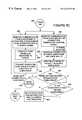
- FIGS. 5A-5Care a flow diagram illustrating the operations performed by the control IP in servicing a subscriber.
- control IPOperation of the control IP begins in step 502 , the START step.
- the control IP's application processor 312is initialized, the IP control program stored in the memory 316 is loaded and executed by the CPU 314 .
- control IP operationproceeds to step 504 .
- the application processor 312via the speech recognizer arrays 303 , 304 , 306 and control interface 308 , monitors for inputs to the control IP, (e.g.) from either the SMDI lines or T 1 links coupled to the control IP 232 .
- step 506a determination is made by the application processor as to whether or not an input has been detected. If no input has been detected operation proceeds once again to the monitoring step 504 . If, however, in step 506 , a message waiting indicator signal is detected, e.g., on one of the SMDI lines, operation progresses to step 508 .
- step 508the subscriber for which the message is intended is identified. This is accomplished by, e.g., using either a telephone number or subscriber ID received from the SMDI line in conjunction with a message waiting signal, with the corresponding subscriber information stored in the database 310 . Once the subscriber for which the message is intended is identified, and the corresponding data base entries for the subscriber retrieved from the database 310 , operation proceeds to step 510 .
- step 510a determination is made, e.g., from the data included in column 5 of the database 310 , as to whether or not the NFA protocol is active at the C.O. switch for the identified subscriber for which the message is intended.
- Active NFA protocol status at the switch for the identified subscriberwill result in the identified subscriber being coupled automatically to the control IP 232 in response to the detection of an off-hook condition on the identified subscriber's line.
- the NFA protocolwill be active for the identified subscriber as the result of the earlier unretrieved waiting messages. Similarly, if the subscriber subscribes to the voice dialing service supported by the control IP 232 , the NFA protocol will be enabled for the subscriber.
- step 510If, in step 510 it is determined that the NFA protocol is already active for the identified subscriber, operation proceeds directly to step 514 .
- step 510it is determined that the NFA protocol is not active for the subscriber at the C.O. switch operator proceeds to step 512 wherein a control signal is sent by the control IP to the C.O. switch, via the recent change channel (RCC).
- the control signalinstructs the C.O. switch to connect the identified subscriber to the control I.P., in response to an off-hook condition on the identified subscriber's telephone line, e.g., by using the NFA protocol.
- step 514operation progresses to step 514 .
- Step 514involves updating of the database 310 to reflect changes in the status information associated with the identified subscriber. This involves, e.g., changing the NFA status information if it was activated in step 512 , and updating the message waiting and message prompt information to reflect the waiting message. For example, the message waiting status information in col. 6 may be updated to reflect that there is an additional waiting message for the identified subscriber and the VMIP where the message is waiting. In addition, the message prompt information, included in database column 7 , will be modified, if necessary, so that the identified subscriber will be informed of the waiting message upon connecting to the control IP.
- step 514operation returns to the monitoring step 504 wherein the control IP monitors for additional inputs. From step 504 , operation proceeds to step 506 .
- step 506If, in step 506 , a subscriber connection signal is detected as a result of the monitoring for received signals which occurred in step 504 , operation proceeds to step 520 via flow chart connectors 516 , 518 .
- the subscriber connection signalwill normally include information sufficient to identify the subscriber for database access purposes, e.g., the subscriber's telephone number or account number information.
- the exemplary individual subscriber who established the connection to the IPwill be referred to as “the connected subscriber”.
- step 520the database 310 is accessed and the information included therein, pertinent to the connected subscriber, is retrieved.
- the retrieved informationmay include, e.g., in the case where the caller is a voice dialing service subscriber, speaker dependent voice dialing templates and recordings in addition to the other information illustrated in FIG. 3 B.
- step 522a determination is made, using the retrieved information, as to whether the connected subscriber is a voice dialing subscriber. If the answer to this inquiry is yes, operation proceeds to step 524 wherein the voice dialing service is provided to the caller.
- This stepinvolves, e.g., loading retrieved speaker dependent speech recognition templates and recordings into the speech recognition circuit 408 . It also involves controlling the recognition circuit 408 so that it monitors the line which connects the subscriber to the control IP and performs speech recognition operations on speech transmitted thereon.
- the speech recognition circuit 408receives an instruction to dial a telephone number over the line connecting the subscriber to the control IP 232 , a voice dialing operation will be performed by the IP in a manner that is the same as or similar to the manner in which known voice dialing service is provided.
- step 524operation proceeds to step 526 . Operation will proceed directly from step 522 to step 526 if in step 522 it is determined that the connected subscriber is not a voice dialing subscriber.
- step 526a determination is made from the retrieved database information, e.g., by the application processor 312 , as to whether there are any new messages waiting for the connected subscriber. If there are no new messages, operation proceeds to step 527 .
- step 527the caller is notified, e.g., via an audio prompt that there are no new messages.
- the connection between the IP and the subscriberis then allowed to terminate, in step 528 , in accordance with voice dialing procedures in the event a voice dialing call is placed or if the subscriber hangs up.
- a preselected amount of timemay be allowed to pass in step 527 before the no new messages prompt is played. If the subscriber initiates a voice dialing call during this period, the call will be allowed to terminate as a conventional voice dialing call without the prompt being played to the subscriber.
- step 526If, in step 526 it is determined that there are new messages for the subscriber, operation proceeds to step 530 .
- step 530the subscriber is notified of the presence of a waiting message, e.g., by playing the prompt indicated in the database 310 for the connected subscriber. From step 530 operation proceeds to step 531 wherein an inquiry is made as to whether or not the subscriber wants to retrieve the messages. The inquiry may involve playing of a message asking if the subscriber wants to retrieve the messages followed by monitoring of the call connection to detect a spoken YES or NO response.
- step 531If, in step 531 , a NO response is detected operation proceeds to step 528 wherein the call connection is allowed to terminate according to normal voice dialing procedure or NFA protocol operation.
- step 531If, in step 531 , a YES response is detected indicating that the subscriber wants to retrieve the waiting messages operation proceeds to step 532 .
- step 532the control IP establishes a connection between the subscriber and a voice mail IP where one or more messages are waiting for the subscriber.
- the voice mail IP 228 , 230 to which the subscriber is connectedis determined by the information in the database 310 which indicates which IP contains the subscriber's waiting message or messages.
- the control IPseizes a line of one of the T 1 links coupled to the control IP. In addition, it controls the switching matrix 234 to route the subscribers call, via the C.O. switch 216 , to the desired voice mail IP 228 , 230 . In this manner, the control IP 232 establishes a connection between the subscriber and the voice mail IP 228 or 230 while remaining connected to the line.
- control IPsupplies both the connected subscriber's account number and PIN number information to the voice mail IP thereby eliminating the need for the connected subscriber to enter this information.
- step 534voice dialing support is de-activated if it was enabled. Accordingly, by the end of step 536 , the relatively expensive combined speaker independent and speaker dependent speech recognition circuit 408 used for voice dialing is released from servicing the connected subscriber.
- the DTMF receiver of the central office switchis disable with regard to the connected subscriber, the connected subscriber is free to interact with the voice messaging IP through the use of DTMF or voice instructions without accidentally initiating a telephone call.
- control IP operationproceeds to steps 542 and 548 via connectors 538 , 540 .
- the path comprising steps 542 , 544 , 546represents speech recognition and DTMF generation functionality supported by the control IP 232 which is provided to facilitate subscriber interaction with a voice mail or other connected service IP.
- This functionalityis provided through the use of one of the speaker independent speech recognition circuits 404 , 406 and the DTMF tone generator/receiver 410 . While speaker independent recognition is used in the illustrated embodiment speaker dependent recognition may be used alone or in combination with speaker independent speech recognition
- Step 542involves monitoring the line connected to the subscriber for speech such as the instruction “press one” or “one” which is to be recognized and converted into DTMF tones.
- speech recognition circuits 404 or 406Upon one of the speech recognition circuits 404 or 406 detecting a spoken digit, e.g., as part of a phrase such as “press one”, a signal is sent to the DTMF tone generator circuit 410 instructing it to generate a DTMF tone corresponding to the detected digit.
- one or more DTMF tonesare generated in response to the speech recognized in step 542 .
- the generated DTMF tones 546are transmitted by the control IP 232 to the voice mail IP 228 or 230 to which the subscriber is connected.
- the line to the subscriberis muted while the tones are transmitted to the voice mail IP.
- the voice mail IPreceives the DTMF signals generated from the subscribers speech and can respond thereto without the subscriber having to enter the signals by pressing keys and without the subscriber having to listen to the tones.
- connectionis monitored for additional speech.
- the process of monitoring the connection to a voice mail IPwill continue for the duration of the connection to the voice mail IP. Accordingly, while connected to the voice mail IP 228 or 230 , the subscriber will have the opportunity to input responses or commands to the voice mail IP using speech as opposed to having to press keys of a telephone.
- step 548The path beginning with step 548 may occur in parallel with the path beginning with step 542 .
- step 548the connection between the subscriber and the voice mail IP 228 , 230 is monitored for a voice mail IP connection termination control signal e.g. from the voice mail IP or subscriber. Operation progresses to step 550 when a termination signal is detected.
- step 550the connection between the subscriber and the voice mail IP 228 , 230 is terminated. From step 550 operation proceeds to step 552 wherein the database 310 is updated to reflect the review of messages by the subscriber which were stored on the voice mail IP to which the subscriber was connected.
- step 554After termination of the connection with the voice mail IP 228 or 230 , a determination is made in step 554 as to whether or not there are new messages waiting for the subscriber on another voice mail IP.
- step 554If in step 554 , it is determined that there are additional new messages waiting for the subscriber, e.g., on a different voice IP, operation proceeds to step 524 thereby causing the subscriber to automatically be connected to the IP with the messages.
- step 554if it is determined that there are no more messages waiting for the connected subscriber, operation proceeds to step 558 wherein a determination is made as to whether or not the connected subscriber is a voice dialing subscriber. If the connected subscriber is a voice dialing subscriber, operation proceeds to step 560 wherein the voice dialing function of the control IP 232 is enabled by, e.g., re-connecting the combined speaker independent and speaker dependent speech recognition circuit 408 to the connected subscriber's line.
- the C.O. switch's digit receiver 226is also enabled in step 560 . Accordingly, the connected subscriber can complete a call to a spoken or dialed telephone number without the need to hang-up after receiving his or her messages. Under such circumstances, termination of the connection with the caller will occur in accordance with normal voice dialing procedures which may include the connected subscriber hanging up the telephone.
- a connected subscribercan terminate the call at any time by hanging up.
- Hanging upcauses the control IP 232 to terminate the subscriber's connection with any voice mail IP's which may exist at the time of call termination.
- the control IP 232updates the database 232 to reflect the retrieval of messages prior to call termination if, in fact, any messages where retrieved.
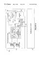
- FIG. 6illustrates a telephone system 600 implemented in accordance with another embodiment of the present invention.
- the system 600comprises a plurality of telephone networks 610 , 211 coupled together by a fiber optic line 32 .
- the telephone network 610comprises many of the same elements as the network 210 . Elements of the FIG. 2 and FIG. 6 embodiments which are the same, or similar, bear the same reference numbers and will not be described again.
- FIG. 2 and Fig, 6 embodimentsdiffer principally in the way in which the telephone network's peripheral devices, including first and second voice mail IPs 628 , 630 and a control IP 632 are connected together.
- SMDI linesare not used in the FIG. 6 embodiment as they are in the FIG. 2 embodiment.
- digital lines 631 , 633are used to connect the first and second voice mail IPs 631 , 633 to the control IP 632 .
- a brief message introductionmay be sent by the voice mail IP to the control IP 632 .
- the introductionmay include a 15 or 30 second sound message provided by a person leaving the message to identify him or herself.
- the information provided by the digital line 631 or 632may be a recording identifying the name of the recipient for which the message is intended.
- the control IP 632uses the lines 631 , 633 when establishing a connection between a connected caller and subscriber.
- the lines 631 , 633may be implemented using a plurality of digital data and/or control lines.
- the lines 631 , 632are implemented as lines which implement the known signaling system 7 (SS 7 ) protocol frequently used to implement telecommunications and data networks.
- SS 7signaling system 7
- control IPto facilitate the interaction of multiple IPs which provide services to the same subscriber
- voice mail embodimentit is to be understood, that the features of the present invention are applicable to facilitating subscriber/IP access and IP interaction regardless of the type or types of services being provided by the IPs.
- a low or mid level speech recognizer circuitsuch as the recognizer circuit 404 or 408 is used to service all or most of a call.
- an additional speech recognizersuch as the speech recognition circuit 406 is also assigned to service the call in conjunction with the other speech recognizer.
- speech recognition serviceis provided without having to use the large vocabulary speech recognizer for the entire duration of the call.
- speech recognition functionality included in the low or mid level speech recognizer circuitneed not be duplicated in the higher end speech recognition circuit which is switched in to supplement the speech recognition capability being provided.
Landscapes
- Engineering & Computer Science (AREA)
- Signal Processing (AREA)
- Telephonic Communication Services (AREA)
Abstract
Description
Claims (30)
Priority Applications (1)
| Application Number | Priority Date | Filing Date | Title |
|---|---|---|---|
| US09/082,551US6233315B1 (en) | 1998-05-21 | 1998-05-21 | Methods and apparatus for increasing the utility and interoperability of peripheral devices in communications systems |
Applications Claiming Priority (1)
| Application Number | Priority Date | Filing Date | Title |
|---|---|---|---|
| US09/082,551US6233315B1 (en) | 1998-05-21 | 1998-05-21 | Methods and apparatus for increasing the utility and interoperability of peripheral devices in communications systems |
Publications (1)
| Publication Number | Publication Date |
|---|---|
| US6233315B1true US6233315B1 (en) | 2001-05-15 |
Family
ID=22171904
Family Applications (1)
| Application Number | Title | Priority Date | Filing Date |
|---|---|---|---|
| US09/082,551Expired - LifetimeUS6233315B1 (en) | 1998-05-21 | 1998-05-21 | Methods and apparatus for increasing the utility and interoperability of peripheral devices in communications systems |
Country Status (1)
| Country | Link |
|---|---|
| US (1) | US6233315B1 (en) |
Cited By (56)
| Publication number | Priority date | Publication date | Assignee | Title |
|---|---|---|---|---|
| US6389118B1 (en)* | 1991-03-28 | 2002-05-14 | Edgar Martinez | Methods and apparatus for connecting a telephone subscriber to a peripheral device |
| EP1280327A1 (en)* | 2001-07-26 | 2003-01-29 | Siemens Aktiengesellschaft | Method of creating a telecommunication service in an intelligent network connecting at least a first and a second telecommunication terminal and system for realising such a service |
| US20030059004A1 (en)* | 2001-08-23 | 2003-03-27 | Jiang Doreen D. | System for synchronizing voice messaging subscriber information |
| US20030123631A1 (en)* | 2001-12-27 | 2003-07-03 | Moss John Wesley | Method and system for providing enhanced caller identfication information including total call control for all received calls |
| US6614885B2 (en)* | 1998-08-14 | 2003-09-02 | Intervoice Limited Partnership | System and method for operating a highly distributed interactive voice response system |
| US6643360B1 (en)* | 2000-01-31 | 2003-11-04 | Cisco Technology, Inc. | Check for pending e-mail using caller ID and selective answer ring |
| US20030228012A1 (en)* | 2002-06-06 | 2003-12-11 | Williams L. Lloyd | Method and apparatus for efficient use of voice trunks for accessing a service resource in the PSTN |
| US6721415B1 (en)* | 2000-02-17 | 2004-04-13 | Bellsouth Intellectual Property Corporation | Telephone voice messaging system and method using off-hook immediate trigger |
| US20040086094A1 (en)* | 2002-11-06 | 2004-05-06 | Bosik Barry S. | Method of providing personal event notification during call setup |
| US6782089B1 (en) | 1999-02-26 | 2004-08-24 | Avaya Technology Corp. | Bookmark system and method within an intelligent network |
| US6810034B1 (en) | 1999-02-26 | 2004-10-26 | Avaya Technology Corp. | Automatic conversion of telephone number to internet protocol address |
| US20050148324A1 (en)* | 1997-09-26 | 2005-07-07 | Henderson Daniel A. | Method and apparatus for an improved call interrupt feature in a cordless telephone answering device |
| US6925159B1 (en) | 1999-02-26 | 2005-08-02 | Avaya Technology Corp. | System and method of billing a predetermined telephone line for service utilized by a calling party |
| US20050281394A1 (en)* | 1998-09-11 | 2005-12-22 | Sbc Properties, L.P. | System and method for providing visual indication of caller and telephony platform information on customer premises equipment |
| US6999564B1 (en) | 2002-03-29 | 2006-02-14 | Nortel Networks Limited | System and method for telephonic switching and signaling based on voice recognition |
| US7010111B1 (en) | 1999-02-26 | 2006-03-07 | Avaya Technology Corp. | Audible confirmation using text to speech conversion |
| US7012998B1 (en)* | 1999-02-26 | 2006-03-14 | Avaya Technology Corp. | Voice messaging platform as an intelligent peripheral |
| US7116764B1 (en)* | 2000-08-11 | 2006-10-03 | Unisys Corporation | Network interface unit having an embedded services processor |
| US20060281471A1 (en)* | 2005-06-08 | 2006-12-14 | Cisco Technology,Inc. | Method and system for communicating using position information |
| US20070036118A1 (en)* | 2005-08-10 | 2007-02-15 | Cisco Technology, Inc. | Method and system for automatic configuration of virtual talk groups based on location of media sources |
| US20070037596A1 (en)* | 2005-08-10 | 2007-02-15 | Cisco Technology, Inc. | Method and system for providing interoperable communications with location information |
| US20070036100A1 (en)* | 2005-08-10 | 2007-02-15 | Cisco Technology, Inc. | Method and system for communicating media based on location of media source |
| US20070047479A1 (en)* | 2005-08-29 | 2007-03-01 | Cisco Technology, Inc. | Method and system for conveying media source location information |
| US20070104121A1 (en)* | 2005-11-04 | 2007-05-10 | Cisco Technology, Inc. | Method and system for providing a push-to-talk communication session |
| US20070105578A1 (en)* | 2005-11-04 | 2007-05-10 | Cisco Technology, Inc. | Method and system for providing a push-to-talk communication session using a control endpoint |
| US20070105579A1 (en)* | 2005-11-04 | 2007-05-10 | Cisco Technology, Inc. | Method and system for providing a proxy media service |
| US20070127652A1 (en)* | 2005-12-01 | 2007-06-07 | Divine Abha S | Method and system for processing calls |
| US7251318B1 (en)* | 1994-01-05 | 2007-07-31 | Intellect Wireless Inc. | Method and apparatus for improved personal communication devices and systems |
| US7257210B1 (en) | 1994-01-05 | 2007-08-14 | Intellect Wireless Inc. | Picture phone with caller id |
| US20070202907A1 (en)* | 2006-02-27 | 2007-08-30 | Cisco Technology, Inc. | Method and system for providing interoperable communications with congestion management |
| US20070202908A1 (en)* | 2006-02-28 | 2007-08-30 | Cisco Technology, Inc. | Method and system for providing interoperable communications with dynamic event area allocation |
| US20070206747A1 (en)* | 2006-03-01 | 2007-09-06 | Carol Gruchala | System and method for performing call screening |
| US20070226310A1 (en)* | 2006-03-24 | 2007-09-27 | Cisco Technology, Inc. | Automatically providing announcements for a push-to-talk communication session |
| US20070239824A1 (en)* | 2006-04-05 | 2007-10-11 | Cisco Technology, Inc. | Method and system for managing virtual talk groups |
| US20070270172A1 (en)* | 2006-05-18 | 2007-11-22 | Yogesh Kalley | Providing Virtual Talk Group Communication Sessions In Accordance With Endpoint Resources |
| US20070274460A1 (en)* | 2006-05-10 | 2007-11-29 | Shmuel Shaffer | Providing Multiple Virtual Talk Group Communication Sessions |
| US20070280195A1 (en)* | 2006-06-02 | 2007-12-06 | Shmuel Shaffer | Method and System for Joining a Virtual Talk Group |
| US7327832B1 (en)* | 2000-08-11 | 2008-02-05 | Unisys Corporation | Adjunct processing of multi-media functions in a messaging system |
| US20080102869A1 (en)* | 2006-10-30 | 2008-05-01 | Shmuel Shaffer | Method and System For Providing Information About a Push-To-Talk Communication Session |
| US20080159128A1 (en)* | 2006-12-28 | 2008-07-03 | Cisco Technology, Inc. | Method and System for Providing Congestion Management within a Virtual Talk Group |
| US20080280637A1 (en)* | 2007-05-10 | 2008-11-13 | Cisco Technology, Inc. | Method and System for Handling Dynamic Incidents |
| US20100159977A1 (en)* | 2008-12-19 | 2010-06-24 | Cisco Technology, Inc. | System and Method for Providing Channel Configurations in a Communications Environment |
| US20100159975A1 (en)* | 2008-12-19 | 2010-06-24 | Cisco Technology, Inc. | System and Method for Providing a Trunked Radio and Gateway |
| US20100161727A1 (en)* | 2008-12-19 | 2010-06-24 | Cisco Technology, Inc. | System and Method for Accelerating a Wide Area Notification |
| US20100228859A1 (en)* | 2006-02-21 | 2010-09-09 | Baeckstroem Martin | Method and apparatus for providing access for a limited set of mobile stations to a restricted local access point |
| US20100246466A1 (en)* | 2009-03-25 | 2010-09-30 | Cisco Technology, Inc. | Multiplexing and Demultiplexing Radio Channels |
| US20110039560A1 (en)* | 2009-08-11 | 2011-02-17 | Cisco Technology, Inc. | System and method for providing access in a network environment |
| US20110119740A1 (en)* | 2009-11-16 | 2011-05-19 | Cisco Technology, Inc. | System and method for providing enterprise integration in a network environment |
| US20110151886A1 (en)* | 2009-12-21 | 2011-06-23 | Cisco Technology, Inc. | System and method for providing resource management in a network environment |
| US20110225238A1 (en)* | 2010-03-11 | 2011-09-15 | Cisco Technology, Inc. | System and method for providing data channel management in a network environment |
| US20110228673A1 (en)* | 2010-03-17 | 2011-09-22 | Cisco Technology, Inc. | System and method for providing rate control in a network environment |
| US8036364B1 (en)* | 2002-11-14 | 2011-10-11 | At&T Intellectual Property I, L.P. | Transfer function for messaging platform in public telephone system |
| US8570909B1 (en) | 2006-10-17 | 2013-10-29 | Cisco Technology, Inc. | Method and system for providing an indication of a communication |
| US9413666B2 (en) | 2013-10-02 | 2016-08-09 | Cisco Technology, Inc. | Reporting radio access network congestion information in a network sharing environment |
| CN105979061A (en)* | 2016-04-13 | 2016-09-28 | 邦彦技术股份有限公司 | Voice communication equipment and voice communication control method |
| US10142886B2 (en) | 2016-09-30 | 2018-11-27 | Cisco Technology, Inc. | System and method to facilitate group reporting of user equipment congestion information in a network environment |
Citations (60)
| Publication number | Priority date | Publication date | Assignee | Title |
|---|---|---|---|---|
| US4737976A (en) | 1985-09-03 | 1988-04-12 | Motorola, Inc. | Hands-free control system for a radiotelephone |
| US4747124A (en) | 1982-09-28 | 1988-05-24 | Opcom | PBX telephone call control system |
| US4757525A (en) | 1982-09-29 | 1988-07-12 | Vmx, Inc. | Electronic audio communications system with voice command features |
| US4763350A (en) | 1984-06-16 | 1988-08-09 | Alcatel, N.V. | Facility for detecting and converting dial information and control information for service features of a telephone switching system |
| US4827500A (en) | 1987-01-30 | 1989-05-02 | American Telephone And Telegraph Company, At&T Bell Laboratories | Automatic speech recognition to select among call destinations |
| US4853953A (en) | 1987-10-08 | 1989-08-01 | Nec Corporation | Voice controlled dialer with separate memories for any users and authorized users |
| US4864622A (en) | 1986-10-31 | 1989-09-05 | Sanyo Electric Co., Ltd. | Voice recognizing telephone |
| US4878240A (en) | 1988-01-25 | 1989-10-31 | Bell Communications Research, Inc. | Multi-service telephone switching system |
| US4879743A (en) | 1988-10-03 | 1989-11-07 | American Telephone And Telegraph Company | PBX and adjunct using multi-frequency tones for communication therebetween |
| US4908864A (en) | 1986-04-05 | 1990-03-13 | Sharp Kabushiki Kaisha | Voice recognition method and apparatus by updating reference patterns |
| US4914690A (en) | 1988-03-31 | 1990-04-03 | Nicollet Technologies, Inc. | Universal PBX interface |
| US4922538A (en) | 1987-02-10 | 1990-05-01 | British Telecommunications Public Limited Company | Multi-user speech recognition system |
| US4926462A (en) | 1988-02-24 | 1990-05-15 | Vmx/Opcom | Interface to and operation of a voice messaging system |
| US4926461A (en) | 1987-01-12 | 1990-05-15 | Code-A-Phone Corporation | Telephone answering machine having call transfer capabilities |
| US4928302A (en) | 1987-11-06 | 1990-05-22 | Ricoh Company, Ltd. | Voice actuated dialing apparatus |
| US4932042A (en) | 1989-03-03 | 1990-06-05 | At&T Bell Laboratories | Spontaneous voice and data messaging |
| US4945557A (en) | 1987-06-08 | 1990-07-31 | Ricoh Company, Ltd. | Voice activated dialing apparatus |
| US4961212A (en) | 1987-05-29 | 1990-10-02 | Kabushiki Kaisha Toshiba | Voice recognition system used in telephone apparatus |
| US4979206A (en) | 1987-07-10 | 1990-12-18 | At&T Bell Laboratories | Directory assistance systems |
| US5003584A (en) | 1990-04-16 | 1991-03-26 | At&T Bell Laboratories | Method and apparatus for the billing of value-added communication calls |
| US5007081A (en) | 1989-01-05 | 1991-04-09 | Origin Technology, Inc. | Speech activated telephone |
| US5036533A (en) | 1989-04-24 | 1991-07-30 | Messager Partners | System for providing automatic voice messaging in a digital network environment |
| US5042063A (en) | 1987-09-11 | 1991-08-20 | Kabushiki Kaisha Toshiba | Telephone apparatus with voice activated dialing function |
| US5046088A (en) | 1989-10-31 | 1991-09-03 | Dialogic Corporation | Converter for in-band routing and/or origination information |
| US5091947A (en) | 1987-06-04 | 1992-02-25 | Ricoh Company, Ltd. | Speech recognition method and apparatus |
| US5128982A (en) | 1989-07-31 | 1992-07-07 | Dugdale William P | Electronic apparatus for "Hands off" control of a voice mail system |
| US5148471A (en) | 1989-11-20 | 1992-09-15 | Motorola, Inc. | Communications device with voice recognition and movable element control interface |
| US5150399A (en) | 1990-08-27 | 1992-09-22 | Telephonic Equipment Corporation | Public telephone interface and method of operating the same |
| US5165095A (en) | 1990-09-28 | 1992-11-17 | Texas Instruments Incorporated | Voice telephone dialing |
| US5181237A (en) | 1990-10-12 | 1993-01-19 | At&T Bell Laboratories | Automation of telephone operator assistance calls |
| US5297183A (en) | 1992-04-13 | 1994-03-22 | Vcs Industries, Inc. | Speech recognition system for electronic switches in a cellular telephone or personal communication network |
| US5315649A (en) | 1992-04-15 | 1994-05-24 | Vcs Industries, Inc. | Toll call telephone service center |
| US5319703A (en) | 1992-05-26 | 1994-06-07 | Vmx, Inc. | Apparatus and method for identifying speech and call-progression signals |
| US5325421A (en)* | 1992-08-24 | 1994-06-28 | At&T Bell Laboratories | Voice directed communications system platform |
| US5335261A (en) | 1990-11-30 | 1994-08-02 | Sony Corporation | Radio telephone apparatus |
| US5365574A (en) | 1990-05-15 | 1994-11-15 | Vcs Industries, Inc. | Telephone network voice recognition and verification using selectively-adjustable signal thresholds |
| US5369685A (en) | 1991-03-07 | 1994-11-29 | Sprint Communications Company L.P. | Voice-activated telephone directory and call placement system |
| US5371779A (en) | 1992-03-13 | 1994-12-06 | Nec Corporation | Call initiating system for mobile telephone units |
| US5375164A (en) | 1992-05-26 | 1994-12-20 | At&T Corp. | Multiple language capability in an interactive system |
| US5384833A (en) | 1988-04-27 | 1995-01-24 | British Telecommunications Public Limited Company | Voice-operated service |
| US5390278A (en) | 1991-10-08 | 1995-02-14 | Bell Canada | Phoneme based speech recognition |
| US5404422A (en) | 1989-12-28 | 1995-04-04 | Sharp Kabushiki Kaisha | Speech recognition system with neural network |
| US5406618A (en) | 1992-10-05 | 1995-04-11 | Phonemate, Inc. | Voice activated, handsfree telephone answering device |
| US5420912A (en) | 1993-02-27 | 1995-05-30 | Alcatel N.V. | Telephone having portable voice control module for playing back speech or performing a hands-free telephone function |
| US5425128A (en) | 1992-05-29 | 1995-06-13 | Sunquest Information Systems, Inc. | Automatic management system for speech recognition processes |
| US5428608A (en) | 1993-12-30 | 1995-06-27 | At&T Corp. | Call connection technique |
| US5452289A (en) | 1993-01-08 | 1995-09-19 | Multi-Tech Systems, Inc. | Computer-based multifunction personal communications system |
| US5457770A (en) | 1993-08-19 | 1995-10-10 | Kabushiki Kaisha Meidensha | Speaker independent speech recognition system and method using neural network and/or DP matching technique |
| US5463715A (en) | 1992-12-30 | 1995-10-31 | Innovation Technologies | Method and apparatus for speech generation from phonetic codes |
| US5463677A (en) | 1993-05-27 | 1995-10-31 | At&T Corp. | Method and apparatus for facilitating the making of collect calls |
| US5463685A (en) | 1992-04-01 | 1995-10-31 | At&T Ipm Corp. | Network based outbound call management |
| US5583920A (en)* | 1992-04-17 | 1996-12-10 | Bell Atlantic | Intelligent peripheral in video dial tone network |
| US5712903A (en)* | 1995-08-21 | 1998-01-27 | Bell Atlantic Network Services, Inc. | Split intelligent peripheral for broadband and narrowband services |
| US5715294A (en) | 1993-02-16 | 1998-02-03 | C & P Of Virginia | Common channeling signaling network maintenance and testing |
| US5719921A (en) | 1996-02-29 | 1998-02-17 | Nynex Science & Technology | Methods and apparatus for activating telephone services in response to speech |
| US5742905A (en)* | 1994-09-19 | 1998-04-21 | Bell Communications Research, Inc. | Personal communications internetworking |
| US6002750A (en)* | 1997-12-12 | 1999-12-14 | U S West, Inc. | Method and system for providing integrated wireline/wireless voice messaging service |
| US6061432A (en)* | 1997-12-23 | 2000-05-09 | Bell Atlantic Network Services, Inc. | Voice mail system for obtaining routing information from signaling nodes |
| US6069890A (en)* | 1996-06-26 | 2000-05-30 | Bell Atlantic Network Services, Inc. | Internet telephone service |
| US6088439A (en)* | 1997-07-22 | 2000-07-11 | Lucent Technologies Inc. | System for connecting calls on physically distinct servers on an advanced intelligent network |
- 1998
- 1998-05-21USUS09/082,551patent/US6233315B1/ennot_activeExpired - Lifetime
Patent Citations (61)
| Publication number | Priority date | Publication date | Assignee | Title |
|---|---|---|---|---|
| US4747124A (en) | 1982-09-28 | 1988-05-24 | Opcom | PBX telephone call control system |
| US4757525A (en) | 1982-09-29 | 1988-07-12 | Vmx, Inc. | Electronic audio communications system with voice command features |
| US4763350A (en) | 1984-06-16 | 1988-08-09 | Alcatel, N.V. | Facility for detecting and converting dial information and control information for service features of a telephone switching system |
| US4737976A (en) | 1985-09-03 | 1988-04-12 | Motorola, Inc. | Hands-free control system for a radiotelephone |
| US4908864A (en) | 1986-04-05 | 1990-03-13 | Sharp Kabushiki Kaisha | Voice recognition method and apparatus by updating reference patterns |
| US4864622A (en) | 1986-10-31 | 1989-09-05 | Sanyo Electric Co., Ltd. | Voice recognizing telephone |
| US4926461A (en) | 1987-01-12 | 1990-05-15 | Code-A-Phone Corporation | Telephone answering machine having call transfer capabilities |
| US4827500A (en) | 1987-01-30 | 1989-05-02 | American Telephone And Telegraph Company, At&T Bell Laboratories | Automatic speech recognition to select among call destinations |
| US4922538A (en) | 1987-02-10 | 1990-05-01 | British Telecommunications Public Limited Company | Multi-user speech recognition system |
| US4961212A (en) | 1987-05-29 | 1990-10-02 | Kabushiki Kaisha Toshiba | Voice recognition system used in telephone apparatus |
| US5091947A (en) | 1987-06-04 | 1992-02-25 | Ricoh Company, Ltd. | Speech recognition method and apparatus |
| US4945557A (en) | 1987-06-08 | 1990-07-31 | Ricoh Company, Ltd. | Voice activated dialing apparatus |
| US4979206A (en) | 1987-07-10 | 1990-12-18 | At&T Bell Laboratories | Directory assistance systems |
| US5054053A (en) | 1987-09-11 | 1991-10-01 | Kabushiki Kaisha Toshiba | Speech recognition system for telephony |
| US5042063A (en) | 1987-09-11 | 1991-08-20 | Kabushiki Kaisha Toshiba | Telephone apparatus with voice activated dialing function |
| US4853953A (en) | 1987-10-08 | 1989-08-01 | Nec Corporation | Voice controlled dialer with separate memories for any users and authorized users |
| US4928302A (en) | 1987-11-06 | 1990-05-22 | Ricoh Company, Ltd. | Voice actuated dialing apparatus |
| US4878240A (en) | 1988-01-25 | 1989-10-31 | Bell Communications Research, Inc. | Multi-service telephone switching system |
| US4926462A (en) | 1988-02-24 | 1990-05-15 | Vmx/Opcom | Interface to and operation of a voice messaging system |
| US4914690A (en) | 1988-03-31 | 1990-04-03 | Nicollet Technologies, Inc. | Universal PBX interface |
| US5384833A (en) | 1988-04-27 | 1995-01-24 | British Telecommunications Public Limited Company | Voice-operated service |
| US4879743A (en) | 1988-10-03 | 1989-11-07 | American Telephone And Telegraph Company | PBX and adjunct using multi-frequency tones for communication therebetween |
| US5007081A (en) | 1989-01-05 | 1991-04-09 | Origin Technology, Inc. | Speech activated telephone |
| US4932042A (en) | 1989-03-03 | 1990-06-05 | At&T Bell Laboratories | Spontaneous voice and data messaging |
| US5036533A (en) | 1989-04-24 | 1991-07-30 | Messager Partners | System for providing automatic voice messaging in a digital network environment |
| US5128982A (en) | 1989-07-31 | 1992-07-07 | Dugdale William P | Electronic apparatus for "Hands off" control of a voice mail system |
| US5046088A (en) | 1989-10-31 | 1991-09-03 | Dialogic Corporation | Converter for in-band routing and/or origination information |
| US5148471A (en) | 1989-11-20 | 1992-09-15 | Motorola, Inc. | Communications device with voice recognition and movable element control interface |
| US5404422A (en) | 1989-12-28 | 1995-04-04 | Sharp Kabushiki Kaisha | Speech recognition system with neural network |
| US5003584A (en) | 1990-04-16 | 1991-03-26 | At&T Bell Laboratories | Method and apparatus for the billing of value-added communication calls |
| US5365574A (en) | 1990-05-15 | 1994-11-15 | Vcs Industries, Inc. | Telephone network voice recognition and verification using selectively-adjustable signal thresholds |
| US5150399A (en) | 1990-08-27 | 1992-09-22 | Telephonic Equipment Corporation | Public telephone interface and method of operating the same |
| US5165095A (en) | 1990-09-28 | 1992-11-17 | Texas Instruments Incorporated | Voice telephone dialing |
| US5181237A (en) | 1990-10-12 | 1993-01-19 | At&T Bell Laboratories | Automation of telephone operator assistance calls |
| US5335261A (en) | 1990-11-30 | 1994-08-02 | Sony Corporation | Radio telephone apparatus |
| US5369685A (en) | 1991-03-07 | 1994-11-29 | Sprint Communications Company L.P. | Voice-activated telephone directory and call placement system |
| US5390278A (en) | 1991-10-08 | 1995-02-14 | Bell Canada | Phoneme based speech recognition |
| US5371779A (en) | 1992-03-13 | 1994-12-06 | Nec Corporation | Call initiating system for mobile telephone units |
| US5463685A (en) | 1992-04-01 | 1995-10-31 | At&T Ipm Corp. | Network based outbound call management |
| US5297183A (en) | 1992-04-13 | 1994-03-22 | Vcs Industries, Inc. | Speech recognition system for electronic switches in a cellular telephone or personal communication network |
| US5315649A (en) | 1992-04-15 | 1994-05-24 | Vcs Industries, Inc. | Toll call telephone service center |
| US5583920A (en)* | 1992-04-17 | 1996-12-10 | Bell Atlantic | Intelligent peripheral in video dial tone network |
| US5319703A (en) | 1992-05-26 | 1994-06-07 | Vmx, Inc. | Apparatus and method for identifying speech and call-progression signals |
| US5375164A (en) | 1992-05-26 | 1994-12-20 | At&T Corp. | Multiple language capability in an interactive system |
| US5425128A (en) | 1992-05-29 | 1995-06-13 | Sunquest Information Systems, Inc. | Automatic management system for speech recognition processes |
| US5325421A (en)* | 1992-08-24 | 1994-06-28 | At&T Bell Laboratories | Voice directed communications system platform |
| US5406618A (en) | 1992-10-05 | 1995-04-11 | Phonemate, Inc. | Voice activated, handsfree telephone answering device |
| US5463715A (en) | 1992-12-30 | 1995-10-31 | Innovation Technologies | Method and apparatus for speech generation from phonetic codes |
| US5452289A (en) | 1993-01-08 | 1995-09-19 | Multi-Tech Systems, Inc. | Computer-based multifunction personal communications system |
| US5715294A (en) | 1993-02-16 | 1998-02-03 | C & P Of Virginia | Common channeling signaling network maintenance and testing |
| US5420912A (en) | 1993-02-27 | 1995-05-30 | Alcatel N.V. | Telephone having portable voice control module for playing back speech or performing a hands-free telephone function |
| US5463677A (en) | 1993-05-27 | 1995-10-31 | At&T Corp. | Method and apparatus for facilitating the making of collect calls |
| US5457770A (en) | 1993-08-19 | 1995-10-10 | Kabushiki Kaisha Meidensha | Speaker independent speech recognition system and method using neural network and/or DP matching technique |
| US5428608A (en) | 1993-12-30 | 1995-06-27 | At&T Corp. | Call connection technique |
| US5742905A (en)* | 1994-09-19 | 1998-04-21 | Bell Communications Research, Inc. | Personal communications internetworking |
| US5712903A (en)* | 1995-08-21 | 1998-01-27 | Bell Atlantic Network Services, Inc. | Split intelligent peripheral for broadband and narrowband services |
| US5719921A (en) | 1996-02-29 | 1998-02-17 | Nynex Science & Technology | Methods and apparatus for activating telephone services in response to speech |
| US6069890A (en)* | 1996-06-26 | 2000-05-30 | Bell Atlantic Network Services, Inc. | Internet telephone service |
| US6088439A (en)* | 1997-07-22 | 2000-07-11 | Lucent Technologies Inc. | System for connecting calls on physically distinct servers on an advanced intelligent network |
| US6002750A (en)* | 1997-12-12 | 1999-12-14 | U S West, Inc. | Method and system for providing integrated wireline/wireless voice messaging service |
| US6061432A (en)* | 1997-12-23 | 2000-05-09 | Bell Atlantic Network Services, Inc. | Voice mail system for obtaining routing information from signaling nodes |
Cited By (112)
| Publication number | Priority date | Publication date | Assignee | Title |
|---|---|---|---|---|
| US6389118B1 (en)* | 1991-03-28 | 2002-05-14 | Edgar Martinez | Methods and apparatus for connecting a telephone subscriber to a peripheral device |
| US7454000B1 (en) | 1994-01-05 | 2008-11-18 | Intellect Wireless, Inc. | Method and apparatus for improved personal communication devices and systems |
| US20070293204A1 (en)* | 1994-01-05 | 2007-12-20 | Henderson Daniel A | Method and apparatus for improved paging receiver and system |
| US7310416B1 (en) | 1994-01-05 | 2007-12-18 | Intellect Wireless Inc. | Method and apparatus for improved personal communication devices and systems |
| US7286658B1 (en) | 1994-01-05 | 2007-10-23 | Intellect Wireless Inc. | Method and apparatus for improved personal communication devices and systems |
| US20070275708A1 (en)* | 1994-01-05 | 2007-11-29 | Henderson Daniel A | Method and apparatus for improved personal communication devices and systems |
| US7426264B1 (en) | 1994-01-05 | 2008-09-16 | Henderson Daniel A | Method and apparatus for improved personal communication devices and systems |
| US20070293205A1 (en)* | 1994-01-05 | 2007-12-20 | Henderson Daniel A | Method and apparatus for improved personal communication devices and systems |
| US7308088B1 (en) | 1994-01-05 | 2007-12-11 | Intellect Wireless, Inc. | Method and apparatus for improved personal communication devices and systems |
| US7266186B1 (en) | 1994-01-05 | 2007-09-04 | Intellect Wireless Inc. | Method and apparatus for improved paging receiver and system |
| US7349532B2 (en) | 1994-01-05 | 2008-03-25 | Intellect Wireless Inc. | Picture and video message center system |
| US7257210B1 (en) | 1994-01-05 | 2007-08-14 | Intellect Wireless Inc. | Picture phone with caller id |
| US7305076B1 (en) | 1994-01-05 | 2007-12-04 | Intellect Wireless Inc. | Method and apparatus for improved paging receiver and system |
| US7254223B1 (en)* | 1994-01-05 | 2007-08-07 | Intellect Wireless Inc. | Method and apparatus for improved personal communication devices and systems |
| US7251318B1 (en)* | 1994-01-05 | 2007-07-31 | Intellect Wireless Inc. | Method and apparatus for improved personal communication devices and systems |
| US20050148324A1 (en)* | 1997-09-26 | 2005-07-07 | Henderson Daniel A. | Method and apparatus for an improved call interrupt feature in a cordless telephone answering device |
| US20030198321A1 (en)* | 1998-08-14 | 2003-10-23 | Polcyn Michael J. | System and method for operating a highly distributed interactive voice response system |
| US6614885B2 (en)* | 1998-08-14 | 2003-09-02 | Intervoice Limited Partnership | System and method for operating a highly distributed interactive voice response system |
| US7012996B2 (en) | 1998-08-14 | 2006-03-14 | Intervoice Limited Partnership | System and method for operating a highly distributed interactive voice response system |
| US7020250B2 (en)* | 1998-09-11 | 2006-03-28 | Sbc Properties, L.P. | System and method for providing visual indication of caller and telephony platform information on customer premises equipment |
| US20050281394A1 (en)* | 1998-09-11 | 2005-12-22 | Sbc Properties, L.P. | System and method for providing visual indication of caller and telephony platform information on customer premises equipment |
| US7466802B2 (en) | 1998-09-11 | 2008-12-16 | At&T Intellectual Property I, L.P. | System and method for providing visual indication of caller and telephony platform information on customer premises equipment |
| US6782089B1 (en) | 1999-02-26 | 2004-08-24 | Avaya Technology Corp. | Bookmark system and method within an intelligent network |
| US7010111B1 (en) | 1999-02-26 | 2006-03-07 | Avaya Technology Corp. | Audible confirmation using text to speech conversion |
| US6810034B1 (en) | 1999-02-26 | 2004-10-26 | Avaya Technology Corp. | Automatic conversion of telephone number to internet protocol address |
| US7012998B1 (en)* | 1999-02-26 | 2006-03-14 | Avaya Technology Corp. | Voice messaging platform as an intelligent peripheral |
| US6925159B1 (en) | 1999-02-26 | 2005-08-02 | Avaya Technology Corp. | System and method of billing a predetermined telephone line for service utilized by a calling party |
| US6643360B1 (en)* | 2000-01-31 | 2003-11-04 | Cisco Technology, Inc. | Check for pending e-mail using caller ID and selective answer ring |
| US6845150B1 (en) | 2000-01-31 | 2005-01-18 | Cisco Technology, Inc. | Check for pending e-mail using caller ID and selective answer ring |
| US7023978B2 (en) | 2000-02-17 | 2006-04-04 | Bellsouth Intellectual Property Corp. | Telephone voice messaging system and method using off-hook immediate trigger |
| US6721415B1 (en)* | 2000-02-17 | 2004-04-13 | Bellsouth Intellectual Property Corporation | Telephone voice messaging system and method using off-hook immediate trigger |
| US7327832B1 (en)* | 2000-08-11 | 2008-02-05 | Unisys Corporation | Adjunct processing of multi-media functions in a messaging system |
| US7116764B1 (en)* | 2000-08-11 | 2006-10-03 | Unisys Corporation | Network interface unit having an embedded services processor |
| EP1280327A1 (en)* | 2001-07-26 | 2003-01-29 | Siemens Aktiengesellschaft | Method of creating a telecommunication service in an intelligent network connecting at least a first and a second telecommunication terminal and system for realising such a service |
| WO2003010947A3 (en)* | 2001-07-26 | 2003-05-01 | Siemens Ag | Event-related automatic call set-up method |
| US7424494B2 (en)* | 2001-08-23 | 2008-09-09 | Comverse, Inc. | System for synchronizing voice messaging subscriber information |
| US20030059004A1 (en)* | 2001-08-23 | 2003-03-27 | Jiang Doreen D. | System for synchronizing voice messaging subscriber information |
| US20060133592A1 (en)* | 2001-12-27 | 2006-06-22 | Sbc Properties, Lp | Method and system for providing enhanced caller identification information including total call control for all received calls |
| US7580515B2 (en) | 2001-12-27 | 2009-08-25 | At&T Intellectual Property I, L.P. | Method and system for providing enhanced caller identification information including total call control for all received calls |
| US20070269026A1 (en)* | 2001-12-27 | 2007-11-22 | At&T Knowledge Ventures, Lp. | Method and system for providing enhanced caller identification information including total call control for all received calls |
| US7333599B2 (en) | 2001-12-27 | 2008-02-19 | At&T Knowledge Ventures, L.P. | Method and system for providing enhanced caller identification information including total call control for all received calls |
| US20030123631A1 (en)* | 2001-12-27 | 2003-07-03 | Moss John Wesley | Method and system for providing enhanced caller identfication information including total call control for all received calls |
| US6999564B1 (en) | 2002-03-29 | 2006-02-14 | Nortel Networks Limited | System and method for telephonic switching and signaling based on voice recognition |
| WO2003105497A1 (en)* | 2002-06-06 | 2003-12-18 | Revd Networks, Inc. | Method and apparatus for efficient use of voice trunks for accessing a service resource in the pstn |
| US20030228012A1 (en)* | 2002-06-06 | 2003-12-11 | Williams L. Lloyd | Method and apparatus for efficient use of voice trunks for accessing a service resource in the PSTN |
| US20040086094A1 (en)* | 2002-11-06 | 2004-05-06 | Bosik Barry S. | Method of providing personal event notification during call setup |
| US8036364B1 (en)* | 2002-11-14 | 2011-10-11 | At&T Intellectual Property I, L.P. | Transfer function for messaging platform in public telephone system |
| US20060281471A1 (en)* | 2005-06-08 | 2006-12-14 | Cisco Technology,Inc. | Method and system for communicating using position information |
| US8045998B2 (en) | 2005-06-08 | 2011-10-25 | Cisco Technology, Inc. | Method and system for communicating using position information |
| US20070037596A1 (en)* | 2005-08-10 | 2007-02-15 | Cisco Technology, Inc. | Method and system for providing interoperable communications with location information |
| US7706339B2 (en) | 2005-08-10 | 2010-04-27 | Cisco Technology, Inc. | Method and system for communicating media based on location of media source |
| US7633914B2 (en) | 2005-08-10 | 2009-12-15 | Cisco Technology, Inc. | Method and system for providing interoperable communications with location information |
| US20100197333A1 (en)* | 2005-08-10 | 2010-08-05 | Cisco Technology, Inc. | Method and System for Communicating Media Based on Location of Media Source |
| US8472418B2 (en) | 2005-08-10 | 2013-06-25 | Cisco Technology, Inc. | Method and system for communicating media based on location of media source |
| US7636339B2 (en) | 2005-08-10 | 2009-12-22 | Cisco Technology, Inc. | Method and system for automatic configuration of virtual talk groups based on location of media sources |
| US20070036100A1 (en)* | 2005-08-10 | 2007-02-15 | Cisco Technology, Inc. | Method and system for communicating media based on location of media source |
| US20070036118A1 (en)* | 2005-08-10 | 2007-02-15 | Cisco Technology, Inc. | Method and system for automatic configuration of virtual talk groups based on location of media sources |
| US7869386B2 (en) | 2005-08-29 | 2011-01-11 | Cisco Technology, Inc. | Method and system for conveying media source location information |
| US20070047479A1 (en)* | 2005-08-29 | 2007-03-01 | Cisco Technology, Inc. | Method and system for conveying media source location information |
| US7751348B2 (en) | 2005-11-04 | 2010-07-06 | Cisco Technology, Inc. | Method and system for providing a push-to-talk communication session |
| US20070105579A1 (en)* | 2005-11-04 | 2007-05-10 | Cisco Technology, Inc. | Method and system for providing a proxy media service |
| US8145249B2 (en) | 2005-11-04 | 2012-03-27 | Cisco Technology, Inc. | Method and system for providing a proxy media service |
| US20070105578A1 (en)* | 2005-11-04 | 2007-05-10 | Cisco Technology, Inc. | Method and system for providing a push-to-talk communication session using a control endpoint |
| US20070104121A1 (en)* | 2005-11-04 | 2007-05-10 | Cisco Technology, Inc. | Method and system for providing a push-to-talk communication session |
| US20070127652A1 (en)* | 2005-12-01 | 2007-06-07 | Divine Abha S | Method and system for processing calls |
| US20100228859A1 (en)* | 2006-02-21 | 2010-09-09 | Baeckstroem Martin | Method and apparatus for providing access for a limited set of mobile stations to a restricted local access point |
| US9420520B2 (en)* | 2006-02-21 | 2016-08-16 | Telefonaktiebolaget Lm Ericsson (Publ) | Method and apparatus for providing access for a limited set of mobile stations to a restricted local access point |
| US8085671B2 (en) | 2006-02-27 | 2011-12-27 | Cisco Technology, Inc. | Method and system for providing interoperable communications with congestion management |
| US20070202907A1 (en)* | 2006-02-27 | 2007-08-30 | Cisco Technology, Inc. | Method and system for providing interoperable communications with congestion management |
| US8260338B2 (en) | 2006-02-28 | 2012-09-04 | Cisco Technology, Inc. | Method and system for providing interoperable communications with dynamic event area allocation |
| US20070202908A1 (en)* | 2006-02-28 | 2007-08-30 | Cisco Technology, Inc. | Method and system for providing interoperable communications with dynamic event area allocation |
| US20070206747A1 (en)* | 2006-03-01 | 2007-09-06 | Carol Gruchala | System and method for performing call screening |
| US20070226310A1 (en)* | 2006-03-24 | 2007-09-27 | Cisco Technology, Inc. | Automatically providing announcements for a push-to-talk communication session |
| US7792899B2 (en)* | 2006-03-24 | 2010-09-07 | Cisco Technology, Inc. | Automatically providing announcements for a push-to-talk communication session |
| US20070239824A1 (en)* | 2006-04-05 | 2007-10-11 | Cisco Technology, Inc. | Method and system for managing virtual talk groups |
| US9112746B2 (en) | 2006-04-05 | 2015-08-18 | Cisco Technology, Inc. | Method and system for managing virtual talk groups |
| US7860070B2 (en) | 2006-05-10 | 2010-12-28 | Cisco Technology, Inc. | Providing multiple virtual talk group communication sessions |
| US20070274460A1 (en)* | 2006-05-10 | 2007-11-29 | Shmuel Shaffer | Providing Multiple Virtual Talk Group Communication Sessions |
| US7831270B2 (en) | 2006-05-18 | 2010-11-09 | Cisco Technology, Inc. | Providing virtual talk group communication sessions in accordance with endpoint resources |
| US20070270172A1 (en)* | 2006-05-18 | 2007-11-22 | Yogesh Kalley | Providing Virtual Talk Group Communication Sessions In Accordance With Endpoint Resources |
| US7639634B2 (en) | 2006-06-02 | 2009-12-29 | Cisco Technology, Inc. | Method and System for Joining a virtual talk group |
| US20070280195A1 (en)* | 2006-06-02 | 2007-12-06 | Shmuel Shaffer | Method and System for Joining a Virtual Talk Group |
| US8570909B1 (en) | 2006-10-17 | 2013-10-29 | Cisco Technology, Inc. | Method and system for providing an indication of a communication |
| US7809390B2 (en) | 2006-10-30 | 2010-10-05 | Cisco Technology, Inc. | Method and system for providing information about a push-to-talk communication session |
| US20080102869A1 (en)* | 2006-10-30 | 2008-05-01 | Shmuel Shaffer | Method and System For Providing Information About a Push-To-Talk Communication Session |
| US20080159128A1 (en)* | 2006-12-28 | 2008-07-03 | Cisco Technology, Inc. | Method and System for Providing Congestion Management within a Virtual Talk Group |
| US8189460B2 (en) | 2006-12-28 | 2012-05-29 | Cisco Technology, Inc. | Method and system for providing congestion management within a virtual talk group |
| US8874159B2 (en) | 2007-05-10 | 2014-10-28 | Cisco Technology, Inc. | Method and system for handling dynamic incidents |
| US20080280637A1 (en)* | 2007-05-10 | 2008-11-13 | Cisco Technology, Inc. | Method and System for Handling Dynamic Incidents |
| US8831664B2 (en) | 2008-12-19 | 2014-09-09 | Cisco Technology, Inc. | System and method for providing channel configurations in a communications environment |
| US8126494B2 (en) | 2008-12-19 | 2012-02-28 | Cisco Technology, Inc. | System and method for providing a trunked radio and gateway |
| US8041378B2 (en) | 2008-12-19 | 2011-10-18 | Cisco Technology, Inc. | System and method for providing channel configurations in a communications environment |
| US20100159975A1 (en)* | 2008-12-19 | 2010-06-24 | Cisco Technology, Inc. | System and Method for Providing a Trunked Radio and Gateway |
| US20100161727A1 (en)* | 2008-12-19 | 2010-06-24 | Cisco Technology, Inc. | System and Method for Accelerating a Wide Area Notification |
| US20100159977A1 (en)* | 2008-12-19 | 2010-06-24 | Cisco Technology, Inc. | System and Method for Providing Channel Configurations in a Communications Environment |
| US8098610B2 (en) | 2009-03-25 | 2012-01-17 | Cisco Technology, Inc. | Multiplexing and demultiplexing radio channels |
| US9049737B2 (en) | 2009-03-25 | 2015-06-02 | Cisco Technology, Inc. | Multiplexing and demultiplexing radio channels |
| US20100246466A1 (en)* | 2009-03-25 | 2010-09-30 | Cisco Technology, Inc. | Multiplexing and Demultiplexing Radio Channels |
| US20110039560A1 (en)* | 2009-08-11 | 2011-02-17 | Cisco Technology, Inc. | System and method for providing access in a network environment |
| US8965380B2 (en) | 2009-08-11 | 2015-02-24 | Cisco Technology, Inc. | System and method for providing access in a network environment |
| US20110119740A1 (en)* | 2009-11-16 | 2011-05-19 | Cisco Technology, Inc. | System and method for providing enterprise integration in a network environment |
| US8914520B2 (en) | 2009-11-16 | 2014-12-16 | Cisco Technology, Inc. | System and method for providing enterprise integration in a network environment |
| US20110151886A1 (en)* | 2009-12-21 | 2011-06-23 | Cisco Technology, Inc. | System and method for providing resource management in a network environment |
| US8447314B2 (en) | 2009-12-21 | 2013-05-21 | Cisco Technology, Inc. | System and method for providing resource management in a network environment |
| US8495142B2 (en) | 2010-03-11 | 2013-07-23 | Cisco Technology, Inc. | System and method for providing data channel management in a network environment |
| US20110225238A1 (en)* | 2010-03-11 | 2011-09-15 | Cisco Technology, Inc. | System and method for providing data channel management in a network environment |
| US8400921B2 (en) | 2010-03-17 | 2013-03-19 | Cisco Technology, Inc. | System and method for providing rate control in a network environment |
| US20110228673A1 (en)* | 2010-03-17 | 2011-09-22 | Cisco Technology, Inc. | System and method for providing rate control in a network environment |
| US9413666B2 (en) | 2013-10-02 | 2016-08-09 | Cisco Technology, Inc. | Reporting radio access network congestion information in a network sharing environment |
| CN105979061A (en)* | 2016-04-13 | 2016-09-28 | 邦彦技术股份有限公司 | Voice communication equipment and voice communication control method |
| US10142886B2 (en) | 2016-09-30 | 2018-11-27 | Cisco Technology, Inc. | System and method to facilitate group reporting of user equipment congestion information in a network environment |
| US10999765B2 (en) | 2016-09-30 | 2021-05-04 | Cisco Technology, Inc. | System and method to facilitate group reporting of user equipment congestion information in a network environment |
Similar Documents
| Publication | Publication Date | Title |
|---|---|---|
| US6233315B1 (en) | Methods and apparatus for increasing the utility and interoperability of peripheral devices in communications systems | |
| US6229880B1 (en) | Methods and apparatus for efficiently providing a communication system with speech recognition capabilities | |
| US5905774A (en) | Method and system of accessing and operating a voice message system | |
| US6438216B1 (en) | Nonintrusive call notification method and system using content-specific information | |
| US7224774B1 (en) | Real-time call control system | |
| US5873032A (en) | Method and system for providing directory assistance services during attempt to complete customer or after call termination via an alphanumeric page | |
| US5475748A (en) | Automatic telephone system with function for multiple out-dialed calls per caller | |
| US5473671A (en) | Selective screening of incoming calls for cellular telephone systems | |
| US5309504A (en) | Automated identification of attendant positions in a telecommunication system | |
| US7035385B2 (en) | Method and system for screening calls during voicemail messaging | |
| JP3101768B2 (en) | Voice Call Notification and Message Control by Data Path | |
| US5450488A (en) | Multiple service voice messaging system | |
| US6381311B2 (en) | Automated message system for a calling party | |
| JP2000513909A (en) | Universal mailbox and system for automatic message delivery to telecommunications equipment | |
| JPH1032629A (en) | On-line training of automatic dialing directory | |
| WO1999034580A1 (en) | Telephone system having a callback capability and method for connecting a recipient of a message to a caller | |
| JP2001521701A (en) | Network integrating computer and telephone | |
| US20020013141A1 (en) | Method and system for personalized information services | |
| US6865259B1 (en) | Apparatus and method for forwarding a message waiting indicator | |
| US6925162B1 (en) | Method and system for negotiated call forwarding | |
| US7797159B2 (en) | Integrated voice navigation system and method | |
| JPS607259A (en) | Voice processing exchange system | |
| US7203299B1 (en) | Methods and apparatus for using AIN techniques to forward answered calls to one of a plurality of voice mailboxes | |
| WO2003105453A1 (en) | Call answering system in a voice messaging system | |
| TW202515178A (en) | External Voice Switchboard System |
Legal Events
| Date | Code | Title | Description |
|---|---|---|---|
| AS | Assignment | Owner name:BELL ATLANTIC NETWORK SERVICES, INC., VIRGINIA Free format text:ASSIGNMENT OF ASSIGNORS INTEREST;ASSIGNORS:REFORMATO, JOHN R.;LAWLOR, JOAN;REEL/FRAME:009194/0016;SIGNING DATES FROM 19980512 TO 19980513 | |
| STCF | Information on status: patent grant | Free format text:PATENTED CASE | |
| FPAY | Fee payment | Year of fee payment:4 | |
| AS | Assignment | Owner name:VERIZON SERVICES CORP., VIRGINIA Free format text:CHANGE OF NAME;ASSIGNOR:BELL ATLANTIC NETWORK SERVICES, INC.;REEL/FRAME:019193/0318 Effective date:20000801 Owner name:VERIZON SERVICES CORP., VIRGINIA Free format text:CHANGE OF NAME;ASSIGNOR:BELL ATLANTIC NETWORK SERVICES, INC.;REEL/FRAME:019193/0346 Effective date:20000801 | |
| FPAY | Fee payment | Year of fee payment:8 | |
| FPAY | Fee payment | Year of fee payment:12 | |
| AS | Assignment | Owner name:VERIZON PATENT AND LICENSING INC., NEW JERSEY Free format text:ASSIGNMENT OF ASSIGNORS INTEREST;ASSIGNOR:VERIZON SERVICES CORP.;REEL/FRAME:032851/0319 Effective date:20140409 |