US6232954B1 - Arrangement for high-accuracy colorimetric characterization of display devices and method therefor - Google Patents
Arrangement for high-accuracy colorimetric characterization of display devices and method thereforDownload PDFInfo
- Publication number
- US6232954B1 US6232954B1US08/855,709US85570997AUS6232954B1US 6232954 B1US6232954 B1US 6232954B1US 85570997 AUS85570997 AUS 85570997AUS 6232954 B1US6232954 B1US 6232954B1
- Authority
- US
- United States
- Prior art keywords
- model
- color
- display device
- values
- analytic
- Prior art date
- Legal status (The legal status is an assumption and is not a legal conclusion. Google has not performed a legal analysis and makes no representation as to the accuracy of the status listed.)
- Expired - Lifetime
Links
Images


Classifications
- H—ELECTRICITY
- H04—ELECTRIC COMMUNICATION TECHNIQUE
- H04N—PICTORIAL COMMUNICATION, e.g. TELEVISION
- H04N1/00—Scanning, transmission or reproduction of documents or the like, e.g. facsimile transmission; Details thereof
- H04N1/46—Colour picture communication systems
- H04N1/56—Processing of colour picture signals
- H04N1/60—Colour correction or control
- H04N1/603—Colour correction or control controlled by characteristics of the picture signal generator or the picture reproducer
- H04N1/6033—Colour correction or control controlled by characteristics of the picture signal generator or the picture reproducer using test pattern analysis
Definitions
- the present inventionrelates generally to the practice of color reproduction. More particularly, the present invention relates to the practice of characterizing display devices.
- Color reproduction processestypically involve duplicating a color image from one medium to another medium, e.g., from one printed copy to another or from a display screen to a printed copy. Processes of this type are used in various application environments, including, for example, color proofing applications. In color reproduction processes, it is desirable to produce a duplicate whose coloration is highly similar to that of the original.
- Display devicessuch as printers, dye diffusion devices, slide printers, CRTs, and other electronic-type displays, have color rendering characteristics that are generally difficult to identify or difficult to model analytically, even after identification.
- CMYK colorant schemewhich includes four color separations and four corresponding inks: cyan, magenta, yellow, and black.
- Halftone printing devicesuse arrays of dots to simulate lighter tints as well as mixes of colors.
- a typical multi-color, halftone printing techniquean original image is scanned through color filters to form a set of continuous-tone color separations.
- Each of the color separationsrepresents intensities of one of the separated colors, such as yellow, at a plurality of pixel locations within the original image.
- the continuous-tone color separationsare processed using a halftone screening system to produce a set of halftone color separations in the form of bitmaps.
- Each of the color separation bitmapsrepresents the bi-level condition of one of the separated colors at an addressable unit of the medium.
- a typical four-color printing processuses four bitmaps, with each addressable unit of the medium having four associated bi-level conditions.
- the addressability of the color separation bitmapsordinarily is much higher than the addressability of the continuous-tone color separations because several bi-level, addressable units are used to represent the intensity at a single continuous-tone pixel location.
- color separation bitmaps of this typeare used to form halftone printing plates or to control a halftone printing mechanism such as a thermal mass-transfer device.
- the addressable units defined by the color separation bitmapsare imaged on a printing substrate by formation of dots carrying colorants that correspond to the separated colors.
- the dotsare typically sized somewhat larger than the addressable units in order to provide a degree of partial overlap that prevents the appearance of gaps between adjacent dots in areas of solid color.
- each halftone printerexhibits individual characteristics. These characteristics depend on, for example, the particular inks and paper used. Furthermore, the colorant channels in each individual halftone printer interact in a manner particular to the individual printer.
- Another class of color display devicesuses a print head to produce color images.
- a dye-impregnated ribbonis typically laid over the sheet of paper on which the color image is to be printed.
- the print headimpregnates the sheet with a certain concentration of the dyes contained in the ribbon.
- Another ribbonimpregnated with a dye of a different color is laid over the sheet. This process is typically repeated until all the colors have been printed.
- CMYK dyesare used.
- Dye diffusion deviceslike halftone printing devices, are also affected by various phenomena. For instance, a phenomenon known as dye inhibition occurs because subsequent dyes diffuse into the sheet of paper with more difficulty than initial dyes. If the cyan dye is diffused after the yellow dye, for example, the paper absorbs the cyan dye less readily than the yellow dye. Another phenomenon exhibited by typical dye diffusion processes is known as back transfer. Some of the dye diffused to the paper diffuses back into the ribbon. Each individual dye diffusion device exhibits individual characteristics that depend on, for example, the ribbon and paper used. These phenomena give rise to channel interactions that are difficult to model analytically due to their complexity.
- CRTscathode ray tubes
- RGB schemewhich uses red, green, and blue phosphors.
- color blendingcreates the appearance of the color formed by combining the primary colors. For example, illuminating proximate red and green phosphors results in varying shades of yellow, depending on the intensity with which each phosphor is illuminated.
- the present inventionis directed to systems and methods for characterizing the colorimetric response of a display device.
- a systemconstructs a display device model that characterizes such a display device.
- the systemincludes a color measuring instrument configured and arranged to obtain color values from color patches.
- a computer arrangementis configured and arranged to construct the display device model as a function of the color values.
- the display device modelhas an analytic model constructed as a function of a type of the display device.
- a lookup tablecomprising a set of entries is constructed and arranged to compensate for certain colorimetric characteristics of the display device by receiving a set of indices and providing a set of adjusted values as inputs to the analytic model.
- a method embodiment of the present inventionis directed to a method for constructing a display device model that characterizes the calorimetric response of a display device.
- the methodincludes obtaining color values from a set of color patches.
- An analytic modelis constructed as a function of the color values and a type of the display device.
- a lookup tablethat comprises a set of entries is constructed as a function of the color values. The lookup table is constructed and arranged to compensate for certain calorimetric characteristics of the display device by receiving a set of indices and providing a set of adjusted values as inputs to the analytic model.
- Additional embodiments of the present inventionare directed to a system, a computer arrangement, and a data storage medium for use in characterizing a display device.
- Another aspect of the present inventionis directed to a method for predicting a color from a plurality of inputs.
- the methodincludes presenting the inputs to a lookup table comprising a set of entries. From the lookup table, an entry is retrieved as a function of the inputs. The retrieved entry is provided to an analytic model. The analytic model is used to predict the color as a function of the retrieved entry.
- FIG. 1illustrates a system for characterizing a display device according to one aspect of the present invention
- FIG. 2is a flow chart illustrating an example method that may be used in connection with the system of FIG. 1 for characterizing a halftone printing device, according to one embodiment of the present invention
- FIG. 3is a flow chart illustrating an example method that may be used in connection with the system of FIG. 1 for characterizing a dye diffusion device according to another embodiment of the present invention
- FIG. 4is a flow chart illustrating an example method that may be used in connection with the system of FIG. 1 for characterizing a CRT according to still another embodiment of the present invention.
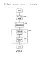
- FIG. 5is a flow chart illustrating an example method that may be used in connection with the system of FIG. 1 for predicting a color from a set of digital values according to another aspect of the present invention.
- the present inventionis believed to be applicable to a variety of color reproduction and display devices.
- the present inventionhas been found to be particularly advantageous for use in color reproduction using halftone printers, dye diffusion devices, and CRTs. While the present invention is not so limited, an appreciation of the invention is best gained through a discussion of these particular application examples.
- a modeling techniquemay be applied to a variety of color reproduction processes.
- Each type of color reproduction processexhibits particular behavioral characteristics that decrease the accuracy of conventional modeling techniques. For example, halftone printers, dye diffusion devices, and CRTs are affected by interactions between the colorant channels.
- the present inventionis directed to calorimetric characterization of a variety of display devices using models that consider interactions between colorant channels more fully than conventional techniques. As a result, the accuracy of the characterization is improved.
- One specific embodiment of the present inventionincorporates a lookup table that compensates for these behavioral characteristics and provides more accurate calorimetric characterizations of display devices.
- This techniquemay be viewed as including two stages.
- a modeling systemcharacterizes a display device by generating a mapping of color coordinates in a device-dependent color space to color coordinates in a device-independent color space.
- the modeling systemuses the device characterization generated in the first stage to predict the device-independent color or spectrum represented by a set of digital values.
- the device characterizationcan be used to build a mapping of digital CMYK values to values in a device-independent color space, such as the CIE L * a * b * coordinate system.
- the L * dimensioncorresponds to lightness
- the a * dimensioncorresponds to redness-greenness
- the b * dimensioncorresponds to yellowness-blueness.
- FIG. 1illustrates an example system according to the present invention configured to model a display device 10 .
- a computer arrangement 12is connected to the display device 10 .
- the computer arrangement 12may be implemented, for example, using a conventional personal computer (such as an Apple- or IBM-compatible computer) and CD-ROM based software or using another computer-based design.
- the computer arrangement 12uses, for example, spectral measurements obtained from the display device 10 .
- the computer arrangement 12can develop the calorimetric model 14 using other device-independent data, such as XYZ tristimulus values.
- the calorimetric model 14maps color values specific to the display device 10 to device-independent color values. For example, assuming the display device 10 is implemented as a halftone printer or a dye diffusion device employing a CMYK colorant scheme, the calorimetric model 14 maps CMYK values presented at an input 24 to a device-independent color space, such as the L * a * b * color space.
- the calorimetric model 14then provides the device-independent color values thus generated at an output 26 .
- the spectral measurementsare optionally provided at an output 27 .
- the model 14incorporates one or more lookup tables (LUTs) 16 in addition to an analytic model 18 .
- the analytic model 18is implemented mathematically, e.g., using the computer arrangement 12 or, as an alternate embodiment, the analytic model is implemented in multiple parts, e.g., using less precise (or less computationally-intense) mathematical equations followed by a value-correcting LUT or LUTs.
- the LUT 16may be implemented using a volatile or nonvolatile memory, such as a data file on a hard disk.
- the computer arrangement 12may store the raw data, e.g., spectral measurements, used in generating the model 14 .
- the model 14optionally also includes a linearization 20 for generating indices for indexing the LUT 16 and a set of reference illuminant and observer curves 22 for converting spectral coordinates to tristimulus values, such as XYZ values, or to another device-independent color space, such as the L * a * b * color space.
- FIG. 2is a flow chart illustrating an example process in which the computer arrangement 12 of FIG. 1 is used in a color reproduction process according to this embodiment of the present invention.
- the computer arrangement 12 of FIG. 1causes the display device 10 , implemented in this example as a halftone printer, to produce a test target. More specifically, the computer arrangement 12 provides test image data to the display device 10 . In response to the test image data, the display device 10 produces a test target, which includes a number of color patches representing the combinations of a small number of color values of each colorant. For a cyan-magenta-yellow-black (CMYK) printer, four values of each colorant (cyan, magenta, yellow, and black) is adequate.
- CYKcyan-magenta-yellow-black
- the patchesare selected so that the values for each colorant represent approximately equal steps in dot areas.
- This selection methodreduces the number of patches and spectral measurements used in creating an accurate model of the halftone printer.
- an alternative selection methodis used. For example, smaller steps in dot areas may be used to increase the accuracy of the model in a particular region of the color space. Decreasing the step size in this manner increases the number of patches and spectral measurements used to characterize the printer. Conversely, a larger step size may be used in certain areas of the color space.
- This alternative selection methoddecreases the number of patches and spectral measurements used to characterize the printer at the expense of accuracy of the model in a region of the color space. Relatively large step sizes are appropriate in certain areas of the color space in which the calorimetric response varies relatively slowly with changes in digital input values.
- a color-measuring instrumentsuch as a Gretag SPM-100 spectrophotometer, generates a database of spectral measurements of the test patches. This process is depicted gat a block 102 .
- the spectral measurements databasedescribes the reflectance of the test patches as a function of wavelength within the visible light spectrum.
- the computer arrangement 12then processes the spectral measurements to characterize the colorimetric response of the halftone printer, thus generating the colorimetric model 14 of FIG. 1 .
- the analytic model 18 of FIG. 1is implemented as a model, such as the model proposed by Viggiano, that characterizes the spectral reflectance of a sample as a function of wavelength. See J. A. Viggiano, “Modeling the Color of Multi-Colored Halftones,” Proc. TAGA 1990, pp. 44-62 (1990).
- This analytic modeluses a spectral form of the Neugebauer equations with a compensating parameter known as the narrowband Yule-Nielsen adjustment parameter or n factor.
- the n factoraccounts for the effect of penetration of light into the paper and is affected by several factors, such as the type of paper used.
- the spectral reflectance of a sampleis computed as a function of wavelength using the equation:
- R′ sample 9 ⁇ )a c R′ c ( ⁇ )+ a m R′ m ( ⁇ )+ a y R′ y ( ⁇ )+
- R x ( ⁇ )denotes the spectral reflectance as a function of wavelength ⁇
- nis the Yule-Nielsen n-factor
- u1/n
- R′ x ( ⁇ )[R x ( ⁇ )] u
- a xare the relative areas of each Neugebauer primary formed by a particular combination of colorants.
- the subscript xdenotes a combination of colorants.
- a cmdenotes the relative area of the Neugebauer primary formed by overprinting cyan and magenta.
- the areas a xare computed using, for example, the DeMichel equations:
- a paper(1 ⁇ c )*(1 ⁇ m )*(1 ⁇ y )*(1 ⁇ k )
- a cc *(1 ⁇ m )*(1 ⁇ y )*(1 ⁇ k )
- c, m, y, and kdenote estimated dot areas for each colorant. It should be understood that these estimated dot areas are dependent on digital input values. Those skilled in the art will appreciate that the other Neugebauer primary areas a x are computed in a similar fashion.
- the computer arrangement 12estimates the n factor from the spectral measurements obtained at the block 102 . This estimation process is depicted at a block 106 .
- the computer arrangement 12estimates the n factor using a conventional technique, such as Powell's method, to minimize the average color error over the database of spectral measurements. See W. H. Press et al., “Numerical Recipes in C, 2nd Ed.,” Cambridge University Press, 1992, p. 412.
- the computer arrangement 12estimates the L * a * b * coordinates for each color in the database using the analytic model 18 .
- the color differences ⁇ E ab between the model-predicted and measured color valuesare averaged over the entire database. Powell's method monitors the successive average color error values to control the search process and determine the best-fit value of n.
- the LUT 16is used to adjust initial dot area estimates to correct for channel interactions in the halftone printer.
- the LUT 16is N-dimensional, where N is the number of colorants. For example, for a CMYK printer, the lookup table has four dimensions.
- the computer arrangement 12uses the analytic model 18 with the n factor to determine, for each test patch, the best-fit or “actual” dot areas (c, m, y, k) that minimize the color difference between the measured and predicted values for each color.
- the computer arrangement 12searches the valid range of dot areas, e.g., 0 to 1.
- the computer arrangement 12may use an unconstrained search method, such as Powell's method, and then constrain the dot areas to the valid range of zero to one using a conventional technique.
- an unconstrained search methodsuch as Powell's method
- For an example technique for constraining unconstrained search techniquesreference may be made to R. W. Hamming, “Numerical Methods for Engineers,” 2d ed., 1973, pp.673-74, incorporated herein by reference.
- another search technique that can be used to find the best-fit dot areasis the Broyden-Fletcher-Goldfarb-Shanno technique. See W. H. Press et al., “Numerical Recipes in C, 2nd Ed.,” Cambridge University Press, 1992, p. 426.
- the computer arrangement 12stores the best-fit dot areas as entries in the LUT 16 .
- the test targetprovides a subset of the total number of entries in the LUT 16 .
- the computer arrangement 12obtains the remaining entries in the LUT 16 using, for example, cubic interpolation. Typically, the interpolated values are also constrained to a range of zero to one. Because dot areas vary slowly across the range or gamut of colors that the halftone printer can produce, the computer arrangement 12 can ensure relatively low color error for intermediate values between test patches by measuring test patches that are uniformly spaced in dot area across the gamut. By measuring these test patches, the computer arrangement anchors the predictive error at zero at uniformly spaced points in the LUT 16 .
- the computer arrangement 12optionally estimates the linearization 20 , implemented in this example using one dimensional transfer functions, from the spectral measurements.
- the linearization c[d c ]may be estimated, for example, by determining a functional fit to channel-independent dot area estimates computed using similar techniques as are used for computing the entries to the LUT 16 .
- the linearizations m[d m ], y[d y ], and k[d k ]may be similarly determined.
- the n factorprovides some compensation for the change in size of dots in a halftone image, known as dot gain, as the image is processed through the various steps in a typical halftone printing process. With the n factor providing some compensation for channel nonlinearity, the linearization 20 is typically only used in extreme cases of channel nonlinearity.
- the computer arrangement 12 of FIG. 1is used in connection with an example process illustrated in FIG. 3 to characterize a dye diffusion device.
- the computer arrangement( 12 of FIG. 1) causes the display device 10 , implemented in this example as a dye diffusion device, to produce a pair of test targets by providing test image data to the dye diffusion device.
- the dye diffusion deviceIn response to the test image data, the dye diffusion device produces two test targets.
- the first test targetincludes step wedges for each colorant with monotonically increasing color values.
- the computer arrangement 12uses the first test target to determine the linearization 20 used in generating indices for indexing the LUT 16 . In certain applications in which the dye diffusion device exhibits a reasonably linear relationship between digital value and dye concentration, the linearization 20 is not required. In such applications, the dye diffusion device need not produce the first test target.
- the second test targetincludes a number of color patches representing the combinations of a small number of color values of each colorant.
- a typical CMYK dye diffusion devicefour values of each colorant (cyan, magenta, yellow, and black) are sufficient.
- the values for each coloranttypically represent approximately equal steps in digital value or dye concentration. Using these values reduces the number of test patches used in creating an accurate model of the dye diffusion device.
- the colors printed on the second test targetmay be determined based on measurements of the first test target. Alternatively, a variety of second test targets having differently-colored patches may be printed, and measurements may be obtained from one of the second test targets.
- test patchesmay be selected to represent smaller steps in dye concentrations in that region. Decreasing the step size in this manner increases the number of patches, but improves the accuracy of the characterization process.
- the test patchesmay be selected to represent larger steps in dye concentrations in those regions.
- a color-measuring instrumentsuch as a spectrophotometer, obtains spectral measurements of the test targets.
- the computer arrangement 12uses these spectral measurements in subsequent steps to generate the calorimetric model 14 of FIG. 1, as depicted generally at a block 204 .
- the analytic model 18 of the calorimetric model 14is implemented using a dye mixing model, which characterizes the spectral reflectance of a sample as a function of wavelength.
- a dye mixing modelwhich characterizes the spectral reflectance of a sample as a function of wavelength.
- One such model, for mixing three dyes,is described in greater detail in R. S. Berns, “Spectral modeling of a dye diffusion thermal transfer printer,” Journal of Electronic Imaging, vol. 2, no. 4, October 1993, pp. 359-70, incorporated herein by reference.
- a version of this model modified for mixing four dyespredicts a reflectance spectrum R ⁇ ,predicated from a set of dye concentration estimates c c , c m , c y , and c k , given measurements of the reflective spectra of the media and the colorants.
- R ⁇denotes reflectance as a function of wavelength ⁇
- k 1 and k 2are constants
- R ⁇ ,mixis the reflectance of the media alone
- K ⁇ ,mixis the spectral absorption of the sample under consideration.
- the sample absorption spectrumis computed as the sum of the absorption of each dye:
- K ⁇ ,mixK ⁇ ,cyan+K ⁇ ,magenta+K ⁇ ,yellow+K ⁇ ,black
- the scalars c c , c m , c y , and c kcan be considered to be normalized dye concentrations in a range between zero and one. For digitally-addressed devices, these concentrations are determined as a function of the CMYK digital values d c , d m , d y , and d k .
- the computer arrangement 12uses the first test target to derive the linearization 20 at a block 206 .
- c m [d m ], c y [d y ], and c k [d k ]are determined in a similar manner. As addressed above, in certain applications in which the dye diffusion device exhibits a reasonably linear relationship between digital values and dye concentration, the linearization 20 is not necessary.
- the computer arrangement 12generates the LUT 16 of FIG. 1 .
- the LUT 16is used in adjusting initial dye concentration estimates to yield corrected dye concentrations for use in the mixing model.
- the second test targetprovides a coarse sampling of the total number of entries in the LUT 16 .
- the computer arrangement 12obtains the remaining entries in the LUT 16 using, for example, a cubic interpolation technique with interpolated values constrained to the range between zero and one. Assuming that dye concentrations vary slowly over the gamut of the dye diffusion device, the computer arrangement 12 can ensure relatively low color error for intermediate values between test patches by measuring test patches that are uniformly spaced across the gamut. By measuring such test patches, the computer arrangement 12 anchors the predictive error at zero at uniformly spaced points in the LUT 16 .
- the computer arrangement 12computes the entries in the LUT 16 using a colorant formulation process. With the previously-measured spectral absorption of the primaries, the computer arrangement 12 determines, using the analytic model 18 , the best-fit or “actual” dye concentrations that minimize the color difference between measured and predicted calorimetric values.
- the colorant formulation processis implemented using a constrained minimization technique to search dye concentration space for the best-fit values in the range between zero and one.
- the best-fit valuesare stored as entries in the LUT 16 .
- the computer arrangement 12 of FIG. 1is used in connection with an example process illustrated in FIG. 4 to characterize a CRT device.
- the computer arrangement 12 of FIG. 1causes the display device 10 , implemented in this embodiment as a CRT, to display two test patterns. More particularly, the computer arrangement 12 provides test image data to the CRT. The CRT subsequently displays two test patterns, each of which includes a number of color patches.
- the computer arrangement 12uses the first test pattern to generate the linearization 20 of FIG. 1 and the analytic model 18 of FIG. 1 .
- the analytic model 18is implemented as a conversion matrix that converts color coordinates in an RGB color space to color coordinates in an XYZ color space.
- R, G, and Bare device dependent tristimulus values computed from RGB digital values d r , d g , and d b using the linearization 20 .
- R max , G max , and B max the RGB tristimulus values corresponding to the monitor white, i.e., the maximum values of red, green, and blue in combination.
- the computer arrangement 12In order to develop the analytic model 18 and linearization 20 of FIG. 1, the computer arrangement 12 first obtains XYZ values of the color patches in the first test pattern using, for example, an X-Rite DPT-92 monitor calorimeter. This process is depicted at a block 302 .
- the first set of color patchesconsists of a neutral step wedge with RGB digital values that increase monotonically and in equal steps.
- the computer arrangement 12generates the conversion matrix, as depicted at a block 304 .
- the computer arrangement 12uses the XYZ values of the maximum red, green, and blue patches to form the matrix in the analytic model 18 .
- the first column of the conversion matrixconsists of the XYZ values of the patch having an R digital value equal to one and G and B digital values equal to zero.
- the second and third columns of the conversion matrixare similarly generated.
- the computer arrangement 12uses the conversion matrix and the first test pattern to calculate the linearization 20 .
- the computer arrangement 12computes the inverse of the conversion matrix to obtain an inverse conversion matrix that converts color coordinates in an XYZ color space to color coordinates in an RGB color space.
- the computer arrangement 12computes RGB tristimulus values using the inverse conversion matrix.
- the computer arrangement 12then divides each of the R, G, and B values thus computed by the maximum R, G, or B values. In this manner, the computer arrangement 12 obtains normalized RGB tristimulus values for each patch of the step wedge.
- the computer arrangement 12then performs a functional fit to the normalized RGB tristimulus values to obtain gain, offset, and gamma parameters for use in the gain-offset-gamma equations above.
- the computer arrangement 12uses the second test pattern in determining the entries of the LUT 16 of FIG. 1 .
- the second test patternincludes a set of color patches representing the combinations of a small number of values of each channel.
- the second test patternmay include five values of each of the three colorants, for a total of 125 color patches.
- the values for each coloranttypically represent approximately equal steps in digital value.
- the computer arrangement 12uses a colorant formulation process to compute the entries to the LUT from XYZ measurements of the color patches. Given the linearization 20 and the analytical model 18 of FIG. 1, the computer arrangement 12 uses these components without the LUT 16 to determine, for each color patch, the best fit or “actual” RGB tristimulus values that minimize the color difference between the measured and predicted values.
- the computer arrangement 12implements the colorant formulation process using a constrained minimization technique to search RGB tristimulus space for the best fit values. The best fit values are used as the entries in the LUT 16 .
- the second set of color patchesprovides a coarse sampling of the total number of entries in the LUT 16 .
- the remaining entries in the LUT 16are obtained using a cubic interpolation technique. Assuming that RGB tristimulus values vary slowly across the device gamut, the computer arrangement 12 can ensure a low error for values between the coarse samples by reducing or minimizing the predictive error at coarsely spaced points in the LUT 16 .
- the computer arrangement 12After generating the LUT 16 , the computer arrangement 12 optionally stores the LUT 16 in a data file.
- This data filemay be, for example, an image file that also contains image data.
- the image fileoptionally also contains the parameters for the model 14 and the color values used in generating the model 14 . Storing the color values allows subsequent derivation of an improved model.
- the computer arrangement 12may store the color data and subsequently generate the LUT 16 . Storing the color data instead of the LUT 16 potentially reduces the size of the data file, particularly when the LUT 16 contains many entries.
- the computer arrangement 12 of FIG. 1predicts a color from a set of digital values using the model 14 generated, for example, by one of the methods discussed above in connection with FIGS. 1-3.
- the model 14can be used to map a set of digital CMYK values to a standard device-independent color space, such as the L * a * b * color space.
- the color thus predictedmay, for example, be displayed on another display device (not shown).
- the model 14receives a set of digital values that represent a color on the display device 10 at the input 24 .
- the digital valuesare typically digital CMYK values d c , d m , d y , and d k .
- FIG. 5illustrates one example method for use in connection with a computer arrangement for predicting the color of a tint from the set of digital values.
- the computer arrangement 12To map the set of digital values to the standard device-independent color space, the computer arrangement 12 first optionally reparameterizes the set of digital values according to the optional linearization functions 20 to obtain a set of initial values, as depicted at a block 400 .
- the display device 10is a halftone printer
- these initial valuesare initial dot area estimates.
- the display device 10is a dye diffusion device
- the initial valuesare initial dye concentration estimates.
- the display device 10is a CRT
- the initial valuesare initial RGB tristimulus estimates.
- the digital valuesthemselves are reasonably linear with respect to the dot areas they produce.
- the computer arrangement 12typically does not use the linearization 20 in such applications. Instead, the computer arrangement 12 uses the digital values as the initial values.
- a block 402at which the computer arrangement 12 addresses the LUT 16 using the initial values.
- the computer arrangement 12thereby retrieves entries from the LUT 16 .
- the LUTcorrects for channel interactions in the display device 10 and other systematic behaviors that are not explicitly considered by the analytic model and, when addressed, provides a set of corrected values. For a halftone printer, these corrected values are corrected dot areas.
- LUTs constructed for dye diffusion modelsprovide corrected dye concentrations.
- LUTs constructed for CRT modelsproduce corrected RGB tristimulus values.
- the lookup processmay use conventional interpolation techniques to compute values between table entries.
- the computer arrangement 12uses the entries retrieved from the LUT 16 in the block 402 in the analytic model 18 appropriate for the class of devices to which the display device 10 belongs. For example, if the display device 10 is a halftone printer, the computer arrangement 12 uses the entries retrieved from the LUT 16 as the estimated dot areas c, m, y, and k in the DeMichel relations. On the other hand, if the display device 10 is a CRT, the corrected RGB tristimulus values retrieved from the LUT 16 are converted to XYZ tristimulus values using the conversion matrix. By using the entries retrieved from the LUT 16 , the computer arrangement 12 obtains a more accurate spectral reflectance or set of XYZ tristimulus values than would be obtained using the initial values.
- the computer arrangement 12After the computer arrangement 12 generates the spectral reflectance or XYZ tristimulus values, flow proceeds to a block 406 .
- the computer arrangement 12optionally applies standard observer and illuminant curves, e.g., a D50 illuminant curve, to convert the spectral reflectance into XYZ tristimulus values, and, optionally, into another standard color space, such as the L * a * b * color space.
- the computer arrangement 12can convert XYZ values directly to L * a * b * color values. In this manner, the computer arrangement 12 predicts a color based on digital values input to the model 14 . This predicted color may then be produced on a second display device, such as a CRT or digital proofing system.
- the computer arrangement 12can develop a highly accurate calorimetric model for a display device using a relatively small number of measurements. Furthermore, the model thus obtained obeys a physical display device model. Accordingly, it exhibits smooth variation, fewer irregularities, and less susceptibility to noise in colorimetric measurements.
Landscapes
- Engineering & Computer Science (AREA)
- Multimedia (AREA)
- Signal Processing (AREA)
- Facsimile Image Signal Circuits (AREA)
- Image Processing (AREA)
Abstract
Description


Claims (38)
Priority Applications (5)
| Application Number | Priority Date | Filing Date | Title |
|---|---|---|---|
| US08/855,709US6232954B1 (en) | 1997-05-08 | 1997-05-08 | Arrangement for high-accuracy colorimetric characterization of display devices and method therefor |
| EP98914403AEP0980628B1 (en) | 1997-05-08 | 1998-04-02 | Arrangement for high-accuracy colorimetric characterization of display devices and method therefor |
| AU68763/98AAU6876398A (en) | 1997-05-08 | 1998-04-02 | Arrangement for high-accuracy colorimetric characterization of display devices and method therefor |
| PCT/US1998/006443WO1998051070A1 (en) | 1997-05-08 | 1998-04-02 | Arrangement for high-accuracy colorimetric characterization of display devices and method therefor |
| DE69806153TDE69806153T2 (en) | 1997-05-08 | 1998-04-02 | ARRANGEMENT AND METHOD FOR HIGHLY ACCURATE COLORIMETRIC CHARACTERIZATION OF DISPLAY DEVICES |
Applications Claiming Priority (1)
| Application Number | Priority Date | Filing Date | Title |
|---|---|---|---|
| US08/855,709US6232954B1 (en) | 1997-05-08 | 1997-05-08 | Arrangement for high-accuracy colorimetric characterization of display devices and method therefor |
Publications (1)
| Publication Number | Publication Date |
|---|---|
| US6232954B1true US6232954B1 (en) | 2001-05-15 |
Family
ID=25321896
Family Applications (1)
| Application Number | Title | Priority Date | Filing Date |
|---|---|---|---|
| US08/855,709Expired - LifetimeUS6232954B1 (en) | 1997-05-08 | 1997-05-08 | Arrangement for high-accuracy colorimetric characterization of display devices and method therefor |
Country Status (5)
| Country | Link |
|---|---|
| US (1) | US6232954B1 (en) |
| EP (1) | EP0980628B1 (en) |
| AU (1) | AU6876398A (en) |
| DE (1) | DE69806153T2 (en) |
| WO (1) | WO1998051070A1 (en) |
Cited By (31)
| Publication number | Priority date | Publication date | Assignee | Title |
|---|---|---|---|---|
| US6373980B2 (en)* | 1997-05-12 | 2002-04-16 | Canon Kabushiki Kaisha | Image processing method and apparatus for transforming the color space of entered image data |
| US20020154326A1 (en)* | 2001-04-06 | 2002-10-24 | Okinori Tsuchiya | Image processing method and apparatus |
| US20030052980A1 (en)* | 2001-08-07 | 2003-03-20 | Brown Wade W. | Calibration of digital color imagery |
| US20030125892A1 (en)* | 2001-12-31 | 2003-07-03 | Edge Christopher J. | Calibration techniques for imaging devices |
| US6647140B1 (en)* | 1999-05-18 | 2003-11-11 | Bank One | Spectrum inverter apparatus and method |
| US6771275B1 (en)* | 2000-06-07 | 2004-08-03 | Oak Technology, Inc. | Processing system and method using a multi-dimensional look-up table |
| US6803933B1 (en)* | 2003-06-16 | 2004-10-12 | Hewlett-Packard Development Company, L.P. | Systems and methods for dot gain determination and dot gain based printing |
| US20050036162A1 (en)* | 2003-04-02 | 2005-02-17 | Edge Christopher J. | Ensuring accurate measurements for soft proofing system |
| US20050099631A1 (en)* | 2002-12-26 | 2005-05-12 | Ming-Feng Yu | Ambient temperature control apparatus used for measuring display panel |
| US7034842B1 (en)* | 1998-10-08 | 2006-04-25 | Mitsubishi Denki Kabushiki Kaisha | Color characteristic description apparatus, color management apparatus, image conversion apparatus and color correction method |
| USRE39161E1 (en) | 1997-07-03 | 2006-07-11 | Eastman Kodak Company | Arrangement for mapping colors between imaging systems and method therefor |
| US20060180767A1 (en)* | 2003-03-11 | 2006-08-17 | David Ramsden | Gamma-ray camera system |
| US20060221093A1 (en)* | 2000-04-11 | 2006-10-05 | Holub Richard A | Methods and apparatus for calibrating a color display |
| US20060232771A1 (en)* | 2005-04-15 | 2006-10-19 | Xerox Corporation | Gray balance calibration of an imaging system |
| US20060262224A1 (en)* | 2005-05-17 | 2006-11-23 | Lg Electronics Inc. | Apparatus and method for compensating for color of video signal in display device |
| US20070091118A1 (en)* | 2005-10-26 | 2007-04-26 | Allen William J | Image display system and method |
| US20070247407A1 (en)* | 2006-04-19 | 2007-10-25 | Quanta Computer Inc. | Gamma adjusting apparatus and method of the same |
| US20080117226A1 (en)* | 1997-06-27 | 2008-05-22 | Edge Christopher J | Method for mapping colors between imaging systems and method therefor |
| WO2008156445A1 (en)* | 2007-06-18 | 2008-12-24 | Thomson Licensing | Method and system for display characterization and content calibration |
| US7710560B2 (en) | 1997-08-25 | 2010-05-04 | Rah Color Technologies, Llc | System for distributing and controlling color reproduction at multiple sites |
| US20100165629A1 (en)* | 2007-07-03 | 2010-07-01 | Sony Corporation | Color-rendering index device |
| US20110109652A1 (en)* | 2007-05-22 | 2011-05-12 | Bongsun Lee | Method and system for prediction of gamma characteristics for a display |
| US20120033937A1 (en)* | 2009-04-15 | 2012-02-09 | Electronics And Telecommunications Research Institute | Method and apparatus for providing metadata for sensory effect, computer-readable recording medium on which metadata for sensory effect are recorded, and method and apparatus for sensory reproduction |
| US20120327433A1 (en)* | 2011-06-21 | 2012-12-27 | Edge Christopher J | Method of designing a color chart |
| US20120327477A1 (en)* | 2011-06-21 | 2012-12-27 | Edge Christopher J | Method of characterizing an imaging system |
| US20130322750A1 (en)* | 2010-10-04 | 2013-12-05 | Datacolor Holding Ag | Method and apparatus for evaluating color in an image |
| US8963947B2 (en) | 2011-01-25 | 2015-02-24 | Dolby Laboratories Licensing Corporation | Enhanced lookup of display driving values |
| US9042682B2 (en) | 2012-05-23 | 2015-05-26 | Dolby Laboratories Licensing Corporation | Content creation using interpolation between content versions |
| US9185266B2 (en) | 2011-06-21 | 2015-11-10 | Eastman Kodak Company | Method of creating an ICC profile for a printing system |
| WO2018194618A1 (en)* | 2017-04-20 | 2018-10-25 | Hewlett-Packard Development Company, L.P. | Combining lookup tables |
| US12385961B2 (en)* | 2023-05-10 | 2025-08-12 | Rohde & Schwarz Gmbh & Co. Kg | Method for total isotropic sensitivity testing of a user equipment |
Families Citing this family (3)
| Publication number | Priority date | Publication date | Assignee | Title |
|---|---|---|---|---|
| DE102009040056B4 (en)* | 2008-09-24 | 2019-10-17 | Heidelberger Druckmaschinen Ag | Method for controlling the application of paint in a printing machine |
| US9478173B2 (en) | 2010-08-30 | 2016-10-25 | Qualcomm Incorporated | Adaptive color correction for display with backlight modulation |
| TWI720862B (en)* | 2020-04-01 | 2021-03-01 | 佳世達科技股份有限公司 | Display device and color adjusting method |
Citations (14)
| Publication number | Priority date | Publication date | Assignee | Title |
|---|---|---|---|---|
| US4393398A (en) | 1980-05-20 | 1983-07-12 | Dai Nippon Printing Co., Ltd. | Apparatus for simulating color printing process |
| US4500919A (en) | 1982-05-04 | 1985-02-19 | Massachusetts Institute Of Technology | Color reproduction system |
| WO1991002427A1 (en) | 1989-08-02 | 1991-02-21 | Eastman Kodak Company | A method and an associated apparatus for calibrating a color digital hardcopy device |
| EP0539868A2 (en) | 1991-10-29 | 1993-05-05 | SHARP Corporation | Color copying machine provided with color correcting circuit |
| US5339176A (en) | 1990-02-05 | 1994-08-16 | Scitex Corporation Ltd. | Apparatus and method for color calibration |
| US5428720A (en)* | 1992-03-27 | 1995-06-27 | Milliken Research Corporation | Method and apparatus for reproducing blended colorants on an electronic display |
| EP0684728A1 (en) | 1994-05-26 | 1995-11-29 | Agfa-Gevaert N.V. | Colour matching by systems calibration, linear and non-linear gamut mapping |
| WO1996008916A1 (en) | 1994-09-13 | 1996-03-21 | Apple Computer, Inc. | Method and system for analytic generation of multidimensional color lookup tables |
| US5526140A (en) | 1995-03-03 | 1996-06-11 | Minnesota Mining And Manufacturing Company | Emulation of a halftone printed image on a continuous-tone device |
| US5543940A (en)* | 1994-02-02 | 1996-08-06 | Electronics For Imaging | Method and apparatus for converting color scanner signals into colorimetric values |
| US5583666A (en)* | 1993-02-12 | 1996-12-10 | Eastman Kodak Company | Method for cross-device color calibration and enhancement using explicit constraints |
| US5754184A (en)* | 1993-01-06 | 1998-05-19 | Eastman Kodak Company | Digital color system and method which provides a visual match across different input and output viewing conditions |
| US5781206A (en)* | 1995-05-01 | 1998-07-14 | Minnesota Mining And Manufacturing Company | Apparatus and method for recalibrating a multi-color imaging system |
| US5963263A (en)* | 1997-06-10 | 1999-10-05 | Winbond Electronic Corp. | Method and apparatus requiring fewer number of look-up tables for converting luminance-chrominance color space signals to RGB color space signals |
- 1997
- 1997-05-08USUS08/855,709patent/US6232954B1/ennot_activeExpired - Lifetime
- 1998
- 1998-04-02WOPCT/US1998/006443patent/WO1998051070A1/enactiveIP Right Grant
- 1998-04-02DEDE69806153Tpatent/DE69806153T2/ennot_activeExpired - Lifetime
- 1998-04-02AUAU68763/98Apatent/AU6876398A/ennot_activeAbandoned
- 1998-04-02EPEP98914403Apatent/EP0980628B1/ennot_activeExpired - Lifetime
Patent Citations (16)
| Publication number | Priority date | Publication date | Assignee | Title |
|---|---|---|---|---|
| US4393398A (en) | 1980-05-20 | 1983-07-12 | Dai Nippon Printing Co., Ltd. | Apparatus for simulating color printing process |
| US4500919A (en) | 1982-05-04 | 1985-02-19 | Massachusetts Institute Of Technology | Color reproduction system |
| WO1991002427A1 (en) | 1989-08-02 | 1991-02-21 | Eastman Kodak Company | A method and an associated apparatus for calibrating a color digital hardcopy device |
| US5053866A (en)* | 1989-08-02 | 1991-10-01 | Eastman Kodak Company | Method and an associated apparatus for calibrating a color digital hardcopy device |
| US5339176A (en) | 1990-02-05 | 1994-08-16 | Scitex Corporation Ltd. | Apparatus and method for color calibration |
| EP0539868A2 (en) | 1991-10-29 | 1993-05-05 | SHARP Corporation | Color copying machine provided with color correcting circuit |
| US5428720A (en)* | 1992-03-27 | 1995-06-27 | Milliken Research Corporation | Method and apparatus for reproducing blended colorants on an electronic display |
| US5754184A (en)* | 1993-01-06 | 1998-05-19 | Eastman Kodak Company | Digital color system and method which provides a visual match across different input and output viewing conditions |
| US5583666A (en)* | 1993-02-12 | 1996-12-10 | Eastman Kodak Company | Method for cross-device color calibration and enhancement using explicit constraints |
| US5543940A (en)* | 1994-02-02 | 1996-08-06 | Electronics For Imaging | Method and apparatus for converting color scanner signals into colorimetric values |
| EP0684728A1 (en) | 1994-05-26 | 1995-11-29 | Agfa-Gevaert N.V. | Colour matching by systems calibration, linear and non-linear gamut mapping |
| WO1996008916A1 (en) | 1994-09-13 | 1996-03-21 | Apple Computer, Inc. | Method and system for analytic generation of multidimensional color lookup tables |
| US5612902A (en)* | 1994-09-13 | 1997-03-18 | Apple Computer, Inc. | Method and system for analytic generation of multi-dimensional color lookup tables |
| US5526140A (en) | 1995-03-03 | 1996-06-11 | Minnesota Mining And Manufacturing Company | Emulation of a halftone printed image on a continuous-tone device |
| US5781206A (en)* | 1995-05-01 | 1998-07-14 | Minnesota Mining And Manufacturing Company | Apparatus and method for recalibrating a multi-color imaging system |
| US5963263A (en)* | 1997-06-10 | 1999-10-05 | Winbond Electronic Corp. | Method and apparatus requiring fewer number of look-up tables for converting luminance-chrominance color space signals to RGB color space signals |
Non-Patent Citations (12)
| Title |
|---|
| E. Allen, "Colorant Formulation and Shading", Optical Radiation Measurements, vol. 2, Color Measurement, F. Grum and C.J. Bartelson, Eds., Academic Press, New York, 1980. |
| F. Sigg, "Errors in Measuring Halftone Dot Areas," Journal of Applied Photographic Engineering, vol. 9, No. 1, Feb. 1983, pp. 27-32. |
| G.T. Hagan, "Resampling Methods for Image Manipulation," The C Users Journal, Aug. 1991, vol. 9, No. 8, pp. 53-58. |
| H.R. Kang, "Color Scanner Calibration," Journal of Imaging Science and Technology, vol. 36, No. 2, Mar./Apr. 1992, pp. 162-170. |
| J.A. Viggiano, "Modeling the Color of Multi-Colored Halftones," Proc. TAGA 1990, pp. 44-62. |
| M. Stokes et al., "Colorimetrically Quantified Visual Tolerances For Pictoral Images," Proceedings 1992, Technical Association of the Graphics Arts and Inter-Society Color Council, Papers presented at the Conference on "Comparison of Color Images Presented in Different Media", Williamsburg, Virginia, Feb. 23-26, 1992, vol. 2, pp. 757-777. |
| R. W. Hamming, Numerical Methods for Scientists and Engineers, 2nd Ed., Dover, New York, 1973, pp. 673-675. |
| R.S. Berns et al., "CRT Colorimetry. Part I: Theory and Practice," Color Research and Application, vol. 18, No. 5, Oct. 1993, pp. 299-314. |
| R.S. Berns et al., "CRT Colorimetry. Part II: Metrology," Color Research and Application, vol. 18, No. 5, Oct. 1993, pp. 315-325. |
| R.S. Berns, "Spectral modeling of a dye diffusion thermal transfer printer", Journal of Electronic Imaging, vol. 2, No. 4, Oct. 1993, pp. 359-370. |
| W.H. Press et al., Numerical Recipes in C, Second Edition, Cambridge University Press, New York, 1992, pp. 412-420. |
| www.altrona Website, "Details: Gain and Offset Control" and "Details: Gamma Correction" DVC Company, Jun. 1995. |
Cited By (68)
| Publication number | Priority date | Publication date | Assignee | Title |
|---|---|---|---|---|
| US6373980B2 (en)* | 1997-05-12 | 2002-04-16 | Canon Kabushiki Kaisha | Image processing method and apparatus for transforming the color space of entered image data |
| US20080117226A1 (en)* | 1997-06-27 | 2008-05-22 | Edge Christopher J | Method for mapping colors between imaging systems and method therefor |
| US20080150960A1 (en)* | 1997-06-27 | 2008-06-26 | Edge Chirstopher J | Method for mapping colors between imaging sytems and method therefor |
| US20080136836A1 (en)* | 1997-06-27 | 2008-06-12 | Edge Christopher J | Method for mapping colors between imaging systems and method therefor |
| US7382379B1 (en) | 1997-06-27 | 2008-06-03 | Eastman Kodak Company | Arrangement for mapping colors between imaging systems and method thereof |
| US20080117227A1 (en)* | 1997-06-27 | 2008-05-22 | Edge Christopher J | Method for mapping colors between imaging systems and method therefor |
| USRE39161E1 (en) | 1997-07-03 | 2006-07-11 | Eastman Kodak Company | Arrangement for mapping colors between imaging systems and method therefor |
| US8917394B2 (en) | 1997-08-25 | 2014-12-23 | Rah Color Technologies Llc | System for distributing and controlling color reproduction at multiple sites |
| US7710560B2 (en) | 1997-08-25 | 2010-05-04 | Rah Color Technologies, Llc | System for distributing and controlling color reproduction at multiple sites |
| US20100231728A1 (en)* | 1997-08-25 | 2010-09-16 | Holub Richard A | System for distributing and controlling color reproduction at multiple sites |
| US9057645B2 (en) | 1997-08-25 | 2015-06-16 | Rah Color Technologies Llc | System for distributing and controlling color reproduction at multiple sites |
| US9404802B2 (en) | 1997-08-25 | 2016-08-02 | Rah Color Technologies Llc | System for distributing and controlling color reproduction at multiple sites |
| US9894338B2 (en) | 1997-08-25 | 2018-02-13 | Rah Color Technologies Llc | System for distributing and controlling color reproduction at multiple sites |
| US8537357B2 (en) | 1997-08-25 | 2013-09-17 | Rah Color Technologies Llc | System for distributing and controlling color reproduction at multiple sites |
| US7034842B1 (en)* | 1998-10-08 | 2006-04-25 | Mitsubishi Denki Kabushiki Kaisha | Color characteristic description apparatus, color management apparatus, image conversion apparatus and color correction method |
| US6647140B1 (en)* | 1999-05-18 | 2003-11-11 | Bank One | Spectrum inverter apparatus and method |
| US7710433B2 (en) | 2000-04-11 | 2010-05-04 | Rah Color Technologies Llc | Methods and apparatus for calibrating a color display |
| US20060221093A1 (en)* | 2000-04-11 | 2006-10-05 | Holub Richard A | Methods and apparatus for calibrating a color display |
| US10008180B2 (en) | 2000-04-11 | 2018-06-26 | Rah Color Technologies Llc | Methods and apparatus for calibrating a color display |
| US8279236B2 (en) | 2000-04-11 | 2012-10-02 | Rah Color Technologies Llc | Methods and apparatus for calibrating a color display |
| US9767763B2 (en) | 2000-04-11 | 2017-09-19 | Rah Color Technologies Llc | Methods and apparatus for calibrating a color display |
| US8665289B2 (en) | 2000-04-11 | 2014-03-04 | RAH Color Technology LLC | Methods and apparatus for calibrating a color display |
| US8009175B2 (en) | 2000-04-11 | 2011-08-30 | Rah Color Technologies Llc | Methods and apparatus for calibrating a color display |
| US9500527B2 (en) | 2000-04-11 | 2016-11-22 | Rah Color Technologies Llc | Methods and apparatus for calibrating a color display |
| US6771275B1 (en)* | 2000-06-07 | 2004-08-03 | Oak Technology, Inc. | Processing system and method using a multi-dimensional look-up table |
| US7312891B2 (en)* | 2001-04-06 | 2007-12-25 | Canon Kabushiki Kaisha | Image processing method and apparatus |
| US20020154326A1 (en)* | 2001-04-06 | 2002-10-24 | Okinori Tsuchiya | Image processing method and apparatus |
| US7362357B2 (en) | 2001-08-07 | 2008-04-22 | Signature Research, Inc. | Calibration of digital color imagery |
| US20030052980A1 (en)* | 2001-08-07 | 2003-03-20 | Brown Wade W. | Calibration of digital color imagery |
| US7509222B2 (en)* | 2001-12-31 | 2009-03-24 | Eastman Kodak Company | Calibration techniques for imaging devices |
| US20030125892A1 (en)* | 2001-12-31 | 2003-07-03 | Edge Christopher J. | Calibration techniques for imaging devices |
| WO2003058980A1 (en)* | 2001-12-31 | 2003-07-17 | Kodak Polychrome Graphics, Llc | Calibration techniques for imaging devices |
| JP2009171594A (en)* | 2001-12-31 | 2009-07-30 | Eastman Kodak Co | Calibration method for imaging apparatus, and computer readable medium |
| US6775633B2 (en) | 2001-12-31 | 2004-08-10 | Kodak Polychrome Graphics, Llc | Calibration techniques for imaging devices |
| US20040218233A1 (en)* | 2001-12-31 | 2004-11-04 | Edge Christopher J. | Calibration techniques for imaging devices |
| US20050099631A1 (en)* | 2002-12-26 | 2005-05-12 | Ming-Feng Yu | Ambient temperature control apparatus used for measuring display panel |
| US7234863B2 (en)* | 2002-12-26 | 2007-06-26 | Chunghwa Picture Tubes, Ltd. | Apparatus for measurement optical characteristic of a display panel |
| US20060180767A1 (en)* | 2003-03-11 | 2006-08-17 | David Ramsden | Gamma-ray camera system |
| US7504635B2 (en)* | 2003-03-11 | 2009-03-17 | Symetrica Limited | Gamma-ray camera system |
| US20050036162A1 (en)* | 2003-04-02 | 2005-02-17 | Edge Christopher J. | Ensuring accurate measurements for soft proofing system |
| US6803933B1 (en)* | 2003-06-16 | 2004-10-12 | Hewlett-Packard Development Company, L.P. | Systems and methods for dot gain determination and dot gain based printing |
| US7733478B2 (en) | 2005-04-15 | 2010-06-08 | Xerox Corporation | Gray balance calibration of an imaging system |
| US7450226B2 (en) | 2005-04-15 | 2008-11-11 | Xerox Corporation | Gray balance calibration of an imaging system |
| US20060232771A1 (en)* | 2005-04-15 | 2006-10-19 | Xerox Corporation | Gray balance calibration of an imaging system |
| US20090059322A1 (en)* | 2005-04-15 | 2009-03-05 | Xerox Corporation | Gray Balance Calibration of an Imaging System |
| US20060262224A1 (en)* | 2005-05-17 | 2006-11-23 | Lg Electronics Inc. | Apparatus and method for compensating for color of video signal in display device |
| US20070091118A1 (en)* | 2005-10-26 | 2007-04-26 | Allen William J | Image display system and method |
| US7453454B2 (en) | 2005-10-26 | 2008-11-18 | Hewlett-Packard Development Company, L.P. | Image display system and method |
| US7884838B2 (en)* | 2006-04-19 | 2011-02-08 | Quanta Computer Inc. | Gamma adjusting apparatus and method of the same |
| US20070247407A1 (en)* | 2006-04-19 | 2007-10-25 | Quanta Computer Inc. | Gamma adjusting apparatus and method of the same |
| US9177499B2 (en) | 2007-05-22 | 2015-11-03 | Thomson Licensing | Method and system for prediction of gamma characteristics for a display |
| US20110109652A1 (en)* | 2007-05-22 | 2011-05-12 | Bongsun Lee | Method and system for prediction of gamma characteristics for a display |
| US20100201667A1 (en)* | 2007-06-18 | 2010-08-12 | Bongsun Lee | Method and system for display characterization and content calibration |
| WO2008156445A1 (en)* | 2007-06-18 | 2008-12-24 | Thomson Licensing | Method and system for display characterization and content calibration |
| US20100165629A1 (en)* | 2007-07-03 | 2010-07-01 | Sony Corporation | Color-rendering index device |
| US20120033937A1 (en)* | 2009-04-15 | 2012-02-09 | Electronics And Telecommunications Research Institute | Method and apparatus for providing metadata for sensory effect, computer-readable recording medium on which metadata for sensory effect are recorded, and method and apparatus for sensory reproduction |
| US9076068B2 (en)* | 2010-10-04 | 2015-07-07 | Datacolor Holding Ag | Method and apparatus for evaluating color in an image |
| US20130322750A1 (en)* | 2010-10-04 | 2013-12-05 | Datacolor Holding Ag | Method and apparatus for evaluating color in an image |
| US8963947B2 (en) | 2011-01-25 | 2015-02-24 | Dolby Laboratories Licensing Corporation | Enhanced lookup of display driving values |
| US9185266B2 (en) | 2011-06-21 | 2015-11-10 | Eastman Kodak Company | Method of creating an ICC profile for a printing system |
| US8824005B2 (en)* | 2011-06-21 | 2014-09-02 | Eastman Kodak Company | Method of designing a color chart |
| US20120327433A1 (en)* | 2011-06-21 | 2012-12-27 | Edge Christopher J | Method of designing a color chart |
| US8570599B2 (en)* | 2011-06-21 | 2013-10-29 | Eastman Kodak Company | Method of characterizing an imaging system |
| US20120327477A1 (en)* | 2011-06-21 | 2012-12-27 | Edge Christopher J | Method of characterizing an imaging system |
| US9042682B2 (en) | 2012-05-23 | 2015-05-26 | Dolby Laboratories Licensing Corporation | Content creation using interpolation between content versions |
| WO2018194618A1 (en)* | 2017-04-20 | 2018-10-25 | Hewlett-Packard Development Company, L.P. | Combining lookup tables |
| US10832106B2 (en) | 2017-04-20 | 2020-11-10 | Hewlett-Packard Development Company, L.P. | Combining lookup tables |
| US12385961B2 (en)* | 2023-05-10 | 2025-08-12 | Rohde & Schwarz Gmbh & Co. Kg | Method for total isotropic sensitivity testing of a user equipment |
Also Published As
| Publication number | Publication date |
|---|---|
| WO1998051070A1 (en) | 1998-11-12 |
| DE69806153T2 (en) | 2003-02-20 |
| AU6876398A (en) | 1998-11-27 |
| EP0980628A1 (en) | 2000-02-23 |
| EP0980628B1 (en) | 2002-06-19 |
| DE69806153D1 (en) | 2002-07-25 |
Similar Documents
| Publication | Publication Date | Title |
|---|---|---|
| US6232954B1 (en) | Arrangement for high-accuracy colorimetric characterization of display devices and method therefor | |
| US7965417B2 (en) | Tone correction table generation method and apparatus | |
| US6225974B1 (en) | Gamut correction with color separation and methods and apparatuses for performing same | |
| US7583420B2 (en) | Image processing method and apparatus | |
| US5481655A (en) | System for matching a picture on a monitor to a printed picture | |
| US5572632A (en) | Universal frame buffer for a rendering device | |
| US5363318A (en) | Method and apparatus for adaptive color characterization and calibration | |
| US5818960A (en) | Characterization calibration | |
| US5787193A (en) | System for converting color image signals from RGB to CMY color spaces through look-up tables | |
| US5881209A (en) | Method and system for automatically generating printer profiles | |
| US20050185200A1 (en) | Systems, methods, and computer program products for converting between color gamuts associated with different image processing devices | |
| JPH08307723A (en) | Method for re-calibrating multicolor image forming system | |
| US7889403B2 (en) | Methods and apparatus for calibrating a digital color imaging device that uses multi-hue colorants | |
| US6331899B1 (en) | Method and apparatus for automatically generating single-channel critical color transformations | |
| US8537417B2 (en) | Method for improved printer characterization | |
| US6134029A (en) | Scanner calibration technique | |
| US7724392B2 (en) | Methods and apparatus for calibrating digital imaging devices | |
| US7630106B2 (en) | Methods and apparatus for determining colorant limits for calibrating digital imaging devices | |
| US7742204B2 (en) | Methods and apparatus for determining a total colorant limit for digital imaging devices | |
| Emmel et al. | Colour calibration for colour reproduction | |
| US6559982B1 (en) | Accurate monitor to printer color reproduction technique | |
| US7391545B2 (en) | Color matching method | |
| Fleming et al. | The Leverage of Gray Balance in Controlling Perceptual and Quantitative Colorimetry | |
| Slavuj et al. | Paper F | |
| EP1784002A1 (en) | Method and apparatus for printer calibration |
Legal Events
| Date | Code | Title | Description |
|---|---|---|---|
| AS | Assignment | Owner name:IMATION CORPORATION, MINNESOTA Free format text:ASSIGNMENT OF ASSIGNORS INTEREST;ASSIGNOR:ROZZI, WILLIAM A.;REEL/FRAME:008547/0431 Effective date:19970506 | |
| AS | Assignment | Owner name:MINNESOTA MINING AND MANUFACTURING COMPANY, MINNES Free format text:ASSIGNMENT OF ASSIGNORS INTEREST;ASSIGNOR:IMATION CORP.;REEL/FRAME:008782/0064 Effective date:19971017 | |
| AS | Assignment | Owner name:IMATION CORP., MINNESOTA Free format text:ASSIGNMENT OF ASSIGNORS INTEREST;ASSIGNOR:3M INNOVATIVE PROPERTIES COMPANY;REEL/FRAME:011570/0919 Effective date:20010116 Owner name:3M INNOVATIVE PROPERTIES COMPANY, MINNESOTA Free format text:ASSIGNMENT OF ASSIGNORS INTEREST;ASSIGNOR:MINNESOTA MINING AND MANUFACTURING COMPANY, A CORPORATION OF DELAWARE;REEL/FRAME:011573/0575 Effective date:20010116 | |
| STCF | Information on status: patent grant | Free format text:PATENTED CASE | |
| FPAY | Fee payment | Year of fee payment:4 | |
| FEPP | Fee payment procedure | Free format text:PAYOR NUMBER ASSIGNED (ORIGINAL EVENT CODE: ASPN); ENTITY STATUS OF PATENT OWNER: LARGE ENTITY | |
| AS | Assignment | Owner name:KODAK POLYCHROME GRAPHICS LLC, CONNECTICUT Free format text:ASSIGNMENT OF ASSIGNORS INTEREST;ASSIGNOR:IMATION CORP.;REEL/FRAME:016460/0327 Effective date:20050425 | |
| AS | Assignment | Owner name:EASTMAN KODAK COMPANY, NEW YORK Free format text:MERGER;ASSIGNOR:KPG HOLDING COMPANY, INC. (FORMERLY KODAK POLYCHROME GRAPHICS LLC);REEL/FRAME:018132/0373 Effective date:20060619 | |
| FPAY | Fee payment | Year of fee payment:8 | |
| AS | Assignment | Owner name:CITICORP NORTH AMERICA, INC., AS AGENT, NEW YORK Free format text:SECURITY INTEREST;ASSIGNORS:EASTMAN KODAK COMPANY;PAKON, INC.;REEL/FRAME:028201/0420 Effective date:20120215 | |
| FPAY | Fee payment | Year of fee payment:12 | |
| AS | Assignment | Owner name:WILMINGTON TRUST, NATIONAL ASSOCIATION, AS AGENT, Free format text:PATENT SECURITY AGREEMENT;ASSIGNORS:EASTMAN KODAK COMPANY;PAKON, INC.;REEL/FRAME:030122/0235 Effective date:20130322 Owner name:WILMINGTON TRUST, NATIONAL ASSOCIATION, AS AGENT, MINNESOTA Free format text:PATENT SECURITY AGREEMENT;ASSIGNORS:EASTMAN KODAK COMPANY;PAKON, INC.;REEL/FRAME:030122/0235 Effective date:20130322 | |
| AS | Assignment | Owner name:JPMORGAN CHASE BANK, N.A., AS ADMINISTRATIVE, DELAWARE Free format text:INTELLECTUAL PROPERTY SECURITY AGREEMENT (FIRST LIEN);ASSIGNORS:EASTMAN KODAK COMPANY;FAR EAST DEVELOPMENT LTD.;FPC INC.;AND OTHERS;REEL/FRAME:031158/0001 Effective date:20130903 Owner name:BARCLAYS BANK PLC, AS ADMINISTRATIVE AGENT, NEW YORK Free format text:INTELLECTUAL PROPERTY SECURITY AGREEMENT (SECOND LIEN);ASSIGNORS:EASTMAN KODAK COMPANY;FAR EAST DEVELOPMENT LTD.;FPC INC.;AND OTHERS;REEL/FRAME:031159/0001 Effective date:20130903 Owner name:BARCLAYS BANK PLC, AS ADMINISTRATIVE AGENT, NEW YO Free format text:INTELLECTUAL PROPERTY SECURITY AGREEMENT (SECOND LIEN);ASSIGNORS:EASTMAN KODAK COMPANY;FAR EAST DEVELOPMENT LTD.;FPC INC.;AND OTHERS;REEL/FRAME:031159/0001 Effective date:20130903 Owner name:EASTMAN KODAK COMPANY, NEW YORK Free format text:RELEASE OF SECURITY INTEREST IN PATENTS;ASSIGNORS:CITICORP NORTH AMERICA, INC., AS SENIOR DIP AGENT;WILMINGTON TRUST, NATIONAL ASSOCIATION, AS JUNIOR DIP AGENT;REEL/FRAME:031157/0451 Effective date:20130903 Owner name:JPMORGAN CHASE BANK, N.A., AS ADMINISTRATIVE, DELA Free format text:INTELLECTUAL PROPERTY SECURITY AGREEMENT (FIRST LIEN);ASSIGNORS:EASTMAN KODAK COMPANY;FAR EAST DEVELOPMENT LTD.;FPC INC.;AND OTHERS;REEL/FRAME:031158/0001 Effective date:20130903 Owner name:PAKON, INC., NEW YORK Free format text:RELEASE OF SECURITY INTEREST IN PATENTS;ASSIGNORS:CITICORP NORTH AMERICA, INC., AS SENIOR DIP AGENT;WILMINGTON TRUST, NATIONAL ASSOCIATION, AS JUNIOR DIP AGENT;REEL/FRAME:031157/0451 Effective date:20130903 Owner name:BANK OF AMERICA N.A., AS AGENT, MASSACHUSETTS Free format text:INTELLECTUAL PROPERTY SECURITY AGREEMENT (ABL);ASSIGNORS:EASTMAN KODAK COMPANY;FAR EAST DEVELOPMENT LTD.;FPC INC.;AND OTHERS;REEL/FRAME:031162/0117 Effective date:20130903 | |
| AS | Assignment | Owner name:EASTMAN KODAK COMPANY, NEW YORK Free format text:RELEASE BY SECURED PARTY;ASSIGNOR:BARCLAYS BANK PLC;REEL/FRAME:041656/0531 Effective date:20170202 | |
| AS | Assignment | Owner name:KODAK PORTUGUESA LIMITED, NEW YORK Free format text:RELEASE BY SECURED PARTY;ASSIGNOR:JP MORGAN CHASE BANK, N.A., AS ADMINISTRATIVE AGENT;REEL/FRAME:049814/0001 Effective date:20190617 Owner name:KODAK (NEAR EAST), INC., NEW YORK Free format text:RELEASE BY SECURED PARTY;ASSIGNOR:JP MORGAN CHASE BANK, N.A., AS ADMINISTRATIVE AGENT;REEL/FRAME:049814/0001 Effective date:20190617 Owner name:PAKON, INC., NEW YORK Free format text:RELEASE BY SECURED PARTY;ASSIGNOR:JP MORGAN CHASE BANK, N.A., AS ADMINISTRATIVE AGENT;REEL/FRAME:049814/0001 Effective date:20190617 Owner name:FAR EAST DEVELOPMENT LTD., NEW YORK Free format text:RELEASE BY SECURED PARTY;ASSIGNOR:JP MORGAN CHASE BANK, N.A., AS ADMINISTRATIVE AGENT;REEL/FRAME:049814/0001 Effective date:20190617 Owner name:CREO MANUFACTURING AMERICA LLC, NEW YORK Free format text:RELEASE BY SECURED PARTY;ASSIGNOR:JP MORGAN CHASE BANK, N.A., AS ADMINISTRATIVE AGENT;REEL/FRAME:049814/0001 Effective date:20190617 Owner name:LASER PACIFIC MEDIA CORPORATION, NEW YORK Free format text:RELEASE BY SECURED PARTY;ASSIGNOR:JP MORGAN CHASE BANK, N.A., AS ADMINISTRATIVE AGENT;REEL/FRAME:049814/0001 Effective date:20190617 Owner name:KODAK AMERICAS, LTD., NEW YORK Free format text:RELEASE BY SECURED PARTY;ASSIGNOR:JP MORGAN CHASE BANK, N.A., AS ADMINISTRATIVE AGENT;REEL/FRAME:049814/0001 Effective date:20190617 Owner name:KODAK AVIATION LEASING LLC, NEW YORK Free format text:RELEASE BY SECURED PARTY;ASSIGNOR:JP MORGAN CHASE BANK, N.A., AS ADMINISTRATIVE AGENT;REEL/FRAME:049814/0001 Effective date:20190617 Owner name:FPC, INC., NEW YORK Free format text:RELEASE BY SECURED PARTY;ASSIGNOR:JP MORGAN CHASE BANK, N.A., AS ADMINISTRATIVE AGENT;REEL/FRAME:049814/0001 Effective date:20190617 Owner name:KODAK PHILIPPINES, LTD., NEW YORK Free format text:RELEASE BY SECURED PARTY;ASSIGNOR:JP MORGAN CHASE BANK, N.A., AS ADMINISTRATIVE AGENT;REEL/FRAME:049814/0001 Effective date:20190617 Owner name:QUALEX, INC., NEW YORK Free format text:RELEASE BY SECURED PARTY;ASSIGNOR:JP MORGAN CHASE BANK, N.A., AS ADMINISTRATIVE AGENT;REEL/FRAME:049814/0001 Effective date:20190617 Owner name:KODAK REALTY, INC., NEW YORK Free format text:RELEASE BY SECURED PARTY;ASSIGNOR:JP MORGAN CHASE BANK, N.A., AS ADMINISTRATIVE AGENT;REEL/FRAME:049814/0001 Effective date:20190617 Owner name:KODAK IMAGING NETWORK, INC., NEW YORK Free format text:RELEASE BY SECURED PARTY;ASSIGNOR:JP MORGAN CHASE BANK, N.A., AS ADMINISTRATIVE AGENT;REEL/FRAME:049814/0001 Effective date:20190617 Owner name:EASTMAN KODAK COMPANY, NEW YORK Free format text:RELEASE BY SECURED PARTY;ASSIGNOR:JP MORGAN CHASE BANK, N.A., AS ADMINISTRATIVE AGENT;REEL/FRAME:049814/0001 Effective date:20190617 Owner name:NPEC, INC., NEW YORK Free format text:RELEASE BY SECURED PARTY;ASSIGNOR:JP MORGAN CHASE BANK, N.A., AS ADMINISTRATIVE AGENT;REEL/FRAME:049814/0001 Effective date:20190617 | |
| AS | Assignment | Owner name:KODAK PHILIPPINES LTD., NEW YORK Free format text:RELEASE BY SECURED PARTY;ASSIGNOR:BARCLAYS BANK PLC;REEL/FRAME:052773/0001 Effective date:20170202 Owner name:KODAK (NEAR EAST) INC., NEW YORK Free format text:RELEASE BY SECURED PARTY;ASSIGNOR:BARCLAYS BANK PLC;REEL/FRAME:052773/0001 Effective date:20170202 Owner name:QUALEX INC., NEW YORK Free format text:RELEASE BY SECURED PARTY;ASSIGNOR:BARCLAYS BANK PLC;REEL/FRAME:052773/0001 Effective date:20170202 Owner name:NPEC INC., NEW YORK Free format text:RELEASE BY SECURED PARTY;ASSIGNOR:BARCLAYS BANK PLC;REEL/FRAME:052773/0001 Effective date:20170202 Owner name:FAR EAST DEVELOPMENT LTD., NEW YORK Free format text:RELEASE BY SECURED PARTY;ASSIGNOR:BARCLAYS BANK PLC;REEL/FRAME:052773/0001 Effective date:20170202 Owner name:LASER PACIFIC MEDIA CORPORATION, NEW YORK Free format text:RELEASE BY SECURED PARTY;ASSIGNOR:BARCLAYS BANK PLC;REEL/FRAME:052773/0001 Effective date:20170202 Owner name:KODAK REALTY INC., NEW YORK Free format text:RELEASE BY SECURED PARTY;ASSIGNOR:BARCLAYS BANK PLC;REEL/FRAME:052773/0001 Effective date:20170202 Owner name:EASTMAN KODAK COMPANY, NEW YORK Free format text:RELEASE BY SECURED PARTY;ASSIGNOR:BARCLAYS BANK PLC;REEL/FRAME:052773/0001 Effective date:20170202 Owner name:KODAK AMERICAS LTD., NEW YORK Free format text:RELEASE BY SECURED PARTY;ASSIGNOR:BARCLAYS BANK PLC;REEL/FRAME:052773/0001 Effective date:20170202 Owner name:FPC INC., NEW YORK Free format text:RELEASE BY SECURED PARTY;ASSIGNOR:BARCLAYS BANK PLC;REEL/FRAME:052773/0001 Effective date:20170202 |