US6232928B1 - Antenna mounting bracket assembly - Google Patents
Antenna mounting bracket assemblyDownload PDFInfo
- Publication number
- US6232928B1 US6232928B1US09/497,425US49742500AUS6232928B1US 6232928 B1US6232928 B1US 6232928B1US 49742500 AUS49742500 AUS 49742500AUS 6232928 B1US6232928 B1US 6232928B1
- Authority
- US
- United States
- Prior art keywords
- antenna
- mounting bracket
- mounting
- bracket
- slots
- Prior art date
- Legal status (The legal status is an assumption and is not a legal conclusion. Google has not performed a legal analysis and makes no representation as to the accuracy of the status listed.)
- Expired - Fee Related
Links
- 230000008878couplingEffects0.000claimsdescription11
- 238000010168coupling processMethods0.000claimsdescription11
- 238000005859coupling reactionMethods0.000claimsdescription11
- 238000000034methodMethods0.000claimsdescription9
- 230000007246mechanismEffects0.000claimsdescription6
- 238000009434installationMethods0.000abstractdescription17
- 230000001413cellular effectEffects0.000description22
- 229910052751metalInorganic materials0.000description4
- 239000002184metalSubstances0.000description4
- 238000004519manufacturing processMethods0.000description3
- 238000004891communicationMethods0.000description2
- 238000010586diagramMethods0.000description2
- 230000006872improvementEffects0.000description2
- 238000003466weldingMethods0.000description2
- 239000000853adhesiveSubstances0.000description1
- 230000001070adhesive effectEffects0.000description1
- 229910052782aluminiumInorganic materials0.000description1
- XAGFODPZIPBFFR-UHFFFAOYSA-NaluminiumChemical compound[Al]XAGFODPZIPBFFR-UHFFFAOYSA-N0.000description1
- 230000000712assemblyEffects0.000description1
- 238000000429assemblyMethods0.000description1
- 230000008901benefitEffects0.000description1
- 238000010276constructionMethods0.000description1
- 238000007796conventional methodMethods0.000description1
- 238000011900installation processMethods0.000description1
- 239000000463materialSubstances0.000description1
- 229920003023plasticPolymers0.000description1
- 239000004033plasticSubstances0.000description1
- 238000007639printingMethods0.000description1
- 230000008569processEffects0.000description1
- 230000000717retained effectEffects0.000description1
- 229910001220stainless steelInorganic materials0.000description1
- 239000010935stainless steelSubstances0.000description1
Images


Classifications
- H—ELECTRICITY
- H01—ELECTRIC ELEMENTS
- H01Q—ANTENNAS, i.e. RADIO AERIALS
- H01Q1/00—Details of, or arrangements associated with, antennas
- H01Q1/12—Supports; Mounting means
- H01Q1/125—Means for positioning
- H—ELECTRICITY
- H01—ELECTRIC ELEMENTS
- H01Q—ANTENNAS, i.e. RADIO AERIALS
- H01Q1/00—Details of, or arrangements associated with, antennas
- H01Q1/12—Supports; Mounting means
- H01Q1/1242—Rigid masts specially adapted for supporting an aerial
Definitions
- the present inventionrelates to an antenna mounting bracket assembly that allows for the mounting of an antenna and for the adjustment of the mechanical tilt position of such an antenna.
- Cellular/PCS (“wireless”) telephone and communications networksrely upon a system of antennas for connecting cellular/PCS devices to the wireless networks.
- the antennas and related cellular/PCS devicessend and receive radio frequency (“RF”) signals between themselves.
- RFradio frequency
- the cellular/PCS antennasare typically mounted on vertical poles that are situated at the top of tall masts, buildings or other structures. These mounting structures, along with the antenna and related hardware, are referred to in the art as “base stations.”
- the antennais better able to send and to receive an RF signal to and from a cellular/PCS device, i.e., the antenna's “view” of the signal from the cellular/PCS device is improved.
- the improved view of the antennaresults from the fact that the antenna is positioned at an elevation above hills, buildings, trees and/or other such objects that may impede and/or obstruct the propagation of the RF signal.
- the use of mechanical downtilt in an antenna mountingcan prevent the RF signal emanating from the antenna from passing over a cellular/PCS device that is located near the antenna and can prevent RF signal interference between the relevant antenna and other cellular/PCS base stations. This enables the antenna's RF signal to be directed downwards toward cellular/PCS device users and away from other cellular/PCS base stations.
- cellular/PCS base stationsutilize antennas that are directed at a downtilt angle of 0° to 10° from the base station's horizontal axis and that are operated with a half-power beamwidth RF signal.
- the mechanical pointing mechanism for the antennamust be capable of providing downtilt adjustment tolerance of one degree (1°) or less and providing an operator with a clear indication of such downtilt adjustment.
- Mounting brackets for use with cellular/PCS antennasare well known in the art. Antenna manufacturers typically include hardware for mounting their antennas to poles and for adjusting the mechanical downtilt of the antenna. Because cellular/PCS antennas are often long and slender and mounted perpendicular to the base station's horizontal axis, prior mounting brackets typically secure the antenna to the pole using two separate, unconnected mounting brackets.
- one of the bracketsis attached to the antenna's upper end and the other bracket is attached to the antenna's lower end.
- the antenna's downtilt positionis induced by pivoting the antenna around the lower mounting bracket.
- the top bracketcan be used for moving the position of the upper end of the antenna about the lower bracket pivot point and as a means for locking the downtilt position of the antenna into the desired position.
- Prior art mounting bracketshave primarily utilized either a “scissors”-type upper bracket or an upper bracket with an adjustable linear slot to adjust the downtilt position of the antenna.
- a linear slot bracketWith respect to linear slot brackets, friction tends to make adjustment throughout the range of motion of the slot difficult and the linear slot assembly may bind as a result. Further, a linear slot assembly does not allow for exact, digital adjustment of an antenna's downtilt position.
- scissors-type bracketssuch brackets normally consist of at least three linkage parts in addition to the upper mounting bracket and, therefore, increase manufacturing and installation time and expense. Also, such brackets typically are adjusted and locked into position through the use of small pins or rods or by tightening the hinge pivot bolt. As a result, assembly and adjustment of these brackets is difficult and time-consuming.
- an antenna mounting assemblythat allows for installation of an antenna by a single installation technician, that reduces that number of parts necessary to complete the installation thereby reducing manufacturing and installation time and expense, that can be modified easily to provide for either analog or digital adjustment of the antenna's downtilt position and that allows for non-binding, readily identifiable adjustment of the antenna's downtilt position.
- the foregoing problems in the prior art for mounting an antenna, such as a cellular/PCS antenna,are solved by the present invention by providing correct spacing and rotational alignment between the upper and lower ends of the antenna.
- the inventionprovides this mounting improvement by utilizing a spine that joins upper and lower mounting brackets into a single, unified mounting bracket assembly.
- the inventionalso solves problems in the prior mounting systems related to adjustment of the antenna's downtilt position.
- the inventionprovides this improvement by utilizing a radial cam bracket system that is easily installed and adjusted either in an analog or digital fashion. The invention can eliminate the need for an additional technician during the assembly process.
- the inventioncan use either a pivot slot and crossbar attachment system for the lower mounting bracket or a radial cam bracket system that utilizes an open-ended “hanger” slot. Both of these attachment systems provide a novel means for retaining the antenna in a substantially upright, vertical position after it is mounted on the mounting bracket. This advantage allows for the completion of the assembly of an antenna base station with the use of only a single technician.
- the present inventionprovides an antenna mounting bracket assembly for attaching an antenna to a support structure, such as a vertical pole.
- This bracket assemblyprovides a spine that maintains a spaced-apart relationship between two mounting brackets attached to the spine.
- the spinealso maintains an identical azimuth rotation position between the two mounting brackets.
- the first mounting bracketis typically positioned above the second mounting bracket and fixed onto the spine.
- the second mounting bracketalso can be fixed in position below the first mounting bracket on the spine.
- the first and second mounting bracketsfunction as receptacles for accepting antenna mounting devices.
- the assemblyalso includes a cam bracket that is adapted to connect the upper end of the antenna and received by the mounting bracket while allowing for the slidable adjustment of the downward tilt position of the antenna relative to the vertical axis of the support structure.
- the lower mounting bracketis adapted to receive the lower end of the antenna and to allow for the pivotal adjustment of the antenna about the lower mounting bracket.
- the upper and lower mounting bracketscontain slots for accepting band clamps which are used to attach the mounting bracket assembly to the support structure.
- the lower mounting bracketincludes a pair of spaced-apart “L”-shaped mounting slots for slidably accepting a horizontal fastener that is attached to the antenna. These mounting slots allow the antenna to pivot about the lower mounting bracket.
- the lower mounting bracketmay also include a crossbar below and between the mounting slots which, in combination with the “L”-shaped slots, prevents the antenna from extending beyond a predetermined downtilt position when an antenna is placed in the mounting slots.
- the cam bracketcan include two spaced-apart radial slots that are in alignment with each other and that allow the upper end of the antenna to pivot relative to the pivot point of the lower mounting bracket.
- the cam bracketalso includes a guiding fastener that serves to connect the upper end of the antenna to the cam bracket.
- the guiding fastenercan slidably move between and within the radial slots so as to allow for the analog adjustment of the downtilt position of the antenna.
- the guiding fastenermay also be capable of locking the cam bracket and, therefore, the antenna into a chosen downtilt position.
- the cam bracket and/or guiding fastenermay be marked with a position indicator so as to allow an installation technician to readily identify the downtilt position of the antenna.
- the cam bracketmay have a second set of radial slots that are located near to the connection point between the cam bracket and the upper mounting bracket.
- the cam bracketincludes a second guiding fastener that slidably moves between and within the secondary radial slots so as to allow for the analog adjustment of the downtilt position of the antenna and to prevent the cam bracket from binding during such adjustment.
- the second guiding fastenermay also be capable of locking the cam bracket and, therefore, the antenna into a chosen downtilt position.
- the cam bracketincludes two spaced-apart radial slots that are in alignment with each other and that allow the upper end of the antenna to pivot relative to the pivot point of the lower mounting bracket.
- the radial slotscomprise a series of detents extending along their edges. The detents allow for the exact, digital adjustment of downtilt position by moving the guiding fastener into a chosen detent.
- the cam bracketincludes a secondary set of spaced-apart radial slots that are in alignment with each other and that are open at one end.
- the secondary radial slotsare adapted to slidably mount upon a guiding fastener that is installed in the upper mounting bracket.
- the upper mounting bracketcontains a set of spaced-apart linear slots that are in alignment with each other and that are open at one end.
- the linear slotsare adapted for slidably receiving a guiding fastener that is installed in the cam bracket.
- the combination of secondary radial slots and linear slotsare utilized to allow the antenna and attached cam bracket to be mounted upon the upper mounting bracket.
- the lower mounting bracketincludes a spaced-apart set of mounting holes for receiving a fastener for connecting the lower end of the antenna to the mounting assembly and for allowing the antenna to be pivoted about the lower mounting bracket.
- FIG. 1is a perspective view of an antenna mounting bracket and accompanying cellular/PCS antenna assembled on a vertical pole according to an exemplary embodiment of the present invention.
- FIG. 2 Ais an exploded perspective view of the antenna mounting bracket and accompanying cellular/PCS antenna of FIG. 1 .
- FIG. 2Bis an enlarged view of the bottom portion of the antenna mounting bracket and accompanying antenna of FIG. 1 .
- FIG. 3is a perspective view of the unassembled antenna mounting bracket of FIG. 1 with the downtilt cam bracket removed from the antenna mounting bracket.
- FIG. 4Ais a top view of the antenna mounting bracket of FIG. 1 mounted on a small diameter vertical pole.
- FIG. 4Bis a top view of the antenna mounting bracket of FIG. 1 mounted on a large diameter vertical pole.
- FIG. 5is a view of the upper portion of the antenna mounting bracket and accompanying cellular/PCS antenna of FIG. 1 .
- FIG. 6is a view of a downtilt cam bracket section of an antenna mounting bracket assembly according to an exemplary embodiment of the present invention.
- FIG. 7is a view of the top portion of an antenna mounting bracket and accompanying cellular/PCS antenna assembled on a vertical pole according to an exemplary embodiment of the present invention.
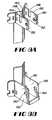
- FIG. 8Ais a view of an upper mounting bracket section of an antenna mounting bracket assembly according to an exemplary embodiment of the present invention.
- FIG. 8Bis a view of a lower mounting bracket section of an antenna mounting bracket assembly according to an exemplary embodiment of the present invention.
- FIG. 9Ais a flow diagram representing a method of attaching an antenna to an antenna mounting bracket assembly and to a support structure according to an exemplary embodiment of the present invention.
- FIG. 9Bis a flow diagram representing a method of attaching an antenna to an antenna mounting bracket assembly and to a support structure according to an exemplary embodiment of the present invention.
- the present inventionis directed to an improved antenna mounting bracket assembly for mounting an antenna to a support.
- the antenna mounting bracket assemblyincludes a spine that joins two mounting brackets to form a single, unified mounting bracket assembly.
- a cam bracketcan be used for adjusting the downtilt position of an accompanying cellular/PCS antenna.
- the spineprovides for correct vertical and rotational spacing between the upper and lower mounting brackets.
- the mounting bracket assemblycan be constructed to allow for either variable, analog adjustment of the antenna downtilt position or to allow for fixed, digital adjustment of the antenna downtilt position.
- the mounting bracket assemblyallows for the installation of the assembly and antenna by a single installation technician.
- FIGS. 1, 2 A and 2 Bprovide perspective and enlarged views of an exemplary antenna mounting bracket assembly 10 constructed in accordance with the present invention.
- the antenna mounting assembly 10includes a spine 12 , an upper mounting bracket 14 , a lower mounting bracket 16 and a cam bracket 18 .
- the spine 12maintains a spaced-apart relationship between the lower mounting bracket 16 and the upper mounting bracket 14 at a length that is typically shorter than the length of an accompanying cellular/PCS antenna 20 .
- the spine 12maintains the identical azimuth rotation relative to the spine's vertical axis between the lower mounting bracket 16 and the upper mounting bracket 14 .
- the complete antenna mounting bracket assembly 10is attached to a support structure, such as a vertical pole 22 , by fasteners, such as band clamps 24 .
- the cam bracket 18can be connected to the upper mounting bracket 14 and the upper end 25 of the antenna 20 .
- the lower mounting bracket 16is preferably connected directly to the lower end 26 of the antenna 20 . It will be appreciated that the upper and lower mounting bracket 14 and 16 operate as receptacles to receive antenna mounting devices.
- the antenna mounting assembly 10utilizes a radial cam bracket 18 , which forms a cam mechanism to produce variation in the antenna's downtilt position by manipulating the position of the upper end 25 of the antenna 20 .
- the assembly 10also utilizes a slotted pivot mechanism in the lower mounting bracket 16 to correspond to the variation of the antenna's downtilt position.
- the antenna 20 in this embodimentis mounted upon the lower mounting bracket 16 by placing a pair of guiding fasteners 29 into a pair of spaced-apart “L”-shaped slots 27 formed into the lower mounting bracket 16 .
- the lower mounting bracket 16also includes a crossbar 28 that is formed below and between the “L”-shaped slots 27 .
- the crossbar 28in combination with the “L”-shaped slots 27 , allows the antenna 20 to be mounted on the lower mounting bracket 16 , but prevents it from extending beyond a predetermined downtilt position when the antenna 20 is unattached to the cam bracket 18 .
- FIG. 3provides a perspective view of the mounting bracket assembly 10 with the cam bracket 18 detached from the assembly 10 .
- the spine 12 , lower mounting bracket 16 and upper mounting bracket 14are constructed as a single, unified assembly by forming and welding sheet metal. This method of construction is well known in the art, is inexpensive and reduces the number of pieces to be assembled during the installation process.
- the spine 12is formed as a “V”-shaped channel 30 , which is particularly adapted for attachment to a cylindrical support structure, such as a vertical pole 22 .
- the spine 12is formed with a set of tabs 32 , 34 at each end that are disposed at an angle parallel to that of the “V”-shaped channel 30 .
- the tabs 32 , 34are adapted for attaching to corresponding tabs 36 , 38 on the lower mounting bracket 16 and upper mounting bracket 14 by means including but not limited to welding, fusing and adhesives.
- a set of spaced-apart, open rectangular slots 40are cut or “punched” into the tabs 32 , 34 .
- Each slot 40is positioned at the distal end 42 of the tabs 32 , 34 and parallel to the spine's vertical axis.
- These slots 40are identical in size and shape to a set of slots 44 punched in the tabs 36 , 38 formed as part of the lower mounting bracket 16 and the upper mounting bracket 14 described below.
- the lower mounting bracket 16is formed with two sidewalls 46 that are disposed parallel to each other and perpendicular to the spine's vertical axis.
- a pair of rectangular slots 48are punched into the sidewalls 46 parallel to the spine's vertical axis, near the sidewalls' proximal ends 50 and towards the sidewall's lower edge 52 .
- These slots 48are adapted for receiving the strap 54 of a band clamp 24 for attaching the antenna mounting assembly 10 to a support structure.
- An open “L”-shaped slot 27is also punched into each sidewall 46 .
- a crossbar 28is formed between the sidewalls 46 and below the lower, closed end 56 of the “L”-shaped slots 27 .
- the lower mounting bracket 16also includes a crossbar 28 that is formed between the sidewalls 46 and below the “L”-shaped slots 27 .
- the antenna 20is mounted upon the lower mounting bracket 16 by slidably placing a guiding fastener (or fasteners) 29 , such as a nut and bolt combination, rods, bolts or pins, into the “L”-shaped slots 27 , which are adapted to receive the guiding fastener (or fasteners) 29 .
- the guiding fastener (or fasteners) 29is attached to a coupling bracket 58 that is formed into the lower end 26 of the antenna 20 .
- the guiding fastener (or fasteners) 29may be allowed to rest against the upper edge 60 of the “L”-shaped slots 27 and the lower edge of the frame 62 of the antenna 20 may be allowed to rest against the crossbar 28 .
- This combinationprevents the antenna 20 from extending beyond a predetermined downtilt position thereby allowing a single installation technician to connect the cam bracket 18 to the upper mounting bracket 14 without the assistance of a second installation technician.
- the lower mounting bracket 16also includes two tabs 38 , which are disposed at an angle parallel to that of the spine's corresponding tabs 34 .
- a set of rectangular slots 64are punched into the tabs 38 parallel to the spine's vertical axis and near a proximal tab 66 .
- the slots 64are adapted to receive the strap of a smaller diameter band clamp 68 for attaching the mounting bracket assembly 10 to a smaller diameter mounting structure 70 .
- a second set of open rectangular slots 44are punched into the distal ends of the tabs 38 parallel to the spine's vertical axis.
- the slots 44are adapted to receive the strap of a larger diameter band clamp 76 for attaching the mounting bracket assembly to a larger diameter mounting structure 78 .
- the mounting bracket assembly 10includes an upper mounting bracket 14 that is formed with two sidewalls 80 that are disposed parallel to each other and preferably parallel to the sidewalls 46 of the lower mounting bracket 16 and perpendicular to the spine's vertical axis.
- Two sets of holes 82 , 84are punched into the sidewalls 80 along the horizontal axis of the sidewalls 80 .
- One set of holes 82is located near the proximal end 86 of the sidewalls 80 .
- Another set of holes 84is located near the distal end 88 of the sidewalls 80 .
- Short, cylindrical mounting sleeves 90are press-fit into each of the sidewall holes 82 , 84 . As can be seen more clearly in FIG.
- each set of mounting sleeves 90are adapted for receiving a guiding fastener (or fasteners) 92 , including but not limited to a bolt and nut combination, rods or pins.
- a pair of rectangular slots 94are punched into the sidewalls 80 parallel to the spine's vertical axis, near the sidewalls' proximal ends 86 .
- the upper mounting bracket 14also includes two tabs 36 , which are disposed at an angle parallel to that of the spine's corresponding tabs 32 .
- a set of rectangular slots 96are punched into the side walls 80 parallel to the spine's vertical axis and near the proximal end 98 of each tab 36 .
- the slots 96are adapted for receiving the strap of a smaller diameter band clamp 68 for attaching the mounting bracket assembly to a smaller diameter mounting structure 70 .
- a second set of rectangular slots 44are punched into the tabs 36 parallel to the spine's vertical axis. Each slot 44 is positioned at the distal end 100 of the tab 36 and is adapted to receive the strap of a larger diameter band clamp 76 for attaching the mounting bracket assembly to a larger diameter mounting structure 78 .
- FIGS. 4A and 4Bprovide top views of the mounting bracket assembly 10 connected to two support structures 70 , 78 , namely a small diameter vertical pole 70 in FIG. 4A and a large diameter vertical pole 78 in FIG. 4 B.
- the strap of a small diameter band clamp 68is passed through the set of slots 94 punched in the sidewalls 80 of the upper mounting bracket 14 and through the set of slots 96 located nearer to the proximal end 98 of the tabs 38 of the upper mounting bracket 14 .
- FIG. 4Athe strap of a small diameter band clamp 68 is passed through the set of slots 94 punched in the sidewalls 80 of the upper mounting bracket 14 and through the set of slots 96 located nearer to the proximal end 98 of the tabs 38 of the upper mounting bracket 14 .
- a strap of a larger diameter band clamp 76is passed through the set of slots 94 punched in the sidewalls 80 of the upper mounting bracket 14 and through the set of slots 101 located at the distal end 102 of the tabs 38 of the upper mounting bracket 14 .
- FIG. 5provides a perspective view of the upper portion of the antenna mounting bracket assembly 10 .
- a cam bracket 18is connected to both the upper mounting bracket 14 and the upper end 25 of the antenna 20 .
- the cam bracket 18is formed with two sidewalls 106 that are parallel to each other and with a rear wall 108 that is perpendicular to the sidewalls 106 .
- a set of holes 110is punched in the proximal end 112 of sidewalls 106 and are adapted for receiving a pivoting fastener 114 to connect the cam bracket 18 to the upper mounting bracket 14 .
- the cam bracket 18pivots about the pivoting fastener's connection point.
- the pivoting fastener 114may provide for locking the antenna's downtilt position through the use of a locking fastener 116 , such as a locking nut or locking washer.
- Two radial slots 118are punched in the sidewalls 106 of the cam bracket 18 and are located near the distal end 120 of the cam bracket 18 and are formed along congruent radii.
- the radial slots 118are adapted to receive a guiding fastener (or fasteners) 120 , such as a bolt and nut combination, rods or pins.
- the guiding fastener (or fasteners) 120is also attached to a coupling bracket 122 that is formed into the upper end 25 of the antenna 20 .
- the combination of the radial slots 118 and the guiding fastener (or fasteners) 120provide a slidable cam mechanism that allows for the analog, slidable adjustment of the antenna's downtilt position.
- the slots 118are formed so as to allow for a maximum downtilt position of ten degrees (10°). However, the slots 118 can be reduced and/or increased in length and radius so as to allow for a greater or smaller range of adjustment.
- the guiding fastener (or fasteners) 120may provide for locking the antenna's downtilt position through the use of a locking fastener 120 , such as a locking nut or locking washer.
- the cam bracket 18is constructed of sheet metal and is marked about the radial slots 118 so as to readily indicate the antenna's downtilt position.
- the slots 118may be marked by conventional methods including metal stamping, engraving or printing.
- the coupling bracket 122 that is formed as part of the antenna 20can be marked with an position indicator 124 that corresponds with the position markings 126 on the radial slots 118 so as to indicate readily the antenna's downtilt position.
- two additional radial slots 128can be punched in the sidewalls 106 of the cam bracket 18 , near the proximal end 112 of the cam bracket 18 , and formed to follow congruent radii.
- These radial slots 128are adapted to slidably receive a guiding fastener (or fasteners) 130 , such as a bolt and nut combination, rods or pins, so as to connect the cam bracket 18 to the upper mounting bracket 14 and to allow the slidable adjustment of the antenna's downtilt position.
- This additional set of radial slots 128provides a more stable adjustment of the antenna's downtilt position and prevents the cam bracket 18 and upper mounting bracket 14 from binding during such adjustment.
- the guiding fastener 130 associated with the additional set of radial slots 128may also provide for locking the antenna's downtilt position through the use of a locking fastener 130 , such as a locking nut or locking washer.
- FIG. 6provides a side view of a cam bracket 132 of another embodiment of the present invention.
- the primary set of radial slots 134are punched into the cam bracket in the form of a series of detents 136 that run along the length of the radii of the slots 134 .
- the detents 136are disposed relative to each other such that the guiding fastener 130 may be moved digitally between each detent position. This enables an adjustment of the antenna's downtilt position by an exact, digital amount, shown in FIG. 6 in one degree (1°) increments up to a maximum of ten degrees (10°).
- FIG. 7provides a side view of a cam bracket 138 and an upper mounting bracket 140 of another embodiment of the present invention.
- a secondary set of open radial slots 142are punched into the proximal end 144 of the cam bracket 138 .
- the radial slots 142are adapted for slidably receiving a guiding fastener (or fasteners) 146 connected to linear slots 148 of the upper mounting bracket 140 .
- the guiding fastener (or fasteners) 146may also provide for locking the antenna's downtilt position through the use of a locking fastener (or fasteners) 146 , such as a locking nut or locking washer.
- a set of open linear slots 148can be punched into the upper edge 150 of the sidewalls 152 of the upper mounting bracket 140 and are parallel to each other and the spine's vertical axis and are located equidistant from the proximal end 154 of the sidewalls 152 .
- the linear slots 148are adapted for slidably receiving a guiding fastener (or fasteners) 146 that is connected to the cam bracket 138 .
- the guiding fastener (or fasteners) 146 associated with the linear slots 148may also provide for locking the antenna's downtilt position through the use of a locking fastener (or fasteners) 146 , such as a locking nut or locking washer.
- the lower mounting bracket 158contains a set of pivot holes 160 disposed within its sidewalls 162 . These holes 160 are adapted for pivotally receiving a fastener (or fasteners).
- the fasteners (or fasteners) associated with the pivot holes 160can also provide for locking the antenna's downtilt position through the use of a locking fastener, such as a locking nut or locking washer.
- the combination of the open linear slots 148 and the open radial slots 142allow an installation technician to mount the assembled cam bracket 138 and antenna 20 upon the upper mounting bracket 140 while maintaining the antenna 20 in a substantially vertical position while the antenna 20 is unattached to the lower mounting bracket 158 . This allows the antenna 20 to be installed by a single technician and overcomes the need for the use of a second installation technician.
- the present inventionalso comprises two methods for attaching an antenna 20 to an antenna mounting bracket assembly 10 and to a support structure, such as a vertical pole 22 .
- a support structuresuch as a vertical pole 22 .
- an upper mounting bracket 14 and a lower mounting bracket 16are attached to a spine 12 so as to maintain the upper mounting bracket 14 and the lower mounting bracket 16 in a spaced-apart relationship along a vertical axis.
- a cam bracket 18is attached to one end of an antenna 20 for slidably adjusting the downtilt position of the antenna 20 relative to the vertical axis of the support structure 17 .
- the spine 12is attached to the support structure 17 .
- Step 174the antenna 20 is mounted upon the lower mounting bracket 16 for pivotal coupling of the antenna 20 .
- Step 176the cam bracket 18 is attached to the upper mounting bracket 14 so as to allow the antenna's downtilt position to be adjusted through manipulation of the cam bracket 18 .
- Step 178an upper mounting bracket 140 and a lower mounting bracket 158 are attached to a spine 12 so as to maintain the upper mounting bracket 140 and the lower mounting bracket 158 in a spaced-apart relationship along a vertical axis.
- a cam bracket 132is attached to one end of an antenna 20 for slidably adjusting the downtilt position of the antenna 20 relative to the vertical axis of the support structure 17 .
- the spine 12is attached to the support structure 17 .
- the antenna 20 and cam bracket 18are mounted upon the upper mounting bracket 140 for pivotal coupling of the antenna 20 .
- the cam bracket 132is attached to the lower mounting bracket 158 so as to allow the antenna's downtilt position to be adjusted through manipulation of the cam bracket 132 .
- the present inventionprovides an antenna mounting bracket assembly that allows for proper vertical and rotational spacing of the brackets for mounting a cellular/PCS antenna.
- the present inventionalso reduces the number of separate pieces necessary for installation of such an antenna and, therefore, reduces the cost and time required to manufacture and install such an assembly. Further, the present invention reduces the number of installation technicians necessary for such installation and assembly from two to one.
- present inventionis applicable to a range of antennas having different heights, widths and profiles, including antennas other than those used for cellular/PCS applications.
- the inventionis also applicable to allow for a wide range of antenna downtilt adjustment and can be configured so as to provide upwards tilt if so desired.
- the present inventioncan be constructed out of a wide range of materials, including but not limited to sheet metal, aluminum, stainless steel and a variety of plastics.
Landscapes
- Support Of Aerials (AREA)
Abstract
Description
Claims (21)
Priority Applications (2)
| Application Number | Priority Date | Filing Date | Title |
|---|---|---|---|
| US09/497,425US6232928B1 (en) | 2000-02-03 | 2000-02-03 | Antenna mounting bracket assembly |
| BR0003156-9ABR0003156A (en) | 2000-02-03 | 2000-07-26 | Antenna mounting bracket set |
Applications Claiming Priority (1)
| Application Number | Priority Date | Filing Date | Title |
|---|---|---|---|
| US09/497,425US6232928B1 (en) | 2000-02-03 | 2000-02-03 | Antenna mounting bracket assembly |
Publications (1)
| Publication Number | Publication Date |
|---|---|
| US6232928B1true US6232928B1 (en) | 2001-05-15 |
Family
ID=23976806
Family Applications (1)
| Application Number | Title | Priority Date | Filing Date |
|---|---|---|---|
| US09/497,425Expired - Fee RelatedUS6232928B1 (en) | 2000-02-03 | 2000-02-03 | Antenna mounting bracket assembly |
Country Status (2)
| Country | Link |
|---|---|
| US (1) | US6232928B1 (en) |
| BR (1) | BR0003156A (en) |
Cited By (54)
| Publication number | Priority date | Publication date | Assignee | Title |
|---|---|---|---|---|
| USD474398S1 (en) | 2002-01-15 | 2003-05-13 | Synchro-Start Products, Inc. | Compound mounting bracket for a solenoid |
| US20040119655A1 (en)* | 2002-12-20 | 2004-06-24 | Hunt Robert E. | Antenna mounting assembly and method |
| US6864847B2 (en) | 2002-02-22 | 2005-03-08 | Jan Blair Wensink | System for remotely adjusting antennas |
| US20050057427A1 (en)* | 2002-02-22 | 2005-03-17 | Wensink Jan B. | System for remotely adjusting antennas |
| US20060092090A1 (en)* | 2004-11-04 | 2006-05-04 | Tennagon, Inc. | Antenna tower mounting assembly and method |
| US20060107984A1 (en)* | 2004-11-19 | 2006-05-25 | Avery Bryan K | Umbrella support device and serving trays |
| US7113145B1 (en) | 2005-05-23 | 2006-09-26 | Valmont Industries, Inc. | Antenna mounting bracket assembly |
| US20070210978A1 (en)* | 2006-03-10 | 2007-09-13 | Winegard Company | Satellite dish antenna mounting system |
| US20070287502A1 (en)* | 2006-06-09 | 2007-12-13 | Smartant Telecom Co., Ltd. | Antenna assembly |
| US20080012785A1 (en)* | 2006-07-13 | 2008-01-17 | Ems Technologies, Inc. | Universal mounting assembly |
| US20080011919A1 (en)* | 2006-07-13 | 2008-01-17 | Accton Technology Corporation | Fixing device |
| WO2008039830A3 (en)* | 2006-09-26 | 2008-07-24 | Extenet Systems Inc | A method and apparatus for using distributed antennas |
| US20080307746A1 (en)* | 2007-06-15 | 2008-12-18 | Lewis Michael S | Pivoting device and method for ceiling panels |
| WO2009008601A1 (en)* | 2007-07-11 | 2009-01-15 | Idoit Co., Ltd. | Support bracket for satellite antenna |
| US20090297476A1 (en)* | 2007-05-10 | 2009-12-03 | Intermune, Inc. | Novel peptide inhibitors of hepatitis c virus replication |
| US20100224750A1 (en)* | 2009-03-04 | 2010-09-09 | Nimrod Webber | Loudspeaker tilting adapter |
| US20100329780A1 (en)* | 2009-06-24 | 2010-12-30 | Echostar Technologies L.L.C. | Bushing and coupling system |
| US20110225804A1 (en)* | 2010-03-19 | 2011-09-22 | Multiwave Sensors Inc. | Apparatus and method for aligning an antenna in a reference position |
| US20120211624A1 (en)* | 2011-02-23 | 2012-08-23 | Hung-Yuan Lin | Adjusting mechanism for adjusting rotary angle and antenna system therewith |
| US20120291368A1 (en)* | 2011-05-17 | 2012-11-22 | Wilbur L. Anderson, Inc. D/B/A Western Towers | Tilt tower assembly and a method of using the same, and a method to ship and assemble a tilt tower |
| US20120325997A1 (en)* | 2011-06-22 | 2012-12-27 | Hon Hai Precision Industry Co., Ltd. | Antenna bracket with adjusting funtion |
| US20130256477A1 (en)* | 2012-03-29 | 2013-10-03 | Andrew Wireless Systems Gmbh | Latching Mounting Assembly |
| US8641002B2 (en) | 2011-05-20 | 2014-02-04 | Art Hand | Tower mounting apparatus |
| EP2341188A3 (en)* | 2010-01-04 | 2014-06-11 | Acquaalta Schutzsysteme GmbH | Adapter device |
| US20140339383A1 (en)* | 2013-05-14 | 2014-11-20 | V.I.T. Products, Inc. | Mast |
| US20150083875A1 (en)* | 2013-06-06 | 2015-03-26 | Global Invacom Ltd | Antenna assembly mounting system |
| US20150136920A1 (en)* | 2012-06-11 | 2015-05-21 | Cue Dee Ab | Arrangement For Mounting A Directional Antenna In An Adjustable Inclined Position |
| CN105101481A (en)* | 2014-04-16 | 2015-11-25 | 华为技术有限公司 | a wireless base station |
| US20150380806A1 (en)* | 2014-06-30 | 2015-12-31 | John Mezzalingua Associates, LLC | Mounting assembly for an integrated remote radio head and antenna system |
| WO2016036951A1 (en)* | 2014-09-04 | 2016-03-10 | Commscope Technologies Llc | Azimuth and elevation angle pole mounting system for wireless communications base sites |
| US9553350B2 (en) | 2015-05-14 | 2017-01-24 | Micro Wireless Solutions, Corp. | Antenna mount assembly |
| CN107425253A (en)* | 2016-05-23 | 2017-12-01 | 安弗施无线射频系统(上海)有限公司 | A kind of mounting bracket and mounting interface |
| US20170352939A1 (en)* | 2015-02-26 | 2017-12-07 | Huawei Technologies Co., Ltd. | Radio frequency assembly |
| US20190063670A1 (en)* | 2017-08-31 | 2019-02-28 | Groundprobe Pty Ltd | Lidar hinged mount |
| CN109473783A (en)* | 2018-10-31 | 2019-03-15 | 中天宽带技术有限公司 | A kind of intelligent antenna for base station horizontal azimuth remote adjustment device |
| US10316511B1 (en)* | 2017-02-14 | 2019-06-11 | Valmont Industries | Bolt calibrated angle mainstay for tower construction and method for use |
| US10777873B2 (en)* | 2016-12-08 | 2020-09-15 | At&T Intellectual Property I, L.P. | Method and apparatus for mounting network devices |
| US20210066779A1 (en)* | 2019-08-29 | 2021-03-04 | Commscope Technologies Llc | Antenna mounting assembly |
| US10971794B2 (en)* | 2017-08-15 | 2021-04-06 | Commscope Technologies Llc | Antenna mounting bracket assembly |
| CN112730901A (en)* | 2020-12-07 | 2021-04-30 | 威凯检测技术有限公司 | Antenna support |
| US20210359390A1 (en)* | 2019-02-01 | 2021-11-18 | Kmw Inc. | Bracket for supporting wireless communication device and wireless communication device support assembly using same |
| EP3761451A4 (en)* | 2018-02-27 | 2021-11-24 | Mobi Antenna Technologies (Shenzhen) Co., Ltd. | Angle adjusting device for antenna |
| US11210437B2 (en)* | 2017-04-12 | 2021-12-28 | Tower Engineering Solutions, Llc | Systems and methods for tower antenna mount analysis and design |
| US11274435B2 (en)* | 2019-11-11 | 2022-03-15 | Valmont Industries, Inc. | Bolt calibrated angle mainstay wall connection system and method for use |
| USD951762S1 (en)* | 2020-11-25 | 2022-05-17 | Mafi Ab | Fastening device |
| GB2602558A (en)* | 2020-12-10 | 2022-07-06 | Global Invacom Ltd | Mounting system for an antenna assembly |
| EP4114154A1 (en)* | 2021-06-30 | 2023-01-04 | SOLiD Inc. | Mount bracket |
| USD981831S1 (en)* | 2021-01-18 | 2023-03-28 | Mafi Ab | Fastening device |
| US20230163442A1 (en)* | 2021-11-23 | 2023-05-25 | Viavi Solutions Inc. | Mount for coupling an antenna alignment device to an antenna with non-planar external surface |
| WO2024012111A1 (en)* | 2022-07-14 | 2024-01-18 | 上海摩昆新能源科技有限公司 | Support assembly, support rod and locking nut |
| US11916279B1 (en)* | 2022-05-20 | 2024-02-27 | Anduril Industries, Inc. | Modular system for detecting, tracking, and transmitting to identified objects |
| US20240094372A1 (en)* | 2022-05-20 | 2024-03-21 | Anduril Industries, Inc. | Modular system for detecting, tracking, and transmitting to identified objects |
| US12255404B2 (en) | 2022-05-20 | 2025-03-18 | Anduril Industries, Inc. | Modular system for detecting, tracking, and transmitting to identified objects |
| FR3160422A1 (en)* | 2024-03-19 | 2025-09-26 | Mecano Soudure De L Aron | Anti-landing device for rotary-wing aircraft |
Citations (6)
| Publication number | Priority date | Publication date | Assignee | Title |
|---|---|---|---|---|
| US3373432A (en)* | 1965-06-10 | 1968-03-12 | Walter E. Breneman | Ultrahigh-frequency television antenna |
| US4563687A (en) | 1984-02-06 | 1986-01-07 | Gte Communications Products Corporation | Adjustable antenna mount |
| US5029799A (en) | 1990-03-02 | 1991-07-09 | Roy Telecommunications Lt'ee | Downtilt support bracket for mounting an antenna on a metallic tower |
| US5707033A (en) | 1995-12-18 | 1998-01-13 | Holt; Robert J. | Antenna mounting apparatus |
| US5787673A (en)* | 1992-09-14 | 1998-08-04 | Pirod, Inc. | Antenna support with multi-direction adjustability |
| US6115004A (en)* | 1998-11-13 | 2000-09-05 | Mcginnis; Henry J. | Antenna support system |
- 2000
- 2000-02-03USUS09/497,425patent/US6232928B1/ennot_activeExpired - Fee Related
- 2000-07-26BRBR0003156-9Apatent/BR0003156A/ennot_activeIP Right Cessation
Patent Citations (6)
| Publication number | Priority date | Publication date | Assignee | Title |
|---|---|---|---|---|
| US3373432A (en)* | 1965-06-10 | 1968-03-12 | Walter E. Breneman | Ultrahigh-frequency television antenna |
| US4563687A (en) | 1984-02-06 | 1986-01-07 | Gte Communications Products Corporation | Adjustable antenna mount |
| US5029799A (en) | 1990-03-02 | 1991-07-09 | Roy Telecommunications Lt'ee | Downtilt support bracket for mounting an antenna on a metallic tower |
| US5787673A (en)* | 1992-09-14 | 1998-08-04 | Pirod, Inc. | Antenna support with multi-direction adjustability |
| US5707033A (en) | 1995-12-18 | 1998-01-13 | Holt; Robert J. | Antenna mounting apparatus |
| US6115004A (en)* | 1998-11-13 | 2000-09-05 | Mcginnis; Henry J. | Antenna support system |
Cited By (95)
| Publication number | Priority date | Publication date | Assignee | Title |
|---|---|---|---|---|
| USD474398S1 (en) | 2002-01-15 | 2003-05-13 | Synchro-Start Products, Inc. | Compound mounting bracket for a solenoid |
| US6864847B2 (en) | 2002-02-22 | 2005-03-08 | Jan Blair Wensink | System for remotely adjusting antennas |
| US20050057427A1 (en)* | 2002-02-22 | 2005-03-17 | Wensink Jan B. | System for remotely adjusting antennas |
| US7183996B2 (en)* | 2002-02-22 | 2007-02-27 | Wensink Jan B | System for remotely adjusting antennas |
| US20040119655A1 (en)* | 2002-12-20 | 2004-06-24 | Hunt Robert E. | Antenna mounting assembly and method |
| US6768474B2 (en)* | 2002-12-20 | 2004-07-27 | Spx Corporation | Antenna mounting assembly and method |
| US20060092090A1 (en)* | 2004-11-04 | 2006-05-04 | Tennagon, Inc. | Antenna tower mounting assembly and method |
| US7576705B2 (en)* | 2004-11-04 | 2009-08-18 | Tennagon, Inc. | Antenna tower mounting assembly and method |
| US7334593B2 (en)* | 2004-11-19 | 2008-02-26 | Avery Bryan K | Umbrella support device and serving trays |
| US20060107984A1 (en)* | 2004-11-19 | 2006-05-25 | Avery Bryan K | Umbrella support device and serving trays |
| US7113145B1 (en) | 2005-05-23 | 2006-09-26 | Valmont Industries, Inc. | Antenna mounting bracket assembly |
| US7385564B2 (en) | 2006-03-10 | 2008-06-10 | Winegard Company | Satellite dish antenna mounting system |
| US20070210978A1 (en)* | 2006-03-10 | 2007-09-13 | Winegard Company | Satellite dish antenna mounting system |
| US20070287502A1 (en)* | 2006-06-09 | 2007-12-13 | Smartant Telecom Co., Ltd. | Antenna assembly |
| US20080011919A1 (en)* | 2006-07-13 | 2008-01-17 | Accton Technology Corporation | Fixing device |
| US20080012785A1 (en)* | 2006-07-13 | 2008-01-17 | Ems Technologies, Inc. | Universal mounting assembly |
| US7339549B2 (en) | 2006-07-13 | 2008-03-04 | Andrew Corporation | Universal mounting assembly |
| US7866616B2 (en)* | 2006-07-13 | 2011-01-11 | Accton Technology Corporation | Fixing device |
| WO2008039830A3 (en)* | 2006-09-26 | 2008-07-24 | Extenet Systems Inc | A method and apparatus for using distributed antennas |
| US20080212969A1 (en)* | 2006-09-26 | 2008-09-04 | David Fasshauer | Method and apparatus for using distributed antennas |
| US8023826B2 (en)* | 2006-09-26 | 2011-09-20 | Extenet Systems Inc. | Method and apparatus for using distributed antennas |
| US20090297476A1 (en)* | 2007-05-10 | 2009-12-03 | Intermune, Inc. | Novel peptide inhibitors of hepatitis c virus replication |
| US7883057B2 (en)* | 2007-06-15 | 2011-02-08 | The Boeing Company | Pivoting device and method for ceiling panels |
| US20080307746A1 (en)* | 2007-06-15 | 2008-12-18 | Lewis Michael S | Pivoting device and method for ceiling panels |
| WO2009008601A1 (en)* | 2007-07-11 | 2009-01-15 | Idoit Co., Ltd. | Support bracket for satellite antenna |
| US20100224750A1 (en)* | 2009-03-04 | 2010-09-09 | Nimrod Webber | Loudspeaker tilting adapter |
| US20100329780A1 (en)* | 2009-06-24 | 2010-12-30 | Echostar Technologies L.L.C. | Bushing and coupling system |
| US8641317B2 (en)* | 2009-06-24 | 2014-02-04 | Echostar Technologies L.L.C. | Bushing and coupling system |
| EP2341188A3 (en)* | 2010-01-04 | 2014-06-11 | Acquaalta Schutzsysteme GmbH | Adapter device |
| US20110225804A1 (en)* | 2010-03-19 | 2011-09-22 | Multiwave Sensors Inc. | Apparatus and method for aligning an antenna in a reference position |
| US8436779B2 (en)* | 2010-03-19 | 2013-05-07 | Bruce Kenneth Clifford | Apparatus for aligning an antenna in a reference position |
| US20120211624A1 (en)* | 2011-02-23 | 2012-08-23 | Hung-Yuan Lin | Adjusting mechanism for adjusting rotary angle and antenna system therewith |
| US8794578B2 (en)* | 2011-02-23 | 2014-08-05 | Wistron Neweb Corporation | Adjusting mechanism for adjusting rotary angle and antenna system therewith |
| US20120291368A1 (en)* | 2011-05-17 | 2012-11-22 | Wilbur L. Anderson, Inc. D/B/A Western Towers | Tilt tower assembly and a method of using the same, and a method to ship and assemble a tilt tower |
| US8800219B2 (en)* | 2011-05-17 | 2014-08-12 | Wilbur L. Anderson, Inc. | Tilt tower assembly and a method of using the same, and a method to ship and assemble a tilt tower |
| US9650802B2 (en) | 2011-05-17 | 2017-05-16 | Wilbur L. Anderson | Tilt tower assembly and a method of using the same, and a method to ship and assemble a tilt tower |
| US8641002B2 (en) | 2011-05-20 | 2014-02-04 | Art Hand | Tower mounting apparatus |
| US20120325997A1 (en)* | 2011-06-22 | 2012-12-27 | Hon Hai Precision Industry Co., Ltd. | Antenna bracket with adjusting funtion |
| US8749450B2 (en)* | 2011-06-22 | 2014-06-10 | Hong Fu Jin Precision Industry (Shenzhen) Co., Ltd. | Antenna bracket with adjusting function |
| US8746641B2 (en)* | 2012-03-29 | 2014-06-10 | Andrew Wireless Systems Gmbh | Latching mounting assembly |
| US20130256477A1 (en)* | 2012-03-29 | 2013-10-03 | Andrew Wireless Systems Gmbh | Latching Mounting Assembly |
| USRE47497E1 (en)* | 2012-03-29 | 2019-07-09 | Andrew Wireless Systems Gmbh | Latching mounting assembly |
| US20150136920A1 (en)* | 2012-06-11 | 2015-05-21 | Cue Dee Ab | Arrangement For Mounting A Directional Antenna In An Adjustable Inclined Position |
| US9478845B2 (en)* | 2012-06-11 | 2016-10-25 | Cue Dee Ab | Arrangement for mounting a directional antenna in an adjustable inclined position |
| US20140339383A1 (en)* | 2013-05-14 | 2014-11-20 | V.I.T. Products, Inc. | Mast |
| US9010715B2 (en)* | 2013-05-14 | 2015-04-21 | V.I.T. Products, Inc. | Mast |
| US20150218841A1 (en)* | 2013-05-14 | 2015-08-06 | V.I.T. Products, Inc. | Mast |
| US9260880B2 (en)* | 2013-05-14 | 2016-02-16 | V.I.T. Products, Inc. | Mast |
| US9567765B2 (en)* | 2013-05-14 | 2017-02-14 | V.I.T. Products, Inc. | Mast |
| US20150083875A1 (en)* | 2013-06-06 | 2015-03-26 | Global Invacom Ltd | Antenna assembly mounting system |
| CN105101481A (en)* | 2014-04-16 | 2015-11-25 | 华为技术有限公司 | a wireless base station |
| EP3116059A4 (en)* | 2014-04-16 | 2017-04-12 | Huawei Technologies Co. Ltd. | Wireless base station |
| US9812767B2 (en) | 2014-04-16 | 2017-11-07 | Huawei Technologies Co., Ltd. | Wireless base station |
| US20150380806A1 (en)* | 2014-06-30 | 2015-12-31 | John Mezzalingua Associates, LLC | Mounting assembly for an integrated remote radio head and antenna system |
| US9660328B2 (en)* | 2014-06-30 | 2017-05-23 | John Mezzalingua Associates, LLC | Mounting assembly for an integrated remote radio head and antenna system |
| WO2016036951A1 (en)* | 2014-09-04 | 2016-03-10 | Commscope Technologies Llc | Azimuth and elevation angle pole mounting system for wireless communications base sites |
| US20170352939A1 (en)* | 2015-02-26 | 2017-12-07 | Huawei Technologies Co., Ltd. | Radio frequency assembly |
| US10396425B2 (en)* | 2015-02-26 | 2019-08-27 | Huawei Technologies Co., Ltd. | Radio frequency assembly |
| US10044091B2 (en) | 2015-05-14 | 2018-08-07 | Micro Wireless Solutions, Corp. | Antenna equipment mount |
| US9553350B2 (en) | 2015-05-14 | 2017-01-24 | Micro Wireless Solutions, Corp. | Antenna mount assembly |
| CN107425253A (en)* | 2016-05-23 | 2017-12-01 | 安弗施无线射频系统(上海)有限公司 | A kind of mounting bracket and mounting interface |
| US10777873B2 (en)* | 2016-12-08 | 2020-09-15 | At&T Intellectual Property I, L.P. | Method and apparatus for mounting network devices |
| US10590641B2 (en)* | 2017-02-14 | 2020-03-17 | Valmont Industries, Inc. | Bolt calibrated angle mainstay for tower construction and method for use |
| US10316511B1 (en)* | 2017-02-14 | 2019-06-11 | Valmont Industries | Bolt calibrated angle mainstay for tower construction and method for use |
| US20200173162A1 (en)* | 2017-02-14 | 2020-06-04 | Valmont Industries, Inc. | Bolt calibrated angle mainstay for tower construction and method for use |
| US20190249418A1 (en)* | 2017-02-14 | 2019-08-15 | Valmont Industries, Inc. | Bolt calibrated angle mainstay for tower construction and method for use |
| US10968623B2 (en)* | 2017-02-14 | 2021-04-06 | Valmont Industries, Inc. | Bolt calibrated angle mainstay for tower construction and method for use |
| US11210437B2 (en)* | 2017-04-12 | 2021-12-28 | Tower Engineering Solutions, Llc | Systems and methods for tower antenna mount analysis and design |
| US10971794B2 (en)* | 2017-08-15 | 2021-04-06 | Commscope Technologies Llc | Antenna mounting bracket assembly |
| US10697582B2 (en)* | 2017-08-31 | 2020-06-30 | Groundprobe Pty Ltd | LiDAR hinged mount |
| US20190063670A1 (en)* | 2017-08-31 | 2019-02-28 | Groundprobe Pty Ltd | Lidar hinged mount |
| EP3761451A4 (en)* | 2018-02-27 | 2021-11-24 | Mobi Antenna Technologies (Shenzhen) Co., Ltd. | Angle adjusting device for antenna |
| CN109473783B (en)* | 2018-10-31 | 2020-12-01 | 中天宽带技术有限公司 | Intelligent base station antenna horizontal azimuth remote adjusting device |
| CN109473783A (en)* | 2018-10-31 | 2019-03-15 | 中天宽带技术有限公司 | A kind of intelligent antenna for base station horizontal azimuth remote adjustment device |
| US20210359390A1 (en)* | 2019-02-01 | 2021-11-18 | Kmw Inc. | Bracket for supporting wireless communication device and wireless communication device support assembly using same |
| US12027748B2 (en)* | 2019-02-01 | 2024-07-02 | Kmw Inc. | Bracket for supporting wireless communication device and wireless communication device support assembly using same |
| US20210066779A1 (en)* | 2019-08-29 | 2021-03-04 | Commscope Technologies Llc | Antenna mounting assembly |
| US11274435B2 (en)* | 2019-11-11 | 2022-03-15 | Valmont Industries, Inc. | Bolt calibrated angle mainstay wall connection system and method for use |
| USD951762S1 (en)* | 2020-11-25 | 2022-05-17 | Mafi Ab | Fastening device |
| CN112730901A (en)* | 2020-12-07 | 2021-04-30 | 威凯检测技术有限公司 | Antenna support |
| CN112730901B (en)* | 2020-12-07 | 2023-09-12 | 威凯检测技术有限公司 | Antenna bracket |
| US12322855B2 (en) | 2020-12-10 | 2025-06-03 | Global Invacom Limited | Mounting system for an antenna assembly |
| GB2602558A (en)* | 2020-12-10 | 2022-07-06 | Global Invacom Ltd | Mounting system for an antenna assembly |
| USD981831S1 (en)* | 2021-01-18 | 2023-03-28 | Mafi Ab | Fastening device |
| EP4114154A1 (en)* | 2021-06-30 | 2023-01-04 | SOLiD Inc. | Mount bracket |
| US20230007794A1 (en)* | 2021-06-30 | 2023-01-05 | Solid, Inc. | Mount bracket |
| US12245387B2 (en)* | 2021-06-30 | 2025-03-04 | Solid, Inc. | Mount bracket |
| US20230163442A1 (en)* | 2021-11-23 | 2023-05-25 | Viavi Solutions Inc. | Mount for coupling an antenna alignment device to an antenna with non-planar external surface |
| US11862839B2 (en)* | 2021-11-23 | 2024-01-02 | Viavi Solutions Inc. | Mount for coupling an antenna alignment device to an antenna with non-planar external surface |
| US20240097308A1 (en)* | 2022-05-20 | 2024-03-21 | Anduril Industries, Inc. | Modular system for detecting, tracking, and transmitting to identified objects |
| US20240094372A1 (en)* | 2022-05-20 | 2024-03-21 | Anduril Industries, Inc. | Modular system for detecting, tracking, and transmitting to identified objects |
| US11916279B1 (en)* | 2022-05-20 | 2024-02-27 | Anduril Industries, Inc. | Modular system for detecting, tracking, and transmitting to identified objects |
| US12255404B2 (en) | 2022-05-20 | 2025-03-18 | Anduril Industries, Inc. | Modular system for detecting, tracking, and transmitting to identified objects |
| WO2024012111A1 (en)* | 2022-07-14 | 2024-01-18 | 上海摩昆新能源科技有限公司 | Support assembly, support rod and locking nut |
| FR3160422A1 (en)* | 2024-03-19 | 2025-09-26 | Mecano Soudure De L Aron | Anti-landing device for rotary-wing aircraft |
Also Published As
| Publication number | Publication date |
|---|---|
| BR0003156A (en) | 2001-09-11 |
Similar Documents
| Publication | Publication Date | Title |
|---|---|---|
| US6232928B1 (en) | Antenna mounting bracket assembly | |
| EP1413003B1 (en) | Spring loaded antenna mounting system and method | |
| US11539127B2 (en) | Wireless telecommunication antenna mount and control system | |
| US10051486B2 (en) | Systems and methods of antenna orientation in a point-to-point wireless network | |
| US5926151A (en) | Antenna unit having integral radio transmitter-receiver and fixed to a base affixable to a support strut | |
| EP2256857A1 (en) | Rotating mounting assembly | |
| US20010045912A1 (en) | Dish antenna rotation apparatus | |
| EP3510665A1 (en) | Adjustable antenna mount | |
| US6697029B2 (en) | Antenna array having air dielectric stripline feed system | |
| US20210066779A1 (en) | Antenna mounting assembly | |
| US20010015707A1 (en) | Adjustable antenna mount with rotatable antenna brackets for PCS and other antennas | |
| US20020105476A1 (en) | Antenna quick connect system and method | |
| US20040027307A1 (en) | Antenna mast and device for adjusting the orientation of an antenna | |
| KR102145150B1 (en) | 5G antenna support apparatus for base station | |
| KR20160084707A (en) | Clamp device supporting antenna module | |
| EP1417729B1 (en) | Geared antenna aiming apparatus | |
| CN113067115A (en) | Customer premises equipment | |
| KR102145149B1 (en) | 5G antenna support apparatus for base station | |
| CN115799798A (en) | Mounting assembly for base station antenna | |
| CN214254735U (en) | Antenna and isolation positioning structure thereof | |
| US11769937B2 (en) | Electronic device providing millimeter wave communication, and mounting member | |
| EP4372907A1 (en) | Base station device | |
| CN208299000U (en) | Enhanced miniature antenna mounting assembly | |
| JP2001185945A (en) | Base station antenna device | |
| US20240113419A1 (en) | Mounting systems for base station antennas |
Legal Events
| Date | Code | Title | Description |
|---|---|---|---|
| AS | Assignment | Owner name:EMS TECHNOLOGIES, INC., GEORGIA Free format text:ASSIGNMENT OF ASSIGNORS INTEREST;ASSIGNORS:ZIMMERMAN, KURT A.;MAXWELL, JAMES W.;REEL/FRAME:010583/0448 Effective date:20000202 | |
| REMI | Maintenance fee reminder mailed | ||
| AS | Assignment | Owner name:SUNTRUST BANK, GEORGIA Free format text:SECURITY INTEREST;ASSIGNOR:EMS TECHNOLOGIES, INC.;REEL/FRAME:015484/0604 Effective date:20041210 | |
| FPAY | Fee payment | Year of fee payment:4 | |
| SULP | Surcharge for late payment | ||
| AS | Assignment | Owner name:ANDREW CORPORATION, GEORGIA Free format text:ASSIGNMENT OF ASSIGNORS INTEREST;ASSIGNOR:EMS TECHNOLOGIES, INC.;REEL/FRAME:018645/0318 Effective date:20061201 | |
| AS | Assignment | Owner name:SUNTRUST BANK, GEORGIA Free format text:RELEASE OF PATENT SECURITY INTERESTS;ASSIGNOR:EMS TECHNOLOGIES, INC.;REEL/FRAME:018961/0907 Effective date:20061220 | |
| REMI | Maintenance fee reminder mailed | ||
| LAPS | Lapse for failure to pay maintenance fees | ||
| STCH | Information on status: patent discontinuation | Free format text:PATENT EXPIRED DUE TO NONPAYMENT OF MAINTENANCE FEES UNDER 37 CFR 1.362 | |
| FP | Lapsed due to failure to pay maintenance fee | Effective date:20090515 |