US6232915B1 - System and method for identifying clusters of geographic locations - Google Patents
System and method for identifying clusters of geographic locationsDownload PDFInfo
- Publication number
- US6232915B1 US6232915B1US09/386,757US38675799AUS6232915B1US 6232915 B1US6232915 B1US 6232915B1US 38675799 AUS38675799 AUS 38675799AUS 6232915 B1US6232915 B1US 6232915B1
- Authority
- US
- United States
- Prior art keywords
- input points
- locations
- neighboring
- stop locations
- points
- Prior art date
- Legal status (The legal status is an assumption and is not a legal conclusion. Google has not performed a legal analysis and makes no representation as to the accuracy of the status listed.)
- Expired - Lifetime
Links
- 238000000034methodMethods0.000titleclaimsdescription34
- 238000012544monitoring processMethods0.000claimsabstract4
- 238000004891communicationMethods0.000claimsdescription11
- 230000000694effectsEffects0.000abstractdescription11
- 238000010586diagramMethods0.000description5
- 238000012545processingMethods0.000description4
- 230000001413cellular effectEffects0.000description3
- 238000012423maintenanceMethods0.000description3
- 230000006399behaviorEffects0.000description2
- 238000012986modificationMethods0.000description2
- 230000004048modificationEffects0.000description2
- 230000000737periodic effectEffects0.000description2
- 238000012546transferMethods0.000description2
- 230000010267cellular communicationEffects0.000description1
- 238000007621cluster analysisMethods0.000description1
- 230000003111delayed effectEffects0.000description1
- 230000003287optical effectEffects0.000description1
Images


Classifications
- G—PHYSICS
- G08—SIGNALLING
- G08G—TRAFFIC CONTROL SYSTEMS
- G08G1/00—Traffic control systems for road vehicles
- G08G1/20—Monitoring the location of vehicles belonging to a group, e.g. fleet of vehicles, countable or determined number of vehicles
- G—PHYSICS
- G08—SIGNALLING
- G08G—TRAFFIC CONTROL SYSTEMS
- G08G1/00—Traffic control systems for road vehicles
- G08G1/20—Monitoring the location of vehicles belonging to a group, e.g. fleet of vehicles, countable or determined number of vehicles
- G08G1/207—Monitoring the location of vehicles belonging to a group, e.g. fleet of vehicles, countable or determined number of vehicles with respect to certain areas, e.g. forbidden or allowed areas with possible alerting when inside or outside boundaries
- G—PHYSICS
- G01—MEASURING; TESTING
- G01S—RADIO DIRECTION-FINDING; RADIO NAVIGATION; DETERMINING DISTANCE OR VELOCITY BY USE OF RADIO WAVES; LOCATING OR PRESENCE-DETECTING BY USE OF THE REFLECTION OR RERADIATION OF RADIO WAVES; ANALOGOUS ARRANGEMENTS USING OTHER WAVES
- G01S2205/00—Position-fixing by co-ordinating two or more direction or position line determinations; Position-fixing by co-ordinating two or more distance determinations
- G01S2205/001—Transmission of position information to remote stations
- G01S2205/008—Transmission of position information to remote stations using a mobile telephone network
- G—PHYSICS
- G01—MEASURING; TESTING
- G01S—RADIO DIRECTION-FINDING; RADIO NAVIGATION; DETERMINING DISTANCE OR VELOCITY BY USE OF RADIO WAVES; LOCATING OR PRESENCE-DETECTING BY USE OF THE REFLECTION OR RERADIATION OF RADIO WAVES; ANALOGOUS ARRANGEMENTS USING OTHER WAVES
- G01S5/00—Position-fixing by co-ordinating two or more direction or position line determinations; Position-fixing by co-ordinating two or more distance determinations
- G01S5/0009—Transmission of position information to remote stations
- G01S5/0018—Transmission from mobile station to base station
- G01S5/0027—Transmission from mobile station to base station of actual mobile position, i.e. position determined on mobile
Definitions
- the present inventiongenerally relates to a method and system for processing data, and, in particular, to a method and system for identifying clusters of geographic locations.
- GPSglobal positioning system
- geographic locationsmay be grouped in clusters to provide identification for certain information. If the geographic locations of certain events, such as locations where field representatives stopped to perform their services, are available, certain processing operations may be performed to the geographic locations data in order to identify clusters of service visits that are located within a defined distance from each other.
- the present inventionis directed to a method and system for identifying clusters of activities based on frequency of activities occurring within a defined area.
- the clusters of activitiesmay be associated with locations where fleet vehicles are parked after reaching their destinations.
- the present systemmay utilize GPS units, each of which includes a GPS receiver to detect geographic locations of the vehicles and store positional data in an onboard memory connected thereto.
- the system of the inventionmay also include a software program executable on a computer configured to identify clusters of stop locations of the vehicles based on latitude and longitude information reported by the GPS receivers in the vehicles.
- the GPS unitmay be configured to periodically record GPS positional data as the vehicle moves from one destination to another. Later, a computer at a central location may be used to process the GPS positional data to extract the locations where the vehicle was stopped at one location for an extended period of time. Alternatively, the GPS unit may be configured to record only when the vehicle is parked after it has reached its destination.
- a clustering analysismay be accomplished with a standalone computer system.
- the GPS positional data stored in the on-board memorymay be transferred to the computer system at a central location via a wireless communication network.
- a wireless network controllersuch as a cellular transceiver, may be provided in the GPS unit to transmit positional data via wireless data signals.
- the computer systemmay include a modem for establishing a data connection with the GPS units.
- the clustering analysismay be used to monitor fleet activities. During the course of a working day, field representatives use their fleet vehicles to move from one destination to another. For purposes of supervising field representatives and planning future operations, frequent stops occurring within a close distance from each other or “hot spots” may be particular points of interest. A user at a central location may use the clustering analysis to detect frequent service visits made to the same location which may indicate recurring problems requiring proactive maintenance work. The clustering analysis may also be used to detect locations where work breaks are frequently taken.
- the cluster analysismay be performed by a clustering module which is part of the computer system.
- the clustering modulemay start by reading stop locations into an array of input points, each stop location corresponding to a location where a vehicle equipped with the above-described GPS unit was parked at certain location for an extended period of time.
- the clustering modulemay then proceed by sorting the input points by their location, such as x-coordinates of the input points.
- every input point in the arraymay be compared against a list of locations to ignore so that any input points closely located with respect to any ignore locations may be removed from consideration in the clustering process.
- the clustering modulemay link each input point with other input points that lie close enough to be considered neighbors.
- an input point with the largest number of neighborsis selected. If the selected input point has at least a minimum number of neighbors, the selected input point and all its neighbors are recognized as a cluster by recording the center point (i.e. the location of the selected input point) and number of input points associated with the cluster. At this point, each of the input points associated with the recognized cluster is marked in the corresponding entries in the linked lists so that they can be ignored during subsequent searches for clusters of stop locations. The cluster module may then proceed to identify the next largest cluster. This process may be continued until there are no more input points with at least a minimum number of neighbors.
- the systemmay include a user interface through which inputs may be entered for selection and changing of the predetermined parameters used in the clustering program. In this way, a user may adjust the parameter values such that the output results obtained by the clustering program provides the most desirable results.
- the output of the clustering informationmay also be presented in a predetermined format.
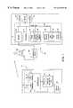
- FIG. 1is a block diagram illustrating a system for collecting GPS data and identifying clusters of stop locations in accordance with the present invention.
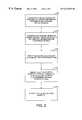
- FIG. 2is a flowchart diagram illustrating the general steps of collecting GPS data and identifying clusters of stop locations according to the present invention.
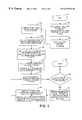
- FIG. 3is a flowchart diagram illustrating the process of a clustering program according to the present invention.
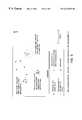
- FIG. 4is a flowchart diagram illustrating a portion of the process of the clustering program in FIG. 3 .
- FIG. 5is a simplified display illustrating identification of clusters of stop locations being implemented according to various parameters.
- FIG. 6is an example of a simplified display presenting results in map format illustrating cluster centers and the number of points in each cluster.
- FIG. 1Disclosed in FIG. 1 is a system for collecting GPS data and identifying clusters of activities according to the present invention.
- movable objectssuch as a vehicle which is generally designated 10 .
- the vehicleis equipped with a global positioning system (GPS) unit 12 for providing location (latitude and longitude) data.
- GPSglobal positioning system
- the GPS unit 12may be configured to provide positional data on a periodic basis; for example, once every minute. Alternatively, the GPS unit 12 may be configured to generate positional data only when the vehicle is parked after reaching its destination.
- the GPS unit 12is in connection with a memory 18 to store positional data 20 .
- a processor(not shown) which controls operations of generating GPS data as well as operations of storing the GPS data into the memory.
- the GPS datamay be time-stamped to indicate a particular time of day at which each set of positional and velocity data is generated.
- the GPS unitmay be operatively coupled to the ignition system 22 of the vehicle to periodically receive information pertaining to the status of the ignition system.
- the GPS unitperiodically receives and records in the memory the following information; the time of day, the latitude and longitude data, velocity information, and the on/off status of the ignition system.
- the wireless network controllersuch as a cellular transceiver 28 , which is connected to a cellular antenna 30 for transmitting and receiving wireless data signals.
- the wireless communications networkmay comprise any suitable network such as a cellular communications network, personal communication systems (PCS), radio frequency communication networks or satellite communications.
- Data signals transmitted over the communications networkare received by a computer 24 .
- a clustering module 46for processing the data received from the GPS units.
- the computer 24is located at a central location 26 and is configured such that the data generated by a number of different GPS units can be processed at the same time.
- the various GPS unitsmay be located in fleet vehicles.
- a wireless communications networkmay be utilized to periodically transfer collected data from the fleet vehicles to the central office 26 .
- the collected datamay be copied onto a data transfer medium such as a magnetic or optical disk and physically carried and loaded onto the computer 24 at the central office.
- the GPS unitmay be configured to automatically establish a wireless connection with the computer 24 at the central office and transmit GPS data at predetermined time intervals; for example, once every hour.
- the GPS unitmay be configured to transmit accumulated data once the vehicle is parked with the ignition off.
- the GPS unitis preferably programmed to collect at least one positional reading after the ignition is deactivated so as to ensure that at least one GPS data point corresponds to the parked location.
- the computer 24 at the central office 26may be any computer capable of performing sequential program execution, including personal computers, minicomputers or mainframes.
- the computer 24includes a system bus 32 to which various components are coupled, such as a modem 34 for establishing a data connection with the GPS unit via a wireless communications network.
- the wireless communication networkincludes a wireless tower 100 for receiving wireless signals and relaying the received signals to a telephonic network 102 , which routes the signals to the modem.
- the computer 24also includes a processor 36 and a memory device 38 which stores, among other things, the GPS data 40 provided by the GPS unit 12 .
- the memory device 38may be any suitable storage device such as a hard drive, floppy disk drive, tape unit, CD-ROM and the like.
- Connected to the processor 36is a random access memory (RAM) 42 into which an operating system 44 and the grouping program of the invention are loaded.
- RAMrandom access memory
- Also connected to the system bus 32are input devices such as a keyboard 48 and a mouse 50 and a display unit 52 .
- field representativesmay use fleet vehicles to move from one destination to another.
- Each of the destinationsmay correspond to the location where the requested service is to be performed or the location where a work break is taken.
- the GPS units in the vehiclesare used to generate positional and/or velocity information and periodically transmit the data to the central office, where the data is analyzed.
- the computer 24 at the central officeprocesses the GPS information to identify stop locations or stationary segments.
- the identification of stop locations or stationary segmentsmay be accomplished using any suitable method.
- One exemplary method of identifying stationary segmentsis described in a co-pending U.S. application Ser. No. 09/386,756, filed Aug. 31, 1999 to Vincil C. Dean, entitled “System and method for grouping GPS data into moving and stationary segments,” which is incorporated herein by reference.
- a list of frequent stops occurring within a close distance from each other or “hot spots” location points which have been visited often by fleet vehicles within a given period of timemay provide useful insight into behavior and habits of field technicians, or possible trouble spots in remote facilities. Because fleet vehicles don't always park in the same place, and because there may be some error in the GPS positions, the hot spot may not be a single point in space, but rather a fuzzy region.
- the present inventionuses the latitude and longitude of every stop to identify “clusters” of points that are within a defined distance from each other to be considered a single hot spot.
- step 200the GPS receiver 14 is used to generate positional and velocity data on a periodic basis.
- the data collected by the GPS receiver 14is transferred to the computer 24 at the central office 26 in step 210 .
- step 220the computer 24 then processes the GPS data to identify stop locations that were visited by field representatives during a predefined period of time.
- the identification of the stop locationsmay be determined based on several variables, such as vehicle speed, traveled distance between two data points, on/off status of ignition system 22 , and duration of stationary time interval.
- step 240the clusters identified are displayed in a map format or printed in a report format.
- Step 230is performed by clustering module 46 .
- FIG. 3is a flowchart diagram of a clustering program according to the present invention.
- the execution of the clustering programbegins at step 310 , where the application program reads the stop locations stored in memory into an array of input points.
- Each input point in the arrayrepresents a geographic location of a stop identified in step 220 of FIG. 2 .
- the coordinates of stop locationsmay be provided in longitude and latitude expressed in the form of degrees.
- the stop locationsmay be converted to x, y coordinates before they are read into the array of input points.
- the method of converting longitude and latitude data to the form of x, y coordinatesis well known in the art.
- the described input pointsare expressed in the form of x, y coordinates to illustrate the principles of the present invention, it will be understood by those skilled in the art that the input point may be expressed in other format including in degrees.
- step 315the clustering program proceeds by sorting the input points according to their locations, e.g., by increasing x-coordinate of the input points.
- step 320every input point in the array is compared against a list of locations to ignore.
- the ignore locationsmay be, for example, parking areas where the fleet vehicles are parked after working hours and other locations such as the location where equipment and parts are picked up. Every input point that lies within a maximum distance tolerance “MAXDIST1” of any ignore location is removed from further consideration in the clustering process (step 330 ).
- the MAXDIST1is a predefined value, for example, specified in feet, i.e., 100 feet, to represent a distance between a stop location and any ignore locations within which such stop location is considered unimportant and removed from the array.
- the input pointsare examined sequentially, linking each input point with all of the other input points that lie close enough to be considered neighbors. This process is continued until linked lists associated with each of the input points are generated.
- the clustering programproceeds in a loop (steps 350 - 380 ) to identify clusters of input points in a descending order of cluster size. Prior to the execution of this loop, all remaining input points are initially considered unmarked including the neighboring input points that are contained in the linked lists (step 345 ). Each time a cluster is identified, the input points associated with the identified cluster become marked serving to indicate that the marked input points have already been included in one of the identified clusters.
- the loopstarts by selecting an (unmarked) input point with the largest number of neighbors in step 350 .
- the number of neighbors associated with the input pointis compared against a minimum number of neighbors criterion (“NMIN”).
- NMINis a predetermined number, representing a minimum number of neighbors necessary to constitute a cluster. If the selected input point has at least NMIN neighbors (step 360 , YES), the selected input point is the center point of a cluster and all its neighbors are recognized as members of the cluster (step 370 ) by recording the center point and number of input points associated with this cluster.
- step 380each of the input points associated with the recognized cluster is marked in the corresponding linked lists so that the marked input points will be ignored during search for subsequent clusters. Additionally in step 380 , the number of neighbors associated with each of the remaining input points is revised to reflect only the remaining unclustered (unmarked) input points (step 380 ).
- the programreturns to the beginning of this loop (step 350 ) where an input point with the largest number of (unmarked) neighboring input points is selected. This process of identifying clusters is continued until there are no more input points with at least NMIN neighbors (step 360 , NO).
- step 340 of FIG. 3is shown.
- step 340 of FIG. 3begins at step 400 in FIG. 4 .
- a counter Nis initialized; i.e., the counter is set to zero (step 410 ).
- the clustering programproceeds in a main-loop (steps 420 - 470 ) to generate a linked list of neighbors for each of the remaining input points sequentially.
- the main-loopcomprises a series of steps to determine which of the other remaining input points are located within a predetermined distance to be considered a neighbor.
- a sub-loop(steps 440 - 470 ) which compares the location of the current input point(N) to the location of each of the following input points sequentially to determine if the input point(X) resides within a predetermined distance “MAXDIST2” from the input point(N) (step 440 ).
- the MAXDIST2is a predefined value, for example, specified in feet, i.e., 100 feet, to represent a distance between two stop locations within which such stop locations are close enough to be considered a neighbor.
- a counter Xis incremented by one and proceeds to the next remaining input point(X).
- corresponding entriesare made in the linked lists of neighboring input points (step 450 ), which include entering input point (X) as one of the input point(N)'s neighboring input points as well as entering input point (N) as one of the input point(X)'s neighboring input points.
- This sub-loopworks its way through the array of input points which is sorted by x-coordinate (step 335 in FIG. 3 ).
- Each input point following the current input point(N)is examined individually until an input point(X) having an x-coordinate greater than XCURRENT plus MAXDIST2 is reached (step 470 , YES), where XCURRENT equals the x-coordinate of the current input point(N). Because the input points are sorted by x-coordinate, it is not necessary to examine input points that follow the first input point(X) with x-coordinate that is further than MAXDIST2 from XCURRENT.
- the execution time required to identify the linked lists of neighbors for each individual input pointis substantially reduced.
- the clustering moduleproceeds at the top of the main-loop step 420 .
- the counter Nincrements its count by one and proceeds to the next input point.
- the main-loop(steps 420470 ) is continued until end of the input points is reached (step 430 , NO) and terminates in step 480 .
- the clustering moduleresumes to step 350 in FIG. 3 .
- the output results of the clustering programare stored in the memory which includes the number of clusters identified and location of the center point and number of input points associated with each cluster.
- the output resultsmay be presented either in map display format or text format. As seen by referring to FIG. 6, the output results can be displayed in an easily comprehensible way in the map display format, so that the clusters of activities can be readily observed by a user to facilitate spotting problems or unusual behavior of the field agents.
- the output resultsare graphically displayed on the display screen using map images stored in the computer memory. An appropriate map image is first selected based on the locations to which the associated vehicles traveled. The selected portion of the map image is then retrieved and displayed on the display screen, so that symbols or icons representing the location of each cluster may be displayed on the map image.
- the cluster symbols or iconsmay be labeled with the location of the center point and number of input points associated with each cluster. Other significant information can also be symbolically displayed with the map image, such as locations of job assignments that were dispatched during the same period of time.
- the map formatenables a user to observe which clusters are located closely to job assignments and which clusters are not associated with any of the job assignments.
- the location of center point and number of input points associated with each of the clusters identifiedmay be presented to a user.
- the programmay be configured to report the location and brief description of such job assignment.
- the text formatmay contain detailed information about each of the identified clusters, such as names of field representatives and arrival and departure time associated with each of the corresponding input points.
- FIG. 5shows identification of clusters of stop locations being implemented according to various parameters.
- the clustering programmay further include a user interface which allows for selection and modification of the predetermined parameters, such as MAXDIST1, MAXDIST2, and NMIN.
- the user interfacemay be configured to allow a user to add or modify ignore locations so that only the location information which is relevant for clustering analysis is considered. In this way, a user may adjust the parameter values such that the output results obtained from the clustering program provide the most useful results.
- the user interfacemay also be configured to permit the user to select the way in which the output results are presented.
- the present systemhas application to substantially any situation where the number of activities occurring within certain geographic location areas may provide a planner with useful insight as to find ways to optimize future operations.
- the present systemmay be used in a variety of industries, including telecommunications and other facilities-based utilities, and other dispatch-oriented operations such as police, taxi, medical and delivery services.
Landscapes
- Physics & Mathematics (AREA)
- General Physics & Mathematics (AREA)
- Navigation (AREA)
- Traffic Control Systems (AREA)
Abstract
Description
Claims (32)
Priority Applications (1)
| Application Number | Priority Date | Filing Date | Title |
|---|---|---|---|
| US09/386,757US6232915B1 (en) | 1999-08-31 | 1999-08-31 | System and method for identifying clusters of geographic locations |
Applications Claiming Priority (1)
| Application Number | Priority Date | Filing Date | Title |
|---|---|---|---|
| US09/386,757US6232915B1 (en) | 1999-08-31 | 1999-08-31 | System and method for identifying clusters of geographic locations |
Publications (1)
| Publication Number | Publication Date |
|---|---|
| US6232915B1true US6232915B1 (en) | 2001-05-15 |
Family
ID=23526929
Family Applications (1)
| Application Number | Title | Priority Date | Filing Date |
|---|---|---|---|
| US09/386,757Expired - LifetimeUS6232915B1 (en) | 1999-08-31 | 1999-08-31 | System and method for identifying clusters of geographic locations |
Country Status (1)
| Country | Link |
|---|---|
| US (1) | US6232915B1 (en) |
Cited By (38)
| Publication number | Priority date | Publication date | Assignee | Title |
|---|---|---|---|---|
| US20030084125A1 (en)* | 2001-10-31 | 2003-05-01 | Nagda Paresh L. | Integrated information exchange system for matching shipping demands and carrier availability |
| EP1376058A3 (en)* | 2002-06-27 | 2004-02-25 | Navigation Technologies Corporation | Method of collecting market research information |
| US20040125763A1 (en)* | 2002-12-05 | 2004-07-01 | Galetti Ralph R. | Serial port multiplexing protocol |
| US20040172194A1 (en)* | 2003-02-28 | 2004-09-02 | Yazaki Corporation | Running route acquiring system and arrival notifying system for touring bus |
| US20040203400A1 (en)* | 2002-12-05 | 2004-10-14 | Galetti Ralph R. | Communications protocol for mobile device |
| US20040203952A1 (en)* | 2002-12-05 | 2004-10-14 | Galetti Ralph R. | Programmable messages for communication system having one-button user interface |
| US6816784B1 (en)* | 2002-03-08 | 2004-11-09 | Navteq North America, Llc | Method and system using delivery trucks to collect address location data |
| US20050143909A1 (en)* | 2003-12-31 | 2005-06-30 | Orwant Jonathan L. | Technique for collecting and using information about the geographic position of a mobile object on the earth's surface |
| US20050273255A1 (en)* | 2004-05-24 | 2005-12-08 | General Motors Corporation | Method and system for programmable mobile vehicle hotspots |
| US6982656B1 (en)* | 2002-12-20 | 2006-01-03 | Innovative Processing Solutions, Llc | Asset monitoring and tracking system |
| US7092964B1 (en) | 2001-06-22 | 2006-08-15 | Navteq North America, Llc | Method of collecting market research information |
| US20070106784A1 (en)* | 2005-11-08 | 2007-05-10 | Dickman David T | Systems, methods and apparatus to identify network maintenance zones |
| WO2008054272A1 (en) | 2006-10-30 | 2008-05-08 | Telefonaktiebolaget Lm Ericsson (Publ) | Extended clustering for improved positioning |
| US20080125968A1 (en)* | 2006-11-27 | 2008-05-29 | Thomas Michael Bradicich | Apparatus, system, and method for autonomously determining a set of destinations |
| US20080147473A1 (en)* | 2002-08-22 | 2008-06-19 | United Parcel Service Of America | Core area territory planning for optimizing driver familiarity and route flexibility |
| US20080255758A1 (en)* | 2007-04-13 | 2008-10-16 | United Parcel Service Of America, Inc. | Systems, methods, and computer program products for generating reference geocodes for point addresses |
| US20100169004A1 (en)* | 2008-12-26 | 2010-07-01 | Sony Corporation | Information processing apparatus, information processing method and program |
| US20110112761A1 (en)* | 2009-11-09 | 2011-05-12 | United Parcel Service Of America, Inc. | Enhanced Location Information For Points of Interest |
| US20110176494A1 (en)* | 2010-01-15 | 2011-07-21 | Huang Ronald K | Location Filtering Using Mobile Country Code |
| US20110177825A1 (en)* | 2010-01-15 | 2011-07-21 | Huang Ronald K | Location determination using cached location area codes |
| US20110177831A1 (en)* | 2010-01-15 | 2011-07-21 | Huang Ronald K | Determining a location of a mobile device using a location database |
| US20110177832A1 (en)* | 2010-01-15 | 2011-07-21 | Huang Ronald K | Adaptive Location Determination |
| US20110177826A1 (en)* | 2010-01-15 | 2011-07-21 | Huang Ronald K | Location determination using cached location area codes |
| US20110176523A1 (en)* | 2010-01-15 | 2011-07-21 | Huang Ronald K | Managing a location database for network-based positioning system |
| US8538458B2 (en) | 2005-04-04 | 2013-09-17 | X One, Inc. | Location sharing and tracking using mobile phones or other wireless devices |
| US8620344B2 (en) | 2010-04-07 | 2013-12-31 | Apple Inc. | Location-based application program management |
| US8949397B2 (en) | 2009-10-14 | 2015-02-03 | Blackberry Limited | Maintenance methods, devices and systems for mobile communications system |
| WO2016061631A1 (en)* | 2014-10-23 | 2016-04-28 | South East Water Corporation | Systems and computer implemented methods for monitoring an activity at one or more facilities |
| US9631938B2 (en)* | 2015-08-02 | 2017-04-25 | Baruch AXELROD | Route planning system and method |
| US9928749B2 (en) | 2016-04-29 | 2018-03-27 | United Parcel Service Of America, Inc. | Methods for delivering a parcel to a restricted access area |
| US20180232397A1 (en)* | 2017-02-15 | 2018-08-16 | Uber Technologies, Inc. | Geospatial clustering for service coordination systems |
| US10417601B2 (en) | 2013-06-28 | 2019-09-17 | United Parcel Service Of America, Inc. | Confidence ratings for delivery of items |
| US10730626B2 (en) | 2016-04-29 | 2020-08-04 | United Parcel Service Of America, Inc. | Methods of photo matching and photo confirmation for parcel pickup and delivery |
| US10775792B2 (en) | 2017-06-13 | 2020-09-15 | United Parcel Service Of America, Inc. | Autonomously delivering items to corresponding delivery locations proximate a delivery route |
| US10936917B2 (en) | 2017-01-31 | 2021-03-02 | Verizon Connect Ireland Limited | System and method for detecting and classifying recurrent stops of a vehicle fleet |
| CN113961657A (en)* | 2021-10-15 | 2022-01-21 | 北京中交兴路信息科技有限公司 | A vehicle fleet identification method, device, computer equipment and storage medium |
| US20240020945A1 (en)* | 2022-07-15 | 2024-01-18 | Nielsen Consumer Llc | Methods, systems, articles of manufacture and apparatus for clustering vertices of an n-dimensional regular polygon using bearing angles |
| US12354031B2 (en) | 2017-09-29 | 2025-07-08 | United Parcel Service Of America, Inc. | Predictive parcel damage identification, analysis, and mitigation |
Citations (1)
| Publication number | Priority date | Publication date | Assignee | Title |
|---|---|---|---|---|
| US5919239A (en)* | 1996-06-28 | 1999-07-06 | Fraker; William F. | Position and time-at-position logging system |
- 1999
- 1999-08-31USUS09/386,757patent/US6232915B1/ennot_activeExpired - Lifetime
Patent Citations (1)
| Publication number | Priority date | Publication date | Assignee | Title |
|---|---|---|---|---|
| US5919239A (en)* | 1996-06-28 | 1999-07-06 | Fraker; William F. | Position and time-at-position logging system |
Cited By (129)
| Publication number | Priority date | Publication date | Assignee | Title |
|---|---|---|---|---|
| US7092964B1 (en) | 2001-06-22 | 2006-08-15 | Navteq North America, Llc | Method of collecting market research information |
| US20030084125A1 (en)* | 2001-10-31 | 2003-05-01 | Nagda Paresh L. | Integrated information exchange system for matching shipping demands and carrier availability |
| US6990409B2 (en) | 2002-03-08 | 2006-01-24 | Navteq North America, Llc. | Method and system using delivery trucks to collect address location data |
| US6816784B1 (en)* | 2002-03-08 | 2004-11-09 | Navteq North America, Llc | Method and system using delivery trucks to collect address location data |
| US20050065719A1 (en)* | 2002-03-08 | 2005-03-24 | Khan M. Salahuddin | Method and system using delivery trucks to collect address location data |
| EP1376058A3 (en)* | 2002-06-27 | 2004-02-25 | Navigation Technologies Corporation | Method of collecting market research information |
| US20100088146A1 (en)* | 2002-08-22 | 2010-04-08 | United Parcel Service Of America, Inc. | Core Area Territory Planning for Optimizing Driver Familiarity and Route Flexibility |
| US20080147473A1 (en)* | 2002-08-22 | 2008-06-19 | United Parcel Service Of America | Core area territory planning for optimizing driver familiarity and route flexibility |
| US7840319B2 (en) | 2002-08-22 | 2010-11-23 | United Parcel Service Of America, Inc. | Core area territory planning for optimizing driver familiarity and route flexibility |
| US7660651B2 (en)* | 2002-08-22 | 2010-02-09 | United Parcel Service Of America, Inc. | Core area territory planning for optimizing driver familiarity and route flexibility |
| US7310533B2 (en) | 2002-12-05 | 2007-12-18 | The Boeing Company | Programmable messages for communication system having one-button user interface |
| US7269429B2 (en)* | 2002-12-05 | 2007-09-11 | The Boeing Company | Communications protocol for mobile device |
| US20040203952A1 (en)* | 2002-12-05 | 2004-10-14 | Galetti Ralph R. | Programmable messages for communication system having one-button user interface |
| US20040203400A1 (en)* | 2002-12-05 | 2004-10-14 | Galetti Ralph R. | Communications protocol for mobile device |
| US20040125763A1 (en)* | 2002-12-05 | 2004-07-01 | Galetti Ralph R. | Serial port multiplexing protocol |
| US7626958B2 (en)* | 2002-12-05 | 2009-12-01 | The Boeing Company | Serial port multiplexing protocol |
| US6982656B1 (en)* | 2002-12-20 | 2006-01-03 | Innovative Processing Solutions, Llc | Asset monitoring and tracking system |
| US20080065324A1 (en)* | 2003-02-28 | 2008-03-13 | Harushi Muramatsu | Running route acquiring system and arrival notifying system for touring bus |
| US8224563B2 (en) | 2003-02-28 | 2012-07-17 | Yazaki Corporation | Running route acquiring system and arrival notifying system for touring bus |
| US20040172194A1 (en)* | 2003-02-28 | 2004-09-02 | Yazaki Corporation | Running route acquiring system and arrival notifying system for touring bus |
| US20050143909A1 (en)* | 2003-12-31 | 2005-06-30 | Orwant Jonathan L. | Technique for collecting and using information about the geographic position of a mobile object on the earth's surface |
| US20050273255A1 (en)* | 2004-05-24 | 2005-12-08 | General Motors Corporation | Method and system for programmable mobile vehicle hotspots |
| US9883360B1 (en) | 2005-04-04 | 2018-01-30 | X One, Inc. | Rendez vous management using mobile phones or other mobile devices |
| US10149092B1 (en) | 2005-04-04 | 2018-12-04 | X One, Inc. | Location sharing service between GPS-enabled wireless devices, with shared target location exchange |
| US9467832B2 (en) | 2005-04-04 | 2016-10-11 | X One, Inc. | Methods and systems for temporarily sharing position data between mobile-device users |
| US9615204B1 (en) | 2005-04-04 | 2017-04-04 | X One, Inc. | Techniques for communication within closed groups of mobile devices |
| US9253616B1 (en) | 2005-04-04 | 2016-02-02 | X One, Inc. | Apparatus and method for obtaining content on a cellular wireless device based on proximity |
| US9654921B1 (en) | 2005-04-04 | 2017-05-16 | X One, Inc. | Techniques for sharing position data between first and second devices |
| US11778415B2 (en) | 2005-04-04 | 2023-10-03 | Xone, Inc. | Location sharing application in association with services provision |
| US9185522B1 (en) | 2005-04-04 | 2015-11-10 | X One, Inc. | Apparatus and method to transmit content to a cellular wireless device based on proximity to other wireless devices |
| US11356799B2 (en) | 2005-04-04 | 2022-06-07 | X One, Inc. | Fleet location sharing application in association with services provision |
| US10856099B2 (en) | 2005-04-04 | 2020-12-01 | X One, Inc. | Application-based two-way tracking and mapping function with selected individuals |
| US10791414B2 (en) | 2005-04-04 | 2020-09-29 | X One, Inc. | Location sharing for commercial and proprietary content applications |
| US10750310B2 (en) | 2005-04-04 | 2020-08-18 | X One, Inc. | Temporary location sharing group with event based termination |
| US10750309B2 (en) | 2005-04-04 | 2020-08-18 | X One, Inc. | Ad hoc location sharing group establishment for wireless devices with designated meeting point |
| US10750311B2 (en) | 2005-04-04 | 2020-08-18 | X One, Inc. | Application-based tracking and mapping function in connection with vehicle-based services provision |
| US10341808B2 (en) | 2005-04-04 | 2019-07-02 | X One, Inc. | Location sharing for commercial and proprietary content applications |
| US10341809B2 (en) | 2005-04-04 | 2019-07-02 | X One, Inc. | Location sharing with facilitated meeting point definition |
| US9167558B2 (en) | 2005-04-04 | 2015-10-20 | X One, Inc. | Methods and systems for sharing position data between subscribers involving multiple wireless providers |
| US9736618B1 (en) | 2005-04-04 | 2017-08-15 | X One, Inc. | Techniques for sharing relative position between mobile devices |
| US10313826B2 (en) | 2005-04-04 | 2019-06-04 | X One, Inc. | Location sharing and map support in connection with services request |
| US9749790B1 (en) | 2005-04-04 | 2017-08-29 | X One, Inc. | Rendez vous management using mobile phones or other mobile devices |
| US9031581B1 (en) | 2005-04-04 | 2015-05-12 | X One, Inc. | Apparatus and method for obtaining content on a cellular wireless device based on proximity to other wireless devices |
| US10299071B2 (en) | 2005-04-04 | 2019-05-21 | X One, Inc. | Server-implemented methods and systems for sharing location amongst web-enabled cell phones |
| US10200811B1 (en) | 2005-04-04 | 2019-02-05 | X One, Inc. | Map presentation on cellular device showing positions of multiple other wireless device users |
| US8538458B2 (en) | 2005-04-04 | 2013-09-17 | X One, Inc. | Location sharing and tracking using mobile phones or other wireless devices |
| US9854394B1 (en) | 2005-04-04 | 2017-12-26 | X One, Inc. | Ad hoc location sharing group between first and second cellular wireless devices |
| US10165059B2 (en) | 2005-04-04 | 2018-12-25 | X One, Inc. | Methods, systems and apparatuses for the formation and tracking of location sharing groups |
| US8831635B2 (en) | 2005-04-04 | 2014-09-09 | X One, Inc. | Methods and apparatuses for transmission of an alert to multiple devices |
| US8798593B2 (en) | 2005-04-04 | 2014-08-05 | X One, Inc. | Location sharing and tracking using mobile phones or other wireless devices |
| US9967704B1 (en) | 2005-04-04 | 2018-05-08 | X One, Inc. | Location sharing group map management |
| US9955298B1 (en) | 2005-04-04 | 2018-04-24 | X One, Inc. | Methods, systems and apparatuses for the formation and tracking of location sharing groups |
| US9942705B1 (en) | 2005-04-04 | 2018-04-10 | X One, Inc. | Location sharing group for services provision |
| US8712441B2 (en) | 2005-04-04 | 2014-04-29 | Xone, Inc. | Methods and systems for temporarily sharing position data between mobile-device users |
| US9584960B1 (en) | 2005-04-04 | 2017-02-28 | X One, Inc. | Rendez vous management using mobile phones or other mobile devices |
| US9854402B1 (en) | 2005-04-04 | 2017-12-26 | X One, Inc. | Formation of wireless device location sharing group |
| US8750898B2 (en) | 2005-04-04 | 2014-06-10 | X One, Inc. | Methods and systems for annotating target locations |
| US8798645B2 (en) | 2005-04-04 | 2014-08-05 | X One, Inc. | Methods and systems for sharing position data and tracing paths between mobile-device users |
| US8798647B1 (en) | 2005-04-04 | 2014-08-05 | X One, Inc. | Tracking proximity of services provider to services consumer |
| US20070106784A1 (en)* | 2005-11-08 | 2007-05-10 | Dickman David T | Systems, methods and apparatus to identify network maintenance zones |
| WO2008054272A1 (en) | 2006-10-30 | 2008-05-08 | Telefonaktiebolaget Lm Ericsson (Publ) | Extended clustering for improved positioning |
| EP2078436A4 (en)* | 2006-10-30 | 2014-01-22 | Ericsson Telefon Ab L M | Extended clustering for improved positioning |
| US20080125968A1 (en)* | 2006-11-27 | 2008-05-29 | Thomas Michael Bradicich | Apparatus, system, and method for autonomously determining a set of destinations |
| US8566028B2 (en)* | 2006-11-27 | 2013-10-22 | International Business Machines Corporation | Apparatus, system, and method for autonomously determining a set of destinations |
| US7953547B2 (en) | 2007-04-13 | 2011-05-31 | United Parcel Service Of America, Inc. | Systems, methods, and computer program products for generating reference geocodes for point addresses |
| US8065076B2 (en) | 2007-04-13 | 2011-11-22 | United Parcel Service Of America, Inc. | Systems, methods, and computer program products for generating reference geocodes for point addresses |
| US20110208751A1 (en)* | 2007-04-13 | 2011-08-25 | Craig Graham | Systems, Methods, and Computer Program Products For Generating Reference Geocodes For Point Addresses |
| US20110040696A1 (en)* | 2007-04-13 | 2011-02-17 | United Parcel Service Of America, Inc. | Systems, Methods, and Computer Program Products for Generating Reference Geocodes for Point Addresses |
| US7840340B2 (en) | 2007-04-13 | 2010-11-23 | United Parcel Service Of America, Inc. | Systems, methods, and computer program products for generating reference geocodes for point addresses |
| US20080255758A1 (en)* | 2007-04-13 | 2008-10-16 | United Parcel Service Of America, Inc. | Systems, methods, and computer program products for generating reference geocodes for point addresses |
| US8392389B2 (en)* | 2008-12-26 | 2013-03-05 | Sony Corporation | Combined location and frequency information processing apparatus, method, and program |
| US20100169004A1 (en)* | 2008-12-26 | 2010-07-01 | Sony Corporation | Information processing apparatus, information processing method and program |
| US8949397B2 (en) | 2009-10-14 | 2015-02-03 | Blackberry Limited | Maintenance methods, devices and systems for mobile communications system |
| US8972165B2 (en) | 2009-11-09 | 2015-03-03 | United Parcel Service Of America, Inc. | Enhanced location information for points of interest |
| US8655487B2 (en) | 2009-11-09 | 2014-02-18 | United Parcel Service Of America, Inc. | Enhanced location information for points of interest |
| US8849563B2 (en) | 2009-11-09 | 2014-09-30 | United Parcel Service Of America, Inc. | Enhanced location information for points of interest |
| US8751153B2 (en) | 2009-11-09 | 2014-06-10 | United Parcel Service Of America, Inc. | Enhanced location information for points of interest |
| US8725407B2 (en) | 2009-11-09 | 2014-05-13 | United Parcel Service Of America, Inc. | Enhanced location information for points of interest |
| US9082100B2 (en) | 2009-11-09 | 2015-07-14 | United Parcel Service Of America, Inc. | Enhanced location information for points of interest |
| US20110172910A1 (en)* | 2009-11-09 | 2011-07-14 | Shawn Patrick Hurley | Enhanced location information for points of interest |
| US20110172911A1 (en)* | 2009-11-09 | 2011-07-14 | Shawn Patrick Hurley | Enhanced location information for points of interest |
| US20110112761A1 (en)* | 2009-11-09 | 2011-05-12 | United Parcel Service Of America, Inc. | Enhanced Location Information For Points of Interest |
| US8200251B2 (en) | 2010-01-15 | 2012-06-12 | Apple Inc. | Determining a location of a mobile device using a location database |
| US20110177832A1 (en)* | 2010-01-15 | 2011-07-21 | Huang Ronald K | Adaptive Location Determination |
| US20110177831A1 (en)* | 2010-01-15 | 2011-07-21 | Huang Ronald K | Determining a location of a mobile device using a location database |
| US20110177825A1 (en)* | 2010-01-15 | 2011-07-21 | Huang Ronald K | Location determination using cached location area codes |
| US8655371B2 (en) | 2010-01-15 | 2014-02-18 | Apple Inc. | Location determination using cached location area codes |
| US9119168B2 (en) | 2010-01-15 | 2015-08-25 | Apple Inc. | Managing a location database for network-based positioning system |
| US20110176494A1 (en)* | 2010-01-15 | 2011-07-21 | Huang Ronald K | Location Filtering Using Mobile Country Code |
| US20110177826A1 (en)* | 2010-01-15 | 2011-07-21 | Huang Ronald K | Location determination using cached location area codes |
| US8634860B2 (en) | 2010-01-15 | 2014-01-21 | Apple Inc. | Location determination using cached location area codes |
| US20110176523A1 (en)* | 2010-01-15 | 2011-07-21 | Huang Ronald K | Managing a location database for network-based positioning system |
| US8504059B2 (en) | 2010-01-15 | 2013-08-06 | Apple Inc. | Location filtering using mobile country code |
| US8660576B2 (en) | 2010-01-15 | 2014-02-25 | Apple Inc. | Adaptive location determination |
| US8433334B2 (en) | 2010-01-15 | 2013-04-30 | Apple Inc. | Managing a location database for network-based positioning system |
| US9210529B2 (en) | 2010-04-07 | 2015-12-08 | Apple Inc. | Location-based application program management |
| US8620344B2 (en) | 2010-04-07 | 2013-12-31 | Apple Inc. | Location-based application program management |
| US10417601B2 (en) | 2013-06-28 | 2019-09-17 | United Parcel Service Of America, Inc. | Confidence ratings for delivery of items |
| US11501242B2 (en) | 2013-06-28 | 2022-11-15 | United Parcel Service Of America, Inc. | Confidence ratings for delivery of items |
| US12210996B2 (en) | 2013-06-28 | 2025-01-28 | United Parcel Service Of America, Inc. | Confidence ratings for delivery of items |
| US11100472B2 (en) | 2014-10-23 | 2021-08-24 | South East Water Corporation | Systems and computer implemented methods for monitoring an activity at one or more facilities |
| WO2016061631A1 (en)* | 2014-10-23 | 2016-04-28 | South East Water Corporation | Systems and computer implemented methods for monitoring an activity at one or more facilities |
| US9631938B2 (en)* | 2015-08-02 | 2017-04-25 | Baruch AXELROD | Route planning system and method |
| US10460281B2 (en) | 2016-04-29 | 2019-10-29 | United Parcel Service Of America, Inc. | Delivery vehicle including an unmanned aerial vehicle support mechanism |
| US9957048B2 (en) | 2016-04-29 | 2018-05-01 | United Parcel Service Of America, Inc. | Unmanned aerial vehicle including a removable power source |
| US10730626B2 (en) | 2016-04-29 | 2020-08-04 | United Parcel Service Of America, Inc. | Methods of photo matching and photo confirmation for parcel pickup and delivery |
| US10706382B2 (en) | 2016-04-29 | 2020-07-07 | United Parcel Service Of America, Inc. | Delivery vehicle including an unmanned aerial vehicle loading robot |
| US10586201B2 (en) | 2016-04-29 | 2020-03-10 | United Parcel Service Of America, Inc. | Methods for landing an unmanned aerial vehicle |
| US10482414B2 (en) | 2016-04-29 | 2019-11-19 | United Parcel Service Of America, Inc. | Unmanned aerial vehicle chassis |
| US9928749B2 (en) | 2016-04-29 | 2018-03-27 | United Parcel Service Of America, Inc. | Methods for delivering a parcel to a restricted access area |
| US10453022B2 (en) | 2016-04-29 | 2019-10-22 | United Parcel Service Of America, Inc. | Unmanned aerial vehicle and landing system |
| US10796269B2 (en) | 2016-04-29 | 2020-10-06 | United Parcel Service Of America, Inc. | Methods for sending and receiving notifications in an unmanned aerial vehicle delivery system |
| US10202192B2 (en) | 2016-04-29 | 2019-02-12 | United Parcel Service Of America, Inc. | Methods for picking up a parcel via an unmanned aerial vehicle |
| US10860971B2 (en) | 2016-04-29 | 2020-12-08 | United Parcel Service Of America, Inc. | Methods for parcel delivery and pickup via an unmanned aerial vehicle |
| US10726381B2 (en) | 2016-04-29 | 2020-07-28 | United Parcel Service Of America, Inc. | Methods for dispatching unmanned aerial delivery vehicles |
| US9969495B2 (en) | 2016-04-29 | 2018-05-15 | United Parcel Service Of America, Inc. | Unmanned aerial vehicle pick-up and delivery systems |
| US11472552B2 (en) | 2016-04-29 | 2022-10-18 | United Parcel Service Of America, Inc. | Methods of photo matching and photo confirmation for parcel pickup and delivery |
| US9981745B2 (en) | 2016-04-29 | 2018-05-29 | United Parcel Service Of America, Inc. | Unmanned aerial vehicle including a removable parcel carrier |
| US11514276B2 (en) | 2017-01-31 | 2022-11-29 | Verizon Connect Development Limited | System and method for detecting and classifying recurrent stops of a vehicle fleet |
| US10936917B2 (en) | 2017-01-31 | 2021-03-02 | Verizon Connect Ireland Limited | System and method for detecting and classifying recurrent stops of a vehicle fleet |
| US20180232397A1 (en)* | 2017-02-15 | 2018-08-16 | Uber Technologies, Inc. | Geospatial clustering for service coordination systems |
| US11435744B2 (en) | 2017-06-13 | 2022-09-06 | United Parcel Service Of America, Inc. | Autonomously delivering items to corresponding delivery locations proximate a delivery route |
| US10775792B2 (en) | 2017-06-13 | 2020-09-15 | United Parcel Service Of America, Inc. | Autonomously delivering items to corresponding delivery locations proximate a delivery route |
| US12416919B2 (en) | 2017-06-13 | 2025-09-16 | United Parcel Service Of America, Inc. | Autonomously delivering items to corresponding delivery locations proximate a delivery route |
| US12354031B2 (en) | 2017-09-29 | 2025-07-08 | United Parcel Service Of America, Inc. | Predictive parcel damage identification, analysis, and mitigation |
| CN113961657A (en)* | 2021-10-15 | 2022-01-21 | 北京中交兴路信息科技有限公司 | A vehicle fleet identification method, device, computer equipment and storage medium |
| CN113961657B (en)* | 2021-10-15 | 2025-08-08 | 北京兴路车联科技有限公司 | A fleet identification method, device, computer equipment and storage medium |
| US20240020945A1 (en)* | 2022-07-15 | 2024-01-18 | Nielsen Consumer Llc | Methods, systems, articles of manufacture and apparatus for clustering vertices of an n-dimensional regular polygon using bearing angles |
| US12361676B2 (en)* | 2022-07-15 | 2025-07-15 | Nielsen Consumer Llc | Methods, systems, articles of manufacture and apparatus for clustering vertices of an N-dimensional regular polygon using bearing angles |
Similar Documents
| Publication | Publication Date | Title |
|---|---|---|
| US6232915B1 (en) | System and method for identifying clusters of geographic locations | |
| US6609064B1 (en) | System and method for grouping GPS data into moving and stationary segments | |
| US8972179B2 (en) | Method and apparatus to analyze GPS data to determine if a vehicle has adhered to a predetermined route | |
| CN101657697B (en) | Systems, and methods for generating reference geocodes for point addresses | |
| EP1881712B1 (en) | Communication device search system | |
| US6947835B2 (en) | Method for monitoring cellular communication, and system therefor | |
| US7680595B2 (en) | Method and apparatus to utilize GPS data to replace route planning software | |
| US7113864B2 (en) | Fully automated vehicle dispatching, monitoring and billing | |
| US6831563B1 (en) | Location visit confirmation services for wireless devices | |
| EP1193631A2 (en) | Fully automated vehicle dispatching, monitoring and billing | |
| US20060058940A1 (en) | Traffic information prediction system | |
| JP2005115687A (en) | Road maintenance support system | |
| WO2001069176A1 (en) | Method of monitoring vehicular mileage | |
| US20030149607A1 (en) | Information processing technique associated with snow removal | |
| US7236767B1 (en) | Wireless cell site finder and customer service system | |
| CN116828433A (en) | Intelligent patrol management system and method based on Bluetooth beacon | |
| CN118278923B (en) | Operation and maintenance management system and method for rail transit AFC equipment | |
| CN116757348A (en) | Travel information intelligent planning management system and method based on artificial intelligence | |
| US20070167168A1 (en) | Worker-in-charge command system and worker-in-charge command method | |
| JP4120953B2 (en) | Method and apparatus for providing a comprehensive car parking service | |
| WO2011052473A1 (en) | Management server, population information calculation management server, zero population distribution area management method, and population information calculation method | |
| CN100588292C (en) | Symbiosis system for testing electromagnetic signal coverage in areas near transport paths | |
| JP2004318283A (en) | Wireless ID tag monitoring system and method | |
| CN114268404B (en) | Civil aviation GPS interference source positioning and investigation system and method | |
| JP2007214841A (en) | Location information verification device |
Legal Events
| Date | Code | Title | Description |
|---|---|---|---|
| AS | Assignment | Owner name:US WEST, INC., COLORADO Free format text:CORRECTIVE DOCUMENT;ASSIGNORS:DEAN, VINCIL C.;BABAYEV, DJANGIR A.;REEL/FRAME:010490/0188 Effective date:19991221 | |
| AS | Assignment | Owner name:U S WEST, INC., COLORADO Free format text:DOCUMENT PREVIOUSLY RECORDED ON REEL 010561, FRAME 0354 CONTAINED AN ERROR IN PROPERTY 09/386767. DOCUMENT RE-RECORDED TO CORRECT THE ERROR ON STATED REEL.;ASSIGNORS:DEAN, VINCIL C.;BABAYEV, DJANGIR A.;REEL/FRAME:010723/0656 Effective date:19991221 | |
| AS | Assignment | Owner name:QWEST COMMUNICATIONS INTERNATIONAL INC., COLORADO Free format text:MERGER;ASSIGNOR:U S WEST, INC.;REEL/FRAME:010814/0339 Effective date:20000630 | |
| STCF | Information on status: patent grant | Free format text:PATENTED CASE | |
| FPAY | Fee payment | Year of fee payment:4 | |
| FPAY | Fee payment | Year of fee payment:8 | |
| FPAY | Fee payment | Year of fee payment:12 | |
| AS | Assignment | Owner name:BANK OF AMERICA, N.A., AS COLLATERAL AGENT, NORTH CAROLINA Free format text:SECURITY INTEREST;ASSIGNOR:QWEST COMMUNICATIONS INTERNATIONAL INC.;REEL/FRAME:044652/0829 Effective date:20171101 Owner name:BANK OF AMERICA, N.A., AS COLLATERAL AGENT, NORTH Free format text:SECURITY INTEREST;ASSIGNOR:QWEST COMMUNICATIONS INTERNATIONAL INC.;REEL/FRAME:044652/0829 Effective date:20171101 |