US6232555B1 - Crimp connection - Google Patents
Crimp connectionDownload PDFInfo
- Publication number
- US6232555B1 US6232555B1US09/265,615US26561599AUS6232555B1US 6232555 B1US6232555 B1US 6232555B1US 26561599 AUS26561599 AUS 26561599AUS 6232555 B1US6232555 B1US 6232555B1
- Authority
- US
- United States
- Prior art keywords
- ferrule
- crimping
- side plates
- ribs
- crimp connection
- Prior art date
- Legal status (The legal status is an assumption and is not a legal conclusion. Google has not performed a legal analysis and makes no representation as to the accuracy of the status listed.)
- Expired - Lifetime
Links
- 238000002788crimpingMethods0.000claimsabstractdescription40
- 238000009413insulationMethods0.000claimsdescription6
- 239000011324beadSubstances0.000claimsdescription3
- 238000004049embossingMethods0.000claims1
- 238000005096rolling processMethods0.000claims1
- 239000004020conductorSubstances0.000description7
- 239000000463materialSubstances0.000description4
- 238000011161developmentMethods0.000description1
- 230000018109developmental processEffects0.000description1
- 238000000034methodMethods0.000description1
- 230000007704transitionEffects0.000description1
Images


Classifications
- H—ELECTRICITY
- H05—ELECTRIC TECHNIQUES NOT OTHERWISE PROVIDED FOR
- H05K—PRINTED CIRCUITS; CASINGS OR CONSTRUCTIONAL DETAILS OF ELECTRIC APPARATUS; MANUFACTURE OF ASSEMBLAGES OF ELECTRICAL COMPONENTS
- H05K3/00—Apparatus or processes for manufacturing printed circuits
- H05K3/36—Assembling printed circuits with other printed circuits
- H05K3/361—Assembling flexible printed circuits with other printed circuits
- H05K3/365—Assembling flexible printed circuits with other printed circuits by abutting, i.e. without alloying process
- H—ELECTRICITY
- H01—ELECTRIC ELEMENTS
- H01R—ELECTRICALLY-CONDUCTIVE CONNECTIONS; STRUCTURAL ASSOCIATIONS OF A PLURALITY OF MUTUALLY-INSULATED ELECTRICAL CONNECTING ELEMENTS; COUPLING DEVICES; CURRENT COLLECTORS
- H01R4/00—Electrically-conductive connections between two or more conductive members in direct contact, i.e. touching one another; Means for effecting or maintaining such contact; Electrically-conductive connections having two or more spaced connecting locations for conductors and using contact members penetrating insulation
- H01R4/10—Electrically-conductive connections between two or more conductive members in direct contact, i.e. touching one another; Means for effecting or maintaining such contact; Electrically-conductive connections having two or more spaced connecting locations for conductors and using contact members penetrating insulation effected solely by twisting, wrapping, bending, crimping, or other permanent deformation
- H01R4/18—Electrically-conductive connections between two or more conductive members in direct contact, i.e. touching one another; Means for effecting or maintaining such contact; Electrically-conductive connections having two or more spaced connecting locations for conductors and using contact members penetrating insulation effected solely by twisting, wrapping, bending, crimping, or other permanent deformation by crimping
- H01R4/182—Electrically-conductive connections between two or more conductive members in direct contact, i.e. touching one another; Means for effecting or maintaining such contact; Electrically-conductive connections having two or more spaced connecting locations for conductors and using contact members penetrating insulation effected solely by twisting, wrapping, bending, crimping, or other permanent deformation by crimping for flat conductive elements, e.g. flat cables
- H—ELECTRICITY
- H01—ELECTRIC ELEMENTS
- H01R—ELECTRICALLY-CONDUCTIVE CONNECTIONS; STRUCTURAL ASSOCIATIONS OF A PLURALITY OF MUTUALLY-INSULATED ELECTRICAL CONNECTING ELEMENTS; COUPLING DEVICES; CURRENT COLLECTORS
- H01R4/00—Electrically-conductive connections between two or more conductive members in direct contact, i.e. touching one another; Means for effecting or maintaining such contact; Electrically-conductive connections having two or more spaced connecting locations for conductors and using contact members penetrating insulation
- H01R4/10—Electrically-conductive connections between two or more conductive members in direct contact, i.e. touching one another; Means for effecting or maintaining such contact; Electrically-conductive connections having two or more spaced connecting locations for conductors and using contact members penetrating insulation effected solely by twisting, wrapping, bending, crimping, or other permanent deformation
- H01R4/18—Electrically-conductive connections between two or more conductive members in direct contact, i.e. touching one another; Means for effecting or maintaining such contact; Electrically-conductive connections having two or more spaced connecting locations for conductors and using contact members penetrating insulation effected solely by twisting, wrapping, bending, crimping, or other permanent deformation by crimping
- H01R4/20—Electrically-conductive connections between two or more conductive members in direct contact, i.e. touching one another; Means for effecting or maintaining such contact; Electrically-conductive connections having two or more spaced connecting locations for conductors and using contact members penetrating insulation effected solely by twisting, wrapping, bending, crimping, or other permanent deformation by crimping using a crimping sleeve
- H01R4/203—Electrically-conductive connections between two or more conductive members in direct contact, i.e. touching one another; Means for effecting or maintaining such contact; Electrically-conductive connections having two or more spaced connecting locations for conductors and using contact members penetrating insulation effected solely by twisting, wrapping, bending, crimping, or other permanent deformation by crimping using a crimping sleeve having an uneven wire-receiving surface to improve the contact
- H01R4/206—Electrically-conductive connections between two or more conductive members in direct contact, i.e. touching one another; Means for effecting or maintaining such contact; Electrically-conductive connections having two or more spaced connecting locations for conductors and using contact members penetrating insulation effected solely by twisting, wrapping, bending, crimping, or other permanent deformation by crimping using a crimping sleeve having an uneven wire-receiving surface to improve the contact with transversal grooves or threads
Definitions
- the present inventionis based on a crimp connection designed according to the precharacterizing clause of the main claim. It relates in particular to a crimp connection for establishing a connection between two flexible printed-circuit boards, two flexible flat-ribbon lines or else a flexible printed-circuit board and a flexible flat-ribbon cable.
- a crimping ferrulein which the line to be connected is located.
- a crimping toolwhich deforms the crimping ferrule in such a way that a direct (galvanic) contact is established between conductor and crimp connection is generally used.
- a crimp connection corresponding to the precharacterizing clause of the main claimis disclosed by the U.S. Pat. No. 3,696,322.
- a crimp connectionin which the ends of the side plates of this crimping ferrule have serrations which, during crimping, are bent back in a U-shaped manner and are pressed into the conductor and thus produce the contact.
- Such crimp connectionshave the disadvantage that they contact the conductor in a punctiform manner and consequently are designed only for low currents. Furthermore, in particular if the material of the side plates of the crimping ferrules relaxes, this may have the result that the contact between conductor and crimp connection becomes loose over time and finally fails completely.
- the present inventionis based on the object of improving a crimp connection of the type described at the beginning in such a way that it is likewise designed for high current applications and, nevertheless, the connection remains fully serviceable even in the possible event of material fatigue.
- the crimp connectionestablishes a connection between a flexible flat contact part and a crimping ferrule which encloses the latter and has a base and two side plates which extend upwards from the base. Furthermore at least one groove is recessed in the base towards the interior of the ferrule and transversely to the longitudinal ferrule axis. The free ends of the side plates have ribs. After crimping has taken place, the side plates are rolled in towards the interior of the ferrule, with the result that ribs located on the said side plates press the flexible contact part into the corresponding groove. At the same time, the flexible contact part engages essentially positively into the corresponding groove.
- this crimp connectionmay be used for conventional and existing methods of crimping. What is more, because of the spiral-shaped side plates of the crimping ferrules, it is ensured that, in spite of relaxation of the crimping material (material fatigue, relaxation, deformation), the electrical and mechanical properties of the crimping connection are approximately preserved.
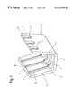
- FIG. 1shows a perspective representation of a crimping ferrule according to the invention
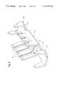
- FIG. 2shows a perspective representation of a second embodiment of a crimping connection according to the invention, with one insulating crimp,
- FIG. 3shows a perspective representation of a third embodiment of a crimp connection according to the invention, with two insulating crimps,
- FIG. 4shows a perspective representation of another embodiment of the crimp connection according to the invention, with two crimping ferrules and two insulating crimps,
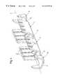
- FIG.shows a perspective representation of a flat-ribbon conductor with insulation-free contacts, on which there are provided crimp connections according to FIG. 2, before and after crimping,
- FIG. 6shows a section through line B—B of FIG. 5, which passes through a rib, the crimp connection being in the crimped state
- FIG. 7shows a section through the line C—C of FIG. 5, which runs between the ribs, the crimp connection being in the crimped state.
- the crimp connectioncomprises a crimping ferrule 2 .
- This crimping ferrule 2has a U-shaped cross-section, the base of the U representing the base 3 and the legs of the U representing the side plates 4 a , 4 b .
- Machined into the base 3 towards the interior of the ferrule and transversely to the longitudinal ferrule axis 5are grooves 6 , which have a rectangular cross-section and are sharp-edged.
- the grooves 6are continued by beads 8 over the entire length of the side plates, the bead width being slightly less than the groove width.
- the outwardly directed faces of the side plates 4 a , 4 bhave regularly spaced ribs, which enclose a rectangular cross-section, their extent along the axial longitudinal direction 5 being chosen such that, after crimping has been carried out, the ribs press the contact part 1 into the corresponding grooves 6 , i.e. the width of the ribs 7 , in other words along the axial longitudinal direction 5 , is slightly less than the groove width.
- the rib lengththe extent from the end 9 of the side plates in the direction of the base 3 , is chosen such that, after crimping has been carried out, the ribs disappear completely into the grooves 6 , in order in this way not to come into contact with the opposite ribs of the other side plates.
- the ends 9 of the side platesare slightly rolled forwards inwardly, in order that it is ensured that the side plates 4 a, b form spirals after crimping.
- FIG. 2shows another embodiment of a crimp connection, this additionally having an insulating crimp 10 , which is connected to the crimping ferrule 2 by means of a web 12 .
- the insulating crimp 10likewise has a U-shaped cross-section, the legs of the U being represented here by tines ( 14 a,b ).
- the outwardly and inwardly directed faces 16are bevelled in the upper part.
- the end faces 15 of the tinesare likewise bevelled, with the result that the end 17 of the tines tapers from two directions, in order on the one hand to be able to pierce better through the cable insulation 11 and on the other hand not to be in the way of the opposite tine after crimping has taken place.
- the tinesare offset with respect to one another.
- the base of the insulating crimpis of a flat design, in order that the insulating crimp can enclose the conductor firmly in the insulation.
- the insulating crimpserves for relief from mechanical stresses (tension relief, vibration).
- FIG. 3A further embodiment of a crimp connection according to the invention is depicted in FIG. 3 .
- This crimp connectionhas two insulating crimps 10 along the longitudinal ferrule axis.
- FIG. 4shows a further embodiment of a crimp connection according to the invention.
- this crimp connectionis extended along the longitudinal ferrule axis by a further crimping ferrule 2 and an insulating crimp, the two crimping ferrules being connected by means of a transition piece 13 .
- FIG. 5Depicted in FIG. 5 is a flat-ribbon cable, the lengths of conductor being stripped of their insulation at the end. At these ends there are crimp connections corresponding to the design according to FIG. 2, these crimp connections being shown on the one hand in the crimped state and on the other hand in the uncrimped state. As can be seen from the uncrimped crimp connection, the tines 14 pierce the cable insulation. In the crimped state, it can be seen well how the insulating crimp clamps in the cable insulation and the tines come to lie essentially next to one another. Furthermore, it can be seen that the side plates have been rolled in and clamp in the contact part 1 between themselves and the base 3 .
- FIG. 6shows a section through the line B—B, this sectional plane been perpendicular to the longitudinal ferrule axis 5 .
- This sectional planepasses through the ribs 7 . It can be seen well in this Figure how the ribs engage in the grooves 6 and at the same time press in the contact part 1 there. Furthermore, the ribs are formed to extend only such that they do not touch the ribs of the opposite side.
- FIG. 7is a section through the lines C—C of FIG. 5 . This Figure shows very well how the ribs cut into the contact part 1 .
- a further variant of the embodimentis that the base 3 is continued along the longitudinal ferrule axis either by a male connector or by a female connector.
Landscapes
- Engineering & Computer Science (AREA)
- Metallurgy (AREA)
- Manufacturing & Machinery (AREA)
- Microelectronics & Electronic Packaging (AREA)
- Connections Effected By Soldering, Adhesion, Or Permanent Deformation (AREA)
- Mechanical Coupling Of Light Guides (AREA)
- Materials For Medical Uses (AREA)
Abstract
Description
Claims (13)
Applications Claiming Priority (2)
| Application Number | Priority Date | Filing Date | Title |
|---|---|---|---|
| DE19812093ADE19812093C1 (en) | 1998-03-19 | 1998-03-19 | Crimp connection |
| DE19812093 | 1998-03-19 |
Publications (1)
| Publication Number | Publication Date |
|---|---|
| US6232555B1true US6232555B1 (en) | 2001-05-15 |
Family
ID=7861554
Family Applications (1)
| Application Number | Title | Priority Date | Filing Date |
|---|---|---|---|
| US09/265,615Expired - LifetimeUS6232555B1 (en) | 1998-03-19 | 1999-03-10 | Crimp connection |
Country Status (4)
| Country | Link |
|---|---|
| US (1) | US6232555B1 (en) |
| EP (1) | EP0944130B1 (en) |
| AT (1) | ATE248444T1 (en) |
| DE (2) | DE19812093C1 (en) |
Cited By (19)
| Publication number | Priority date | Publication date | Assignee | Title |
|---|---|---|---|---|
| US6730848B1 (en)* | 2001-06-29 | 2004-05-04 | Antaya Technologies Corporation | Techniques for connecting a lead to a conductor |
| US20070294873A1 (en)* | 2006-06-22 | 2007-12-27 | Robert Bogursky | Apparatus and methods for filament crimping and manufacturing |
| US20080113553A1 (en)* | 2006-11-10 | 2008-05-15 | Janos Legrady | Surface mount crimp terminal and method of crimping an insulated conductor therein |
| US20090117774A1 (en)* | 2006-11-10 | 2009-05-07 | Janos Legrady | Surface mount crimp terminal and method of crimping an insulated conductor therein |
| US8221144B1 (en) | 2011-05-03 | 2012-07-17 | Itt Manufacturing Enterprises, Inc. | Partial discharge resistant connector |
| DE202013001074U1 (en) | 2013-02-01 | 2013-02-20 | Tyco Electronics Amp Gmbh | Electrical contact device, in particular crimp contact device |
| JP2013062205A (en)* | 2011-09-15 | 2013-04-04 | Furukawa Electric Co Ltd:The | Connection structure |
| US8851443B2 (en) | 2010-12-15 | 2014-10-07 | Autosplice, Inc. | Memory alloy-actuated apparatus and methods for making and using the same |
| US9206789B2 (en) | 2011-10-26 | 2015-12-08 | Autosplice, Inc. | Memory alloy-actuated apparatus and methods for making and using the same |
| WO2016154101A1 (en)* | 2015-03-23 | 2016-09-29 | Hubbell Incorporated | Connectors for flexible busbar and methods of connecting |
| JP2017017036A (en)* | 2016-09-14 | 2017-01-19 | 古河電気工業株式会社 | Connection structure |
| US9799965B2 (en) | 2014-05-17 | 2017-10-24 | Igor Ofenbakh | System for coupling a conductive substrate to a ribbon cable |
| US20190140367A1 (en)* | 2016-04-25 | 2019-05-09 | Erni Production Gmbh & Co. Kg | Electrical crimp contact |
| US11088501B2 (en)* | 2016-07-12 | 2021-08-10 | Hubbell Incorporated | Electrical connector and die set with a connector guide |
| US20220006207A1 (en)* | 2020-07-02 | 2022-01-06 | TE Connectivity Services Gmbh | Electrical Terminal For Flat Flexible Cables |
| US11245221B2 (en)* | 2019-03-08 | 2022-02-08 | Alfmeier Präzision SE | Connection assembly, valve with connection assembly and method of connecting a wire to a crimp connector |
| US20220294131A1 (en)* | 2019-08-28 | 2022-09-15 | Autonetworks Technologies, Ltd. | Terminal and wire with terminal |
| US11664608B2 (en)* | 2020-03-20 | 2023-05-30 | Lear Corporation | Electrical assembly and method |
| US11739737B2 (en) | 2018-02-07 | 2023-08-29 | Autosplice, Inc. | Shape memory alloy filament crimping element |
Families Citing this family (13)
| Publication number | Priority date | Publication date | Assignee | Title |
|---|---|---|---|---|
| JP3868234B2 (en) | 2001-07-13 | 2007-01-17 | 矢崎総業株式会社 | Crimp terminal |
| DE20207230U1 (en)* | 2002-05-07 | 2003-09-18 | Grote & Hartmann Gmbh & Co Kg, 42369 Wuppertal | Crimp claw of an electrical contact element |
| DE10253977A1 (en)* | 2002-11-20 | 2003-12-18 | Bosch Gmbh Robert | Crimping device for holding electrical conductor wires, has C- shaped or flattened U-shaped clamp with flat floor and curved sides with weakening grooves which are curled over to grip wires |
| DE20218891U1 (en)* | 2002-12-05 | 2004-04-15 | Ghw Grote & Hartmann Gmbh | Electrical connector |
| DE10314986B3 (en)* | 2003-04-02 | 2005-01-13 | Robert Bosch Gmbh | Method of forming crimp connection between electrical conductor and steel crimp sleeve, by wetting crimp sleeve with distilled water prior to crimping with crimping tool |
| JP2005005042A (en)* | 2003-06-10 | 2005-01-06 | Jst Mfg Co Ltd | Cable with waterproof plug, connector cable with waterproof plug, manufacturing method of cable with waterproof plug, and terminal fitting connection structure of cable with waterproof plug |
| JP5249615B2 (en)* | 2008-03-24 | 2013-07-31 | 矢崎総業株式会社 | Crimp terminal for aluminum wire |
| US8210884B2 (en) | 2010-10-18 | 2012-07-03 | Tyco Electronics Corporation | Electrical terminal for terminating a wire |
| US9397410B2 (en) | 2010-10-18 | 2016-07-19 | Tyco Electronics Corporation | Electrical terminal for terminating a wire |
| DE102011108122B4 (en) | 2011-07-20 | 2023-08-31 | Volkswagen Aktiengesellschaft | Device and method for receiving at least one electrical conductor |
| US9520668B2 (en) | 2013-04-26 | 2016-12-13 | Tyco Electronics Corporation | Method and apparatus for crimping an electrical terminal to an electrical wire |
| JP7168524B2 (en)* | 2019-06-12 | 2022-11-09 | 株式会社オートネットワーク技術研究所 | terminal |
| GB2607269A (en)* | 2021-04-14 | 2022-12-07 | Cambridge Mechatronics Ltd | SMA actuator assembly |
Citations (12)
| Publication number | Priority date | Publication date | Assignee | Title |
|---|---|---|---|---|
| US3696322A (en)* | 1970-06-01 | 1972-10-03 | Itt | Insulated flat wire terminal |
| US3758703A (en)* | 1972-08-16 | 1973-09-11 | Reliable Electric Co | Wire connector |
| US3767841A (en)* | 1972-07-25 | 1973-10-23 | Amp Inc | Conductor in-slot electrical connectors |
| US3916085A (en)* | 1975-01-06 | 1975-10-28 | Essex International Inc | Electrical connector |
| US4012101A (en)* | 1974-07-18 | 1977-03-15 | Itt Industries, Inc. | Circuit termination device |
| US4304454A (en)* | 1979-10-05 | 1981-12-08 | Sumitomo Electric Industries, Ltd. | Insulation piercing connector |
| US4714801A (en)* | 1984-06-14 | 1987-12-22 | Amp Incorporated | Sealant composition |
| US5004869A (en)* | 1984-06-14 | 1991-04-02 | Amp Incorporated | Electrical connector containing adipic acid polyester sealant composition |
| US5110387A (en)* | 1988-07-29 | 1992-05-05 | Amp Incorporated | Method for laminating polymer films |
| US5164545A (en)* | 1990-12-10 | 1992-11-17 | Amp Incorporated | Grounding connector |
| US5342996A (en)* | 1991-11-26 | 1994-08-30 | Sumitomo Wiring Systems, Ltd. | Inter-connecting terminal |
| US5484305A (en)* | 1993-07-28 | 1996-01-16 | The Whitaker Corporation | Micro-connector and automated tool for application thereof |
Family Cites Families (11)
| Publication number | Priority date | Publication date | Assignee | Title |
|---|---|---|---|---|
| US3496520A (en)* | 1967-05-11 | 1970-02-17 | Amp Inc | Fuel cell tab |
| GB1382811A (en)* | 1971-01-11 | 1975-02-05 | Post Office | Clips |
| GB1474249A (en)* | 1974-01-09 | 1977-05-18 | Amp Inc | Electrical contact for flat conductor cable |
| US4371225A (en)* | 1980-07-31 | 1983-02-01 | Thomas & Betts Corporation | Electrical connector for terminating flat multiconductor cable |
| CA1195397A (en)* | 1982-01-15 | 1985-10-15 | Lawrence P. Weisenburger | Termination and terminator for ribbon conductors |
| US4564253A (en)* | 1984-12-11 | 1986-01-14 | Aries Electronics, Inc. | Crimp-on connector for flat cable |
| GB8826180D0 (en)* | 1988-11-08 | 1988-12-14 | Amp Gmbh | Electrical terminal for foil conductor |
| JPH07288143A (en)* | 1994-04-19 | 1995-10-31 | Fujikura Ltd | Crimping terminal for flat cable, its connection structure and connection method |
| DE69517671T2 (en)* | 1995-03-09 | 2001-03-01 | Berg Electronics Manufacturing B.V., S'-Hertogenbosch | Connector element for connecting a flexible film and a pin-shaped contact element and an associated connecting tool and method for producing the same |
| DE19523557A1 (en)* | 1995-06-28 | 1997-01-02 | Grote & Hartmann | Conductor wire crimping claw of hard material |
| DE19548168C2 (en)* | 1995-12-22 | 1997-10-16 | Delphi Automotive Systems Gmbh | One-piece contact element |
- 1998
- 1998-03-19DEDE19812093Apatent/DE19812093C1/ennot_activeExpired - Fee Related
- 1999
- 1999-03-08DEDE69910643Tpatent/DE69910643D1/ennot_activeExpired - Lifetime
- 1999-03-08ATAT99103935Tpatent/ATE248444T1/ennot_activeIP Right Cessation
- 1999-03-08EPEP99103935Apatent/EP0944130B1/ennot_activeExpired - Lifetime
- 1999-03-10USUS09/265,615patent/US6232555B1/ennot_activeExpired - Lifetime
Patent Citations (12)
| Publication number | Priority date | Publication date | Assignee | Title |
|---|---|---|---|---|
| US3696322A (en)* | 1970-06-01 | 1972-10-03 | Itt | Insulated flat wire terminal |
| US3767841A (en)* | 1972-07-25 | 1973-10-23 | Amp Inc | Conductor in-slot electrical connectors |
| US3758703A (en)* | 1972-08-16 | 1973-09-11 | Reliable Electric Co | Wire connector |
| US4012101A (en)* | 1974-07-18 | 1977-03-15 | Itt Industries, Inc. | Circuit termination device |
| US3916085A (en)* | 1975-01-06 | 1975-10-28 | Essex International Inc | Electrical connector |
| US4304454A (en)* | 1979-10-05 | 1981-12-08 | Sumitomo Electric Industries, Ltd. | Insulation piercing connector |
| US4714801A (en)* | 1984-06-14 | 1987-12-22 | Amp Incorporated | Sealant composition |
| US5004869A (en)* | 1984-06-14 | 1991-04-02 | Amp Incorporated | Electrical connector containing adipic acid polyester sealant composition |
| US5110387A (en)* | 1988-07-29 | 1992-05-05 | Amp Incorporated | Method for laminating polymer films |
| US5164545A (en)* | 1990-12-10 | 1992-11-17 | Amp Incorporated | Grounding connector |
| US5342996A (en)* | 1991-11-26 | 1994-08-30 | Sumitomo Wiring Systems, Ltd. | Inter-connecting terminal |
| US5484305A (en)* | 1993-07-28 | 1996-01-16 | The Whitaker Corporation | Micro-connector and automated tool for application thereof |
Cited By (36)
| Publication number | Priority date | Publication date | Assignee | Title |
|---|---|---|---|---|
| US6730848B1 (en)* | 2001-06-29 | 2004-05-04 | Antaya Technologies Corporation | Techniques for connecting a lead to a conductor |
| US20040158981A1 (en)* | 2001-06-29 | 2004-08-19 | Antaya Technologies Corporation | Techniques for connecting a lead to a conductor |
| US7650914B2 (en) | 2006-06-22 | 2010-01-26 | Autosplice, Inc. | Apparatus and methods for filament crimping and manufacturing |
| EP2605344A1 (en) | 2006-06-22 | 2013-06-19 | Autosplice, Inc. | Apparatus and methods for filament crimping and manufacturing |
| US20070294873A1 (en)* | 2006-06-22 | 2007-12-27 | Robert Bogursky | Apparatus and methods for filament crimping and manufacturing |
| US7926520B2 (en) | 2006-06-22 | 2011-04-19 | Autosplice, Inc. | Apparatus and methods for filament crimping and manufacturing |
| US8113243B2 (en) | 2006-06-22 | 2012-02-14 | Autosplice, Inc. | Apparatus and methods for filament crimping and manufacturing |
| US8939180B2 (en) | 2006-06-22 | 2015-01-27 | Autosplice, Inc. | Apparatus and methods for filament crimping and manufacturing |
| US20090117774A1 (en)* | 2006-11-10 | 2009-05-07 | Janos Legrady | Surface mount crimp terminal and method of crimping an insulated conductor therein |
| US7591666B2 (en)* | 2006-11-10 | 2009-09-22 | Zierick Manufacturing Corporation | Surface mount crimp terminal and method of crimping an insulated conductor therein |
| US20080113553A1 (en)* | 2006-11-10 | 2008-05-15 | Janos Legrady | Surface mount crimp terminal and method of crimping an insulated conductor therein |
| US8851443B2 (en) | 2010-12-15 | 2014-10-07 | Autosplice, Inc. | Memory alloy-actuated apparatus and methods for making and using the same |
| US8221144B1 (en) | 2011-05-03 | 2012-07-17 | Itt Manufacturing Enterprises, Inc. | Partial discharge resistant connector |
| JP2013062205A (en)* | 2011-09-15 | 2013-04-04 | Furukawa Electric Co Ltd:The | Connection structure |
| US9790930B2 (en) | 2011-10-26 | 2017-10-17 | Autosplice, Inc. | Memory alloy-actuated apparatus |
| US9206789B2 (en) | 2011-10-26 | 2015-12-08 | Autosplice, Inc. | Memory alloy-actuated apparatus and methods for making and using the same |
| RU2643035C2 (en)* | 2013-02-01 | 2018-01-30 | ТЕ Коннективити Джермани ГмбХ | Electric crimp contact device |
| DE202013001074U1 (en) | 2013-02-01 | 2013-02-20 | Tyco Electronics Amp Gmbh | Electrical contact device, in particular crimp contact device |
| US9039467B2 (en) | 2013-02-01 | 2015-05-26 | Tyco Electronics Amp Gmbh | Electrical crimp contact device |
| US9799965B2 (en) | 2014-05-17 | 2017-10-24 | Igor Ofenbakh | System for coupling a conductive substrate to a ribbon cable |
| WO2016154101A1 (en)* | 2015-03-23 | 2016-09-29 | Hubbell Incorporated | Connectors for flexible busbar and methods of connecting |
| US10361491B2 (en) | 2015-03-23 | 2019-07-23 | Hubbell Incorporated | Connectors for flexible busbar and methods of connecting |
| US11611158B2 (en) | 2015-03-23 | 2023-03-21 | Hubbell Incorporated | Connectors for flexible busbar and methods of connecting |
| US10886636B2 (en) | 2015-03-23 | 2021-01-05 | Hubbell Incorporated | Connectors for flexible busbar and methods of connecting |
| US20190140367A1 (en)* | 2016-04-25 | 2019-05-09 | Erni Production Gmbh & Co. Kg | Electrical crimp contact |
| US10566707B2 (en)* | 2016-04-25 | 2020-02-18 | Erni Production Gmbh & Co. Kg | Electrical crimp contact |
| US11088501B2 (en)* | 2016-07-12 | 2021-08-10 | Hubbell Incorporated | Electrical connector and die set with a connector guide |
| JP2017017036A (en)* | 2016-09-14 | 2017-01-19 | 古河電気工業株式会社 | Connection structure |
| US11739737B2 (en) | 2018-02-07 | 2023-08-29 | Autosplice, Inc. | Shape memory alloy filament crimping element |
| US11245221B2 (en)* | 2019-03-08 | 2022-02-08 | Alfmeier Präzision SE | Connection assembly, valve with connection assembly and method of connecting a wire to a crimp connector |
| US20220294131A1 (en)* | 2019-08-28 | 2022-09-15 | Autonetworks Technologies, Ltd. | Terminal and wire with terminal |
| US11799216B2 (en)* | 2019-08-28 | 2023-10-24 | Autonetworks Technologies, Ltd. | Terminal and wire with terminal |
| US11664608B2 (en)* | 2020-03-20 | 2023-05-30 | Lear Corporation | Electrical assembly and method |
| US12176667B2 (en) | 2020-03-20 | 2024-12-24 | Lear Corporation | Electrical assembly and method |
| US11296432B2 (en)* | 2020-07-02 | 2022-04-05 | TE Connectivity Services Gmbh | Electrical terminal for flat flexible cables |
| US20220006207A1 (en)* | 2020-07-02 | 2022-01-06 | TE Connectivity Services Gmbh | Electrical Terminal For Flat Flexible Cables |
Also Published As
| Publication number | Publication date |
|---|---|
| EP0944130A2 (en) | 1999-09-22 |
| EP0944130A3 (en) | 2001-12-12 |
| EP0944130B1 (en) | 2003-08-27 |
| ATE248444T1 (en) | 2003-09-15 |
| DE69910643D1 (en) | 2003-10-02 |
| DE19812093C1 (en) | 1999-10-07 |
Similar Documents
| Publication | Publication Date | Title |
|---|---|---|
| US6232555B1 (en) | Crimp connection | |
| KR970002448B1 (en) | Double thickness blade type electrical terminal | |
| US5199903A (en) | Ferruleless back shell | |
| CA1240377A (en) | Electrical terminal for flexible printed circuits | |
| US6086433A (en) | Plug socket for electrically connecting a cable or the like having a stripped wire portion with a flat plug | |
| JP2836463B2 (en) | Crimp joint connector | |
| CA2291806A1 (en) | Improved two piece male pin terminal | |
| US5338233A (en) | Structure for electrically connecting a terminal and a wire | |
| US5462459A (en) | Spring-type electrical receptacle | |
| US5897394A (en) | Conductor connection terminal and method of connection | |
| US3123431A (en) | Electrical connector | |
| EP0845835B1 (en) | Pressure contact terminal fitting | |
| US4013332A (en) | Electrical connector | |
| EP0921593A1 (en) | Electric terminal | |
| JP2611901B2 (en) | Wedge connector | |
| US20020192997A1 (en) | Insulation displacement connector with reversed bevel cutting edge contacts | |
| US9048606B2 (en) | Press bond terminal and method for pressing and bonding terminal | |
| EP0570039B1 (en) | Electrical terminal | |
| EP1028486A2 (en) | Electrical connector terminal | |
| JP3096804B2 (en) | Cable connector contacts, contact assemblies, multi-core cable connectors and crimping tools | |
| JPH09274941A (en) | Pressure contact terminal | |
| US4626061A (en) | Crimp connect terminals | |
| US20060246767A1 (en) | Wire-terminal element | |
| US6287158B1 (en) | Contact element | |
| US11336035B2 (en) | Clamping spring for a screwless connection terminal |
Legal Events
| Date | Code | Title | Description |
|---|---|---|---|
| AS | Assignment | Owner name:FRAMATOME CONNECTORS INTERNATIONAL, FRANCE Free format text:ASSIGNMENT OF ASSIGNORS INTEREST;ASSIGNOR:FRAMATOME CONNECTORS DAUT + RIETZ GMBH;REEL/FRAME:009829/0475 Effective date:19990122 | |
| AS | Assignment | Owner name:FRAMATOME CONNECTORS INTERNATIONAL, FRANCE Free format text:ASSIGNMENT OF ASSIGNORS INTEREST;ASSIGNORS:BESLER, MARTIN;LUTSCH, HARALD;STUDT, ARMIN;REEL/FRAME:009951/0171;SIGNING DATES FROM 19990420 TO 19990421 | |
| STCF | Information on status: patent grant | Free format text:PATENTED CASE | |
| FPAY | Fee payment | Year of fee payment:4 | |
| FPAY | Fee payment | Year of fee payment:8 | |
| AS | Assignment | Owner name:FCI AUTOMOTIVE HOLDING, FRANCE Free format text:ASSIGNMENT OF ASSIGNORS INTEREST;ASSIGNOR:FCI;REEL/FRAME:026307/0310 Effective date:20110407 | |
| FPAY | Fee payment | Year of fee payment:12 | |
| AS | Assignment | Owner name:DELPHI TECHNOLOGIES OPERATIONS LUXEMBOURG S.A.R.L. Free format text:ASSIGNMENT OF ASSIGNORS INTEREST;ASSIGNOR:FCI AUTOMOTIVE HOLDING SAS;REEL/FRAME:030302/0763 Effective date:20130418 | |
| AS | Assignment | Owner name:DELPHI INTERNATIONAL OPERATIONS LUXEMBOURG, S.A.R. Free format text:CORRECTIVE ASSIGNMENT; REEL/FRAME: 030302/O763; CORRECTED ASSIGNEE;ASSIGNOR:FCI AUTOMOTIVE HOLDING SAS;REEL/FRAME:030353/0183 Effective date:20130418 | |
| AS | Assignment | Owner name:APTIV TECHNOLOGIES LIMITED, BARBADOS Free format text:ASSIGNMENT OF ASSIGNORS INTEREST;ASSIGNOR:DELPHI INTERNATIONAL OPERATIONS LUXEMBOURG SARL;REEL/FRAME:047589/0181 Effective date:20180101 |