US6231818B1 - Amorphous non-intumescent inorganic fiber mat for low temperature exhaust gas treatment devices - Google Patents
Amorphous non-intumescent inorganic fiber mat for low temperature exhaust gas treatment devicesDownload PDFInfo
- Publication number
- US6231818B1 US6231818B1US09/456,937US45693799AUS6231818B1US 6231818 B1US6231818 B1US 6231818B1US 45693799 AUS45693799 AUS 45693799AUS 6231818 B1US6231818 B1US 6231818B1
- Authority
- US
- United States
- Prior art keywords
- mat
- exhaust gas
- fiber
- gas treatment
- treatment device
- Prior art date
- Legal status (The legal status is an assumption and is not a legal conclusion. Google has not performed a legal analysis and makes no representation as to the accuracy of the status listed.)
- Expired - Fee Related
Links
Images

Classifications
- B—PERFORMING OPERATIONS; TRANSPORTING
- B01—PHYSICAL OR CHEMICAL PROCESSES OR APPARATUS IN GENERAL
- B01D—SEPARATION
- B01D53/00—Separation of gases or vapours; Recovering vapours of volatile solvents from gases; Chemical or biological purification of waste gases, e.g. engine exhaust gases, smoke, fumes, flue gases, aerosols
- B01D53/34—Chemical or biological purification of waste gases
- B01D53/92—Chemical or biological purification of waste gases of engine exhaust gases
- B01D53/94—Chemical or biological purification of waste gases of engine exhaust gases by catalytic processes
- B01D53/9445—Simultaneously removing carbon monoxide, hydrocarbons or nitrogen oxides making use of three-way catalysts [TWC] or four-way-catalysts [FWC]
- B01D53/9454—Simultaneously removing carbon monoxide, hydrocarbons or nitrogen oxides making use of three-way catalysts [TWC] or four-way-catalysts [FWC] characterised by a specific device
- B—PERFORMING OPERATIONS; TRANSPORTING
- B01—PHYSICAL OR CHEMICAL PROCESSES OR APPARATUS IN GENERAL
- B01D—SEPARATION
- B01D53/00—Separation of gases or vapours; Recovering vapours of volatile solvents from gases; Chemical or biological purification of waste gases, e.g. engine exhaust gases, smoke, fumes, flue gases, aerosols
- B01D53/34—Chemical or biological purification of waste gases
- B01D53/74—General processes for purification of waste gases; Apparatus or devices specially adapted therefor
- B01D53/86—Catalytic processes
- B01D53/88—Handling or mounting catalysts
- B01D53/885—Devices in general for catalytic purification of waste gases
- D—TEXTILES; PAPER
- D04—BRAIDING; LACE-MAKING; KNITTING; TRIMMINGS; NON-WOVEN FABRICS
- D04H—MAKING TEXTILE FABRICS, e.g. FROM FIBRES OR FILAMENTARY MATERIAL; FABRICS MADE BY SUCH PROCESSES OR APPARATUS, e.g. FELTS, NON-WOVEN FABRICS; COTTON-WOOL; WADDING ; NON-WOVEN FABRICS FROM STAPLE FIBRES, FILAMENTS OR YARNS, BONDED WITH AT LEAST ONE WEB-LIKE MATERIAL DURING THEIR CONSOLIDATION
- D04H1/00—Non-woven fabrics formed wholly or mainly of staple fibres or like relatively short fibres
- D04H1/40—Non-woven fabrics formed wholly or mainly of staple fibres or like relatively short fibres from fleeces or layers composed of fibres without existing or potential cohesive properties
- D04H1/42—Non-woven fabrics formed wholly or mainly of staple fibres or like relatively short fibres from fleeces or layers composed of fibres without existing or potential cohesive properties characterised by the use of certain kinds of fibres insofar as this use has no preponderant influence on the consolidation of the fleece
- D04H1/4209—Inorganic fibres
- D04H1/4218—Glass fibres
- D—TEXTILES; PAPER
- D04—BRAIDING; LACE-MAKING; KNITTING; TRIMMINGS; NON-WOVEN FABRICS
- D04H—MAKING TEXTILE FABRICS, e.g. FROM FIBRES OR FILAMENTARY MATERIAL; FABRICS MADE BY SUCH PROCESSES OR APPARATUS, e.g. FELTS, NON-WOVEN FABRICS; COTTON-WOOL; WADDING ; NON-WOVEN FABRICS FROM STAPLE FIBRES, FILAMENTS OR YARNS, BONDED WITH AT LEAST ONE WEB-LIKE MATERIAL DURING THEIR CONSOLIDATION
- D04H1/00—Non-woven fabrics formed wholly or mainly of staple fibres or like relatively short fibres
- D04H1/40—Non-woven fabrics formed wholly or mainly of staple fibres or like relatively short fibres from fleeces or layers composed of fibres without existing or potential cohesive properties
- D04H1/44—Non-woven fabrics formed wholly or mainly of staple fibres or like relatively short fibres from fleeces or layers composed of fibres without existing or potential cohesive properties the fleeces or layers being consolidated by mechanical means, e.g. by rolling
- D04H1/46—Non-woven fabrics formed wholly or mainly of staple fibres or like relatively short fibres from fleeces or layers composed of fibres without existing or potential cohesive properties the fleeces or layers being consolidated by mechanical means, e.g. by rolling by needling or like operations to cause entanglement of fibres
- F—MECHANICAL ENGINEERING; LIGHTING; HEATING; WEAPONS; BLASTING
- F01—MACHINES OR ENGINES IN GENERAL; ENGINE PLANTS IN GENERAL; STEAM ENGINES
- F01N—GAS-FLOW SILENCERS OR EXHAUST APPARATUS FOR MACHINES OR ENGINES IN GENERAL; GAS-FLOW SILENCERS OR EXHAUST APPARATUS FOR INTERNAL-COMBUSTION ENGINES
- F01N3/00—Exhaust or silencing apparatus having means for purifying, rendering innocuous, or otherwise treating exhaust
- F01N3/08—Exhaust or silencing apparatus having means for purifying, rendering innocuous, or otherwise treating exhaust for rendering innocuous
- F01N3/10—Exhaust or silencing apparatus having means for purifying, rendering innocuous, or otherwise treating exhaust for rendering innocuous by thermal or catalytic conversion of noxious components of exhaust
- F01N3/24—Exhaust or silencing apparatus having means for purifying, rendering innocuous, or otherwise treating exhaust for rendering innocuous by thermal or catalytic conversion of noxious components of exhaust characterised by constructional aspects of converting apparatus
- F01N3/28—Construction of catalytic reactors
- F01N3/2839—Arrangements for mounting catalyst support in housing, e.g. with means for compensating thermal expansion or vibration
- F01N3/2853—Arrangements for mounting catalyst support in housing, e.g. with means for compensating thermal expansion or vibration using mats or gaskets between catalyst body and housing
- Y—GENERAL TAGGING OF NEW TECHNOLOGICAL DEVELOPMENTS; GENERAL TAGGING OF CROSS-SECTIONAL TECHNOLOGIES SPANNING OVER SEVERAL SECTIONS OF THE IPC; TECHNICAL SUBJECTS COVERED BY FORMER USPC CROSS-REFERENCE ART COLLECTIONS [XRACs] AND DIGESTS
- Y02—TECHNOLOGIES OR APPLICATIONS FOR MITIGATION OR ADAPTATION AGAINST CLIMATE CHANGE
- Y02T—CLIMATE CHANGE MITIGATION TECHNOLOGIES RELATED TO TRANSPORTATION
- Y02T10/00—Road transport of goods or passengers
- Y02T10/10—Internal combustion engine [ICE] based vehicles
- Y02T10/12—Improving ICE efficiencies
- Y—GENERAL TAGGING OF NEW TECHNOLOGICAL DEVELOPMENTS; GENERAL TAGGING OF CROSS-SECTIONAL TECHNOLOGIES SPANNING OVER SEVERAL SECTIONS OF THE IPC; TECHNICAL SUBJECTS COVERED BY FORMER USPC CROSS-REFERENCE ART COLLECTIONS [XRACs] AND DIGESTS
- Y10—TECHNICAL SUBJECTS COVERED BY FORMER USPC
- Y10S—TECHNICAL SUBJECTS COVERED BY FORMER USPC CROSS-REFERENCE ART COLLECTIONS [XRACs] AND DIGESTS
- Y10S428/00—Stock material or miscellaneous articles
- Y10S428/92—Fire or heat protection feature
Definitions
- the present inventionis directed to a mat functioning as a support element for fragile structures in exhaust gas treatment devices, such as catalytic converters, diesel particulate traps, and the like, for the treatment of exhaust gases. More particularly, the present invention is directed to an amorphous, non-intumescent inorganic fiber mat as a support element for low temperature exhaust gas treatment devices.
- Catalytic converter assemblies for treating exhaust gases of automotive and diesel enginescontain a fragile structure, such as a catalyst support structure, for holding the catalyst, used to effect the oxidation of carbon monoxide and hydrocarbons and the reduction of oxides of nitrogen, the fragile structure being mounted within a metal housing.
- the fragile structureis preferably made of a frangible material, such as a monolithic structure formed of metal or a brittle, fireproof ceramic material such as aluminum oxide, silicon dioxide, magnesium oxide, zirconia, cordierite, silicon carbide and the like. These materials provide a skeleton type of structure with a plurality of tiny flow channels.
- these structurescan be, and oftentimes are, very fragile.
- these monolithic structurescan be so fragile that small shock loads or stresses are often sufficient to crack or crush them.
- the fragile structureis contained within a metal housing, with a space or gap between the external surface of the fragile structure and the internal surface of the housing.
- a metal housingwith a space or gap between the external surface of the fragile structure and the internal surface of the housing.
- U.S. Pat. Nos. 4,863,700, 4,999,168, 5,032,441, and 5,580,532disclose catalytic converter devices having a mounting or support material disposed within the gap between the housing and the fragile structure contained in the devices to protect the fragile structure and otherwise hold it in place within the housing.
- the exhaust temperatureis typically about 150° C., and may never exceed 300° C. It has been observed in the field that catalytic converters, that are assembled with typical intumescent mats, fail with an unexpectedly high frequency.
- a second reason for these failuresis that organic binder systems used in the intumescent mat products degrade and cause a loss in the holding force. From room temperature to about 200° C. the loss in holding force is gradual; however, the loss in holding force is rapid from about 200° C. to about 250° C., as shown in FIG. 3 .
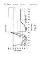
- FIG. 2shows the performance of prior art intumescent mats in a 1000 cycle test at 300° C. with a gap between the fragile structure and the shell of about 4.0 to about 4.1 mm. All mats were preheated at 500° C. for one hour to pre-expand the intumescent material (vermiculite). In the 1000-cycle test, the mat must maintain a pressure of greater than 15 psi at all times to provide adequate holding force on the fragile structure.
- FIG. 2shows a loss in holding force with the eventual failure after about 500 cycles.
- the data presented in this graphcorrelates well with the failures observed with converters mounted with conventional intumescent mounting mats used in TDI diesel applications operating at less than 300° C. The test procedure and specific results of the tests of prior intumescent mats are set forth in detail below.
- Non-intumescent mat systemsare known in the art. Fibers such as SAFFIL® (from ICI, United Kingdom) and MAFTEC® (from Mitsubishi Chemicals, Japan) may be used to mount fragile structures for use over a wide temperature range. These fiber only products contain no intumescent material, such as vermiculite, to increase the holding force as the converter is heated. These mats are composed of polycrystalline fibers with a high Young's Modulus (greater than 20-40 ⁇ 10 6 psi) which function as ceramic springs to provide the required holding force against the fragile structure. These products provide adequate function in turbocharged direct injection (TDI) diesel converters.
- TDIturbocharged direct injection
- European Patent Application EP803643discloses a mat product made with mineral fibers over a very wide composition range (0-99 wt. % Al 2 O 3 , 1-99.8 wt. %SiO 2 ) bonded with a binder to produce a thin, flexible mat for mounting fragile structures.
- the fibersare further defined as preferably having compositions in the range of 95 wt. % Al 2 O 3 , or 75 wt. % Al 2 O 3 —25 wt. % SiO 2 .
- the applicationstates that only fibers with a high elastic modulus will provide sufficient holding force to support the fragile structure as the converter heats and cools during use. Fibers used in prior art intumescent mat products are stated not to be suitable.
- the applicationdescribes the use of conventional organic binders, such as acrylic latex, for applications where the temperature is high enough to burn-out the binder, such as above 500° C.
- conventional organic bindersthermally degrade and become hard. Upon thermal cycling of the converter, the hardened mat is no longer capable of maintaining adequate holding force on the fragile structure and failure results.
- alternative binders which do not hardensuch as a silicone binder, may successfully be used in this temperature range.
- What is needed in the industryis a mat that can function at an average mat temperature range from ambient temperature up to at least about 350° C. and can be installed in exhaust gas treatment devices such as TDI diesel catalytic converters and the like without a loss in holding force.
- the present inventionprovides a non-intumescent mat for providing support for a fragile structure in a low temperature exhaust gas treatment device comprising high temperature resistant, amorphous, inorganic fibers, said fibers having a Young's Modulus of less than about 20 ⁇ 10 6 psi and a geometric mean diameter less than about 5 ⁇ m, said mat optionally including a binder, wherein the mat is adapted to provide a holding force of at least 15 psi throughout an average mat temperature range from ambient temperature up to at least about 350° C.
- the present inventionalso provides an exhaust gas treatment device containing a fragile support structure within a housing, and a support element disposed between the fragile support structure and the housing, wherein said support element comprises a non-intumescent mat comprising high temperature resistant, amorphous, inorganic fibers, said fibers having a Young's Modulus of less than about 20 ⁇ 10 6 psi and a geometric mean diameter less than about 5 ⁇ m, said mat optionally including a binder, and wherein the mat is adapted to provide resistance to slippage of the support element in the housing at a force of at least about 60 times the acceleration of gravity throughout an average mat temperature range from ambient temperature up to at least 350° C.
- a non-intumescent matcomprising high temperature resistant, amorphous, inorganic fibers, said fibers having a Young's Modulus of less than about 20 ⁇ 10 6 psi and a geometric mean diameter less than about 5 ⁇ m, said mat optionally including a binder, and wherein the mat is adapted
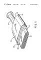
- FIG. 1is a fragmentary, elevational view of a catalytic converter according to the present invention.
- FIG. 2is a graph showing the performance of intumescent mats preheated to 500° C. for one hour in a 1000 cycle test at 300° C. with a gap between the fragile structure and the shell of about 4.0 to about 4.1 mm.
- FIG. 3is a graph of relative expansion of the non-intumescent fiber mats of the present invention at varying temperatures based on different binders for the fiber.
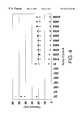
- FIG. 4is a graph showing performance of the non-intumescent fiber mats of the present invention with different binders as compared to a competitive dry layed, needle punched ceramic fiber blanket in a 1000 cycle test at 300° C., with a gap cycling of about 3.0 to about 3.1 mm.
- the present inventionprovides a non-intumescent mat for providing a support structure in a low temperature exhaust gas treatment device.
- the matcomprises high temperature resistant, amorphous, inorganic fibers and optionally includes a binder.
- the fiber of the present inventioncan also be a high temperature resistant fiber.
- high temperature resistantit is meant that the fiber can have a use temperature up to about 1260° C.
- the amorphous inorganic fibers of the present inventionhave a Young's Modulus of less than about 20 ⁇ 10 6 psi and a geometric mean diameter less than about 5 ⁇ m.
- the fiberpreferably comprises one of an amorphous alumina/silica fiber, an alumina/silica/magnesia fiber (such as S-2 Glass from Owens Corning, Toledo, Ohio), mineral wool, E-glass fiber, magnesia-silica fibers (such as ISOFRAXTM fibers from Unifrax Corporation, Niagara Falls, N.Y.), or calcia-magnesia-silica fibers (such as INSULFRAXTM fibers from Unifrax Corporation, Niagara Falls, N.Y. or SUPERWOOLTM fibers from Thermal Ceramics Company).
- an amorphous alumina/silica fibersuch as S-2 Glass from Owens Corning, Toledo, Ohio
- mineral woolsuch as S-2 Glass from Owens Corning, Toledo, Ohio
- E-glass fibersuch as ISOFRAXTM fibers from Unifrax Corporation, Niagara Falls, N.Y.
- magnesia-silica fiberssuch as ISOFRAXTM fibers from Unifrax Corporation, Niagara Falls, N.Y.
- the alumina/silica fibertypically comprises from about 45% to about 60% Al 2 O 3 and about 40% to about 55% SiO 2 ; preferably, the fiber comprises about 50% Al 2 O 3 and about 50% SiO 2 .
- the alumina/silica/magnesia glass fibertypically comprises from about 64% to about 66% SiO 2 , from about 24% to about 25% Al 2 O 3 , and from about 9% to about 10% MgO.
- the E-glass fibertypically comprises from about 52% to about 56% SiO 2 , from about 16% to about 25% CaO, from about 12% to about 16% Al 2 O 3 , from about 5% to about 10% B 2 O 3 , up to about 5% MgO, up to about 2% of sodium oxide and potassium oxide and trace amounts of iron oxide and fluorides, with a typical composition of 55% SiO 2 , 15% Al 2 O 3 , 7% B 2 O 3 , 3% MgO, 19% CaO and traces of the above mentioned materials.
- Magnesia-silica fiberstypically comprise from about 69% to about 86% SiO 2 , from about 14% to about 35% MgO, and from 0% to about 7% ZrO. More information on magnesia-silica fibers can be found in U.S. Pat. No. 5,874,375, which is hereby incorporated by reference. Calcia-magnesia-silica fibers typically comprise about 31% CaO, about 3% MgO, and about 65% SiO 2 .
- the matprovides a holding force of at least 15 psi throughout an average mat temperature range from ambient temperature up to at least about 350° C.
- the average mat temperatureis the arithmetic average temperature across the entire mat.
- the holding forceis provided across the temperature range of the mat as it is heated from ambient temperature up to at least about 350° C.
- An amorphous fiberis defined as a fiber that is melt formed and has not been post processed by heat treating to either anneal or crystallize the fiber, so as to be substantially crystalline free, meaning that no crystallinity is detected by x-ray diffraction.
- the mat of the present inventionincludes a binder.
- Suitable bindersinclude aqueous and non aqueous binders, but preferably the binder utilized is a reactive, thermally setting latex which after cure is a flexible material that is stable up to at least about 350° C.
- Solution strength of the binder in the solvent (if used)can be determined by conventional methods based on the binder loading desired and the workability of the binder system (based on viscosity, solids content, and the like).
- the binderis a silicone latex.
- the fibersare amorphous inorganic or glass fibers that are melt-formed. They are preferably fibers of high chemical purity (greater than about 98%) and preferably have an average diameter in the range of about 1 to about 10 ⁇ m, and most preferably in the range of about 2 to 4 ⁇ m. While not specifically required, the fibers may be beneficiated, as is well known in the art, to obtain a greater than 60 percent fiber index, meaning they contain less than 40 percent shot, and preferably less than about 30 percent shot.
- Catalytic converter 10includes a generally tubular housing 12 formed of two pieces of metal, e.g. high temperature-resistant steel. Housing 12 includes an inlet 14 at one end and an outlet (not shown) at its opposite end. The inlet 14 and outlet are suitably formed at their outer ends whereby they may be secured to conduits in the exhaust system of an internal combustion engine.
- Device 10contains a fragile catalyst support structure, such as a frangible ceramic monolith 18 which is supported and restrained within housing 12 by a support element such as mat 20 , the present invention.
- Monolith 18includes a plurality of gas-pervious passages which extend axially from its inlet end surface at one end to its outlet end surface at its opposite end.
- Monolith 18may be constructed of any suitable refractory metal or ceramic material in any known manner and configuration.
- Monolithsare typically oval or round in cross-sectional configuration, but other shapes are possible.
- the monolithis spaced from its housing by a distance or a gap, which will vary according to the type and design of the device, e.g., a catalytic converter or a diesel particulate trap, utilized.
- This gapis filled by a support element (or mounting mat) 20 to provide resilient support to the ceramic monolith 18 .
- the resilient support element 20provides both thermal insulation to the external environment and mechanical support to the catalyst support structure, protecting the fragile structure from mechanical shock.
- the support element 20also possesses good handleability and is easily processed in the fabrication of devices utilizing its capabilities of maintaining a substantially stable and uniform minimum holding pressure of at least 15 psi after undergoing 1000 mechanical cycles at a nominal temperature of about 350° C.
- cycleit is meant that the gap between the monolith (i.e., fragile structure) and housing is opened and closed over a specific distance and at a predetermined rate.
- the expansion of the gap between a housing and a fragile structure of a given diameteris determined by calculating the coefficient of thermal expansion of the conventional housing at a maximum temperature of 350° C.
- Candidate support matsare characterized for their performance in this test versus installation density.
- a final mat basis weightis then selected which will provide a minimum holding force (Pmin) of greater than about 15 psi after 1000 cycles. The goal is to provide adequate support at the lowest cost, so the minimum basis weight that satisfies the greater than about 15 psi requirement is selected.
- alumina silica fiber mats of the present inventiontypically translates to a minimum basis weight of at least approximately 1200 g/m 2 , and generally approximately 1600 g/m 2 . Higher basis weight mats provide increased holding pressure and thus safety factors; however, at higher cost.
- Mats of the present inventiontypically have a green bulk density of at least about 0.20 g/cm 3 , or greater and have an installed density from about 0.40 to about 0.75 g/cm 3 .
- Mats of the present inventiontypically have a nominal thickness of from about 4.5 to about 13 mm. Nominal thickness is defined as the thickness when measured under a compressive force of 0.7 psi.
- a gap of 3 to 4 mm between the fragile structure and shellis normally sufficient to provide adequate thermal insulation and to minimize the tolerance differences of the fragile structure and shell.
- the weight per unit area (basis weight) of the mat required to fill this gapis bounded on the lower end by the minimum compression force to provide adequate support of the fragile structure against the exhaust gas pressure and axial g-forces to which it is subjected during operation, and on the upper end by the breaking strength of the fragile structure.
- Basis weightranges from about 1000 to about 3000 g/m 2 . For a fragile structure having a 4.66 inch diameter mounted by a tourniquet mounting process, a 3 mm gap is adequate.
- the mat of the present invention having a nominal basis weight of about 1600 g/m 2will result in an installed density of about 0.53 g/cm 3 .
- the matwill have a thickness of approximately 7 mm, which facilitates easy handling and installation during converter assembly, compared to traditional non-intumescent mats.
- the mat of the present inventionprovides resistance to slippage of the support element in the housing at a force of at least about 60 times the acceleration of gravity.
- the resistance to slippageis provided throughout an average mat temperature range from ambient temperature up to at least about 350° C.
- the matprovides sufficient force between the housing and the support element to resist slippage of the support element within the housing, thus avoiding mechanical shock and breakage of the support structure.
- the mounting mat or support element of the present inventioncan be prepared by any known techniques. For instance, using a paper making process, inorganic fibers are mixed with a binder to form a mixture or slurry. Any mixing means may be used, but preferably the fibrous components are mixed at about a 0.25% to 5% consistency or solids content (0.25-5 parts solids to 99.5-95 parts water). The slurry may then be diluted with water to enhance formation, and it may finally be flocculated with flocculating agent and drainage retention aid chemicals. Then, the flocculated mixture or slurry may be placed onto a paper making machine to be formed into a ply of inorganic paper. Alternatively, the plies may be formed by vacuum casting the slurry.
- the inorganic fibersmay be processed into a mat or ply by conventional means such as dry air laying.
- the ply at this stagehas very little structural integrity and is very thick relative to the conventional catalytic converter and diesel trap mounting mats.
- the resultant matcan be dry needled, as is commonly known in the art, to densify the mat and increase its strength.
- the matmay be alternatively processed by the addition of a binder to the mat by impregnation to form a discontinuous fiber composite.
- the binderis added after formation of the mat, rather than forming the mat prepreg as noted hereinabove with respect the conventional paper making technique.
- This method of preparing the mataids in maintaining fiber length by reducing breakage.
- the length of the fibersare about 1 cm to about 10 cm, preferably about 1.25 cm to about 7.75 cm when this method is used.
- continuous filaments of alumina/silica/magnesia glass or E glassare used in the non-intumescent mat of the present invention, they can also be knitted or woven into a fabric.
- Methods of impregnation of the mat with the binderinclude complete submersion of the mat in a liquid binder system, or alternatively spraying the mat.
- a inorganic fiber matwhich can be transported in roll form, is unwound and moved, such as on a conveyer or scrim, past spray nozzles which apply the binder to the mat.
- the matcan be gravity-fed past the spray nozzles.
- the mat/binder prepregis then passed between press rolls which remove excess liquid and densify the prepreg to approximately its desired thickness.
- the densified prepregmay then be passed through an oven to remove any remaining solvent and if necessary to partially cure the binder to form a composite.
- the drying and curing temperatureis primarily dependent upon the binder and solvent (if any) used.
- the compositecan then either be cut or rolled for storage or transportation.
- the mounting matcan also be made in a batch mode, by immersing a section of the mat in a liquid binder, removing the prepreg and pressing to remove excess liquid, thereafter drying to form the composite and storing or cutting to size.
- the compositecan be cut, such as by die stamping, to form mounting mats of exact shapes and sizes with reproducible tolerances.
- This mounting mat 20exhibits suitable handling properties, meaning it can be easily handled and is not so brittle as to crumble in one's hand like mat made with binder. It can be easily and flexibly fitted around the catalyst support structure 18 without cracking and fabricated into the catalytic converter housing 12 to form a resilient support for the catalyst support structure 18 , with minimal or no flashing such as by extrusion or flow of excess material into the flange area 16 and provides a holding pressure against the catalyst support structure 18 of at least 15 psi at a normal temperature of 350° C. after 1000 cycles of gap expansion.
- FIG. 2shows the performance of prior art intumescent mats in a 1000 cycle test at 300° C. with a gap between the fragile structure and the shell of about 4.0 to about 4.1 mm. All mats were preheated at 500° C. for one hour to pre-expand the intumescent material (vermiculite). All mats had an initial installed density of approximately 1.0 g/cm 3 .
- the mat shown by the circle, solid circle at Pmax and open circle at Pmin,is a typical intumescent mat containing approximately 55 wt. % vermiculite, 38 wt. % ceramic fiber, and 7 wt. % organic binder, and is a product called Type-100 that is manufactured by 3M under the trademark INTERAM®.
- the mat shown by the diamond, solid diamond at Pmax and open diamond at Pminis a product called Type-200, also manufactured by 3M under the trademark INTERAM®.
- Type-200is similar to the Type-100, except that the temperature at which expansion of the vermiculite particles begins is claimed to be lower than for the Type-100 mat.
- the mat shown by the square, solid square at Pmax and open square at Pminis a product called AV2 manufactured by Unifrax Corporation under the trademark XPE®, and comprises approximately 45 wt. % vermiculite, 48 wt. % ceramic fiber, and 7% organic binder. The organic binder in all three products is similar.
- the sampleswere compressed to a gap of 4.0 mm between quartz rams mounted in an Instron mechanical properties test machine.
- a furnacewas then installed around the sample/ram assembly. While maintaining the 4.0 mm gap, the furnace was heated to the desired temperature, in this case 500° C., while monitoring the pressure response of the mat. Upon reaching 500° C., the furnace temperature was held constant for 1 hour to remove all of the organic binders and to allow the vermiculite particles to fully expand. After 1 hour, the furnace was cooled to room temperature, while the gap remained at the initial 4.0 mm gap. This preconditioned sample was then re-heated to the desired test temperature, in this case 300° C.
- the furnace temperaturewas held constant and the gap cycled at a speed of approximately 2 mm/minute between 4.0 to 4.1 mm, simulating the expansion of the gap due to shell thermal expansion in a real converter during use.
- the pressure exerted by the matwas monitored as the gap opened and closed.
- Pmaxis the pressure of the mat at 4.0 mm gap
- Pmincorresponds to the pressure of the mat at 4.1 mm. The test was concluded after 1000 cycles.
- FIG. 2shows that the Type-100 and Type-200 mats failed to meet the Pmin>15 psi requirement even on the first cycle. Only the AV2 mat, square symbol, was able to maintain holding force above the minimum 15 psi. Even this mat had a holding force less than 15 psi after pre-heating, which could lead to a failure condition.
- Simulation of a TDI diesel converterwas performed by cycle testing mats at 300° C. for 1000 cycles between a gap of about 3.0 to about 3.1 mm. The results are shown in FIG. 4 .
- the sampleswere a 1550 g/m 2 of a competitive dry layed, needle punched ceramic (about 50% alumina/50% silica) fiber blanket, such as ULTRAFELT® manufactured by Thermal Ceramics, Augusta, Ga., (shown by an open diamond), and a 1600 g/m 2 mat of the present invention prepared with a 50% alumina/50% silica fiber with no binder (shown by a triangle); a silicone binder (shown by a solid square); and an acrylic binder that was not burned out prior to installation (shown by an solid circle).
- a competitive dry layed, needle punched ceramic (about 50% alumina/50% silica) fiber blanketsuch as ULTRAFELT® manufactured by Thermal Ceramics, Augusta, Ga., (shown by an open diamond)
- the mat with the silicone bindercomprised 92% of an amorphous fiber comprising 50% Al 2 O 3 and about 50% SiO 2 with a fiber index of 72% and 8% of a silicone latex binder (DOW CORNING #85 silicone latex from Dow Corning, Inc. Midland, Mich.).
- the resulting mathad a basis weight of 1600 g/m 2 and was 7 mm thick.
- the ULTRAFELT® and the silicone latex binder matsmaintained a holding force greater than 15 psi.
- the mat with the acrylic binderwas similar to the mat with the silicone binder, with the 8% silicone binder being replaced with 8% HYCAR® 26083 acrylic latex, available from B.F. Goodrich, Brecksville, Ohio. Again, the sample had a basis weight of 1600 g/m 2 and was about 7 mm thick. The binder was not preburned, and thus failed on the first cycle. A second sample was prepared and was pre-burned prior to testing. This second mat performed comparably to the mat with the silicone binder.
- a 4.66′′ diameter converterwas assembled with comparative mats and tested in a hot shake test at 300° C. with an acceleration of 60 times gravity (60 g's).
- the converter with a traditional intumescent matconsisting of approximately 55% unexpanded vermiculite, 37% ceramic fiber, and 8% acrylic latex binder, such as INTERAM® TYPE-100 and INTERAM® TYPE-200, lost its holding force and the fragile structure slipped within the shell in less than 50 hours.
- a mat of the present inventionmade with amorphous alumina/silica fiber and an acrylic latex binder which had been burned out prior to installation in the converter, was run in the hot shake test at 300° C. with an acceleration of 60 g and performed for 100 hours without failure. Upon inspection after testing, the fragile structure was found to be firmly mounted in the shell, with no relative axial movement. The mat was also found to be undamaged by gas erosion or other visible degradation.
- a mat of the present inventionmade with a silicone latex binder, was run in the hot shake test at 300° C. with an acceleration of 60 g and performed for 100 hours without failure.
- the present inventionachieves the objects of the invention.
- the present inventiontherefore provides a non-intumescent mat comprising an amorphous, inorganic fiber that functions up to about 350° C. without a loss in holding force in catalytic converters and the like.
Landscapes
- Engineering & Computer Science (AREA)
- Chemical & Material Sciences (AREA)
- Environmental & Geological Engineering (AREA)
- Health & Medical Sciences (AREA)
- Biomedical Technology (AREA)
- Analytical Chemistry (AREA)
- General Chemical & Material Sciences (AREA)
- Oil, Petroleum & Natural Gas (AREA)
- Chemical Kinetics & Catalysis (AREA)
- Textile Engineering (AREA)
- Inorganic Chemistry (AREA)
- Combustion & Propulsion (AREA)
- Mechanical Engineering (AREA)
- Exhaust Gas After Treatment (AREA)
- Laminated Bodies (AREA)
- Chemical Or Physical Treatment Of Fibers (AREA)
- Filtering Materials (AREA)
- Nonwoven Fabrics (AREA)
- Inorganic Fibers (AREA)
- Glass Compositions (AREA)
- Respiratory Apparatuses And Protective Means (AREA)
Abstract
Description
Claims (36)
Priority Applications (2)
| Application Number | Priority Date | Filing Date | Title |
|---|---|---|---|
| US09/456,937US6231818B1 (en) | 1998-12-08 | 1999-12-07 | Amorphous non-intumescent inorganic fiber mat for low temperature exhaust gas treatment devices |
| US09/854,836US6855298B2 (en) | 1998-12-08 | 2001-05-14 | Amorphous non-intumescent inorganic fiber mat for low temperature exhaust gas treatment device |
Applications Claiming Priority (2)
| Application Number | Priority Date | Filing Date | Title |
|---|---|---|---|
| US11135398P | 1998-12-08 | 1998-12-08 | |
| US09/456,937US6231818B1 (en) | 1998-12-08 | 1999-12-07 | Amorphous non-intumescent inorganic fiber mat for low temperature exhaust gas treatment devices |
Related Child Applications (1)
| Application Number | Title | Priority Date | Filing Date |
|---|---|---|---|
| US09/854,836ContinuationUS6855298B2 (en) | 1998-12-08 | 2001-05-14 | Amorphous non-intumescent inorganic fiber mat for low temperature exhaust gas treatment device |
Publications (1)
| Publication Number | Publication Date |
|---|---|
| US6231818B1true US6231818B1 (en) | 2001-05-15 |
Family
ID=22338031
Family Applications (2)
| Application Number | Title | Priority Date | Filing Date |
|---|---|---|---|
| US09/456,937Expired - Fee RelatedUS6231818B1 (en) | 1998-12-08 | 1999-12-07 | Amorphous non-intumescent inorganic fiber mat for low temperature exhaust gas treatment devices |
| US09/854,836Expired - Fee RelatedUS6855298B2 (en) | 1998-12-08 | 2001-05-14 | Amorphous non-intumescent inorganic fiber mat for low temperature exhaust gas treatment device |
Family Applications After (1)
| Application Number | Title | Priority Date | Filing Date |
|---|---|---|---|
| US09/854,836Expired - Fee RelatedUS6855298B2 (en) | 1998-12-08 | 2001-05-14 | Amorphous non-intumescent inorganic fiber mat for low temperature exhaust gas treatment device |
Country Status (15)
| Country | Link |
|---|---|
| US (2) | US6231818B1 (en) |
| EP (1) | EP1165209B1 (en) |
| JP (1) | JP4526187B2 (en) |
| KR (1) | KR100593226B1 (en) |
| CN (1) | CN1131093C (en) |
| AT (1) | ATE289859T1 (en) |
| BR (1) | BR9915039B1 (en) |
| CA (1) | CA2353566C (en) |
| DE (2) | DE1165209T1 (en) |
| ES (1) | ES2237962T3 (en) |
| HK (1) | HK1041841A1 (en) |
| HU (1) | HUP0104490A3 (en) |
| MX (1) | MXPA01005803A (en) |
| WO (1) | WO2000033946A1 (en) |
| ZA (1) | ZA200003280B (en) |
Cited By (47)
| Publication number | Priority date | Publication date | Assignee | Title |
|---|---|---|---|---|
| US20030091479A1 (en)* | 2001-11-09 | 2003-05-15 | Zlatomir Kircanski | High temperature resistant material |
| US20030104189A1 (en)* | 2000-06-21 | 2003-06-05 | Masanao Agata | Holding/sealing material for use in catalytic converter for clarifying gaseous emission |
| WO2004011785A1 (en)* | 2002-07-31 | 2004-02-05 | 3M Innovative Properties Company | Mat for mounting a pollution control element in a pollution control device for the treatment of exhaust gas |
| US20040022699A1 (en)* | 2000-11-10 | 2004-02-05 | Koji Fukushima | Catalytic converter and method for manufacture thereof |
| WO2004031544A2 (en) | 2002-09-30 | 2004-04-15 | Unifrax Corporation | Exhaust gas treatment device and method for making the same |
| US20040081595A1 (en)* | 2002-10-29 | 2004-04-29 | Turek Alan G. | Exhaust emission control devices and method of making the same |
| EP1486648A1 (en)* | 2003-06-10 | 2004-12-15 | 3M Innovative Properties Company | Mounting mat for a catalytic converter |
| US20050207947A1 (en)* | 2004-03-18 | 2005-09-22 | Ford Global Technologies, Llc | Fiber and corrugated metal mat support |
| US20060008395A1 (en)* | 2004-06-29 | 2006-01-12 | Unifrax Corporation | Exhaust gas treatment device and method for making the same |
| US20060153746A1 (en)* | 2002-07-31 | 2006-07-13 | Merry Richard P | Mat for mounting a pollution control element in a pollution control device for the treatment of exhaust gas |
| US20060242951A1 (en)* | 2005-04-29 | 2006-11-02 | Caterpillar Inc. | Refractory material retention device |
| US20060257298A1 (en)* | 2003-06-10 | 2006-11-16 | Merry Richard P | Mounting mat for a catalytic converter |
| US20060286014A1 (en)* | 2003-01-31 | 2006-12-21 | Peisert Joseph C | System for securing the end cone or mounting mat of a pollution control device |
| US20070065349A1 (en)* | 2003-04-02 | 2007-03-22 | 3M Innovative Properties Company | Non-classified end cone insulation for catalytic converter |
| US20070178024A1 (en)* | 2003-09-26 | 2007-08-02 | Faurecia Systemes D'echappement | Exhaust Line And Power Train Comprising Same |
| US20070212272A1 (en)* | 2006-03-10 | 2007-09-13 | Ibiden Co., Ltd. | Holding sealer and exhaust gas purifying device |
| US20070292318A1 (en)* | 2006-06-16 | 2007-12-20 | Ibiden Co., Ltd. | Holding sealer, exhaust gas processing device and manufacturing method of the same |
| WO2008121801A1 (en)* | 2007-03-30 | 2008-10-09 | 3M Innovative Properties Company | Fiber mat containing an organosilicon compound and pollution control device using it |
| US20090060800A1 (en)* | 2007-08-31 | 2009-03-05 | Unifrax I Llc | Substrate Mounting System |
| US20090060802A1 (en)* | 2007-08-31 | 2009-03-05 | Unifrax I Llc | Exhaust gas treatment device |
| US20090130937A1 (en)* | 2005-11-10 | 2009-05-21 | The Morgan Crucible Company Plc | High Temperature Resistant Fibres |
| US20090155539A1 (en)* | 2007-12-14 | 2009-06-18 | Douglas Bracher | System, apparatus and method for manufacturing metal ingots |
| US20090208732A1 (en)* | 2005-12-14 | 2009-08-20 | Claus Middendorf | Mounting mat for a pollution control device |
| US20100055004A1 (en)* | 2008-08-29 | 2010-03-04 | Unifrax I Llc | Mounting mat with flexible edge protection and exhaust gas treatment device incorporating the mounting mat |
| US20100115900A1 (en)* | 2007-02-19 | 2010-05-13 | De Rovere Anne N | Flexible fibrous material, pollution control device, and methods of making the same |
| US20100173552A1 (en)* | 2009-01-05 | 2010-07-08 | Unifrax I Llc | High strength biosoluble inorganic fiber insulation mat |
| EP2226425A1 (en)* | 2009-01-26 | 2010-09-08 | Ibiden Co., Ltd. | Mat material, exhaust gas treating apparatus, and method of manufacturing mat material |
| US20100266462A1 (en)* | 2009-04-17 | 2010-10-21 | Amit Kumar | Exhaust Gas Treatment Device |
| US20110023430A1 (en)* | 2007-08-31 | 2011-02-03 | Amit Kumar | Multiple Layer Substrate Support and Exhaust Gas Treatment Device |
| US20110033343A1 (en)* | 2009-08-10 | 2011-02-10 | Fernandes Jr Sergio David | Variable basis weight mounting mat or pre-form and exhaust gas treatment device |
| US20110094419A1 (en)* | 2008-12-15 | 2011-04-28 | Fernando Joseph A | Ceramic Honeycomb Structure Skin Coating |
| US20110097246A1 (en)* | 2009-09-23 | 2011-04-28 | Unifrax I Llc | Low Shear Mounting Mat for Pollution Control Devices |
| US20110123801A1 (en)* | 2009-11-24 | 2011-05-26 | Valenciano Philip F | Intumescent rod |
| US20110126499A1 (en)* | 2009-09-24 | 2011-06-02 | Amit Kumar | Multiple Layer Mat and Exhaust Gas Treatment Device |
| US20110150715A1 (en)* | 2009-12-17 | 2011-06-23 | Unifrax I Llc | Multilayer Mounting Mat for Pollution Control Devices |
| US20110150717A1 (en)* | 2009-12-17 | 2011-06-23 | Unifrax I Llc | Mounting mat for exhaust gas treatment device |
| US8349265B2 (en) | 2010-08-13 | 2013-01-08 | Unifrax I Llc | Mounting mat with flexible edge protection and exhaust gas treatment device incorporating the mounting mat |
| US8578672B2 (en) | 2010-08-02 | 2013-11-12 | Tremco Incorporated | Intumescent backer rod |
| US8765069B2 (en) | 2010-08-12 | 2014-07-01 | Unifrax I Llc | Exhaust gas treatment device |
| US8926911B2 (en) | 2009-12-17 | 2015-01-06 | Unifax I LLC | Use of microspheres in an exhaust gas treatment device mounting mat |
| US9120703B2 (en) | 2010-11-11 | 2015-09-01 | Unifrax I Llc | Mounting mat and exhaust gas treatment device |
| US9174169B2 (en) | 2009-08-14 | 2015-11-03 | Unifrax I Llc | Mounting mat for exhaust gas treatment device |
| US9452719B2 (en) | 2015-02-24 | 2016-09-27 | Unifrax I Llc | High temperature resistant insulation mat |
| US9631529B2 (en) | 2009-04-21 | 2017-04-25 | Saffil Automotive Limited | Erosion resistant mounting mats |
| US9796634B2 (en) | 2012-01-23 | 2017-10-24 | Nichias Corporation | Holding material for gas treatment device, gas treatment device, and production processes therefor |
| US20190161029A1 (en)* | 2017-11-24 | 2019-05-30 | Futaba Industrial Co., Ltd. | Method of manufacturing insulator |
| US20200165758A1 (en)* | 2017-07-18 | 2020-05-28 | Thermal Ceramics Uk Limited | Melt-Formed Inorganic Fibres |
Families Citing this family (33)
| Publication number | Priority date | Publication date | Assignee | Title |
|---|---|---|---|---|
| JP2002302875A (en)* | 2001-04-02 | 2002-10-18 | Mitsubishi Chemicals Corp | Heat resistant mat, method for producing the same, and catalytic converter for purifying exhaust gas |
| JP4761655B2 (en)* | 2001-06-22 | 2011-08-31 | スリーエム イノベイティブ プロパティズ カンパニー | Catalyst carrier holding material and catalytic converter |
| US7261864B2 (en) | 2001-06-22 | 2007-08-28 | 3M Innovative Properties Company | Catalyst carrier holding material and catalytic converter |
| WO2003031368A2 (en)* | 2001-10-09 | 2003-04-17 | 3M Innovative Properties Company | Compositions containing biosoluble inorganic fibers and micaceous binders |
| JP4278998B2 (en)* | 2002-02-18 | 2009-06-17 | アイシン高丘株式会社 | Method for manufacturing converter case |
| GB0229380D0 (en)* | 2002-12-17 | 2003-01-22 | Saffil Ltd | Mats |
| US7152633B2 (en)* | 2003-09-17 | 2006-12-26 | Thermo-Tec | Heat shield |
| JP4665618B2 (en)* | 2005-06-10 | 2011-04-06 | イビデン株式会社 | Manufacturing method of holding sealing material |
| WO2007005836A2 (en)* | 2005-06-30 | 2007-01-11 | Unifrax Corporation | Phosphate coated inorganic fiber and methods of preparation and use |
| KR101497865B1 (en)* | 2005-09-08 | 2015-03-04 | 쓰리엠 이노베이티브 프로퍼티즈 컴파니 | Holding material for pollution control element and pollution control apparatus |
| JP2007177767A (en) | 2005-12-28 | 2007-07-12 | Ibiden Co Ltd | Hold-sealing material for exhaust gas-treating body, exhaust gas-treating device and method for manufacturing hold-sealing material |
| JP4959206B2 (en)* | 2006-03-02 | 2012-06-20 | イビデン株式会社 | Heat-resistant sheet and exhaust gas purification device |
| WO2008005008A2 (en)* | 2006-06-30 | 2008-01-10 | Unifrax Corporation | Inorganic fiber |
| KR101228243B1 (en)* | 2007-01-05 | 2013-01-31 | (주)엘지하우시스 | A non-intumescent mat comprising crystalline type inorganic fiber and a method for manufacturing the same |
| CN102203393B (en)* | 2008-08-27 | 2016-01-20 | 维达控股股份有限公司 | catalytic converter unit |
| US8827883B2 (en) | 2008-11-06 | 2014-09-09 | Nichias Corporation | Base material for disk, process for producing the same, and disk roll |
| JP5386150B2 (en)* | 2008-11-06 | 2014-01-15 | ニチアス株式会社 | Base material for disk material, method for manufacturing the same, and disk roll |
| SG177442A1 (en) | 2009-07-02 | 2012-02-28 | Du Pont | Semiconductor manufacture component |
| US8012577B2 (en)* | 2009-07-02 | 2011-09-06 | E.I. Du Pont De Nemours And Company | Composite article made by a process |
| US8480916B2 (en)* | 2009-10-02 | 2013-07-09 | Unifrax I Llc | Ultra low weight insulation board |
| WO2012067156A1 (en) | 2010-11-18 | 2012-05-24 | 日本碍子株式会社 | Heat conduction member |
| CN105358499A (en) | 2013-03-15 | 2016-02-24 | 尤尼弗瑞克斯I有限责任公司 | Inorganic fiber |
| CA2955350C (en) | 2014-07-16 | 2022-10-25 | Unifrax I Llc | Inorganic fiber with improved shrinkage and strength |
| US10023491B2 (en) | 2014-07-16 | 2018-07-17 | Unifrax I Llc | Inorganic fiber |
| MX387962B (en) | 2014-07-17 | 2025-03-19 | Unifrax I Llc | INORGANIC FIBER WITH IMPROVED CONTRACTION AND STRENGTH. |
| US10598068B2 (en) | 2015-12-21 | 2020-03-24 | Emissol, Llc | Catalytic converters having non-linear flow channels |
| US9919957B2 (en) | 2016-01-19 | 2018-03-20 | Unifrax I Llc | Inorganic fiber |
| AU2017243978A1 (en)* | 2016-03-31 | 2018-09-20 | Grillex Pty Ltd | Cooking apparatus and method of assembly |
| US11203551B2 (en) | 2017-10-10 | 2021-12-21 | Unifrax I Llc | Low biopersistence inorganic fiber free of crystalline silica |
| US10882779B2 (en) | 2018-05-25 | 2021-01-05 | Unifrax I Llc | Inorganic fiber |
| EP4031504A4 (en)* | 2020-12-11 | 2023-12-06 | Unifrax I LLC | Low bio-persistent high temperature resistant inorganic fibers |
| CN114165318B (en)* | 2021-12-09 | 2023-07-25 | 天津大学合肥创新发展研究院 | Integrated device inner core for recovering and post-treating waste heat of tail gas of internal combustion engine |
| CN114656193A (en)* | 2022-04-29 | 2022-06-24 | 乐清市华日耐火器材有限公司 | Non-expansion type gasket for GBD (GBD) packaging and preparation method thereof |
Citations (12)
| Publication number | Priority date | Publication date | Assignee | Title |
|---|---|---|---|---|
| GB1481133A (en) | 1974-05-30 | 1977-07-27 | Babcock & Wilcox Co | Ceramic refractory fibrous material |
| US4279864A (en) | 1978-12-04 | 1981-07-21 | Nippon Soken, Inc. | Monolithic catalyst converter |
| US4929429A (en) | 1988-02-11 | 1990-05-29 | Minnesota Mining And Manufacturing Company | Catalytic converter |
| US5028397A (en) | 1988-02-11 | 1991-07-02 | Minnesota Mining And Manufacturing Company | Catalytic converter |
| US5132061A (en)* | 1987-09-03 | 1992-07-21 | Armstrong World Industries, Inc. | Preparing gasket compositions having expanded microspheres |
| US5250269A (en) | 1992-05-21 | 1993-10-05 | Minnesota Mining And Manufacturing Company | Catalytic converter having a metallic monolith mounted by a heat-insulating mat of refractory ceramic fibers |
| US5290522A (en) | 1993-01-07 | 1994-03-01 | Minnesota Mining And Manufacturing Company | Catalytic converter mounting mat |
| US5389716A (en)* | 1992-06-26 | 1995-02-14 | Georgia-Pacific Resins, Inc. | Fire resistant cured binder for fibrous mats |
| US5580532A (en) | 1993-04-22 | 1996-12-03 | Unifrax Corporation | Mounting mat for fragile structures such as catalytic converters |
| US5585312A (en)* | 1994-08-23 | 1996-12-17 | Unifrax Corporation | High temperature stable continuous filament glass ceramic fiber |
| EP0765993A1 (en) | 1995-04-13 | 1997-04-02 | Mitsubishi Chemical Industries Limited | Monolith holding material, method for producing the same, catalytic converter using the monolith, and method for producing the same |
| EP0803643A1 (en) | 1996-04-27 | 1997-10-29 | LEISTRITZ AG & CO. Abgastechnik | Exhaust gas catalyst |
Family Cites Families (8)
| Publication number | Priority date | Publication date | Assignee | Title |
|---|---|---|---|---|
| US3458329A (en)* | 1963-02-13 | 1969-07-29 | Minnesota Mining & Mfg | Ceramic greensheets |
| US4863700A (en)* | 1985-04-16 | 1989-09-05 | Stemcor | Monolithic catalytic converter mounting arrangement |
| US5032441A (en)* | 1989-05-01 | 1991-07-16 | The Carborundum Company | Intumescent conforming mounting pad |
| US4999168A (en)* | 1989-05-01 | 1991-03-12 | The Carborundum Company | Crack resistant intumescent sheet material |
| JP3282362B2 (en)* | 1994-04-15 | 2002-05-13 | 三菱化学株式会社 | Grasping material for exhaust gas purification equipment |
| JP3025433B2 (en)* | 1995-04-13 | 2000-03-27 | 三菱化学株式会社 | Monolith holding material, method for producing the same, and catalytic converter using the monolith |
| US5736109A (en)* | 1995-06-30 | 1998-04-07 | Minnesota Mining And Manufacturing Company | Intumescent sheet material and paste with organic binder |
| WO1999046028A1 (en)* | 1998-03-11 | 1999-09-16 | Unifrax Corporation | Support element for fragile structures such as catalytic converters |
- 1999
- 1999-12-07MXMXPA01005803Apatent/MXPA01005803A/ennot_activeIP Right Cessation
- 1999-12-07EPEP99966008Apatent/EP1165209B1/ennot_activeExpired - Lifetime
- 1999-12-07ATAT99966008Tpatent/ATE289859T1/ennot_activeIP Right Cessation
- 1999-12-07HKHK02103705.8Apatent/HK1041841A1/enunknown
- 1999-12-07DEDE1165209Tpatent/DE1165209T1/enactivePending
- 1999-12-07BRBRPI9915039-5Apatent/BR9915039B1/ennot_activeIP Right Cessation
- 1999-12-07CACA002353566Apatent/CA2353566C/ennot_activeExpired - Fee Related
- 1999-12-07USUS09/456,937patent/US6231818B1/ennot_activeExpired - Fee Related
- 1999-12-07WOPCT/US1999/028796patent/WO2000033946A1/enactiveIP Right Grant
- 1999-12-07HUHU0104490Apatent/HUP0104490A3/enunknown
- 1999-12-07JPJP2000586433Apatent/JP4526187B2/ennot_activeExpired - Fee Related
- 1999-12-07DEDE69924032Tpatent/DE69924032T2/ennot_activeExpired - Fee Related
- 1999-12-07CNCN99814096Apatent/CN1131093C/ennot_activeExpired - Fee Related
- 1999-12-07ESES99966008Tpatent/ES2237962T3/ennot_activeExpired - Lifetime
- 1999-12-07KRKR1020017005834Apatent/KR100593226B1/ennot_activeExpired - Fee Related
- 2000
- 2000-06-29ZAZA200003280Apatent/ZA200003280B/enunknown
- 2001
- 2001-05-14USUS09/854,836patent/US6855298B2/ennot_activeExpired - Fee Related
Patent Citations (12)
| Publication number | Priority date | Publication date | Assignee | Title |
|---|---|---|---|---|
| GB1481133A (en) | 1974-05-30 | 1977-07-27 | Babcock & Wilcox Co | Ceramic refractory fibrous material |
| US4279864A (en) | 1978-12-04 | 1981-07-21 | Nippon Soken, Inc. | Monolithic catalyst converter |
| US5132061A (en)* | 1987-09-03 | 1992-07-21 | Armstrong World Industries, Inc. | Preparing gasket compositions having expanded microspheres |
| US4929429A (en) | 1988-02-11 | 1990-05-29 | Minnesota Mining And Manufacturing Company | Catalytic converter |
| US5028397A (en) | 1988-02-11 | 1991-07-02 | Minnesota Mining And Manufacturing Company | Catalytic converter |
| US5250269A (en) | 1992-05-21 | 1993-10-05 | Minnesota Mining And Manufacturing Company | Catalytic converter having a metallic monolith mounted by a heat-insulating mat of refractory ceramic fibers |
| US5389716A (en)* | 1992-06-26 | 1995-02-14 | Georgia-Pacific Resins, Inc. | Fire resistant cured binder for fibrous mats |
| US5290522A (en) | 1993-01-07 | 1994-03-01 | Minnesota Mining And Manufacturing Company | Catalytic converter mounting mat |
| US5580532A (en) | 1993-04-22 | 1996-12-03 | Unifrax Corporation | Mounting mat for fragile structures such as catalytic converters |
| US5585312A (en)* | 1994-08-23 | 1996-12-17 | Unifrax Corporation | High temperature stable continuous filament glass ceramic fiber |
| EP0765993A1 (en) | 1995-04-13 | 1997-04-02 | Mitsubishi Chemical Industries Limited | Monolith holding material, method for producing the same, catalytic converter using the monolith, and method for producing the same |
| EP0803643A1 (en) | 1996-04-27 | 1997-10-29 | LEISTRITZ AG & CO. Abgastechnik | Exhaust gas catalyst |
Cited By (94)
| Publication number | Priority date | Publication date | Assignee | Title |
|---|---|---|---|---|
| US20030104189A1 (en)* | 2000-06-21 | 2003-06-05 | Masanao Agata | Holding/sealing material for use in catalytic converter for clarifying gaseous emission |
| US6960386B2 (en)* | 2000-06-21 | 2005-11-01 | Ibiden Co., Ltd. | Holding/sealing material for use in catalytic converter for clarifying gaseous emission |
| US7575727B2 (en)* | 2000-11-10 | 2009-08-18 | Ibiden Co., Ltd. | Catalytic converter and method for manufacturing the same |
| US20040022699A1 (en)* | 2000-11-10 | 2004-02-05 | Koji Fukushima | Catalytic converter and method for manufacture thereof |
| US20030091479A1 (en)* | 2001-11-09 | 2003-05-15 | Zlatomir Kircanski | High temperature resistant material |
| CN1678821B (en)* | 2002-07-31 | 2011-06-08 | 3M创新有限公司 | Mat for mounting a pollution control element in a pollution control device for the treatment of exhaust gas |
| EP1388649A1 (en)* | 2002-07-31 | 2004-02-11 | 3M Innovative Properties Company | Mat for mounting a pollution control monolith in a pollution control device for the treatment of exhaust gas of a diesel engine powered machine |
| US7704459B2 (en) | 2002-07-31 | 2010-04-27 | 3M Innovative Properties Company | Mat for mounting a pollution control element in a pollution control device for the treatment of exhaust gas |
| US20060153746A1 (en)* | 2002-07-31 | 2006-07-13 | Merry Richard P | Mat for mounting a pollution control element in a pollution control device for the treatment of exhaust gas |
| WO2004011785A1 (en)* | 2002-07-31 | 2004-02-05 | 3M Innovative Properties Company | Mat for mounting a pollution control element in a pollution control device for the treatment of exhaust gas |
| US20040134172A1 (en)* | 2002-09-30 | 2004-07-15 | Unifrax Corporation | Exhaust gas treatment device and method for making the same |
| WO2004031544A2 (en) | 2002-09-30 | 2004-04-15 | Unifrax Corporation | Exhaust gas treatment device and method for making the same |
| US7033412B2 (en) | 2002-09-30 | 2006-04-25 | Unifrax Corporation | Exhaust gas treatment device and method for making the same |
| US20040081595A1 (en)* | 2002-10-29 | 2004-04-29 | Turek Alan G. | Exhaust emission control devices and method of making the same |
| US20060286014A1 (en)* | 2003-01-31 | 2006-12-21 | Peisert Joseph C | System for securing the end cone or mounting mat of a pollution control device |
| US7820117B2 (en) | 2003-01-31 | 2010-10-26 | 3M Innovative Properties Company | System for securing the end cone or mounting mat of a pollution control device |
| US8186058B2 (en)* | 2003-04-02 | 2012-05-29 | 3M Innovative Properties Company | Exhaust system component having insulated double wall |
| US20070065349A1 (en)* | 2003-04-02 | 2007-03-22 | 3M Innovative Properties Company | Non-classified end cone insulation for catalytic converter |
| US7854904B2 (en) | 2003-06-10 | 2010-12-21 | 3M Innovative Properties Company | Mounting mat for a catalytic converter |
| US20060257298A1 (en)* | 2003-06-10 | 2006-11-16 | Merry Richard P | Mounting mat for a catalytic converter |
| WO2005003530A1 (en)* | 2003-06-10 | 2005-01-13 | 3M Innovative Properties Company | Mounting mat for a catalytic converter |
| CN1806101B (en)* | 2003-06-10 | 2012-03-21 | 3M创新有限公司 | Mounting mat for a catalytic converter |
| EP1486648A1 (en)* | 2003-06-10 | 2004-12-15 | 3M Innovative Properties Company | Mounting mat for a catalytic converter |
| US20070178024A1 (en)* | 2003-09-26 | 2007-08-02 | Faurecia Systemes D'echappement | Exhaust Line And Power Train Comprising Same |
| US20050207947A1 (en)* | 2004-03-18 | 2005-09-22 | Ford Global Technologies, Llc | Fiber and corrugated metal mat support |
| US7316803B2 (en) | 2004-03-18 | 2008-01-08 | Ford Global Technologies, Llc | Fiber and corrugated metal mat support |
| US20110123417A1 (en)* | 2004-06-29 | 2011-05-26 | Ten Eyck John D | Exhaust gas treatment device |
| US8182752B2 (en) | 2004-06-29 | 2012-05-22 | Unifrax I Llc | Exhaust gas treatment device |
| US20060008395A1 (en)* | 2004-06-29 | 2006-01-12 | Unifrax Corporation | Exhaust gas treatment device and method for making the same |
| WO2006004974A3 (en)* | 2004-06-29 | 2006-03-09 | Unifrax Corp | Exhaust gas treatment device and method for making the same |
| RU2388522C2 (en)* | 2004-06-29 | 2010-05-10 | Юнифрэкс Корпорейшн | Device to process exhaust gases and method of its fabrication |
| US7971357B2 (en) | 2004-06-29 | 2011-07-05 | Unifrax I Llc | Exhaust gas treatment device and method for making the same |
| US7998422B2 (en) | 2004-06-29 | 2011-08-16 | Unifrax I Llc | Exhaust gas treatment device |
| US20060242951A1 (en)* | 2005-04-29 | 2006-11-02 | Caterpillar Inc. | Refractory material retention device |
| US20090130937A1 (en)* | 2005-11-10 | 2009-05-21 | The Morgan Crucible Company Plc | High Temperature Resistant Fibres |
| US8163377B2 (en) | 2005-11-10 | 2012-04-24 | The Morgan Crucible Company Plc | High temperature resistant fibres |
| US11293125B2 (en) | 2005-12-14 | 2022-04-05 | 3M Innovative Properties Company | Mat having long and short inorganic fibers |
| US10662560B2 (en) | 2005-12-14 | 2020-05-26 | 3M Innovative Properties Company | Mounting mat for a pollution control device |
| US9765458B2 (en) | 2005-12-14 | 2017-09-19 | 3M Innovative Properties Company | Mounting mat for a pollution control device |
| US20090208732A1 (en)* | 2005-12-14 | 2009-08-20 | Claus Middendorf | Mounting mat for a pollution control device |
| US20110200490A1 (en)* | 2006-03-10 | 2011-08-18 | Ibiden Co., Ltd. | Holding sealer and exhaust gas purifying device |
| US7950148B2 (en)* | 2006-03-10 | 2011-05-31 | Ibiden Co., Ltd. | Holding sealer and exhaust gas purifying device |
| US20070212272A1 (en)* | 2006-03-10 | 2007-09-13 | Ibiden Co., Ltd. | Holding sealer and exhaust gas purifying device |
| US7842117B2 (en)* | 2006-06-16 | 2010-11-30 | Ibiden Co., Ltd. | Holding sealer, exhaust gas processing device and manufacturing method of the same |
| US20070292318A1 (en)* | 2006-06-16 | 2007-12-20 | Ibiden Co., Ltd. | Holding sealer, exhaust gas processing device and manufacturing method of the same |
| US20100115900A1 (en)* | 2007-02-19 | 2010-05-13 | De Rovere Anne N | Flexible fibrous material, pollution control device, and methods of making the same |
| US8226897B2 (en) | 2007-03-30 | 2012-07-24 | 3M Innovative Properties Company | Fiber mat containing an organosilicon compound and pollution control device using it |
| US20100150791A1 (en)* | 2007-03-30 | 2010-06-17 | Kunze Ulrich E | Fiber mat containing an organosilicon compound and pollution control device using it |
| US8916103B2 (en) | 2007-03-30 | 2014-12-23 | 3M Innovative Properties Company | Fiber mat containing an organosilicon compound and pollution control device using it |
| WO2008121801A1 (en)* | 2007-03-30 | 2008-10-09 | 3M Innovative Properties Company | Fiber mat containing an organosilicon compound and pollution control device using it |
| US8007732B2 (en)* | 2007-08-31 | 2011-08-30 | Unifrax 1 Llc | Exhaust gas treatment device |
| US20090060800A1 (en)* | 2007-08-31 | 2009-03-05 | Unifrax I Llc | Substrate Mounting System |
| US8017085B2 (en) | 2007-08-31 | 2011-09-13 | Unifrax I Llc | Substrate mounting system |
| US20090060802A1 (en)* | 2007-08-31 | 2009-03-05 | Unifrax I Llc | Exhaust gas treatment device |
| US20110023430A1 (en)* | 2007-08-31 | 2011-02-03 | Amit Kumar | Multiple Layer Substrate Support and Exhaust Gas Treatment Device |
| US8524161B2 (en) | 2007-08-31 | 2013-09-03 | Unifrax I Llc | Multiple layer substrate support and exhaust gas treatment device |
| US8517083B2 (en) | 2007-12-14 | 2013-08-27 | Refractory Specialties, Incorporated | System, apparatus and method for manufacturing metal ingots |
| US20090155539A1 (en)* | 2007-12-14 | 2009-06-18 | Douglas Bracher | System, apparatus and method for manufacturing metal ingots |
| US20100055004A1 (en)* | 2008-08-29 | 2010-03-04 | Unifrax I Llc | Mounting mat with flexible edge protection and exhaust gas treatment device incorporating the mounting mat |
| US8211373B2 (en) | 2008-08-29 | 2012-07-03 | Unifrax I Llc | Mounting mat with flexible edge protection and exhaust gas treatment device incorporating the mounting mat |
| US8263512B2 (en) | 2008-12-15 | 2012-09-11 | Unifrax I Llc | Ceramic honeycomb structure skin coating |
| US8696807B2 (en) | 2008-12-15 | 2014-04-15 | Unifrax I Llc | Ceramic honeycomb structure skin coating |
| US8679615B2 (en) | 2008-12-15 | 2014-03-25 | Unifrax I Llc | Ceramic honeycomb structure skin coating |
| US20110094419A1 (en)* | 2008-12-15 | 2011-04-28 | Fernando Joseph A | Ceramic Honeycomb Structure Skin Coating |
| US9163148B2 (en) | 2008-12-15 | 2015-10-20 | Unifrax I Llc | Ceramic honeycomb structure skin coating |
| US20100173552A1 (en)* | 2009-01-05 | 2010-07-08 | Unifrax I Llc | High strength biosoluble inorganic fiber insulation mat |
| EP2226425A1 (en)* | 2009-01-26 | 2010-09-08 | Ibiden Co., Ltd. | Mat material, exhaust gas treating apparatus, and method of manufacturing mat material |
| US8075843B2 (en)* | 2009-04-17 | 2011-12-13 | Unifrax I Llc | Exhaust gas treatment device |
| US20100266462A1 (en)* | 2009-04-17 | 2010-10-21 | Amit Kumar | Exhaust Gas Treatment Device |
| US9631529B2 (en) | 2009-04-21 | 2017-04-25 | Saffil Automotive Limited | Erosion resistant mounting mats |
| US8679415B2 (en) | 2009-08-10 | 2014-03-25 | Unifrax I Llc | Variable basis weight mounting mat or pre-form and exhaust gas treatment device |
| US20110033343A1 (en)* | 2009-08-10 | 2011-02-10 | Fernandes Jr Sergio David | Variable basis weight mounting mat or pre-form and exhaust gas treatment device |
| US9174169B2 (en) | 2009-08-14 | 2015-11-03 | Unifrax I Llc | Mounting mat for exhaust gas treatment device |
| US20110097246A1 (en)* | 2009-09-23 | 2011-04-28 | Unifrax I Llc | Low Shear Mounting Mat for Pollution Control Devices |
| US8071040B2 (en)* | 2009-09-23 | 2011-12-06 | Unifax I LLC | Low shear mounting mat for pollution control devices |
| US8951323B2 (en) | 2009-09-24 | 2015-02-10 | Unifrax I Llc | Multiple layer mat and exhaust gas treatment device |
| US20110126499A1 (en)* | 2009-09-24 | 2011-06-02 | Amit Kumar | Multiple Layer Mat and Exhaust Gas Treatment Device |
| US20110123801A1 (en)* | 2009-11-24 | 2011-05-26 | Valenciano Philip F | Intumescent rod |
| US8318304B2 (en)* | 2009-11-24 | 2012-11-27 | Alva-Tech, Inc. | Intumescent rod |
| US8734726B2 (en) | 2009-12-17 | 2014-05-27 | Unifrax I Llc | Multilayer mounting mat for pollution control devices |
| US20110150717A1 (en)* | 2009-12-17 | 2011-06-23 | Unifrax I Llc | Mounting mat for exhaust gas treatment device |
| US20110150715A1 (en)* | 2009-12-17 | 2011-06-23 | Unifrax I Llc | Multilayer Mounting Mat for Pollution Control Devices |
| US8926911B2 (en) | 2009-12-17 | 2015-01-06 | Unifax I LLC | Use of microspheres in an exhaust gas treatment device mounting mat |
| US9816420B2 (en) | 2009-12-17 | 2017-11-14 | Unifrax I Llc | Mounting mat for exhaust gas treatment device |
| US8578672B2 (en) | 2010-08-02 | 2013-11-12 | Tremco Incorporated | Intumescent backer rod |
| US8765069B2 (en) | 2010-08-12 | 2014-07-01 | Unifrax I Llc | Exhaust gas treatment device |
| US8992846B2 (en) | 2010-08-12 | 2015-03-31 | Unifrax I Llc | Exhaust gas treatment device |
| US8349265B2 (en) | 2010-08-13 | 2013-01-08 | Unifrax I Llc | Mounting mat with flexible edge protection and exhaust gas treatment device incorporating the mounting mat |
| US9120703B2 (en) | 2010-11-11 | 2015-09-01 | Unifrax I Llc | Mounting mat and exhaust gas treatment device |
| US9796634B2 (en) | 2012-01-23 | 2017-10-24 | Nichias Corporation | Holding material for gas treatment device, gas treatment device, and production processes therefor |
| US9452719B2 (en) | 2015-02-24 | 2016-09-27 | Unifrax I Llc | High temperature resistant insulation mat |
| US20200165758A1 (en)* | 2017-07-18 | 2020-05-28 | Thermal Ceramics Uk Limited | Melt-Formed Inorganic Fibres |
| US20190161029A1 (en)* | 2017-11-24 | 2019-05-30 | Futaba Industrial Co., Ltd. | Method of manufacturing insulator |
| US10899292B2 (en)* | 2017-11-24 | 2021-01-26 | Futaba Industrial Co., Ltd. | Method of manufacturing insulator |
Also Published As
| Publication number | Publication date |
|---|---|
| CN1131093C (en) | 2003-12-17 |
| HK1041841A1 (en) | 2002-07-26 |
| CA2353566A1 (en) | 2000-06-15 |
| JP4526187B2 (en) | 2010-08-18 |
| KR20010092726A (en) | 2001-10-26 |
| BR9915039B1 (en) | 2010-10-05 |
| US6855298B2 (en) | 2005-02-15 |
| BR9915039A (en) | 2001-07-17 |
| CN1329517A (en) | 2002-01-02 |
| ZA200003280B (en) | 2001-06-29 |
| DE69924032D1 (en) | 2005-04-07 |
| EP1165209A4 (en) | 2002-01-23 |
| WO2000033946A1 (en) | 2000-06-15 |
| MXPA01005803A (en) | 2003-07-21 |
| DE1165209T1 (en) | 2002-07-04 |
| KR100593226B1 (en) | 2006-06-28 |
| HUP0104490A3 (en) | 2002-05-28 |
| EP1165209A1 (en) | 2002-01-02 |
| HUP0104490A2 (en) | 2002-03-28 |
| EP1165209B1 (en) | 2005-03-02 |
| ATE289859T1 (en) | 2005-03-15 |
| DE69924032T2 (en) | 2006-04-13 |
| JP2002531720A (en) | 2002-09-24 |
| ES2237962T3 (en) | 2005-08-01 |
| US20010024626A1 (en) | 2001-09-27 |
| CA2353566C (en) | 2007-01-09 |
Similar Documents
| Publication | Publication Date | Title |
|---|---|---|
| US6231818B1 (en) | Amorphous non-intumescent inorganic fiber mat for low temperature exhaust gas treatment devices | |
| RU2388522C2 (en) | Device to process exhaust gases and method of its fabrication | |
| CA2500380C (en) | Exhaust gas treatment device and method for making the same | |
| RU2453713C2 (en) | Device for processing exhaust gases | |
| US8071040B2 (en) | Low shear mounting mat for pollution control devices | |
| US8951323B2 (en) | Multiple layer mat and exhaust gas treatment device | |
| KR20060029158A (en) | Mounting mat for mounting monolith in a pollution control device | |
| KR20120095417A (en) | Mounting mat for exhaust gas treatment device |
Legal Events
| Date | Code | Title | Description |
|---|---|---|---|
| AS | Assignment | Owner name:UNIFRAX CORPORATION, NEW YORK Free format text:ASSIGNMENT OF ASSIGNORS INTEREST;ASSIGNOR:TENEYCK, JOHN D.;REEL/FRAME:010677/0916 Effective date:19991214 | |
| AS | Assignment | Owner name:WACHOVIA BANK NATIONAL ASSOCIATION, NORTH CAROLINA Free format text:SECURITY INTEREST;ASSIGNOR:UNIFRAX CORPORATION;REEL/FRAME:014491/0473 Effective date:20030905 | |
| FPAY | Fee payment | Year of fee payment:4 | |
| AS | Assignment | Owner name:UNIFRAX CORPORATION, NEW YORK Free format text:RELEASE AND ASSIGNMENT OF SECURITY INTEREST;ASSIGNOR:WACHOVIA BANK NATIONAL ASSOCIATION;REEL/FRAME:017882/0263 Effective date:20050502 | |
| AS | Assignment | Owner name:WACHOVIA BANK, NATIONAL ASSOCIATION, NORTH CAROLIN Free format text:SECURITY AGREEMENT;ASSIGNORS:UNIFRAX HOLDING CO.;UNIFRAX CORPORATION;UFX HOLDING II CORPORATION (F/K/A ASP UNIFRAX INC.);AND OTHERS;REEL/FRAME:017982/0191 Effective date:20060502 | |
| AS | Assignment | Owner name:UNIFRAX I LLC, NEW YORK Free format text:CONVERSION TO A LIMITED LIABILITY COMPANY/CHANGE OF NAME;ASSIGNOR:UNIFRAX CORPORATION;REEL/FRAME:019215/0213 Effective date:20061227 | |
| FPAY | Fee payment | Year of fee payment:8 | |
| AS | Assignment | Owner name:UFX HOLDING I CORPORATION, NEW YORK Free format text:RELEASE BY SECURED PARTY;ASSIGNOR:WELLS FARGO BANK, NATIONAL ASSOCIATION AS SUCCESSOR TO WACHOVIA BANK, NATIONAL ASSOCIATION;REEL/FRAME:027287/0275 Effective date:20111128 Owner name:UNIFRAX I LLC AS SUCCESSOR TO UNIFRAX CORPORATION, Free format text:RELEASE BY SECURED PARTY;ASSIGNOR:WELLS FARGO BANK, NATIONAL ASSOCIATION AS SUCCESSOR TO WACHOVIA BANK, NATIONAL ASSOCIATION;REEL/FRAME:027287/0275 Effective date:20111128 Owner name:UFX HOLDING II CORPORATION (F/K/A ASP UNIFRAX INC. Free format text:RELEASE BY SECURED PARTY;ASSIGNOR:WELLS FARGO BANK, NATIONAL ASSOCIATION AS SUCCESSOR TO WACHOVIA BANK, NATIONAL ASSOCIATION;REEL/FRAME:027287/0275 Effective date:20111128 Owner name:UNIFRAX HOLDING CO., NEW YORK Free format text:RELEASE BY SECURED PARTY;ASSIGNOR:WELLS FARGO BANK, NATIONAL ASSOCIATION AS SUCCESSOR TO WACHOVIA BANK, NATIONAL ASSOCIATION;REEL/FRAME:027287/0275 Effective date:20111128 | |
| AS | Assignment | Owner name:GOLDMAN SACHS LENDING PARTNERS LLC AS ADMINISTRATI Free format text:SECURITY AGREEMENT;ASSIGNOR:UNIFRAX I LLC (F/K/A UNIFRAX CORPORATION);REEL/FRAME:027289/0063 Effective date:20111128 | |
| REMI | Maintenance fee reminder mailed | ||
| LAPS | Lapse for failure to pay maintenance fees | ||
| STCH | Information on status: patent discontinuation | Free format text:PATENT EXPIRED DUE TO NONPAYMENT OF MAINTENANCE FEES UNDER 37 CFR 1.362 | |
| FP | Lapsed due to failure to pay maintenance fee | Effective date:20130515 | |
| AS | Assignment | Owner name:UNIFRAX I LLC, NEW YORK Free format text:RELEASE BY SECURED PARTY;ASSIGNOR:GOLDMAN SACHS LENDING PARTNERS, LLC;REEL/FRAME:042157/0728 Effective date:20170404 |