US6230828B1 - Rotary drilling bits for directional drilling exhibiting variable weight-on-bit dependent cutting characteristics - Google Patents
Rotary drilling bits for directional drilling exhibiting variable weight-on-bit dependent cutting characteristicsDownload PDFInfo
- Publication number
- US6230828B1 US6230828B1US08/925,525US92552597AUS6230828B1US 6230828 B1US6230828 B1US 6230828B1US 92552597 AUS92552597 AUS 92552597AUS 6230828 B1US6230828 B1US 6230828B1
- Authority
- US
- United States
- Prior art keywords
- region
- cutters
- cutter
- bit
- face
- Prior art date
- Legal status (The legal status is an assumption and is not a legal conclusion. Google has not performed a legal analysis and makes no representation as to the accuracy of the status listed.)
- Expired - Lifetime
Links
Images


Classifications
- E—FIXED CONSTRUCTIONS
- E21—EARTH OR ROCK DRILLING; MINING
- E21B—EARTH OR ROCK DRILLING; OBTAINING OIL, GAS, WATER, SOLUBLE OR MELTABLE MATERIALS OR A SLURRY OF MINERALS FROM WELLS
- E21B10/00—Drill bits
- E21B10/42—Rotary drag type drill bits with teeth, blades or like cutting elements, e.g. fork-type bits, fish tail bits
- E21B10/43—Rotary drag type drill bits with teeth, blades or like cutting elements, e.g. fork-type bits, fish tail bits characterised by the arrangement of teeth or other cutting elements
- E—FIXED CONSTRUCTIONS
- E21—EARTH OR ROCK DRILLING; MINING
- E21B—EARTH OR ROCK DRILLING; OBTAINING OIL, GAS, WATER, SOLUBLE OR MELTABLE MATERIALS OR A SLURRY OF MINERALS FROM WELLS
- E21B10/00—Drill bits
- E21B10/46—Drill bits characterised by wear resisting parts, e.g. diamond inserts
- E21B10/54—Drill bits characterised by wear resisting parts, e.g. diamond inserts the bit being of the rotary drag type, e.g. fork-type bits
- E21B10/55—Drill bits characterised by wear resisting parts, e.g. diamond inserts the bit being of the rotary drag type, e.g. fork-type bits with preformed cutting elements
- E—FIXED CONSTRUCTIONS
- E21—EARTH OR ROCK DRILLING; MINING
- E21B—EARTH OR ROCK DRILLING; OBTAINING OIL, GAS, WATER, SOLUBLE OR MELTABLE MATERIALS OR A SLURRY OF MINERALS FROM WELLS
- E21B10/00—Drill bits
- E21B10/46—Drill bits characterised by wear resisting parts, e.g. diamond inserts
- E21B10/56—Button-type inserts
- E21B10/567—Button-type inserts with preformed cutting elements mounted on a distinct support, e.g. polycrystalline inserts
- E21B10/5673—Button-type inserts with preformed cutting elements mounted on a distinct support, e.g. polycrystalline inserts having a non planar or non circular cutting face
- E—FIXED CONSTRUCTIONS
- E21—EARTH OR ROCK DRILLING; MINING
- E21B—EARTH OR ROCK DRILLING; OBTAINING OIL, GAS, WATER, SOLUBLE OR MELTABLE MATERIALS OR A SLURRY OF MINERALS FROM WELLS
- E21B10/00—Drill bits
- E21B10/46—Drill bits characterised by wear resisting parts, e.g. diamond inserts
- E21B10/56—Button-type inserts
- E21B10/567—Button-type inserts with preformed cutting elements mounted on a distinct support, e.g. polycrystalline inserts
- E21B10/573—Button-type inserts with preformed cutting elements mounted on a distinct support, e.g. polycrystalline inserts characterised by support details, e.g. the substrate construction or the interface between the substrate and the cutting element
- E21B10/5735—Interface between the substrate and the cutting element
- E—FIXED CONSTRUCTIONS
- E21—EARTH OR ROCK DRILLING; MINING
- E21B—EARTH OR ROCK DRILLING; OBTAINING OIL, GAS, WATER, SOLUBLE OR MELTABLE MATERIALS OR A SLURRY OF MINERALS FROM WELLS
- E21B17/00—Drilling rods or pipes; Flexible drill strings; Kellies; Drill collars; Sucker rods; Cables; Casings; Tubings
- E21B17/10—Wear protectors; Centralising devices, e.g. stabilisers
- E21B17/1092—Gauge section of drill bits
Definitions
- the present inventionrelates generally to rotary bits for drilling subterranean formations. More specifically, the invention relates to fixed cutter or so-called “drag” bits suitable for directional drilling, wherein cutting edge chamfer geometries are varied at different locations or zones on the face of the bit, the variations being tailored to enhance response of the bit to sudden variations in load and improve stability of the bit as well as rate of penetration (ROP).
- ROPrate of penetration
- a single bit disposed on a drill stringusually connected to the drive shaft of a downhole motor of the positive-displacement (Moineau) type, is employed to drill both linear and non-linear borehole segments without tripping of the string from the borehole.
- a deflection devicesuch as a bent housing, bent sub, eccentric stabilizer, or combinations of the foregoing in a bottomhole assembly (BHA), including a motor, permits a fixed rotational orientation of the bit axis at an angle to the drill string axis for non-linear drilling when the bit is rotated solely by the motor drive shaft.
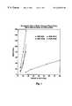
- RCcomprises a conventional roller cone bit for reference purposes
- FC 1is a conventional polycrystalline diamond compact (PDC) cutter-equipped rotary drag bit having cutters backraked at 20°
- FC 2is the directional version of the same bit with 30° backraked cutters.
- the TOB at a given WOB for FC 2which corresponds to its face aggressiveness, can be as much as 30% less than for FC 1 . Therefore, FC 2 is less affected by the sudden load variations inherent in directional drilling.
- FIG. 1it can also be seen that the less aggressive FC 2 bit exhibits a markedly reduced ROP for a given WOB, in comparison to FIG. 2 .
- a bitmay demonstrate the less aggressive characteristics of a conventional directional bit such as FC 2 for non-linear drilling without sacrificing ROP to the same degree when WOB is increased to drill a linear borehole segment.
- U.S. Pat. No. Re 32,036 to Dennisdiscloses such a chamfered cutting edge, disc-shaped PDC cutter comprising a polycrystalline diamond table formed under high pressure and high temperature conditions onto a supporting substrate of tungsten carbide.
- a typical chamfer size and anglewould be 0.010 inch (measured radially and looking at and perpendicular to the cutting face) oriented at a 45° angle with respect to the longitudinal cutter axis, thus providing a larger radial width as measured on the chamfer surface itself.
- Multi-chamfered PDC cuttersare also known in the art, as taught by Cooley et al. U.S. Pat. No. 5,437,343, assigned to the assignee of the present invention. Rounded, rather than chamfered, cutting edges are also known, as disclosed in U.S. Pat. No. 5,016,718 to Tandberg.
- Such cuttersinclude a cutting face bearing a large chamfer or “rake land” thereon adjacent the cutting edge, which rake land may exceed 0.050 inch in width, measured radially and across the surface of the rake land itself.
- Other cutters employing a relatively large chamfer without such a great depth of diamond tableare also known.
- varying chamfer size and chamfer rake angle of various PDC cutters as a function of, or in relationship to, cutter redundancy at varying radial locations on the bit facemay be employed to provide a bit exhibiting relatively low aggressiveness and good stability while affording adequate side cutting capability for non-linear drilling, as well as providing greater ROP when drilling linear borehole segments than conventional directional or steerable bits with highly backraked cutters.
- the present inventioncomprises a rotary drag bit equipped with PDC cutters, wherein cutters in the low cutter redundancy center region of the bit exhibit a relatively large chamfer and are oriented at a relatively large backrake, while chamfer size, as well as chamfer rake angle decreases in cutters located more toward the outer region, or gage, of the bit, wherein higher cutter redundancy is employed.
- Such a bit designnoticeably changes the ROP and TOB versus WOB characteristics for the bit from the linear, single slope curves shown in FIGS. 1 and 2 for FC 1 and FC 2 to exponential, dual-slope curves as shown with respect to a bit FC 3 according to the invention.
- the chamfer sizepredominantly determines at which ROP or WOB level the break in between the two slopes occurs, while the chamfer backrake angle predominantly determines curve slopes at low WOB, and cutter backrake angles dictate the slopes at high WOB.
- the chamfer backrake angle with respect to the formation being cutmay be modified by actually changing the chamfer angle on the cutter, changing the backrake angle of the cutter itself, or a combination of the two.
- different slopes at low WOBmay be achieved for bits employing cutters with similar chamfer angles, but disposed at different cutter backrake angles, or bits employing cutters with different chamfer angles, but disposed at similar cutter backrake angles.
- chamfer size and angle of cutters placed at a variety of radial locations over the face of a bitmay be varied as a function of, or in relation to, cutter redundancy at the various locations.
- FIG. 1comprises a graphical representation of ROP versus WOB characteristics of various rotary drill bits in drilling Mancos Shale at 2000 psi bottomhole pressure;
- FIG. 2comprises a graphical representation of TOB versus WOB characteristics of various rotary drill bits in drilling Mancos Shale at 2,000 psi bottomhole pressure;
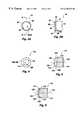
- FIG. 3Acomprises a frontal view of a small chamfer PDC cutter usable with the present invention.
- FIG. 3Bcomprises a side sectional view of the small chamfer PDC cutter of FIG. 3A, taken along section lines B—B;
- FIG. 4comprises a frontal view of a large chamfer PDC cutter usable with the present invention
- FIG. 5comprises a side sectional view of a first internal configuration for the large chamfer PDC cutter of FIG. 4;
- FIG. 6comprises a side sectional view of a second internal configuration for the large chamfer PDC cutter of FIG. 4;
- FIG. 7comprises a side perspective view of a PDC-equipped rotary drag bit according to the present invention.
- FIG. 8comprises a face view of the bit of FIG. 7;
- FIG. 9comprises an enlarged, oblique face view of a single blade of the bit of FIG. 7, illustrating the varying cutter chamfer sizes and angles and cutter rake angles employed;
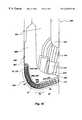
- FIG. 10comprises a quarter-sectional side schematic of a bit having a profile such as that of FIG. 7, with the cutter locations rotated to a single radius extending from the bit centerline to the gage to show the radial bit face locations of the various cutter chamfer sizes and angles, and cutter backrake angles, employed in the bit; and
- FIG. 11comprises a side view of a PDC cutter as employed with the present invention, depicting the effects of chamfer backrake and cutter backrake.
- FIGS. 3A and 3Bdepict an exemplary “small chamfer” cutter 10 comprised of a superabrasive, PDC table 12 , supported by a tungsten carbide (WC) substrate 14 , as known in the art.
- the interface 16 between the PDC table 12 and the substrate 14may be planar or non-planar, according to many varying designs for same as known in the art.
- Cutter 10is substantially cylindrical, and symmetrical about longitudinal axis 18 , although such symmetry is not required and non-symmetrical cutters are known in the art.
- Cutting face 20 of cutter 10to be oriented on a bit facing generally in the direction of bit rotation, extends substantially transversely to such direction, and to axis 18 .
- the surface 22 of the central portion of cutting face 20is planar, as shown, although concave, convex, ridged or other substantially, but not exactly, planar surfaces may be employed.
- a chamfer 24extends from the periphery of surface 22 to cutting edge 26 at the sidewall 28 of PDC table 12 .
- Chamfer 24 and cutting edge 26may extend about the entire periphery of PDC table 12 , or only along a periphery portion to be located adjacent the formation to be cut.
- Chamfer 24may comprise the aforementioned 0.010 inch by 45° angle conventional chamfer, or the chamfer may lie at some other angle, as referenced with respect to the chamfer 124 of cutter 110 described below.
- chamfer sizes within a range of 0.005 to about 0.020 inchare contemplated as generally providing a “small” chamfer for the practice of the invention. It should also be noted that cutters exhibiting substantially no visible chamfer may be employed for certain applications in selected outer regions of the bit.
- FIGS. 4 through 6depict an exemplary “large chamfer” cutter 110 comprised of a superabrasive, PDC table 112 supported by a WC substrate 114 .
- the interface 116 between the PDC table 112 and the substrate 114may be planar or non-planar, according to many varying designs for same as known in the art (see especially FIGS. 5 and 6 ).
- Cutter 110is substantially cylindrical, and symmetrical about longitudinal axis 118 , although such symmetry is not required and non-symmetrical cutters are known in the art.
- Cutting face 120 of cutter 110to be oriented on a bit facing generally in the direction of bit rotation, extends substantially transversely to such direction, and to axis 118 .
- the surface 122 of the central portion of cutting face 120is planar, as shown, although concave, convex, ridged or other substantially, but not exactly, planar surfaces may be employed.
- a chamfer 124extends from the periphery of surface 122 to cutting edge 126 at the sidewall 128 of PDC table 112 .
- Chamfer 124 and cutting edge 126may extend about the entire periphery of PDC table 112 , or only along a periphery portion to be located adjacent the formation to be cut.
- Chamfer 124may comprise a surface oriented at 45° to axis 118 , of a width, measured radially and looking at and perpendicular to the cutting face 120 , ranging upward in magnitude from about 0.030 inch, and generally lying within a range of about 0.030 to 0.060 inch in width.
- Chamfer angles of about 10° to about 80° to axis 118are believed to have utility, with angles in the range of about 30° to about 60° being preferred for most applications.
- the effective angle of a chamfer relative to the formation face being cutmay also be altered by changing the backrake of a cutter.
- FIG. 5illustrates one internal configuration for cutter 110 , wherein PDC table 112 is extremely thick, on the order of 0.070 inch or greater, in accordance with the teachings of the aforementioned '076 application.
- FIG. 6illustrates a second internal configuration for cutter 110 , wherein the front face 115 of substrate 114 is frustoconical in configuration, and PDC table 112 , of substantially constant depth, substantially conforms to the shape of front face 115 to provide a large chamfer of a desired width without requiring the large PDC diamond mass of the '076 application.
- FIGS. 7 through 10depict a rotary drag bit 200 according to the invention.
- Bit 200includes a body 202 having a face 204 and including a plurality (in this instance, six) of generally radially oriented blades 206 extending above the bit face 204 to a gage 207 .
- Junk slots 208lie between adjacent blades 206 .
- a plurality of nozzles 210provides drilling fluid from plenum 212 (FIG. 10) within the bit body 202 and received through passages 214 (FIG. 10) to the bit face 204 . Formation cuttings generated during a drilling operation are transported by the drilling fluid across bit face 204 through fluid courses 216 communicating with respective junk slots 208 .
- Shank 220includes a threaded pin connection 222 , as known in the art, although other connection types may be employed.
- the profile 224 of the bit face 204is illustrated in FIG. 10, wherein bit 200 is shown adjacent a subterranean rock formation 40 at the bottom of the well bore.
- First region 226 and second region 228 on profile 224face adjacent rock zones 42 and 44 of formation 40 and respectively carry large chamfer cutters 110 and small chamfer cutters 10 .
- First region 226may be said to comprise the cone 230 of the bit profile 224 , as illustrated, whereas second region 228 may be said to comprise the nose 232 and, flank 234 and extend to shoulder 236 of profile 224 , terminating at gage 207 .
- large chamfer cutters 110may comprise cutters having PDC tables in excess of 0.070inch depth, and preferably about 0.080 to 0.090 inch depth, with chamfers 124 of about a 0.030 to 0.060 inch width, looking at and perpendicular to the cutting face 120 , and oriented at a 45° angle to the cutter axis 118 .
- the cutters themselves, as disposed in first region 226are backraked at 20° to the bit profile (see cutters 110 shown partially in broken lines in FIG. 10 to denote 20° backrake) at each respective cutter location, thus providing chamfers 124 with a 65° backrake.
- Cutters 10may comprise conventionally-chamfered cutters having about a 0.030 inch PDC table thickness, and about a 0.010 to 0.020 inch chamfer width looking at and perpendicular to cutting face 20 , with chamfers 24 oriented at a 45° angle to the cutter axis 18 . Cutters 10 are themselves backraked at 15° on nose 232 , providing a 60° chamfer backrake, while cutter backrake is further reduced to 10° at the flank 234 , shoulder 236 and on the gage 207 of bit 200 , resulting in a 55° chamfer backrake.
- the PDC cutters 10 immediately above gage 207include preformed flats thereon oriented parallel to the longitudinal axis of the bit 200 , as known in the art.
- large chamfer cutters 110may optionally be employed, but oriented at a 10° cutter backrake.
- the chamfer angle of cutters 110 in each of first region 226 and shoulder 236may be other than 45°.
- 70° chamfer anglesmay be employed with chamfer widths (looking vertically at the cutting face of the cutter) in the range of about 0.035 to 0.045 inch, cutters 110 being disposed at appropriate backrakes to achieve the desired chamfer rake angles in the respective regions.
- a boundary regionmay exist between first and second regions 226 and 228 .
- rock zone 46bridging the adjacent edges of rock zones 42 and 44 of formation 40 , may comprise an area wherein demands on cutters and the strength of the formation are always in transition due to bit dynamics.
- the rock zone 46may initiate the presence of a third region on the bit profile, wherein a third size of cutter chamfer is desirable.
- the annular area of profile 224 opposing zone 46may be populated with cutters of both types (i.e., width and chamfer angle) and employing backrakes respectively employed in first region 226 and those of second region 228 , or cutters with chamfer sizes, angles and cutter backrakes intermediate those of the cutters in first and second regions 226 and 228 may be employed.
- Bit 200equipped as described with a combination of small chamfer cutters 10 and large chamfer cutters 110 , will drill with an ROP approaching that of conventional, non-directional bits equipped only with small chamfer cutters, but will maintain superior stability, and will drill far faster than a conventional directional drill bit equipped only with large chamfer cutters.
- the benefits achieved by the present inventionresult from the aforementioned effects of selective variation of chamfer size, chamfer backrake angle and cutter backrake angle.
- the size (width) of the chamfer 124 of the large chamfer cutters 110 at the center of the bitcan be selected to maintain non-aggressive characteristics in the bit up to a certain WOB or ROP, denoted in FIGS. 1 and 2 as the “break” in the curve slopes for bit FC 3 .
- WOBWOB
- ROPthe chamfer backrake angles ⁇ 1
- the larger the chamfer 124the greater WOB must be applied before the bit enters the second, steeper-slope portions of the curves.
- a non-aggressive character for the bitmay be maintained by drilling to a first depth of cut (DOC 1 ) associated with low WOB, wherein the cut is taken substantially within the chamfer 124 of the large chamfer cutters 110 disposed in the center region of the bit.
- DOC 1first depth of cut
- the effective backrake angle of the cutting face 120 of cutter 110is the chamfer backrake ⁇ 1
- the effective included angle ⁇ 1 between the cutting face 120 and the formation 300is relatively small.
- WOBis increased so that the depth of cut (DOC 2 ) extends above the chamfers 124 on the cutting faces 120 of the large chamfer cutters to provide a larger effective included angle ⁇ 2 (and smaller effective cutting face backrake angle ⁇ 2) between the cutting face 120 and the formation 300 , rendering the cutters 110 more aggressive and thus increasing ROP for a given WOB above the break point of the curve of FIG. 1 .
- this conditionis also demonstrated by a perceptible increase in the slope of the TOB versus WOB curve above a certain WOB level.
- WOBmay have to be applied to cause the bit to become more aggressive and increase ROP for linear drilling.
- the chamfer backrake angle ⁇ 1 of the large chamfer cutters 110may be employed to control DOC for a given WOB below a threshold WOB wherein DOC exceeds the chamfer depth perpendicular to the formation.
- the chamfer rake angle ⁇ 1predominantly determines the slopes of the ROP ⁇ WOB and TOB ⁇ WOB curves of FIGS. 1 and 2 at low WOB and below the breaks in the curves, since the cutters 110 apparently engage the formation to a DOC 1 residing substantially within the chamfer 124 .
- selection of the backrake angles ⁇ of the cutters 110 themselvesmay be employed to predominantly determine the slopes of the ROP ⁇ WOB and TOB ⁇ WOB curves at high WOB and above the breaks in the curves, since the cutters 110 will be engaged with the formation to a DOC 2 such that portions of the cutting face centers of the cutters 110 (i.e., above the chamfers 124 ) will be engaged with the formation 300 .
- cutter backrake ⁇will largely dominate effective cutting face backrake angles (now ⁇ 2) with respect to the formation 300 , regardless of the chamfer rake angles ⁇ 1.
- cutter rake backrake angles ⁇may also be used to alter the chamfer rake angles ⁇ 1 for purposes of determining bit performance during relatively low WOB drilling.
- chamfer size and chamfer backrake angle of the large chamfer cuttersmay be employed to optimize the performance of a drill bit with respect to the output characteristics of a downhole motor driving the bit during steerable or non-linear drilling of a borehole segment. Such optimization may be effected by choosing a chamfer size so that the bit remains non-aggressive under the maximum WOB to be applied during steerable or non-linear drilling of the formation or formations in question, and choosing a chamfer backrake angle so that the torque demands made by the bit within the applied WOB range during such steerable drilling do not exceed torque output available from the motor, thus avoiding stalling.
- the chamfer widths employed on different regions of the bit facemay be selected in proportion to cutter redundancy or density at such locations.
- a center region of the bitsuch as within a cone surrounding the bit centerline (see FIGS. 7 through 10 and above discussion), may have only a single cutter (allowing for some radial cutter overlap) at each of several locations extending radially outward from the centerline or longitudinal axis of the bit. In other words, there is only “single” cutter redundancy at such cutter locations.
- An outer region of the bitmay, on the other hand, exhibit several cutters at substantially the same radial location. It may be desirable to provide three cutters at substantially a single radial location in the outer region, providing substantially triple cutter redundancy. In a transition region between the inner and outer regions, such as on the boundary between the cone and the nose, there may be an intermediate cutter redundancy, such as substantially double redundancy, or two cutters at substantially each radial location in that region.
- cutters at single redundancy locationsmay exhibit chamfer widths of between about 0.030 and 0.060 inch, while those at double redundancy locations may exhibit chamfer widths of between about 0.020 and 0.040 inch, and cutters at triple redundancy locations may exhibit chamfer widths of between about 0.010 and 0.020 inch.
- Rake angles of cutters in relation to their positions on the bit facehave previously been discussed with regard to FIGS. 7 through 10. However, it will be appreciated that differences in the chamfer angles from the exemplary 45° angles discussed above may necessitate differences in the relative cutter backrake angles employed in and within the different regions of the bit face in comparison to those of the example.
Landscapes
- Engineering & Computer Science (AREA)
- Geology (AREA)
- Life Sciences & Earth Sciences (AREA)
- Mining & Mineral Resources (AREA)
- Physics & Mathematics (AREA)
- Environmental & Geological Engineering (AREA)
- Fluid Mechanics (AREA)
- Mechanical Engineering (AREA)
- General Life Sciences & Earth Sciences (AREA)
- Geochemistry & Mineralogy (AREA)
- Chemical & Material Sciences (AREA)
- Crystallography & Structural Chemistry (AREA)
- Earth Drilling (AREA)
- Drilling Tools (AREA)
Abstract
Description
Claims (53)
Priority Applications (9)
| Application Number | Priority Date | Filing Date | Title |
|---|---|---|---|
| US08/925,525US6230828B1 (en) | 1997-09-08 | 1997-09-08 | Rotary drilling bits for directional drilling exhibiting variable weight-on-bit dependent cutting characteristics |
| GB9819300AGB2329203B (en) | 1997-09-08 | 1998-09-07 | Rotary drill bits for directional drilling exhibiting variable weight-on-bit dependent cutting characteristics |
| GB0129414AGB2367578B (en) | 1997-09-08 | 1998-09-07 | Rotary bits for directional drilling exhibiting variable weight-on-bit cutting characteristics |
| GB0129417AGB2367579B (en) | 1997-09-08 | 1998-09-07 | Rotary drill bits for directional drilling exhibiting variable weight-on-bit cutting characteristics |
| BE9800658ABE1012752A5 (en) | 1997-09-08 | 1998-09-08 | Rotary drill bits DIRECTIONAL DRILLING FOR HAVING CUP FEATURES VARIABLE WEIGHT APPLY DEPENDING ON THE DRILL. |
| IT1998TO000754AIT1303567B1 (en) | 1997-09-08 | 1998-09-08 | ROTARY DRILLING TOOL FOR DIRECTIONAL DRILLING WITH VARIABLE CUTTING FEATURES ACCORDING TO THE AGENT LOAD |
| US09/748,771US6672406B2 (en) | 1997-09-08 | 2000-12-21 | Multi-aggressiveness cuttting face on PDC cutters and method of drilling subterranean formations |
| US09/854,765US6443249B2 (en) | 1997-09-08 | 2001-05-14 | Rotary drill bits for directional drilling exhibiting variable weight-on-bit dependent cutting characteristics |
| US10/233,329US7000715B2 (en) | 1997-09-08 | 2002-08-30 | Rotary drill bits exhibiting cutting element placement for optimizing bit torque and cutter life |
Applications Claiming Priority (1)
| Application Number | Priority Date | Filing Date | Title |
|---|---|---|---|
| US08/925,525US6230828B1 (en) | 1997-09-08 | 1997-09-08 | Rotary drilling bits for directional drilling exhibiting variable weight-on-bit dependent cutting characteristics |
Related Child Applications (2)
| Application Number | Title | Priority Date | Filing Date |
|---|---|---|---|
| US09/748,771Continuation-In-PartUS6672406B2 (en) | 1997-09-08 | 2000-12-21 | Multi-aggressiveness cuttting face on PDC cutters and method of drilling subterranean formations |
| US09/854,765ContinuationUS6443249B2 (en) | 1997-09-08 | 2001-05-14 | Rotary drill bits for directional drilling exhibiting variable weight-on-bit dependent cutting characteristics |
Publications (1)
| Publication Number | Publication Date |
|---|---|
| US6230828B1true US6230828B1 (en) | 2001-05-15 |
Family
ID=25451855
Family Applications (2)
| Application Number | Title | Priority Date | Filing Date |
|---|---|---|---|
| US08/925,525Expired - LifetimeUS6230828B1 (en) | 1997-09-08 | 1997-09-08 | Rotary drilling bits for directional drilling exhibiting variable weight-on-bit dependent cutting characteristics |
| US09/854,765Expired - LifetimeUS6443249B2 (en) | 1997-09-08 | 2001-05-14 | Rotary drill bits for directional drilling exhibiting variable weight-on-bit dependent cutting characteristics |
Family Applications After (1)
| Application Number | Title | Priority Date | Filing Date |
|---|---|---|---|
| US09/854,765Expired - LifetimeUS6443249B2 (en) | 1997-09-08 | 2001-05-14 | Rotary drill bits for directional drilling exhibiting variable weight-on-bit dependent cutting characteristics |
Country Status (4)
| Country | Link |
|---|---|
| US (2) | US6230828B1 (en) |
| BE (1) | BE1012752A5 (en) |
| GB (1) | GB2329203B (en) |
| IT (1) | IT1303567B1 (en) |
Cited By (29)
| Publication number | Priority date | Publication date | Assignee | Title |
|---|---|---|---|---|
| US6536543B2 (en)* | 2000-12-06 | 2003-03-25 | Baker Hughes Incorporated | Rotary drill bits exhibiting sequences of substantially continuously variable cutter backrake angles |
| US6637527B1 (en)* | 2000-06-08 | 2003-10-28 | Smith International, Inc. | Cutting structure for roller cone drill bits |
| US6810971B1 (en) | 2002-02-08 | 2004-11-02 | Hard Rock Drilling & Fabrication, L.L.C. | Steerable horizontal subterranean drill bit |
| US6810973B2 (en) | 2002-02-08 | 2004-11-02 | Hard Rock Drilling & Fabrication, L.L.C. | Steerable horizontal subterranean drill bit having offset cutting tooth paths |
| US6810972B2 (en) | 2002-02-08 | 2004-11-02 | Hard Rock Drilling & Fabrication, L.L.C. | Steerable horizontal subterranean drill bit having a one bolt attachment system |
| US6814168B2 (en) | 2002-02-08 | 2004-11-09 | Hard Rock Drilling & Fabrication, L.L.C. | Steerable horizontal subterranean drill bit having elevated wear protector receptacles |
| US6827159B2 (en) | 2002-02-08 | 2004-12-07 | Hard Rock Drilling & Fabrication, L.L.C. | Steerable horizontal subterranean drill bit having an offset drilling fluid seal |
| GB2421042A (en)* | 2004-12-10 | 2006-06-14 | Smith International | Drill bit with secondary cutters for hard formations |
| US20060185901A1 (en)* | 2005-02-22 | 2006-08-24 | Sinor L A | Drilling tool equipped with improved cutting element layout to reduce cutter damage through formation changes, methods of design and operation thereof |
| GB2434391A (en)* | 2004-12-10 | 2007-07-25 | Smith International | Drill bit with secondary cutters for hard formations |
| US20090084607A1 (en)* | 2007-10-01 | 2009-04-02 | Ernst Stephen J | Drill bits and tools for subterranean drilling |
| US20090084606A1 (en)* | 2007-10-01 | 2009-04-02 | Doster Michael L | Drill bits and tools for subterranean drilling |
| US20090200081A1 (en)* | 2008-02-08 | 2009-08-13 | X-Treme Bits & Downhole Tooling Ltd. | Shear cutter drill bit |
| US20090272583A1 (en)* | 2005-01-17 | 2009-11-05 | Us Synthetic Corporation | Superabrasive inserts including an arcuate peripheral surface |
| US20100193248A1 (en)* | 2009-01-30 | 2010-08-05 | Baker Hughes Incorporated | Methods, systems, and tool assemblies for distributing weight between an earth-boring rotary drill bit and a reamer device |
| US20100252331A1 (en)* | 2009-04-01 | 2010-10-07 | High Angela D | Methods for forming boring shoes for wellbore casing, and boring shoes and intermediate structures formed by such methods |
| US20100326741A1 (en)* | 2009-06-29 | 2010-12-30 | Baker Hughes Incorporated | Non-parallel face polycrystalline diamond cutter and drilling tools so equipped |
| US20110024200A1 (en)* | 2009-07-08 | 2011-02-03 | Baker Hughes Incorporated | Cutting element and method of forming thereof |
| US20110023377A1 (en)* | 2009-07-27 | 2011-02-03 | Baker Hughes Incorporated | Abrasive article and method of forming |
| US20110031036A1 (en)* | 2009-08-07 | 2011-02-10 | Baker Hughes Incorporated | Superabrasive cutters with grooves on the cutting face, and drill bits and drilling tools so equipped |
| US8224783B1 (en)* | 2000-09-26 | 2012-07-17 | Conocophillips Company | Information management system |
| US20130238245A1 (en)* | 2010-11-10 | 2013-09-12 | Shilin Chen | System and method of configuring drilling tools utilizing a critical depth of cut control curve |
| US8887839B2 (en) | 2009-06-25 | 2014-11-18 | Baker Hughes Incorporated | Drill bit for use in drilling subterranean formations |
| US8936659B2 (en) | 2010-04-14 | 2015-01-20 | Baker Hughes Incorporated | Methods of forming diamond particles having organic compounds attached thereto and compositions thereof |
| US8978788B2 (en) | 2009-07-08 | 2015-03-17 | Baker Hughes Incorporated | Cutting element for a drill bit used in drilling subterranean formations |
| US9140072B2 (en) | 2013-02-28 | 2015-09-22 | Baker Hughes Incorporated | Cutting elements including non-planar interfaces, earth-boring tools including such cutting elements, and methods of forming cutting elements |
| CN106907112A (en)* | 2017-05-05 | 2017-06-30 | 宜昌神达石油机械有限公司 | A kind of drilling well PDC drill bit |
| CN110359856A (en)* | 2018-02-10 | 2019-10-22 | 西南石油大学 | Combined type diamond bit with slew buffer structure |
| CN112709536A (en)* | 2019-10-25 | 2021-04-27 | 中国石油化工股份有限公司 | PDC drill bit that anti awl was milled |
Families Citing this family (38)
| Publication number | Priority date | Publication date | Assignee | Title |
|---|---|---|---|---|
| US6269893B1 (en) | 1999-06-30 | 2001-08-07 | Smith International, Inc. | Bi-centered drill bit having improved drilling stability mud hydraulics and resistance to cutter damage |
| US6460631B2 (en) | 1999-08-26 | 2002-10-08 | Baker Hughes Incorporated | Drill bits with reduced exposure of cutters |
| US6298930B1 (en)* | 1999-08-26 | 2001-10-09 | Baker Hughes Incorporated | Drill bits with controlled cutter loading and depth of cut |
| US6615934B2 (en)* | 2001-08-15 | 2003-09-09 | Smith International, Inc. | PDC drill bit having cutting structure adapted to improve high speed drilling performance |
| US7441612B2 (en)* | 2005-01-24 | 2008-10-28 | Smith International, Inc. | PDC drill bit using optimized side rake angle |
| US8360174B2 (en) | 2006-03-23 | 2013-01-29 | Schlumberger Technology Corporation | Lead the bit rotary steerable tool |
| US8316964B2 (en) | 2006-03-23 | 2012-11-27 | Schlumberger Technology Corporation | Drill bit transducer device |
| US8522897B2 (en) | 2005-11-21 | 2013-09-03 | Schlumberger Technology Corporation | Lead the bit rotary steerable tool |
| US8225883B2 (en) | 2005-11-21 | 2012-07-24 | Schlumberger Technology Corporation | Downhole percussive tool with alternating pressure differentials |
| US8267196B2 (en) | 2005-11-21 | 2012-09-18 | Schlumberger Technology Corporation | Flow guide actuation |
| US8297375B2 (en) | 2005-11-21 | 2012-10-30 | Schlumberger Technology Corporation | Downhole turbine |
| US7571780B2 (en) | 2006-03-24 | 2009-08-11 | Hall David R | Jack element for a drill bit |
| US8297378B2 (en) | 2005-11-21 | 2012-10-30 | Schlumberger Technology Corporation | Turbine driven hammer that oscillates at a constant frequency |
| US8528664B2 (en) | 2005-11-21 | 2013-09-10 | Schlumberger Technology Corporation | Downhole mechanism |
| US20070205024A1 (en)* | 2005-11-30 | 2007-09-06 | Graham Mensa-Wilmot | Steerable fixed cutter drill bit |
| US8141665B2 (en) | 2005-12-14 | 2012-03-27 | Baker Hughes Incorporated | Drill bits with bearing elements for reducing exposure of cutters |
| US8011457B2 (en) | 2006-03-23 | 2011-09-06 | Schlumberger Technology Corporation | Downhole hammer assembly |
| GB2453875C (en) | 2006-10-02 | 2009-09-16 | Smith International | Drill bits with dropping tendencies |
| US7866416B2 (en) | 2007-06-04 | 2011-01-11 | Schlumberger Technology Corporation | Clutch for a jack element |
| US7703557B2 (en) | 2007-06-11 | 2010-04-27 | Smith International, Inc. | Fixed cutter bit with backup cutter elements on primary blades |
| US7814997B2 (en) | 2007-06-14 | 2010-10-19 | Baker Hughes Incorporated | Interchangeable bearing blocks for drill bits, and drill bits including same |
| US7721826B2 (en) | 2007-09-06 | 2010-05-25 | Schlumberger Technology Corporation | Downhole jack assembly sensor |
| US7967083B2 (en)* | 2007-09-06 | 2011-06-28 | Schlumberger Technology Corporation | Sensor for determining a position of a jack element |
| US9016407B2 (en) | 2007-12-07 | 2015-04-28 | Smith International, Inc. | Drill bit cutting structure and methods to maximize depth-of-cut for weight on bit applied |
| WO2009146078A1 (en) | 2008-04-01 | 2009-12-03 | Smith International, Inc. | Fixed cutter bit with backup cutter elements on secondary blades |
| RU2374420C1 (en) | 2008-12-29 | 2009-11-27 | Общество с ограниченной ответственностью Научно-производственное предприятие "БУРИНТЕХ" (ООО НПП "БУРИНТЕХ") | Blade drill bit |
| US8943663B2 (en) | 2009-04-15 | 2015-02-03 | Baker Hughes Incorporated | Methods of forming and repairing cutting element pockets in earth-boring tools with depth-of-cut control features, and tools and structures formed by such methods |
| US20100276200A1 (en)* | 2009-04-30 | 2010-11-04 | Baker Hughes Incorporated | Bearing blocks for drill bits, drill bit assemblies including bearing blocks and related methods |
| US9309723B2 (en) | 2009-10-05 | 2016-04-12 | Baker Hughes Incorporated | Drill bits and tools for subterranean drilling, methods of manufacturing such drill bits and tools and methods of directional and off center drilling |
| US8511405B2 (en)* | 2010-04-30 | 2013-08-20 | Ryan Clint Frazier | Drill bit with tiered cutters |
| US8858665B2 (en) | 2011-04-28 | 2014-10-14 | Robert Frushour | Method for making fine diamond PDC |
| US8741010B2 (en) | 2011-04-28 | 2014-06-03 | Robert Frushour | Method for making low stress PDC |
| US8974559B2 (en) | 2011-05-12 | 2015-03-10 | Robert Frushour | PDC made with low melting point catalyst |
| US9061264B2 (en) | 2011-05-19 | 2015-06-23 | Robert H. Frushour | High abrasion low stress PDC |
| US8828110B2 (en) | 2011-05-20 | 2014-09-09 | Robert Frushour | ADNR composite |
| CN104136705A (en)* | 2011-12-29 | 2014-11-05 | 史密斯国际有限公司 | Spacing of rolling cutters on a fixed cutter bit |
| US9464490B2 (en) | 2012-05-03 | 2016-10-11 | Smith International, Inc. | Gage cutter protection for drilling bits |
| CN111520079A (en)* | 2020-06-23 | 2020-08-11 | 西南石油大学 | A PDC drill blade with offset crown profile |
Citations (19)
| Publication number | Priority date | Publication date | Assignee | Title |
|---|---|---|---|---|
| US4342368A (en) | 1977-08-18 | 1982-08-03 | Kennametal Inc. | Rotary drills and drill bits |
| USRE32036E (en) | 1980-06-11 | 1985-11-26 | Strata Bit Corporation | Drill bit |
| US4558753A (en)* | 1983-02-22 | 1985-12-17 | Nl Industries, Inc. | Drag bit and cutters |
| US4607711A (en) | 1984-02-29 | 1986-08-26 | Shell Oil Company | Rotary drill bit with cutting elements having a thin abrasive front layer |
| US4660659A (en)* | 1983-02-22 | 1987-04-28 | Nl Industries, Inc. | Drag type drill bit |
| US4673044A (en)* | 1985-08-02 | 1987-06-16 | Eastman Christensen Co. | Earth boring bit for soft to hard formations |
| US4792001A (en) | 1986-03-27 | 1988-12-20 | Shell Oil Company | Rotary drill bit |
| US4808044A (en)* | 1986-04-30 | 1989-02-28 | Mitsubishi Kinzoku Kabushiki Kaisha | Insert cutter |
| US4926950A (en) | 1986-03-27 | 1990-05-22 | Shell Oil Company | Method for monitoring the wear of a rotary type drill bit |
| US4932484A (en)* | 1989-04-10 | 1990-06-12 | Amoco Corporation | Whirl resistant bit |
| US5016718A (en) | 1989-01-26 | 1991-05-21 | Geir Tandberg | Combination drill bit |
| US5437343A (en) | 1992-06-05 | 1995-08-01 | Baker Hughes Incorporated | Diamond cutters having modified cutting edge geometry and drill bit mounting arrangement therefor |
| US5443565A (en)* | 1994-07-11 | 1995-08-22 | Strange, Jr.; William S. | Drill bit with forward sweep cutting elements |
| US5467836A (en) | 1992-01-31 | 1995-11-21 | Baker Hughes Incorporated | Fixed cutter bit with shear cutting gage |
| US5549171A (en)* | 1994-08-10 | 1996-08-27 | Smith International, Inc. | Drill bit with performance-improving cutting structure |
| US5605198A (en) | 1993-12-09 | 1997-02-25 | Baker Hughes Incorporated | Stress related placement of engineered superabrasive cutting elements on rotary drag bits |
| US5706906A (en) | 1996-02-15 | 1998-01-13 | Baker Hughes Incorporated | Superabrasive cutting element with enhanced durability and increased wear life, and apparatus so equipped |
| GB2323398A (en) | 1997-02-14 | 1998-09-23 | Baker Hughes Inc | Superabrasive cutting element |
| US5960896A (en)* | 1997-09-08 | 1999-10-05 | Baker Hughes Incorporated | Rotary drill bits employing optimal cutter placement based on chamfer geometry |
Family Cites Families (1)
| Publication number | Priority date | Publication date | Assignee | Title |
|---|---|---|---|---|
| DE69221983D1 (en)* | 1991-10-09 | 1997-10-09 | Smith International | Diamond cutting insert with a convex cutting surface |
- 1997
- 1997-09-08USUS08/925,525patent/US6230828B1/ennot_activeExpired - Lifetime
- 1998
- 1998-09-07GBGB9819300Apatent/GB2329203B/ennot_activeExpired - Fee Related
- 1998-09-08BEBE9800658Apatent/BE1012752A5/ennot_activeIP Right Cessation
- 1998-09-08ITIT1998TO000754Apatent/IT1303567B1/enactiveIP Right Grant
- 2001
- 2001-05-14USUS09/854,765patent/US6443249B2/ennot_activeExpired - Lifetime
Patent Citations (20)
| Publication number | Priority date | Publication date | Assignee | Title |
|---|---|---|---|---|
| US4342368A (en) | 1977-08-18 | 1982-08-03 | Kennametal Inc. | Rotary drills and drill bits |
| USRE32036E (en) | 1980-06-11 | 1985-11-26 | Strata Bit Corporation | Drill bit |
| US4558753A (en)* | 1983-02-22 | 1985-12-17 | Nl Industries, Inc. | Drag bit and cutters |
| US4660659A (en)* | 1983-02-22 | 1987-04-28 | Nl Industries, Inc. | Drag type drill bit |
| US4607711A (en) | 1984-02-29 | 1986-08-26 | Shell Oil Company | Rotary drill bit with cutting elements having a thin abrasive front layer |
| US4673044A (en)* | 1985-08-02 | 1987-06-16 | Eastman Christensen Co. | Earth boring bit for soft to hard formations |
| US4792001A (en) | 1986-03-27 | 1988-12-20 | Shell Oil Company | Rotary drill bit |
| US4926950A (en) | 1986-03-27 | 1990-05-22 | Shell Oil Company | Method for monitoring the wear of a rotary type drill bit |
| US4808044A (en)* | 1986-04-30 | 1989-02-28 | Mitsubishi Kinzoku Kabushiki Kaisha | Insert cutter |
| US5016718A (en) | 1989-01-26 | 1991-05-21 | Geir Tandberg | Combination drill bit |
| US4932484A (en)* | 1989-04-10 | 1990-06-12 | Amoco Corporation | Whirl resistant bit |
| US5467836A (en) | 1992-01-31 | 1995-11-21 | Baker Hughes Incorporated | Fixed cutter bit with shear cutting gage |
| US5655612A (en) | 1992-01-31 | 1997-08-12 | Baker Hughes Inc. | Earth-boring bit with shear cutting gage |
| US5437343A (en) | 1992-06-05 | 1995-08-01 | Baker Hughes Incorporated | Diamond cutters having modified cutting edge geometry and drill bit mounting arrangement therefor |
| US5605198A (en) | 1993-12-09 | 1997-02-25 | Baker Hughes Incorporated | Stress related placement of engineered superabrasive cutting elements on rotary drag bits |
| US5443565A (en)* | 1994-07-11 | 1995-08-22 | Strange, Jr.; William S. | Drill bit with forward sweep cutting elements |
| US5549171A (en)* | 1994-08-10 | 1996-08-27 | Smith International, Inc. | Drill bit with performance-improving cutting structure |
| US5706906A (en) | 1996-02-15 | 1998-01-13 | Baker Hughes Incorporated | Superabrasive cutting element with enhanced durability and increased wear life, and apparatus so equipped |
| GB2323398A (en) | 1997-02-14 | 1998-09-23 | Baker Hughes Inc | Superabrasive cutting element |
| US5960896A (en)* | 1997-09-08 | 1999-10-05 | Baker Hughes Incorporated | Rotary drill bits employing optimal cutter placement based on chamfer geometry |
Non-Patent Citations (1)
| Title |
|---|
| Search Report Under Section 17 dated Jan. 7, 1999. |
Cited By (58)
| Publication number | Priority date | Publication date | Assignee | Title |
|---|---|---|---|---|
| US6637527B1 (en)* | 2000-06-08 | 2003-10-28 | Smith International, Inc. | Cutting structure for roller cone drill bits |
| US8224783B1 (en)* | 2000-09-26 | 2012-07-17 | Conocophillips Company | Information management system |
| US6536543B2 (en)* | 2000-12-06 | 2003-03-25 | Baker Hughes Incorporated | Rotary drill bits exhibiting sequences of substantially continuously variable cutter backrake angles |
| US6711969B2 (en) | 2000-12-06 | 2004-03-30 | Baker Hughes Incorporated | Methods for designing rotary drill bits exhibiting sequences of substantially continuously variable cutter backrake angles |
| US6810971B1 (en) | 2002-02-08 | 2004-11-02 | Hard Rock Drilling & Fabrication, L.L.C. | Steerable horizontal subterranean drill bit |
| US6810973B2 (en) | 2002-02-08 | 2004-11-02 | Hard Rock Drilling & Fabrication, L.L.C. | Steerable horizontal subterranean drill bit having offset cutting tooth paths |
| US6810972B2 (en) | 2002-02-08 | 2004-11-02 | Hard Rock Drilling & Fabrication, L.L.C. | Steerable horizontal subterranean drill bit having a one bolt attachment system |
| US6814168B2 (en) | 2002-02-08 | 2004-11-09 | Hard Rock Drilling & Fabrication, L.L.C. | Steerable horizontal subterranean drill bit having elevated wear protector receptacles |
| US6827159B2 (en) | 2002-02-08 | 2004-12-07 | Hard Rock Drilling & Fabrication, L.L.C. | Steerable horizontal subterranean drill bit having an offset drilling fluid seal |
| GB2421042A (en)* | 2004-12-10 | 2006-06-14 | Smith International | Drill bit with secondary cutters for hard formations |
| GB2434391A (en)* | 2004-12-10 | 2007-07-25 | Smith International | Drill bit with secondary cutters for hard formations |
| GB2434391B (en)* | 2004-12-10 | 2008-04-16 | Smith International | Drill bit and method of cutting a borehole |
| US20060124358A1 (en)* | 2004-12-10 | 2006-06-15 | Smith International, Inc. | Impact resistant PDC drill bit |
| US8448725B2 (en) | 2004-12-10 | 2013-05-28 | Smith International, Inc. | Impact resistant PDC drill bit |
| US8783388B1 (en) | 2005-01-17 | 2014-07-22 | Us Synthetic Corporation | Superabrasive inserts including an arcuate peripheral surface |
| US8505655B1 (en) | 2005-01-17 | 2013-08-13 | Us Synthetic Corporation | Superabrasive inserts including an arcuate peripheral surface |
| US8272459B2 (en) | 2005-01-17 | 2012-09-25 | Us Synthetic Corporation | Superabrasive inserts including an arcuate peripheral surface |
| US20090272583A1 (en)* | 2005-01-17 | 2009-11-05 | Us Synthetic Corporation | Superabrasive inserts including an arcuate peripheral surface |
| US20080302573A1 (en)* | 2005-02-22 | 2008-12-11 | Baker Hughes Incorporated | Drilling tool for reducing cutter damage when drilling through formation changes, and methods of design and operation thereof |
| US20060185901A1 (en)* | 2005-02-22 | 2006-08-24 | Sinor L A | Drilling tool equipped with improved cutting element layout to reduce cutter damage through formation changes, methods of design and operation thereof |
| US7455125B2 (en) | 2005-02-22 | 2008-11-25 | Baker Hughes Incorporated | Drilling tool equipped with improved cutting element layout to reduce cutter damage through formation changes, methods of design and operation thereof |
| US7703558B2 (en) | 2005-02-22 | 2010-04-27 | Baker Hughes Incorporated | Drilling tool for reducing cutter damage when drilling through formation changes, and methods of design and operation thereof |
| US20090084607A1 (en)* | 2007-10-01 | 2009-04-02 | Ernst Stephen J | Drill bits and tools for subterranean drilling |
| US20090084606A1 (en)* | 2007-10-01 | 2009-04-02 | Doster Michael L | Drill bits and tools for subterranean drilling |
| US20090200081A1 (en)* | 2008-02-08 | 2009-08-13 | X-Treme Bits & Downhole Tooling Ltd. | Shear cutter drill bit |
| US20100193248A1 (en)* | 2009-01-30 | 2010-08-05 | Baker Hughes Incorporated | Methods, systems, and tool assemblies for distributing weight between an earth-boring rotary drill bit and a reamer device |
| US8584776B2 (en)* | 2009-01-30 | 2013-11-19 | Baker Hughes Incorporated | Methods, systems, and tool assemblies for distributing weight between an earth-boring rotary drill bit and a reamer device |
| US20100252331A1 (en)* | 2009-04-01 | 2010-10-07 | High Angela D | Methods for forming boring shoes for wellbore casing, and boring shoes and intermediate structures formed by such methods |
| US8887839B2 (en) | 2009-06-25 | 2014-11-18 | Baker Hughes Incorporated | Drill bit for use in drilling subterranean formations |
| US8327955B2 (en) | 2009-06-29 | 2012-12-11 | Baker Hughes Incorporated | Non-parallel face polycrystalline diamond cutter and drilling tools so equipped |
| US8851206B2 (en) | 2009-06-29 | 2014-10-07 | Baker Hughes Incorporated | Oblique face polycrystalline diamond cutter and drilling tools so equipped |
| US9598909B2 (en) | 2009-06-29 | 2017-03-21 | Baker Hughes Incorporated | Superabrasive cutters with grooves on the cutting face and drill bits and drilling tools so equipped |
| US20100326741A1 (en)* | 2009-06-29 | 2010-12-30 | Baker Hughes Incorporated | Non-parallel face polycrystalline diamond cutter and drilling tools so equipped |
| US9816324B2 (en) | 2009-07-08 | 2017-11-14 | Baker Hughes | Cutting element incorporating a cutting body and sleeve and method of forming thereof |
| US8757299B2 (en) | 2009-07-08 | 2014-06-24 | Baker Hughes Incorporated | Cutting element and method of forming thereof |
| US20110024200A1 (en)* | 2009-07-08 | 2011-02-03 | Baker Hughes Incorporated | Cutting element and method of forming thereof |
| US10309157B2 (en) | 2009-07-08 | 2019-06-04 | Baker Hughes Incorporated | Cutting element incorporating a cutting body and sleeve and an earth-boring tool including the cutting element |
| US8978788B2 (en) | 2009-07-08 | 2015-03-17 | Baker Hughes Incorporated | Cutting element for a drill bit used in drilling subterranean formations |
| US9957757B2 (en) | 2009-07-08 | 2018-05-01 | Baker Hughes Incorporated | Cutting elements for drill bits for drilling subterranean formations and methods of forming such cutting elements |
| US10012030B2 (en) | 2009-07-27 | 2018-07-03 | Baker Hughes, A Ge Company, Llc | Abrasive articles and earth-boring tools |
| US20110023377A1 (en)* | 2009-07-27 | 2011-02-03 | Baker Hughes Incorporated | Abrasive article and method of forming |
| US9174325B2 (en) | 2009-07-27 | 2015-11-03 | Baker Hughes Incorporated | Methods of forming abrasive articles |
| US8500833B2 (en) | 2009-07-27 | 2013-08-06 | Baker Hughes Incorporated | Abrasive article and method of forming |
| US9744646B2 (en) | 2009-07-27 | 2017-08-29 | Baker Hughes Incorporated | Methods of forming abrasive articles |
| US20110031036A1 (en)* | 2009-08-07 | 2011-02-10 | Baker Hughes Incorporated | Superabrasive cutters with grooves on the cutting face, and drill bits and drilling tools so equipped |
| US8739904B2 (en) | 2009-08-07 | 2014-06-03 | Baker Hughes Incorporated | Superabrasive cutters with grooves on the cutting face, and drill bits and drilling tools so equipped |
| US8936659B2 (en) | 2010-04-14 | 2015-01-20 | Baker Hughes Incorporated | Methods of forming diamond particles having organic compounds attached thereto and compositions thereof |
| US9540882B2 (en)* | 2010-11-10 | 2017-01-10 | Halliburton Energy Services, Inc. | System and method of configuring drilling tools utilizing a critical depth of cut control curve |
| US9650835B2 (en)* | 2010-11-10 | 2017-05-16 | Halliburton Energy Services, Inc. | System and method of configuring drilling tools utilizing a critical depth of cut control curve |
| US9523242B2 (en) | 2010-11-10 | 2016-12-20 | Halliburton Energy Services, Inc. | System and method of constant depth of cut control of drilling tools |
| US9506294B2 (en) | 2010-11-10 | 2016-11-29 | Halliburton Energy Services, Inc. | System and method of constant depth of cut control of drilling tools |
| US20130238245A1 (en)* | 2010-11-10 | 2013-09-12 | Shilin Chen | System and method of configuring drilling tools utilizing a critical depth of cut control curve |
| US20130253836A1 (en)* | 2010-11-10 | 2013-09-26 | Shilin Chen | System and method of configuring drilling tools utilizing a critical depth of cut control curve |
| US9140072B2 (en) | 2013-02-28 | 2015-09-22 | Baker Hughes Incorporated | Cutting elements including non-planar interfaces, earth-boring tools including such cutting elements, and methods of forming cutting elements |
| CN106907112A (en)* | 2017-05-05 | 2017-06-30 | 宜昌神达石油机械有限公司 | A kind of drilling well PDC drill bit |
| CN106907112B (en)* | 2017-05-05 | 2023-06-20 | 宜昌神达科技有限公司 | PDC drill bit for well drilling |
| CN110359856A (en)* | 2018-02-10 | 2019-10-22 | 西南石油大学 | Combined type diamond bit with slew buffer structure |
| CN112709536A (en)* | 2019-10-25 | 2021-04-27 | 中国石油化工股份有限公司 | PDC drill bit that anti awl was milled |
Also Published As
| Publication number | Publication date |
|---|---|
| ITTO980754A1 (en) | 2000-03-08 |
| IT1303567B1 (en) | 2000-11-14 |
| GB9819300D0 (en) | 1998-10-28 |
| US6443249B2 (en) | 2002-09-03 |
| US20010030065A1 (en) | 2001-10-18 |
| GB2329203B (en) | 2002-06-12 |
| BE1012752A5 (en) | 2001-03-06 |
| ITTO980754A0 (en) | 1998-09-08 |
| GB2329203A (en) | 1999-03-17 |
Similar Documents
| Publication | Publication Date | Title |
|---|---|---|
| US6230828B1 (en) | Rotary drilling bits for directional drilling exhibiting variable weight-on-bit dependent cutting characteristics | |
| US6672406B2 (en) | Multi-aggressiveness cuttting face on PDC cutters and method of drilling subterranean formations | |
| US7000715B2 (en) | Rotary drill bits exhibiting cutting element placement for optimizing bit torque and cutter life | |
| US6298930B1 (en) | Drill bits with controlled cutter loading and depth of cut | |
| US6904984B1 (en) | Stepped polycrystalline diamond compact insert | |
| US8752654B2 (en) | Drill bits with bearing elements for reducing exposure of cutters | |
| US5960896A (en) | Rotary drill bits employing optimal cutter placement based on chamfer geometry | |
| US6290007B2 (en) | Rotary drill bits for directional drilling employing tandem gage pad arrangement with cutting elements and up-drill capability | |
| US6202771B1 (en) | Cutting element with controlled superabrasive contact area, drill bits so equipped | |
| US7621348B2 (en) | Drag bits with dropping tendencies and methods for making the same | |
| US6427792B1 (en) | Active gauge cutting structure for earth boring drill bits | |
| US6206117B1 (en) | Drilling structure with non-axial gage | |
| US10174563B2 (en) | Real-time variable depth of cut control for a downhole drilling tool | |
| GB2411419A (en) | Fixed blade fixed cutter hole opener | |
| US6006845A (en) | Rotary drill bits for directional drilling employing tandem gage pad arrangement with reaming capability | |
| GB2367578A (en) | Rotary drag bit with differing chamfer widths and backrakes | |
| US10954721B2 (en) | Earth-boring tools and related methods | |
| US6112836A (en) | Rotary drill bits employing tandem gage pad arrangement | |
| US11365588B2 (en) | Downhole drilling tool with depth of cut controller assemblies including activatable depth of cut controllers | |
| ITTO20011178A1 (en) | MULTIPLE AGGRESSIVELY CUTTING FACE ON PDC MILLING ELEMENTS AND UNDERGROUND FORMING DRILLING PROCEDURE. |
Legal Events
| Date | Code | Title | Description |
|---|---|---|---|
| AS | Assignment | Owner name:BAKER HUGHES INCORPORATED, TEXAS Free format text:ASSIGNMENT OF ASSIGNORS INTEREST;ASSIGNORS:DYKSTRA, MARK W.;ILLERHAUS, ROLAND;MATSON, STEVE R.;AND OTHERS;REEL/FRAME:008913/0368;SIGNING DATES FROM 19971104 TO 19971111 | |
| AS | Assignment | Owner name:BAKER HUGHES INCORPORATED, TEXAS Free format text:ASSIGNMENT OF ASSIGNORS INTEREST;ASSIGNOR:FINCHER, ROGER;REEL/FRAME:008913/0373 Effective date:19971113 Owner name:BAKER HUGHES INCORPORATED, TEXAS Free format text:ASSIGNMENT OF ASSIGNORS INTEREST;ASSIGNOR:NORRIS, JAMES A.;REEL/FRAME:008913/0345 Effective date:19971211 Owner name:BAKER HUGHES INCORPORATED, TEXAS Free format text:ASSIGNMENT OF ASSIGNORS INTEREST;ASSIGNOR:OHANIAN, MICHAEL P.;REEL/FRAME:008913/0355 Effective date:19971222 Owner name:BAKER HUGHES INCORPORATED, TEXAS Free format text:ASSIGNMENT OF ASSIGNORS INTEREST;ASSIGNOR:BEUERSHAUSEN, CHRISTOPHER C.;REEL/FRAME:008913/0365 Effective date:19971110 | |
| CC | Certificate of correction | ||
| REMI | Maintenance fee reminder mailed | ||
| REIN | Reinstatement after maintenance fee payment confirmed | ||
| FP | Lapsed due to failure to pay maintenance fee | Effective date:20050515 | |
| FEPP | Fee payment procedure | Free format text:PETITION RELATED TO MAINTENANCE FEES GRANTED (ORIGINAL EVENT CODE: PMFG); ENTITY STATUS OF PATENT OWNER: LARGE ENTITY | |
| FEPP | Fee payment procedure | Free format text:PETITION RELATED TO MAINTENANCE FEES FILED (ORIGINAL EVENT CODE: PMFP); ENTITY STATUS OF PATENT OWNER: LARGE ENTITY | |
| FPAY | Fee payment | Year of fee payment:4 | |
| SULP | Surcharge for late payment | ||
| PRDP | Patent reinstated due to the acceptance of a late maintenance fee | Effective date:20061025 | |
| STCF | Information on status: patent grant | Free format text:PATENTED CASE | |
| FPAY | Fee payment | Year of fee payment:8 | |
| SULP | Surcharge for late payment | Year of fee payment:7 | |
| FPAY | Fee payment | Year of fee payment:12 |