US6230708B1 - Ventilator triggering device - Google Patents
Ventilator triggering deviceDownload PDFInfo
- Publication number
- US6230708B1 US6230708B1US09/183,761US18376198AUS6230708B1US 6230708 B1US6230708 B1US 6230708B1US 18376198 AUS18376198 AUS 18376198AUS 6230708 B1US6230708 B1US 6230708B1
- Authority
- US
- United States
- Prior art keywords
- patient
- check valve
- exhalation
- ventilator
- chamber
- Prior art date
- Legal status (The legal status is an assumption and is not a legal conclusion. Google has not performed a legal analysis and makes no representation as to the accuracy of the status listed.)
- Expired - Fee Related
Links
- 210000004072lungAnatomy0.000claimsabstractdescription55
- XLYOFNOQVPJJNP-UHFFFAOYSA-NwaterSubstancesOXLYOFNOQVPJJNP-UHFFFAOYSA-N0.000claimsabstractdescription23
- 230000009467reductionEffects0.000claimsabstractdescription17
- 230000001960triggered effectEffects0.000claimsabstractdescription15
- 238000004891communicationMethods0.000claimsabstractdescription5
- 239000007789gasSubstances0.000claimsdescription82
- 230000000977initiatory effectEffects0.000claimsdescription22
- 238000005336crackingMethods0.000claimsdescription20
- 230000008859changeEffects0.000claimsdescription15
- 238000000034methodMethods0.000claimsdescription9
- 230000029058respiratory gaseous exchangeEffects0.000description12
- 230000008901benefitEffects0.000description7
- 238000001514detection methodMethods0.000description7
- 239000000463materialSubstances0.000description5
- 230000003434inspiratory effectEffects0.000description4
- 238000004519manufacturing processMethods0.000description4
- 230000035945sensitivityEffects0.000description4
- 239000000203mixtureSubstances0.000description3
- 230000008569processEffects0.000description3
- 230000000284resting effectEffects0.000description3
- 230000001360synchronised effectEffects0.000description3
- 229920002799BoPETPolymers0.000description2
- MYMOFIZGZYHOMD-UHFFFAOYSA-NDioxygenChemical compoundO=OMYMOFIZGZYHOMD-UHFFFAOYSA-N0.000description2
- 239000005041Mylar™Substances0.000description2
- 206010036590Premature babyDiseases0.000description2
- 210000001015abdomenAnatomy0.000description2
- QVGXLLKOCUKJST-UHFFFAOYSA-Natomic oxygenChemical compound[O]QVGXLLKOCUKJST-UHFFFAOYSA-N0.000description2
- 229920001971elastomerPolymers0.000description2
- 239000000806elastomerSubstances0.000description2
- 238000001914filtrationMethods0.000description2
- 238000005259measurementMethods0.000description2
- 229920002529medical grade siliconePolymers0.000description2
- 239000001301oxygenSubstances0.000description2
- 229910052760oxygenInorganic materials0.000description2
- 229920003023plasticPolymers0.000description2
- 239000004033plasticSubstances0.000description2
- 229920000642polymerPolymers0.000description2
- 229920002635polyurethanePolymers0.000description2
- 239000004814polyurethaneSubstances0.000description2
- 238000009423ventilationMethods0.000description2
- 206010013975DyspnoeasDiseases0.000description1
- 241000700605VirusesSpecies0.000description1
- 229920000122acrylonitrile butadiene styrenePolymers0.000description1
- 230000002411adverseEffects0.000description1
- 206010003549astheniaDiseases0.000description1
- 244000052616bacterial pathogenSpecies0.000description1
- 230000005540biological transmissionEffects0.000description1
- 230000006835compressionEffects0.000description1
- 238000007906compressionMethods0.000description1
- 238000009833condensationMethods0.000description1
- 230000005494condensationEffects0.000description1
- 230000003670easy-to-cleanEffects0.000description1
- 230000000694effectsEffects0.000description1
- 230000035876healingEffects0.000description1
- 230000036541healthEffects0.000description1
- 238000012986modificationMethods0.000description1
- 230000004048modificationEffects0.000description1
- 230000011514reflexEffects0.000description1
- 230000036387respiratory rateEffects0.000description1
- 238000007789sealingMethods0.000description1
- 230000002269spontaneous effectEffects0.000description1
- 210000003437tracheaAnatomy0.000description1
- 208000016258weaknessDiseases0.000description1
Images


Classifications
- A—HUMAN NECESSITIES
- A61—MEDICAL OR VETERINARY SCIENCE; HYGIENE
- A61M—DEVICES FOR INTRODUCING MEDIA INTO, OR ONTO, THE BODY; DEVICES FOR TRANSDUCING BODY MEDIA OR FOR TAKING MEDIA FROM THE BODY; DEVICES FOR PRODUCING OR ENDING SLEEP OR STUPOR
- A61M16/00—Devices for influencing the respiratory system of patients by gas treatment, e.g. ventilators; Tracheal tubes
- A61M16/021—Devices for influencing the respiratory system of patients by gas treatment, e.g. ventilators; Tracheal tubes operated by electrical means
- A61M16/022—Control means therefor
- A61M16/024—Control means therefor including calculation means, e.g. using a processor
- A—HUMAN NECESSITIES
- A61—MEDICAL OR VETERINARY SCIENCE; HYGIENE
- A61M—DEVICES FOR INTRODUCING MEDIA INTO, OR ONTO, THE BODY; DEVICES FOR TRANSDUCING BODY MEDIA OR FOR TAKING MEDIA FROM THE BODY; DEVICES FOR PRODUCING OR ENDING SLEEP OR STUPOR
- A61M16/00—Devices for influencing the respiratory system of patients by gas treatment, e.g. ventilators; Tracheal tubes
- A61M16/08—Bellows; Connecting tubes ; Water traps; Patient circuits
- A61M16/0816—Joints or connectors
- A61M16/0841—Joints or connectors for sampling
- A61M16/0858—Pressure sampling ports
- A—HUMAN NECESSITIES
- A61—MEDICAL OR VETERINARY SCIENCE; HYGIENE
- A61M—DEVICES FOR INTRODUCING MEDIA INTO, OR ONTO, THE BODY; DEVICES FOR TRANSDUCING BODY MEDIA OR FOR TAKING MEDIA FROM THE BODY; DEVICES FOR PRODUCING OR ENDING SLEEP OR STUPOR
- A61M16/00—Devices for influencing the respiratory system of patients by gas treatment, e.g. ventilators; Tracheal tubes
- A61M16/20—Valves specially adapted to medical respiratory devices
- A61M16/201—Controlled valves
- A61M16/206—Capsule valves, e.g. mushroom, membrane valves
- A—HUMAN NECESSITIES
- A61—MEDICAL OR VETERINARY SCIENCE; HYGIENE
- A61M—DEVICES FOR INTRODUCING MEDIA INTO, OR ONTO, THE BODY; DEVICES FOR TRANSDUCING BODY MEDIA OR FOR TAKING MEDIA FROM THE BODY; DEVICES FOR PRODUCING OR ENDING SLEEP OR STUPOR
- A61M16/00—Devices for influencing the respiratory system of patients by gas treatment, e.g. ventilators; Tracheal tubes
- A61M16/20—Valves specially adapted to medical respiratory devices
- A61M16/208—Non-controlled one-way valves, e.g. exhalation, check, pop-off non-rebreathing valves
- A—HUMAN NECESSITIES
- A61—MEDICAL OR VETERINARY SCIENCE; HYGIENE
- A61M—DEVICES FOR INTRODUCING MEDIA INTO, OR ONTO, THE BODY; DEVICES FOR TRANSDUCING BODY MEDIA OR FOR TAKING MEDIA FROM THE BODY; DEVICES FOR PRODUCING OR ENDING SLEEP OR STUPOR
- A61M16/00—Devices for influencing the respiratory system of patients by gas treatment, e.g. ventilators; Tracheal tubes
- A61M16/0003—Accessories therefor, e.g. sensors, vibrators, negative pressure
- A61M2016/0015—Accessories therefor, e.g. sensors, vibrators, negative pressure inhalation detectors
- A61M2016/0018—Accessories therefor, e.g. sensors, vibrators, negative pressure inhalation detectors electrical
- A61M2016/0021—Accessories therefor, e.g. sensors, vibrators, negative pressure inhalation detectors electrical with a proportional output signal, e.g. from a thermistor
- A—HUMAN NECESSITIES
- A61—MEDICAL OR VETERINARY SCIENCE; HYGIENE
- A61M—DEVICES FOR INTRODUCING MEDIA INTO, OR ONTO, THE BODY; DEVICES FOR TRANSDUCING BODY MEDIA OR FOR TAKING MEDIA FROM THE BODY; DEVICES FOR PRODUCING OR ENDING SLEEP OR STUPOR
- A61M16/00—Devices for influencing the respiratory system of patients by gas treatment, e.g. ventilators; Tracheal tubes
- A61M16/0003—Accessories therefor, e.g. sensors, vibrators, negative pressure
- A61M2016/0027—Accessories therefor, e.g. sensors, vibrators, negative pressure pressure meter
Definitions
- This inventionrelates in general to ventilators used to assist a patient in breathing, and more particularly to an improved apparatus and method for use in detecting the initiation of a patient effort breath and triggering the ventilator to provide a patient assist breath that is synchronized to the breath of the patient.
- the use of ventilators for patients having difficulty breathingis well-known.
- One type of ventilator that is commonly usedis known as a positive-pressure ventilator.
- the positive-pressure ventilatorforces the needed air, pure oxygen, or other gas mixture needed by the patient into the patient's lungs under an external pressure created by the ventilator.
- the ventilatorforces the gases into the patient through an endo-tracheal tube, which may be placed through the patient's mouth or nose and directly into the patient's trachea.
- the ventilatorcan be adjusted to provide the patient with the proper mixture of gases, at the proper temperature, and a predetermined interval.
- Such ventilatorsare configured to allow the patient to exhale only at predetermined times.
- an exhalation valveis opened.
- the patient's lungsacting against the reduced pressure in the system caused by the opening of the exhalation valve, force the gases out of the lungs and through the exhalation valve to the ambient atmosphere.
- the ventilatorcloses the exhalation valve, and the pressure build-up caused by the gas flowing from the ventilator fills the patient's lungs.
- the exhalation valveis opened and the patient is permitted to exhale.
- Such positive-pressure ventilatorsare useful for patients who cannot breath at all under their own power.
- Such ventilatorsmay present difficulties, however, for use with patients who are capable of breathing or attempting to breathe under their own power, which is referred to herein as patient effort breathing.
- patient effort breathingFor instance, when a patient takes a spontaneous breath while under a positive-pressure ventilator, and the ventilator is not synchronized to the patient's breathing patterns, the ventilator may be forcing air into the patient's lungs while the patient is attempting to force air out of their lungs on their own. In these cases, the ventilator may actually cause unintended harm to the patient.
- Ventilatorshave been developed which synchronize the ventilator's assistance to the patient's natural breathing pattern. These ventilators attempt to accurately determine the initiation of the patient effort breathing and, as quickly as possible, deliver a patient triggered breath, i.e., a breath delivered by a ventilator upon detection of the initiation of a patient effort breath. It is very important in these cases that the sensor sense the initiation of the patient effort breath as soon as possible and report this event via a trigger signal to the ventilator, so that the ventilator can properly provide the external pressure to assist the patient's breath, and not exert the external pressure while the patient exhales.
- a patient triggered breathi.e., a breath delivered by a ventilator upon detection of the initiation of a patient effort breath. It is very important in these cases that the sensor sense the initiation of the patient effort breath as soon as possible and report this event via a trigger signal to the ventilator, so that the ventilator can properly provide the external pressure to assist the patient's breath, and not exert the external pressure while the patient
- sensorsNumerous types of sensors are known in the art for sensing the initiation of a patient effort breath and triggering a signal to the ventilator.
- One type of sensorshown in U.S. Pat. No. 5,513,631 to McWilliams, attaches to the external surface of the nose of the patient.
- the sensoris a pneumatic device that senses movement by compression of a constant-volume envelope. Movements from the patient's nose that occur as a result of the alae nasi reflex, which occur even prior to the diaphragm movement of the patient prior to a breath, are sensed by the pneumatic device and transmitted to the ventilator.
- this deviceis adequate for its intended purpose, this device may not be entirely accurate under all conditions and in fact it may even be triggered by movements of the nose other than prior to a breath. It may also not provide a signal as soon as possible when the patient makes a patient effort breath.
- U.S. Pat. No. 5,542,415 to Brodydiscloses a sensor for a ventilator for patient-assisted breathing.
- the sensoris taped to the abdomen of the patient and produces an output signal that is indicative of the movement of the diaphragm of the patient.
- the rate of change of the output signal with timeis determined.
- a ventilation of the lungs of the patient by an external ventilatoris initiated. While this device is adequate for its intended purpose, this device may not be entirely accurate under all conditions and in fact it may even be triggered by movements of the abdomen other than to take a breath.
- Patient-assisted ventilatorsthat sense the initiation of a patient effort breath by sensing changes in the flow rate of the gas being provided by the ventilator caused by the initiation of a patient effort breath are also known.
- U.S. Pat. Nos. 5,660,171 and 5,390,666 to Kimm et. al.disclose a system and method for flow triggering of pressure supported ventilation by comparison of inhalation and exhalation flow rates.
- the systemprovides a continuous flow of gas to the patient and provides additional gas to the patient when the system senses, by differences in flow rates, the patient's inhalation.
- the systemutilizes a number of flow meters 16 , 18 , 32 , 41 , 42 , and 43 to sense the rate of flow of gas through the system and utilizes two proportional solenoid valves 20 and 22 for controlling the flow of the air to and from the patient. While this device is adequate for its intended purpose, there is room to improve the device by eliminating the numerous flow meters thereby making the device less expensive to manufacture and more responsive to the patient's breathing.
- the flow metersmay be prohibitively expensive, because there is a significant cost for each flow meter, and, in some cases, they must be changed for each patient.
- ventilatorsoften humidify the air and the patient's exhaled gases have 100% humidity. Thus there often is condensation around the flow meter, which may adversely effect the measurement of the flow of the gases.
- the MIT ventilator trigger deviceemploys a y-shaped connector having two separate check valves, an inhalation check valve, and an exhalation check valve, each located on a separate portion of the y-shaped connector.
- the configuration of the check valvesprovides a relatively small volume, approximately 10 cm 3 , separate from the rest of the relatively voluminous, approximately 600 cm 3 of the patient circuit (the tubing to and from the patient and the ventilator).
- the patient's lungsexpand, thereby increasing the volume of the space between the patient's lungs and the check valves, and thereby lowering the pressure within this space.
- An opening in the wall of this chamber with a connection to a pressure transducercan measure this change in pressure and send a signal to the ventilator that the patient is making a patient assist breath.
- the change in pressure caused by the patient assist breathis sufficient to overcome the cracking pressure of the inhalation check valve, thereby allowing the gases flowing from the ventilator to flow through the check valve through the connector, through the endo-tracheal tube, and into the patient's lungs.
- an exhalation valveis opened, which releases the pressure of the gas flowing to the patient, thereby closing the inhalation check valve. With the pressure to the patient's lungs reduced, the lungs compress to their resting state and the patient exhales.
- the increased pressure within the chamber of the connector against the exhalation check valveis sufficient to overcome the cracking pressure of the exhalation check valve, thereby opening the exhalation check valve and permitting the patient's exhalation gas to escape through the exhalation check valve and out the exhalation valve to the ambient atmosphere.
- the pressure against the exhalation check valveis reduced and the exhalation check valve will close. The process can then begin again with the patient effort breath.
- the MIT ventilator trigger deviceis adequate for its intended purpose, it can be improved.
- the volume of the chamber of the MIT devicebeing about 10 cm 3 is relatively large, thereby requiring rather large changes in pressure to cause the pressure sensor to react.
- the relatively large chamberreduces the sensitivity of the device to pressure changes caused by the initiation of the patient effort breath and may even cause the patient to exert additional force while attempting to breath before the sensor will sense the patient's breath.
- the strength of the patient effort breathmay have to be relatively large to create a sufficient drop in pressure to be sensed by the pressure transducer.
- the relatively large volumecreates the additional problem that the amount of exhaled gas from the patient may not be completely removed from the chamber when the exhalation check valve closes.
- there may be an unacceptable quality of gas exchange to the patientwith the possibility occurring that the patient may actually inhale up to 10 cm 3 of exhaled gas. This may be a real concern with premature babies who have a tidal volume of between 8-10 cm 3 .
- the improved ventilator trigger deviceshould be inexpensive to manufacture and use. It should be responsive to the breathing patterns of the patient and should not be triggered by events other than the initation of a patient effort breath.
- the improved ventilator trigger deviceshould also have a minimum of moving parts and should be easy to clean and sterilize, or even be disposable.
- the present inventionis embodied in an improved method and apparatus for providing a patient triggered breath from a ventilator.
- the present inventionprovides an improved ability to detect the initiation of a patient effort breath and improved rate and quality of gas exchange.
- the inventionresides in a connector for use in a ventilator/patient system.
- the connectorhas a wall which defines a chamber and has a two-way check valve which has an inhalation check valve and an exhalation check valve.
- the improved ventilator trigger device of the present inventionprovides a chamber having a small enough volume so that reductions in pressure caused when a patient's lungs begin to expand at the start of a patient effort breath can be quickly and accurately detected and a patient assist breath can be quickly initiated with the gas flow from the ventilator.
- the ventilator trigger device of the present inventionis part of a larger gas flow circuit that connects a constant gas flow source—a ventilator—to the patient's lungs, through an endo-tracheal tube, and connects the exhalation of the patient to the ambient atmosphere through an exhalation valve.
- the ventilatorprovides a constant flow of gas at a pressure that is insufficient to overcome the cracking pressure of the inhalation check valve.
- both the inhalation and exhalation check valvesare closed and the area within the chamber, endo-trachael tube, and the patient's lungs is finite. Gas flow from the ventilator travels over the check valves, through a patient wye, and out to the ambient atmosphere through the open exhalation valve.
- the volume of the patient's lungsbegins to increase.
- This increase in volume of the lungscauses an increase in the overall volume of the chamber/endo-trachael tube/lungs and thus a reduction in the pressure of the gas within the chamber area can be detected by, for instance, a pressure transducer, that is, communication with the interior of the chamber.
- the pressure transducerWhen the start of the patient effort breath is detected by the pressure transducer, the pressure transducer sends a signal to the ventilator indicating that the patient has initiated a patient effort breath, and thus that the patient is in need of a patient triggered breath. As a result, the ventilator closes the exhalation valve, thereby causing the pressure with the ventilator tube to increase and overcome the cracking pressure of the inhalation check valve.
- the gas flowing from the ventilatoris able to flow through the inhalation check valve, through the chamber, through the patient's endo-tracheal tube, and into the patient's lungs—in synchronization with the patient effort breath.
- the ventilatoris set to a predetermined time for the gas to flow to the patient's lungs, and, after this predetermined time, the exhalation valve re-opens, thereby allowing the gas flowing from the ventilator to flow out of the system through the exhalation valve and into the ambient atmosphere.
- the pressure at the inhalation check valveis reduced to an amount that is less than the cracking pressure of the inhalation check valve, thereby causing the inhalation check valve to close.
- This reduction of the pressure at the inhalation check valvealso causes a reduction in the pressure within the patient's lungs. This reduction of pressure permits the patient's lungs to compress to their resting state. As the patient's lungs compress, the lungs exhale the gas from within.
- the exhaling gas from the lungscauses an increase in the pressure within the chamber an amount that is greater than the cracking pressure of the exhalation check valve, thereby opening the exhalation check valve and permitting the exhalation gas from the patient's lungs to pass into the patient wye tube and out to the ambient atmosphere through the opened exhalation valve.
- the pressure within the chamberis again reduced and the exhalation check valve can close. The process then starts over again when the patient begins to make a patient assist breath and the pressure within the chamber is again reduced.
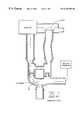
- FIG. 1is a side cross-sectional view of a ventilator system in accordance with a prior art device, showing the system during the inhalation phase;
- FIG. 2is a side cross-sectional view of an embodiment of the improved ventilator trigger device of the present invention showing the system during the exhalation phase;
- FIG. 3is a side cross-sectional view of an embodiment of the improved ventilator trigger device of the present invention.
- FIG. 4is a side cross-sectional view of the ventilator trigger device of FIG. 3 during the inhalation phase
- FIG. 5is a side cross-sectional view of the ventilator trigger device of FIG. 3 during the exhalation phase
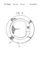
- FIG. 6is a top view of the exhalation check valve in its closed position.
- the present inventionis embodied in an improved method and apparatus for providing a patient triggered breath from a ventilator.
- the inventionresides in an improved connector in a patient/ventilator system that provides a chamber having a relatively small volume. This relatively small volume of the chamber provides the advantages over other ventilator trigger devices in that it permits a better rate and quality of gas exchange and provides a better sensitivity to pressure changes, thereby providing more accurate, earlier, and faster detection of the initiation of patient effort breathing.
- the present inventionincludes a connector 10 for connecting a patient's endo-tracheal tube 12 with a tube 14 emanating from the ventilator 16 itself and with a tube 18 that is in selective communication with the ambient atmosphere 20 .
- a connector 10for connecting a patient's endo-tracheal tube 12 with a tube 14 emanating from the ventilator 16 itself and with a tube 18 that is in selective communication with the ambient atmosphere 20 .
- the connector 10has a chamber 22 and has at least one wall 24 , which forms part of the chamber 22 .
- the chamber 22is defined by the wall or walls 24 of the connector 10 and by the bottom of the two-way check valve 26 , described below, and the plane that intersects the bottom edge of the connector 28 .
- the chamber 22 of the connector 10 of the present inventionpreferably has a volume of between about 1.0 to 1.3 cm 3 .
- the connector 10also has a first and second opening 30 and 32 , respectively, for the passage of gases.
- the openings 30 and 32may be cylindrical and sized to fit the openings of an endo-tracheal tube 12 and a patient wye tube 34 , as are well-known to those of ordinary skill in the art.
- the chamber 22 of the connector 10may be, but does not necessarily have to be, cylindrical in shape, although the chamber should be of such a shape so as to minimize the volume of space contained within the walls 24 of the chamber 22 and that are inexpensive and simple to manufacture.
- the walls 24 of the connector 10may be formed from any material strong enough to support connection to an endo-tracheal tube 12 and a patient wye tube 34 , and are preferably formed from a disposable, non-autoclavable material, such as ABS plastic. It is preferred that the material be disposable and non-autoclavable for safety reasons—so that each patient to use the ventilator be given their own connector to reduce the possibility of the transmission of germs or viruses that often are contained in the breath of patients who use ventilators and which sometimes may not be removed by the use of an autoclave. It is also preferred that the walls 24 of the connector 10 be transparent so that the interior of the chamber 22 can be viewed to determine whether there is any foreign matter contained within the chamber 22 that could block the passage of gasses through the chamber 22 .
- the connector of the present inventionis part of a larger gas flow circuit that connects a constant gas flow source—a ventilator 16 —to the patient's lungs, through an endo-tracheal tube 12 , and connects the exhalation of the patient to the ambient atmosphere 20 through an exhalation valve 36 .
- the systemis formed from tubes 14 and 18 , as is known in the art, the tubes being formed from any plastic or other material commonly used for such tubes.
- the endo-trachael tube 12is also any endo-tracheal tube, as is also well-known in the art.
- the ventilator 16provides an output of a constant flow of air, pure oxygen, or any other gas, or gas mixture, that is needed to be transmitted to the patient.
- the ventilatormay be an electro-pneumatic, continuous flow, time cycled, pressure-limited ventilator for infant, pediatric, and/or adult patients.
- the ventilatormay be adjusted in terms of numerous variables, including respiratory rate, inspiratory time, trigger sensitivity, inspiratory and expiratory pressure, waveform, FiO 2 , flow rate, etc. and may display these variables and data to the user or health care provider.
- the gases from the ventilator 16may also pass through a humidifier before entering the patient's lungs, if there is a need to add humidity to the gases.
- the ventilator 16preferably provides a constant flow of gas at a rate of between about 2 to 12 liters per minute, if the patient is an infant, or between 16 to 32 liters per minute if the patient is an adult.
- the ventilatorprovides a constant flow of gas at a pressure of 0 to 80 cm of water, which, when the exhalation valve 36 is open, is insufficient to overcome the cracking pressure of the inhalation check valve 38 , as discussed below.
- the connector 10may also have an opening 40 in a portion of its walls 24 for the attachment of a tube (not shown) which permits the gases of the chamber 22 to communicate with a pressure transducer 42 located at the other end of the tube.
- the pressure transducer 42is preferably any transducer that is capable of reading changes of pressure in the magnitude of as low as about 0.25 cm of water to 2 cm of water.
- the two-way check valve 26Located within the connector 10 is a two-way check valve 26 , which sits just above the chamber 22 .
- the two-way check valve 26comprises an inhalation check valve 38 and an exhalation check valve 44 .
- the inhalation check valve 38allows gas to pass from the ventilator 16 and through an opening between the valve 38 and the housing wall 50 in the inhalation check valve 38 , and to the patient's lungs. (See FIG. 4 ).
- the inhalation check valve 38is comprised of a plug 46 that is pressed against the interior 48 of the walls 50 of the connector 10 to form an airtight seal sealing the opening between the space above and below the plug 46 .
- the plugis pressed against the walls 50 of the connector 40 by the force of a spring 52 or other similar device.
- the plug 46is preferably formed from any type of plastic or similar material, including medical grade silicon, mylar, polyurethane, elastomers, and other similar polymers.
- the inhalation valve 38has a cracking pressure, i.e., the pressure necessary to overcome the force of the spring 52 and cause the plug 46 to be moved towards the spring 52 , of approximately 2 to 2.5 cm of water. (FIG. 4)
- a cracking pressurei.e., the pressure necessary to overcome the force of the spring 52 and cause the plug 46 to be moved towards the spring 52 .
- the walls 50 of the connector 10are shaped so that, when the plug 46 of the inhalation valve 38 is moved towards the spring 52 the edges of the plug 46 no longer contact the wall 50 of the connector 10 , an opening 54 is formed through which gas can flow from the ventilator 16 , past the inhalation check valve 38 , through the chamber 22 , through the endo-trachael tube 12 and into the patient's lungs.
- the exhalation check valve 44allows gas to pass from the patient's lungs, through the exhalation check valve 44 , and to the ventilator 16 . (See FIGS. 5 and 6 ).
- the exhalation check valve 44is located over an opening 56 formed in the center of the plug 46 of the inhalation valve 38 .
- the exhalation check valve 44is preferably formed from a piece of medical grade silicone, mylar, polyurethane, elastomers, or other similar polymer, that is shaped with an outer portion of a ring 58 attached to a substantially circular flap 60 .
- the outer portionpreferably lies entirely on top of the plug 46 of the of the inhalation check valve 38 , whereas only the outer edge 62 of the substantially circular flap 60 lies over the plug 46 , with the remainder of the inner portion of the flap 60 covering the opening 56 of the plug 46 .
- the exhalation check valve 44is maintained in its position on the surface of the plug 46 of the inhalation check valve 38 by the use of a retainer ring 64 that fits over the outer ring portion 58 of the exhalation check valve and, under a portion of the plug 46 .
- the exhalation check valve 44has a cracking pressure, i.e., the pressure necessary to overcome the force necessary to lift the flap 60 and expose a portion of the opening 56 of the plug 46 of approximately 2 to 2.5 cm of water. (See FIGS. 5 and 6 ).
- a cracking pressurei.e., the pressure necessary to overcome the force necessary to lift the flap 60 and expose a portion of the opening 56 of the plug 46 of approximately 2 to 2.5 cm of water.
- the present inventionprovides the benefits of being able to detect the initiation of the patient effort breath quickly—within the first 0.25 to 2 cm of water change in pressure in the chamber 22 of the connector 10 , which is within the first 1 to 1.5 cm 3 of change in volume of the patient's lungs.
- the detection of the initiation of the patient effort breathprovides the benefit that the ventilator 16 can more accurately and quickly provide the patient with the patient triggered breath from the ventilator. Further, such early detection prevents the patient from having to exert too great an effort to initiate a breath prior to the initiation of the patient triggered breath. With such a reduction in effort by the patient, the patient's energy can be used more appropriately for the healing of the patient's ailments.
- the present inventiondetects the initiation of the patient breath and provides the patient triggered breath as follows. Assuming that the patient has just completed her exhalation phase of a prior breath, and is about to begin the inhalation phase of her breath, the state of the system is such that both the inhalation and exhalation check valves 38 and 44 , are closed and the area within the chamber 10 , endo-trachael tube 12 , and the patient's lungs is finite. (See FIG. 3 ). The gas flow from the ventilator 12 travels over the two-way check valve 26 , through the patient wye 34 , and out to the ambient atmosphere 20 through the open exhalation valve 36 .
- the volume of the patient's lungsbegins to increase.
- This increase in volume of the lungscauses an increase in the overall volume of the chamber 22 /endo-trachael tube 12 /lungs and thereby causing a reduction in the pressure of the gas within the chamber area. (See FIG. 4 ).
- This reduction in pressurecan be detected by the pressure transducer 42 .
- the pressure transducer 42is connected to a microprocessor having analog and digital filters, as is known in the art, for filtering out the noise of the gas system and the electronics.
- the microprocessoris looking for a reduction in the pressure of 0.25 to 2 cm of water within the chamber, with the assumption that there is approximately 0.1 cm of water of noise within the system.
- the microprocessoris pre-programmed to assume that a reduction in pressure in the chamber, as measured by the pressure transducer, and after filtering, is a sign that the patient has initiated a patient effort breath.
- the exhalation valve 36is any valve that can be opened and shut with an electric signal.
- the exhalation valve 36opens to the ambient atmosphere 20 and permits the gases flowing within the system to be removed from the system and into the ambient atmosphere.
- the closing of the exhalation valve 36causes the gases flowing within the system to stay within the system and not bleed out into the ambient atmosphere 20 through the exhalation valve 36 .
- the pressure with the ventilator tubes 14 and 18increases.
- the cracking pressure of the inhalation check valve 38is surpassed and the inhalation check valve 38 is caused to open, thereby permitting the flow of the fresh gases from the ventilator 16 to flow through the inhalation check valve 38 , into the chamber 22 , through the endo-tracheal tube 12 and into the lungs of the patient. (See FIG. 4 ).
- the quick and early detection of the initiation of the patient effort breathallows the flow of the gas from the ventilator to occur at a time just after the patient has initiated the patient effort breath.
- the early detection of the initiation of the patient effort breath and quick opening of the inhalation check valve 38permit the fresh ventilator gas to be introduced to the lungs of the patient within such a short amount of time that the patient can accurately and assuredly be provided with patient triggered breaths that are properly synchronized with the patient effort breath.
- the ventilator 16is set to a predetermined time for the gas to flow to the patient's lungs.
- one of the variables that can be adjusted on the ventilatoris the inspiratory time.
- the exhalation valve 36will remain closed and the gases flowing from the ventilator 16 will pass through the inhalation check valve 38 and into the lungs of the patient. (See FIG. 4 ).
- the inspiratory timeis preferably between approximately 0.1 to 3.0 seconds.
- the exhalation valve 36is re-opened, thereby allowing the gas flowing from the ventilator 16 to flow out of the system through the exhalation valve 36 and into the ambient atmosphere 20 .
- the pressure at the inhalation check valve 38is reduced to an amount that is less than the cracking pressure of the inhalation check valve 38 , thereby causing the inhalation check valve 38 to close.
- This reduction of the pressure at the inhalation check valve 38also causes a reduction in the pressure within the patient's lungs. This reduction of pressure permits the patient's lungs to compress to their resting state. As the patient's lungs compress, the lungs exhale the gas from within.
- the exhaling gas from the lungscauses an increase in the pressure within the chamber of an amount that is greater than the cracking pressure of the exhalation check valve 44 , thereby opening the exhalation check valve 44 and permitting the exhalation gas from the patient's lungs to pass into the patient wye tube 34 and out to the ambient atmosphere 20 through the opened exhalation valve 36 . (See FIG. 2 ).
- the pressure within the chamber 22is again reduced and the exhalation check valve 44 can close. The process then starts over again when the patient begins to make a patient assist breath and the pressure within the chamber is again reduced.
- the chamber of the present inventioncan be between about 1.0 to 1.3 cm 3 , which represents a reduction in the volume of this chamber of one-tenth over the MIT ventilator trigger device. (See FIG. 1 ). This one-tenth reduction in the volume of the chamber 22 provides the benefit that the change in pressure can be detected ten times faster in the device of the present invention than in the MIT device. (FIG. 1 ).
- the rate and quality of the gas exchange in the device of the present inventionis significantly improved over that of the MIT device. (FIG. 1 ).
- the amount of exhaled gases that could possibly be returned to the patient during their next breathi.e., the rate of gas exchange in the patient, is at most between about 1.0 to 1.3 cm 3 plus the volume of the endo-trachael tube 12 , which is even less.
- the volume of the chamber 66is about 10 cm 3 , and thus in the MIT device, the amount of exhaled gases that could possibly be returned to the patient during their next breath can be as much as 10 cm 3 . (FIG. 1 ).
- the amount of exhaled gases that could possibly be returned to the patient during their next breathcan be as much as 10 cm 3 . (FIG. 1 ).
- inhalation and exhalation check valves 38 and 44do not have to have the plug 46 and spring 52 and flap 60 configurations described above. Rather, they need only be any type of valve that is capable of maintaining a cracking pressure of between 2.0 to 2.5 cm of water and that are small enough so as to provide a chamber of a small enough volume to provide the benefits described herein. Accordingly, it is not intended that the invention be limited by the specific embodiment disclosed in the drawings and described in detail herein above.
Landscapes
- Health & Medical Sciences (AREA)
- Pulmonology (AREA)
- Heart & Thoracic Surgery (AREA)
- Engineering & Computer Science (AREA)
- Anesthesiology (AREA)
- Biomedical Technology (AREA)
- Emergency Medicine (AREA)
- Hematology (AREA)
- Life Sciences & Earth Sciences (AREA)
- Animal Behavior & Ethology (AREA)
- General Health & Medical Sciences (AREA)
- Public Health (AREA)
- Veterinary Medicine (AREA)
- Measurement Of The Respiration, Hearing Ability, Form, And Blood Characteristics Of Living Organisms (AREA)
- Percussion Or Vibration Massage (AREA)
Abstract
Description
Claims (18)
Priority Applications (3)
| Application Number | Priority Date | Filing Date | Title |
|---|---|---|---|
| US09/183,761US6230708B1 (en) | 1998-10-30 | 1998-10-30 | Ventilator triggering device |
| BR9905344-6ABR9905344A (en) | 1998-10-30 | 1999-10-29 | Enhanced fan trigger device |
| JP11310674AJP2000152993A (en) | 1998-10-30 | 1999-11-01 | Improved artificial respirator starter |
Applications Claiming Priority (1)
| Application Number | Priority Date | Filing Date | Title |
|---|---|---|---|
| US09/183,761US6230708B1 (en) | 1998-10-30 | 1998-10-30 | Ventilator triggering device |
Publications (1)
| Publication Number | Publication Date |
|---|---|
| US6230708B1true US6230708B1 (en) | 2001-05-15 |
Family
ID=22674178
Family Applications (1)
| Application Number | Title | Priority Date | Filing Date |
|---|---|---|---|
| US09/183,761Expired - Fee RelatedUS6230708B1 (en) | 1998-10-30 | 1998-10-30 | Ventilator triggering device |
Country Status (3)
| Country | Link |
|---|---|
| US (1) | US6230708B1 (en) |
| JP (1) | JP2000152993A (en) |
| BR (1) | BR9905344A (en) |
Cited By (52)
| Publication number | Priority date | Publication date | Assignee | Title |
|---|---|---|---|---|
| US6446629B1 (en)* | 1998-07-31 | 2002-09-10 | Suzuki Motor Corporation | Artificial respiration apparatus |
| US20030050568A1 (en)* | 2001-05-23 | 2003-03-13 | Green Paul Anthony | Ventilator patient synchronization |
| US6739334B2 (en)* | 2001-03-07 | 2004-05-25 | Maquet Critical Care Ab | Expiration cassette that is removably insertable in the expiration section of a ventilation |
| US20060149144A1 (en)* | 1997-01-27 | 2006-07-06 | Lynn Lawrence A | System and method for automatic detection of a plurality of SPO2 time series pattern types |
| US20060155206A1 (en)* | 1997-01-27 | 2006-07-13 | Lynn Lawrence A | System and method for sound and oximetry integration |
| US20060161071A1 (en)* | 1997-01-27 | 2006-07-20 | Lynn Lawrence A | Time series objectification system and method |
| US20060201504A1 (en)* | 2005-03-08 | 2006-09-14 | Singhal Aneesh B | High-flow oxygen delivery system and methods of use thereof |
| US20080029094A1 (en)* | 2006-08-03 | 2008-02-07 | Fuhrman Bradley P | Gas Delivery System And Method |
| US20080060646A1 (en)* | 2006-09-11 | 2008-03-13 | Fernando Isaza | Ventilating apparatus and method enabling a patient to talk with or without a trachostomy tube check valve |
| WO2008033730A3 (en)* | 2006-09-11 | 2008-05-08 | Ric Investments Llc | Detecting ventilator system anomalies while in a speaking mode |
| CN100446826C (en)* | 2005-02-07 | 2008-12-31 | 中国人民解放军军事医学科学院卫生装备研究所 | Multi-path medical oxygen supplying system |
| US20090050153A1 (en)* | 2005-12-16 | 2009-02-26 | Hamilton Medical Ag | Tube system for ventilation appliances |
| GB2459305A (en)* | 2008-04-18 | 2009-10-21 | Laerdal Medical As | A ventilation device and a method for operating a ventilation device |
| US20100071695A1 (en)* | 2008-09-23 | 2010-03-25 | Ron Thiessen | Patient wye with flow transducer |
| US20100288283A1 (en)* | 2009-05-15 | 2010-11-18 | Nellcor Puritan Bennett Llc | Dynamic adjustment of tube compensation factor based on internal changes in breathing tube |
| US20100314469A1 (en)* | 2007-05-08 | 2010-12-16 | Thomas Roschke | Combined ventilator/gas valve unit |
| WO2011017763A1 (en)* | 2009-08-11 | 2011-02-17 | Resmed Motor Technologies Inc. | Single stage, axial symmetric blower and portable ventilator |
| CN102165237A (en)* | 2008-04-30 | 2011-08-24 | 丹佛斯多能公司 | A power actuated valve |
| US20120255553A1 (en)* | 2000-03-13 | 2012-10-11 | Innomed Technologies Inc. | Ventilation interface for sleep apnea therapy |
| US8424520B2 (en) | 2008-09-23 | 2013-04-23 | Covidien Lp | Safe standby mode for ventilator |
| US8485185B2 (en) | 2008-06-06 | 2013-07-16 | Covidien Lp | Systems and methods for ventilation in proportion to patient effort |
| US8666467B2 (en) | 2001-05-17 | 2014-03-04 | Lawrence A. Lynn | System and method for SPO2 instability detection and quantification |
| US8714154B2 (en) | 2011-03-30 | 2014-05-06 | Covidien Lp | Systems and methods for automatic adjustment of ventilator settings |
| US20140128761A1 (en)* | 2004-12-08 | 2014-05-08 | Benjamin K. CLINE | Passive nasal peep devices |
| US8728001B2 (en) | 2006-02-10 | 2014-05-20 | Lawrence A. Lynn | Nasal capnographic pressure monitoring system |
| US8783250B2 (en) | 2011-02-27 | 2014-07-22 | Covidien Lp | Methods and systems for transitory ventilation support |
| US8844526B2 (en) | 2012-03-30 | 2014-09-30 | Covidien Lp | Methods and systems for triggering with unknown base flow |
| US9031793B2 (en) | 2001-05-17 | 2015-05-12 | Lawrence A. Lynn | Centralized hospital monitoring system for automatically detecting upper airway instability and for preventing and aborting adverse drug reactions |
| US9053222B2 (en) | 2002-05-17 | 2015-06-09 | Lawrence A. Lynn | Patient safety processor |
| US20150231359A1 (en)* | 2012-09-07 | 2015-08-20 | Intersurgical Ag | Valve assemblies |
| US9327089B2 (en) | 2012-03-30 | 2016-05-03 | Covidien Lp | Methods and systems for compensation of tubing related loss effects |
| US9364624B2 (en) | 2011-12-07 | 2016-06-14 | Covidien Lp | Methods and systems for adaptive base flow |
| US9498589B2 (en) | 2011-12-31 | 2016-11-22 | Covidien Lp | Methods and systems for adaptive base flow and leak compensation |
| US9521971B2 (en) | 1997-07-14 | 2016-12-20 | Lawrence A. Lynn | System and method for automatic detection of a plurality of SPO2 time series pattern types |
| US9649458B2 (en) | 2008-09-30 | 2017-05-16 | Covidien Lp | Breathing assistance system with multiple pressure sensors |
| US9808591B2 (en) | 2014-08-15 | 2017-11-07 | Covidien Lp | Methods and systems for breath delivery synchronization |
| CN107441605A (en)* | 2017-08-28 | 2017-12-08 | 王侨 | With the breather valve and its control method on lung ventilator |
| US9925346B2 (en) | 2015-01-20 | 2018-03-27 | Covidien Lp | Systems and methods for ventilation with unknown exhalation flow |
| US9950129B2 (en) | 2014-10-27 | 2018-04-24 | Covidien Lp | Ventilation triggering using change-point detection |
| US9981096B2 (en) | 2013-03-13 | 2018-05-29 | Covidien Lp | Methods and systems for triggering with unknown inspiratory flow |
| US10354753B2 (en) | 2001-05-17 | 2019-07-16 | Lawrence A. Lynn | Medical failure pattern search engine |
| US10362967B2 (en) | 2012-07-09 | 2019-07-30 | Covidien Lp | Systems and methods for missed breath detection and indication |
| CN111407995A (en)* | 2020-04-03 | 2020-07-14 | 北京大学人民医院 | A ventilator and its dedicated ventilation loop connection device and assembly method |
| US10857317B2 (en)* | 2015-12-04 | 2020-12-08 | Trudell Medical International | Huff cough simulation device |
| US11324954B2 (en) | 2019-06-28 | 2022-05-10 | Covidien Lp | Achieving smooth breathing by modified bilateral phrenic nerve pacing |
| US11383061B2 (en)* | 2016-10-24 | 2022-07-12 | Hamilton Medical Ag | Exhalation valve for a ventilator apparatus with a valve configuration for reducing noise emission |
| US20220218927A1 (en)* | 2021-01-08 | 2022-07-14 | Airmid Critical Care Products, Inc. | Data-integrated artificial ventilation system |
| US20220288347A1 (en)* | 2019-08-16 | 2022-09-15 | Korea University Research And Business Foundation | Bidirectional Flow-Controllable Artificial Respirator |
| US11478594B2 (en) | 2018-05-14 | 2022-10-25 | Covidien Lp | Systems and methods for respiratory effort detection utilizing signal distortion |
| CN115400307A (en)* | 2022-08-23 | 2022-11-29 | 西安医学院第二附属医院 | Breathing machine convenient to respirator changes |
| US11752287B2 (en) | 2018-10-03 | 2023-09-12 | Covidien Lp | Systems and methods for automatic cycling or cycling detection |
| US12257437B2 (en) | 2020-09-30 | 2025-03-25 | Covidien Lp | Intravenous phrenic nerve stimulation lead |
Citations (10)
| Publication number | Priority date | Publication date | Assignee | Title |
|---|---|---|---|---|
| US4538607A (en)* | 1984-02-06 | 1985-09-03 | Ab Fixfabriken | Tracheostomy valve |
| US4582058A (en)* | 1984-11-26 | 1986-04-15 | Bivona, Inc. | Tracheostoma valves |
| US5042473A (en)* | 1990-02-15 | 1991-08-27 | Pro-Tech Respirators, Inc. | Demand valve for a respirator |
| US5059208A (en)* | 1991-02-04 | 1991-10-22 | Helix Medical, Inc. | Adjustable tracheostoma valve |
| US5390666A (en) | 1990-05-11 | 1995-02-21 | Puritan-Bennett Corporation | System and method for flow triggering of breath supported ventilation |
| US5501214A (en)* | 1994-09-26 | 1996-03-26 | Respironics, Inc. | Non-rebreathing valve and valve element therefor |
| US5513631A (en) | 1995-07-21 | 1996-05-07 | Infrasonics, Inc. | Triggering of patient ventilator responsive to a precursor signal |
| US5542415A (en) | 1991-05-07 | 1996-08-06 | Infrasonics, Inc. | Apparatus and process for controlling the ventilation of the lungs of a patient |
| US5542447A (en)* | 1994-01-18 | 1996-08-06 | Normalair-Garrett (Holdings) Limited | Aircrew breathing systems |
| US5660171A (en) | 1990-05-11 | 1997-08-26 | Puritan-Bennett Corporation | System and method for flow triggering of pressure supported ventilation by comparison of inhalation and exhalation flow rates |
- 1998
- 1998-10-30USUS09/183,761patent/US6230708B1/ennot_activeExpired - Fee Related
- 1999
- 1999-10-29BRBR9905344-6Apatent/BR9905344A/ennot_activeApplication Discontinuation
- 1999-11-01JPJP11310674Apatent/JP2000152993A/enactivePending
Patent Citations (10)
| Publication number | Priority date | Publication date | Assignee | Title |
|---|---|---|---|---|
| US4538607A (en)* | 1984-02-06 | 1985-09-03 | Ab Fixfabriken | Tracheostomy valve |
| US4582058A (en)* | 1984-11-26 | 1986-04-15 | Bivona, Inc. | Tracheostoma valves |
| US5042473A (en)* | 1990-02-15 | 1991-08-27 | Pro-Tech Respirators, Inc. | Demand valve for a respirator |
| US5390666A (en) | 1990-05-11 | 1995-02-21 | Puritan-Bennett Corporation | System and method for flow triggering of breath supported ventilation |
| US5660171A (en) | 1990-05-11 | 1997-08-26 | Puritan-Bennett Corporation | System and method for flow triggering of pressure supported ventilation by comparison of inhalation and exhalation flow rates |
| US5059208A (en)* | 1991-02-04 | 1991-10-22 | Helix Medical, Inc. | Adjustable tracheostoma valve |
| US5542415A (en) | 1991-05-07 | 1996-08-06 | Infrasonics, Inc. | Apparatus and process for controlling the ventilation of the lungs of a patient |
| US5542447A (en)* | 1994-01-18 | 1996-08-06 | Normalair-Garrett (Holdings) Limited | Aircrew breathing systems |
| US5501214A (en)* | 1994-09-26 | 1996-03-26 | Respironics, Inc. | Non-rebreathing valve and valve element therefor |
| US5513631A (en) | 1995-07-21 | 1996-05-07 | Infrasonics, Inc. | Triggering of patient ventilator responsive to a precursor signal |
Cited By (115)
| Publication number | Priority date | Publication date | Assignee | Title |
|---|---|---|---|---|
| US20060161071A1 (en)* | 1997-01-27 | 2006-07-20 | Lynn Lawrence A | Time series objectification system and method |
| US9468378B2 (en) | 1997-01-27 | 2016-10-18 | Lawrence A. Lynn | Airway instability detection system and method |
| US20060149144A1 (en)* | 1997-01-27 | 2006-07-06 | Lynn Lawrence A | System and method for automatic detection of a plurality of SPO2 time series pattern types |
| US20060155206A1 (en)* | 1997-01-27 | 2006-07-13 | Lynn Lawrence A | System and method for sound and oximetry integration |
| US9042952B2 (en) | 1997-01-27 | 2015-05-26 | Lawrence A. Lynn | System and method for automatic detection of a plurality of SPO2 time series pattern types |
| US9521971B2 (en) | 1997-07-14 | 2016-12-20 | Lawrence A. Lynn | System and method for automatic detection of a plurality of SPO2 time series pattern types |
| US6446629B1 (en)* | 1998-07-31 | 2002-09-10 | Suzuki Motor Corporation | Artificial respiration apparatus |
| US9919121B2 (en) | 2000-03-13 | 2018-03-20 | Innomed Healthscience, Inc. | Ventilation interface for sleep apnea therapy |
| US20120255553A1 (en)* | 2000-03-13 | 2012-10-11 | Innomed Technologies Inc. | Ventilation interface for sleep apnea therapy |
| US9138553B2 (en)* | 2000-03-13 | 2015-09-22 | Innomed Technologies, Inc. | Ventilation interface for sleep apnea therapy |
| US10058269B2 (en) | 2000-07-28 | 2018-08-28 | Lawrence A. Lynn | Monitoring system for identifying an end-exhalation carbon dioxide value of enhanced clinical utility |
| US8932227B2 (en) | 2000-07-28 | 2015-01-13 | Lawrence A. Lynn | System and method for CO2 and oximetry integration |
| US6739334B2 (en)* | 2001-03-07 | 2004-05-25 | Maquet Critical Care Ab | Expiration cassette that is removably insertable in the expiration section of a ventilation |
| US10366790B2 (en) | 2001-05-17 | 2019-07-30 | Lawrence A. Lynn | Patient safety processor |
| US10354753B2 (en) | 2001-05-17 | 2019-07-16 | Lawrence A. Lynn | Medical failure pattern search engine |
| US9031793B2 (en) | 2001-05-17 | 2015-05-12 | Lawrence A. Lynn | Centralized hospital monitoring system for automatically detecting upper airway instability and for preventing and aborting adverse drug reactions |
| US8862196B2 (en) | 2001-05-17 | 2014-10-14 | Lawrence A. Lynn | System and method for automatic detection of a plurality of SP02 time series pattern types |
| US10032526B2 (en) | 2001-05-17 | 2018-07-24 | Lawrence A. Lynn | Patient safety processor |
| US8666467B2 (en) | 2001-05-17 | 2014-03-04 | Lawrence A. Lynn | System and method for SPO2 instability detection and quantification |
| US10297348B2 (en) | 2001-05-17 | 2019-05-21 | Lawrence A. Lynn | Patient safety processor |
| US11439321B2 (en) | 2001-05-17 | 2022-09-13 | Lawrence A. Lynn | Monitoring system for identifying an end-exhalation carbon dioxide value of enhanced clinical utility |
| US6997881B2 (en)* | 2001-05-23 | 2006-02-14 | Resmed Limited | Ventilator patient synchronization |
| US20050143672A1 (en)* | 2001-05-23 | 2005-06-30 | Green Paul A. | Ventilator patient synchronization |
| US20100236556A1 (en)* | 2001-05-23 | 2010-09-23 | Paul Anthony Green | Ventilator patient synchronization |
| US7727160B2 (en) | 2001-05-23 | 2010-06-01 | Resmed Limited | Ventilator patient synchronization |
| US6860858B2 (en)* | 2001-05-23 | 2005-03-01 | Resmed Limited | Ventilator patient synchronization |
| US20030050568A1 (en)* | 2001-05-23 | 2003-03-13 | Green Paul Anthony | Ventilator patient synchronization |
| US7914459B2 (en) | 2001-05-23 | 2011-03-29 | Resmed Limited | Ventilator patient synchronization |
| US20110139156A1 (en)* | 2001-05-23 | 2011-06-16 | Paul Anthony Green | Ventilator patient synchronization |
| US20060079799A1 (en)* | 2001-05-23 | 2006-04-13 | Green Paul A | Ventilator patient synchronization |
| US8388548B2 (en) | 2001-05-23 | 2013-03-05 | Resmed Limited | Ventilator patient synchronization |
| US9053222B2 (en) | 2002-05-17 | 2015-06-09 | Lawrence A. Lynn | Patient safety processor |
| US20160361067A9 (en)* | 2004-12-08 | 2016-12-15 | Theravent, Inc. | Passive nasal peep devices |
| US20140128761A1 (en)* | 2004-12-08 | 2014-05-08 | Benjamin K. CLINE | Passive nasal peep devices |
| US10610228B2 (en)* | 2004-12-08 | 2020-04-07 | Theravent, Inc. | Passive nasal peep devices |
| CN100446826C (en)* | 2005-02-07 | 2008-12-31 | 中国人民解放军军事医学科学院卫生装备研究所 | Multi-path medical oxygen supplying system |
| US20060201504A1 (en)* | 2005-03-08 | 2006-09-14 | Singhal Aneesh B | High-flow oxygen delivery system and methods of use thereof |
| US20090050153A1 (en)* | 2005-12-16 | 2009-02-26 | Hamilton Medical Ag | Tube system for ventilation appliances |
| US8181649B2 (en)* | 2005-12-16 | 2012-05-22 | Hamilton Medical Ag | Tube system for ventilation appliances |
| US8728001B2 (en) | 2006-02-10 | 2014-05-20 | Lawrence A. Lynn | Nasal capnographic pressure monitoring system |
| US20080029094A1 (en)* | 2006-08-03 | 2008-02-07 | Fuhrman Bradley P | Gas Delivery System And Method |
| WO2008017065A3 (en)* | 2006-08-03 | 2008-09-04 | Univ New York State Res Found | Gas delivery system and method |
| US7533669B2 (en)* | 2006-08-03 | 2009-05-19 | The Research Foundation Of State University Of New York | Gas delivery system and method |
| US20110259339A1 (en)* | 2006-09-11 | 2011-10-27 | Ric Investments, Llc | Ventilating apparatus and method enabling a patient to talk with or without a trachostomy tube check valve |
| EP2066412A4 (en)* | 2006-09-11 | 2014-11-05 | Ric Investments Llc | VENTILATION SYSTEM ANOMALY DETECTION IN SPEECH MODE |
| CN101553284B (en)* | 2006-09-11 | 2013-07-31 | Ric投资有限责任公司 | Detecting ventilator system anomalies while in a speaking mode |
| US20080060656A1 (en)* | 2006-09-11 | 2008-03-13 | Ric Investments, Llc | Detecting ventilator system anomalies while in a speaking mode |
| WO2008033730A3 (en)* | 2006-09-11 | 2008-05-08 | Ric Investments Llc | Detecting ventilator system anomalies while in a speaking mode |
| RU2455030C2 (en)* | 2006-09-11 | 2012-07-10 | РИК ИНВЕСТМЕНТС, ЭлЭлСи | Talk-mode deviation detection in artificial pulmonary ventilation system |
| US7997272B2 (en) | 2006-09-11 | 2011-08-16 | Ric Investments, Llc. | Ventilating apparatus and method enabling a patient to talk with or without a trachostomy tube check valve |
| US20080060646A1 (en)* | 2006-09-11 | 2008-03-13 | Fernando Isaza | Ventilating apparatus and method enabling a patient to talk with or without a trachostomy tube check valve |
| US8161972B2 (en) | 2006-09-11 | 2012-04-24 | Ric Investments, Llc | Detecting ventilator system anomalies while in a speaking mode |
| EP2066384A4 (en)* | 2006-09-11 | 2014-11-05 | Ric Investments Llc | VENTILATION APPARATUS AND METHOD FOR PATIENT TO SPEAK WITH OR WITHOUT TRACHEOSTOMY TUBE ANCHOR RETURN VALVE |
| US20100314469A1 (en)* | 2007-05-08 | 2010-12-16 | Thomas Roschke | Combined ventilator/gas valve unit |
| GB2459305B (en)* | 2008-04-18 | 2010-06-16 | Laerdal Medical As | The invention regards a ventilation device and a method for operating the ventilation device. |
| US8875708B2 (en) | 2008-04-18 | 2014-11-04 | Laerdal Medical As | Ventilation device and method for CPR |
| GB2459305A (en)* | 2008-04-18 | 2009-10-21 | Laerdal Medical As | A ventilation device and a method for operating a ventilation device |
| CN102165237A (en)* | 2008-04-30 | 2011-08-24 | 丹佛斯多能公司 | A power actuated valve |
| US8485183B2 (en) | 2008-06-06 | 2013-07-16 | Covidien Lp | Systems and methods for triggering and cycling a ventilator based on reconstructed patient effort signal |
| US8826907B2 (en) | 2008-06-06 | 2014-09-09 | Covidien Lp | Systems and methods for determining patient effort and/or respiratory parameters in a ventilation system |
| US9126001B2 (en) | 2008-06-06 | 2015-09-08 | Covidien Lp | Systems and methods for ventilation in proportion to patient effort |
| US8485185B2 (en) | 2008-06-06 | 2013-07-16 | Covidien Lp | Systems and methods for ventilation in proportion to patient effort |
| US9956363B2 (en) | 2008-06-06 | 2018-05-01 | Covidien Lp | Systems and methods for triggering and cycling a ventilator based on reconstructed patient effort signal |
| US9925345B2 (en) | 2008-06-06 | 2018-03-27 | Covidien Lp | Systems and methods for determining patient effort and/or respiratory parameters in a ventilation system |
| US8485184B2 (en) | 2008-06-06 | 2013-07-16 | Covidien Lp | Systems and methods for monitoring and displaying respiratory information |
| US9114220B2 (en) | 2008-06-06 | 2015-08-25 | Covidien Lp | Systems and methods for triggering and cycling a ventilator based on reconstructed patient effort signal |
| US10828437B2 (en) | 2008-06-06 | 2020-11-10 | Covidien Lp | Systems and methods for triggering and cycling a ventilator based on reconstructed patient effort signal |
| US8424520B2 (en) | 2008-09-23 | 2013-04-23 | Covidien Lp | Safe standby mode for ventilator |
| US10493225B2 (en) | 2008-09-23 | 2019-12-03 | Covidien Lp | Safe standby mode for ventilator |
| US11344689B2 (en) | 2008-09-23 | 2022-05-31 | Covidien Lp | Safe standby mode for ventilator |
| US9381314B2 (en) | 2008-09-23 | 2016-07-05 | Covidien Lp | Safe standby mode for ventilator |
| US20100071695A1 (en)* | 2008-09-23 | 2010-03-25 | Ron Thiessen | Patient wye with flow transducer |
| US9649458B2 (en) | 2008-09-30 | 2017-05-16 | Covidien Lp | Breathing assistance system with multiple pressure sensors |
| US20100288283A1 (en)* | 2009-05-15 | 2010-11-18 | Nellcor Puritan Bennett Llc | Dynamic adjustment of tube compensation factor based on internal changes in breathing tube |
| US10874810B2 (en) | 2009-08-11 | 2020-12-29 | Resmed Motor Technologies Inc. | Single stage, axial symmetric blower and portable ventilator |
| US9861774B2 (en) | 2009-08-11 | 2018-01-09 | Resmed Motor Technologies Inc. | Single stage, axial symmetric blower and portable ventilator |
| WO2011017763A1 (en)* | 2009-08-11 | 2011-02-17 | Resmed Motor Technologies Inc. | Single stage, axial symmetric blower and portable ventilator |
| US11998690B2 (en) | 2009-08-11 | 2024-06-04 | Resmed Motor Technologies Inc. | Single stage, axial symmetric blower and portable ventilator |
| US8783250B2 (en) | 2011-02-27 | 2014-07-22 | Covidien Lp | Methods and systems for transitory ventilation support |
| US8714154B2 (en) | 2011-03-30 | 2014-05-06 | Covidien Lp | Systems and methods for automatic adjustment of ventilator settings |
| US10543327B2 (en) | 2011-12-07 | 2020-01-28 | Covidien Lp | Methods and systems for adaptive base flow |
| US11497869B2 (en) | 2011-12-07 | 2022-11-15 | Covidien Lp | Methods and systems for adaptive base flow |
| US9364624B2 (en) | 2011-12-07 | 2016-06-14 | Covidien Lp | Methods and systems for adaptive base flow |
| US10709854B2 (en) | 2011-12-31 | 2020-07-14 | Covidien Lp | Methods and systems for adaptive base flow and leak compensation |
| US11833297B2 (en) | 2011-12-31 | 2023-12-05 | Covidien Lp | Methods and systems for adaptive base flow and leak compensation |
| US9498589B2 (en) | 2011-12-31 | 2016-11-22 | Covidien Lp | Methods and systems for adaptive base flow and leak compensation |
| US20140360497A1 (en)* | 2012-03-30 | 2014-12-11 | Covidien Lp | Methods and systems for triggering with unknown base flow |
| US10029057B2 (en)* | 2012-03-30 | 2018-07-24 | Covidien Lp | Methods and systems for triggering with unknown base flow |
| US9327089B2 (en) | 2012-03-30 | 2016-05-03 | Covidien Lp | Methods and systems for compensation of tubing related loss effects |
| US8844526B2 (en) | 2012-03-30 | 2014-09-30 | Covidien Lp | Methods and systems for triggering with unknown base flow |
| US11642042B2 (en) | 2012-07-09 | 2023-05-09 | Covidien Lp | Systems and methods for missed breath detection and indication |
| US10362967B2 (en) | 2012-07-09 | 2019-07-30 | Covidien Lp | Systems and methods for missed breath detection and indication |
| US20150231359A1 (en)* | 2012-09-07 | 2015-08-20 | Intersurgical Ag | Valve assemblies |
| US10589054B2 (en)* | 2012-09-07 | 2020-03-17 | Intersurgical Ag | Valve assemblies |
| US9981096B2 (en) | 2013-03-13 | 2018-05-29 | Covidien Lp | Methods and systems for triggering with unknown inspiratory flow |
| US10864336B2 (en) | 2014-08-15 | 2020-12-15 | Covidien Lp | Methods and systems for breath delivery synchronization |
| US9808591B2 (en) | 2014-08-15 | 2017-11-07 | Covidien Lp | Methods and systems for breath delivery synchronization |
| US11712174B2 (en) | 2014-10-27 | 2023-08-01 | Covidien Lp | Ventilation triggering |
| US10940281B2 (en) | 2014-10-27 | 2021-03-09 | Covidien Lp | Ventilation triggering |
| US9950129B2 (en) | 2014-10-27 | 2018-04-24 | Covidien Lp | Ventilation triggering using change-point detection |
| US9925346B2 (en) | 2015-01-20 | 2018-03-27 | Covidien Lp | Systems and methods for ventilation with unknown exhalation flow |
| US10857317B2 (en)* | 2015-12-04 | 2020-12-08 | Trudell Medical International | Huff cough simulation device |
| US11964103B2 (en) | 2015-12-04 | 2024-04-23 | Trudell Medical International | Huff Cough simulation device |
| US11383061B2 (en)* | 2016-10-24 | 2022-07-12 | Hamilton Medical Ag | Exhalation valve for a ventilator apparatus with a valve configuration for reducing noise emission |
| CN107441605A (en)* | 2017-08-28 | 2017-12-08 | 王侨 | With the breather valve and its control method on lung ventilator |
| US11478594B2 (en) | 2018-05-14 | 2022-10-25 | Covidien Lp | Systems and methods for respiratory effort detection utilizing signal distortion |
| US11752287B2 (en) | 2018-10-03 | 2023-09-12 | Covidien Lp | Systems and methods for automatic cycling or cycling detection |
| US11324954B2 (en) | 2019-06-28 | 2022-05-10 | Covidien Lp | Achieving smooth breathing by modified bilateral phrenic nerve pacing |
| US12036409B2 (en) | 2019-06-28 | 2024-07-16 | Covidien Lp | Achieving smooth breathing by modified bilateral phrenic nerve pacing |
| US20220288347A1 (en)* | 2019-08-16 | 2022-09-15 | Korea University Research And Business Foundation | Bidirectional Flow-Controllable Artificial Respirator |
| CN111407995A (en)* | 2020-04-03 | 2020-07-14 | 北京大学人民医院 | A ventilator and its dedicated ventilation loop connection device and assembly method |
| US12257437B2 (en) | 2020-09-30 | 2025-03-25 | Covidien Lp | Intravenous phrenic nerve stimulation lead |
| US20220218927A1 (en)* | 2021-01-08 | 2022-07-14 | Airmid Critical Care Products, Inc. | Data-integrated artificial ventilation system |
| CN115400307B (en)* | 2022-08-23 | 2023-06-13 | 西安医学院第二附属医院 | Breathing machine convenient to respirator is changed |
| CN115400307A (en)* | 2022-08-23 | 2022-11-29 | 西安医学院第二附属医院 | Breathing machine convenient to respirator changes |
Also Published As
| Publication number | Publication date |
|---|---|
| BR9905344A (en) | 2000-09-12 |
| JP2000152993A (en) | 2000-06-06 |
Similar Documents
| Publication | Publication Date | Title |
|---|---|---|
| US6230708B1 (en) | Ventilator triggering device | |
| US6067983A (en) | Method and apparatus for controlled flow sampling from the airway | |
| EP2066412B1 (en) | Detecting ventilator system anomalies while in a speaking mode | |
| US6095140A (en) | Ventilator triggering device | |
| US4790327A (en) | Endotracheal intubation device | |
| US5479920A (en) | Breath actuated medicinal aerosol delivery apparatus | |
| US6516800B1 (en) | Neonatal patient ventilator circuit | |
| US6360741B2 (en) | Pressure support system with a low leak alarm and method of using same | |
| US5598839A (en) | Positive expiratory pressure device | |
| JP3609111B2 (en) | Device for supplying fresh gas during manual ventilation | |
| US6805118B2 (en) | Pulmonary dosing system and method | |
| US7347205B2 (en) | Method for use with the pressure triggering of medical ventilators | |
| US3898987A (en) | Breathing responsive device and method | |
| CN103237493A (en) | Apparatus and method for the collection of samples of exhaled air | |
| US20060060199A1 (en) | Self-inflating resuscitation system | |
| JPS58500390A (en) | Respiratory equipment specifically used in perinatal medicine | |
| CN103002939B (en) | Utilize patient's circuit integrity alarm of the carbon dioxide of breathing out | |
| US10821246B2 (en) | Medical device and method for determining operating situations in a medical device | |
| US20180126104A1 (en) | Ventilator and operating method for a ventilator with a determination of cough attacks | |
| CN115607786B (en) | A ventilator control method and ventilator | |
| US3967619A (en) | Apparatus and method for intermittent mandatory ventilation | |
| WO2006106328A1 (en) | Breathing system and inflatable device | |
| JPH1048206A (en) | Expired gas sampler/analyzer | |
| WO2017007653A1 (en) | System and method for purging moisture from the inflation apparatus on an artificial airway | |
| GB2379612A (en) | Face mask with respiratory gas tester |
Legal Events
| Date | Code | Title | Description |
|---|---|---|---|
| AS | Assignment | Owner name:SECHRIST INDUSTRIES, INC., CALIFORNIA Free format text:ASSIGNMENT OF ASSIGNORS INTEREST;ASSIGNOR:RADKO, JOHN;REEL/FRAME:009561/0914 Effective date:19981022 | |
| AS | Assignment | Owner name:SILICON VALLEY BANK, CALIFORNIA Free format text:SECURITY AGREEMENT;ASSIGNOR:SECHRIST INDUSTRIES, INC.;REEL/FRAME:010710/0352 Effective date:20000218 | |
| REMI | Maintenance fee reminder mailed | ||
| LAPS | Lapse for failure to pay maintenance fees | ||
| STCH | Information on status: patent discontinuation | Free format text:PATENT EXPIRED DUE TO NONPAYMENT OF MAINTENANCE FEES UNDER 37 CFR 1.362 | |
| FP | Lapsed due to failure to pay maintenance fee | Effective date:20050515 | |
| AS | Assignment | Owner name:SECHRIST INDUSTRIES, INC., CALIFORNIA Free format text:RELEASE;ASSIGNOR:SILICON VALLEY BANK;REEL/FRAME:019304/0115 Effective date:20070503 | |
| AS | Assignment | Owner name:SECHRIST INDUSTRIES, INC., CALIFORNIA Free format text:RELEASE BY SECURED PARTY;ASSIGNOR:SILICON VALLEY BANK;REEL/FRAME:019317/0989 Effective date:20070503 | |
| AS | Assignment | Owner name:SUNTRUST BANK, AS ADMINISTRATIVE AGENT,GEORGIA Free format text:SECURITY AGREEMENT;ASSIGNORS:SECHRIST INDUSTRIES, INC.;CHS SERVICES, INC.;WOUND CARE CENTERS, INC.;REEL/FRAME:024225/0507 Effective date:20100413 | |
| AS | Assignment | Owner name:SECHRIST INDUSTRIES, INC., CALIFORNIA Free format text:RELEASE BY SECURED PARTY;ASSIGNOR:SUNTRUST BANK;REEL/FRAME:029884/0530 Effective date:20111130 |