US6230429B1 - Composite tube for gun barrel - Google Patents
Composite tube for gun barrelDownload PDFInfo
- Publication number
- US6230429B1 US6230429B1US09/343,868US34386899AUS6230429B1US 6230429 B1US6230429 B1US 6230429B1US 34386899 AUS34386899 AUS 34386899AUS 6230429 B1US6230429 B1US 6230429B1
- Authority
- US
- United States
- Prior art keywords
- matrix material
- resin matrix
- liner
- breech
- piece
- Prior art date
- Legal status (The legal status is an assumption and is not a legal conclusion. Google has not performed a legal analysis and makes no representation as to the accuracy of the status listed.)
- Expired - Lifetime
Links
- 239000002131composite materialSubstances0.000titleclaimsabstractdescription22
- 229920005989resinPolymers0.000claimsabstractdescription76
- 239000011347resinSubstances0.000claimsabstractdescription76
- 239000011159matrix materialSubstances0.000claimsabstractdescription75
- 229920000049Carbon (fiber)Polymers0.000claimsabstractdescription26
- 239000004917carbon fiberSubstances0.000claimsabstractdescription26
- 239000002184metalSubstances0.000claimsabstractdescription24
- 229910052751metalInorganic materials0.000claimsabstractdescription24
- 239000000463materialSubstances0.000claimsabstractdescription17
- 239000000853adhesiveSubstances0.000claimsabstractdescription13
- 230000001070adhesive effectEffects0.000claimsabstractdescription13
- 230000006835compressionEffects0.000claimsabstractdescription9
- 238000007906compressionMethods0.000claimsabstractdescription9
- OKTJSMMVPCPJKN-UHFFFAOYSA-NCarbonChemical compound[C]OKTJSMMVPCPJKN-UHFFFAOYSA-N0.000claimsdescription2
- 229910002804graphiteInorganic materials0.000claimsdescription2
- 239000010439graphiteSubstances0.000claimsdescription2
- VNWKTOKETHGBQD-UHFFFAOYSA-NmethaneChemical compoundCVNWKTOKETHGBQD-UHFFFAOYSA-N0.000abstractdescription9
- 238000004519manufacturing processMethods0.000abstractdescription6
- 238000010438heat treatmentMethods0.000abstractdescription2
- 229910000831SteelInorganic materials0.000description6
- 229920001296polysiloxanePolymers0.000description6
- 239000010959steelSubstances0.000description6
- 238000010276constructionMethods0.000description3
- 239000003822epoxy resinSubstances0.000description2
- 238000000034methodMethods0.000description2
- 229920000647polyepoxidePolymers0.000description2
- 229910001369BrassInorganic materials0.000description1
- RYGMFSIKBFXOCR-UHFFFAOYSA-NCopperChemical compound[Cu]RYGMFSIKBFXOCR-UHFFFAOYSA-N0.000description1
- 238000010521absorption reactionMethods0.000description1
- 239000010951brassSubstances0.000description1
- 235000019504cigarettesNutrition0.000description1
- 229910052802copperInorganic materials0.000description1
- 239000010949copperSubstances0.000description1
- 230000007812deficiencyEffects0.000description1
- 238000005474detonationMethods0.000description1
- 230000001627detrimental effectEffects0.000description1
- 238000000605extractionMethods0.000description1
- 239000000835fiberSubstances0.000description1
- 238000010304firingMethods0.000description1
- 238000005096rolling processMethods0.000description1
Images


Classifications
- F—MECHANICAL ENGINEERING; LIGHTING; HEATING; WEAPONS; BLASTING
- F41—WEAPONS
- F41A—FUNCTIONAL FEATURES OR DETAILS COMMON TO BOTH SMALLARMS AND ORDNANCE, e.g. CANNONS; MOUNTINGS FOR SMALLARMS OR ORDNANCE
- F41A21/00—Barrels; Gun tubes; Muzzle attachments; Barrel mounting means
- F41A21/02—Composite barrels, i.e. barrels having multiple layers, e.g. of different materials
- Y—GENERAL TAGGING OF NEW TECHNOLOGICAL DEVELOPMENTS; GENERAL TAGGING OF CROSS-SECTIONAL TECHNOLOGIES SPANNING OVER SEVERAL SECTIONS OF THE IPC; TECHNICAL SUBJECTS COVERED BY FORMER USPC CROSS-REFERENCE ART COLLECTIONS [XRACs] AND DIGESTS
- Y10—TECHNICAL SUBJECTS COVERED BY FORMER USPC
- Y10T—TECHNICAL SUBJECTS COVERED BY FORMER US CLASSIFICATION
- Y10T428/00—Stock material or miscellaneous articles
- Y10T428/12—All metal or with adjacent metals
- Y10T428/12493—Composite; i.e., plural, adjacent, spatially distinct metal components [e.g., layers, joint, etc.]
- Y10T428/12535—Composite; i.e., plural, adjacent, spatially distinct metal components [e.g., layers, joint, etc.] with additional, spatially distinct nonmetal component
- Y10T428/12556—Organic component
- Y10T428/12569—Synthetic resin
Definitions
- This inventionrelates to a composite tube for a gun barrel and more particularly to a composite tube including carbon fibers and a resin matrix material, with breech and muzzle pieces attached to the gun barrel by an adhesive or threads and enclosing the resin matrix material, so that vibrations in the barrel are reflected into the resin matrix material by the breech and muzzle pieces.
- Composite gun barrelsare desirable because they permit the construction of lightweight firearms.
- a composite barrelsuch as one constructed from a tube made of carbon fiber and epoxy resin materials, however, typically lacks sufficient stiffness to maintain its integrity for accurate reproducible firing. Even when the composite barrel includes an inner tubular liner, a firearm having such a composite barrel tends to be less accurate than a fiream having a conventional barrel.
- a composite tube and method of manufacture for a gun barrelis disclosed in U.S. Pat. No. 5,600,912, herein incorporated by reference, and invented by the same inventor. While the composite tube there disclosed has certain advantages over the prior art, the inventor has found that the improvements disclosed and claimed herein add greatly to the accuracy of fire of the gun barrel.
- the receiver of a firearm in combination with a steel barrelacts like a bell. Since the steel barrel is of one homogeneous material, when a cartridge is fired, the entire system vibrates at a particular frequency. Such vibrations are generally detrimental to the performance of the barrel.
- Such vibrationstravel down the length of the barrel as soon as the trigger is released and the cocking piece strikes the primer of the cartridge, due to metal-to-metal contact in on all-metal structure. Upon ignition, these vibrations or harmonics increase. As the vibrations travel down the barrel, they cause the barrel to vibrate at a group of frequencies. In the past, part of the art of gunsmithing was to achieve appropriate barrel length to be consistent with the wavelength of these frequencies to minimize barrel vibration.
- Barrel vibrationcauses a bullet to be deflected from the target line, resulting in inaccuracy of fire.
- U.S. Pat. No. 5,600,912disclosed a barrel which helps to eliminate these harmonic vibrations by absorbing the vibrations into a carbon fiber material oriented longitudinally along the barrel.
- the invention disclosed theredoes not fully eliminate harmonics which reach the muzzle and breech pieces, because the muzzle and breech pieces are not tightly integrated with the carbon fiber material.
- the carbon fiber material in the '912 patentis not compressed sufficiently to produce optimum fiber density in the resin matrix material.
- a composite tube for a gun barrelconsists of: an inner tubular metal liner defining a longitudinal bore axis; a resin matrix material surrounding the liner, the resin matrix material containing a plurality of clongate carbon fibers, the carbon fibers being aligncd parallel with the longitudinal bore axis of the liner and under compression along the longitudinal bore axis; a muzzle piece attached to the muzzle end of the barrel by adhesive and/or threads; and a breech piece attached to the breech end of the barrel by adhesive and/or threads, so that any vibrations transmitted along the longitudinal bore axis of the liner are absorbed by the resin matrix material and so that any vibrations reaching the muzzle piece and breech piece are reflected back into the resin matrix material and thus absorbed.
- a method of manufacturing the composite tube for a gun barrelconsists of the steps of:
- a principal object and advantage of the present inventionis that the breech and muzzle pieces transmit any vibrations from the barrel and receiver back into the resin matrix material, where they are absorbed.
- a second principal object and advantage of the present inventionis that the method of manufacture rolls the resin matrix material onto the metal liner under extreme pressure, and the resin matrix material is held under strong compression during the manufacture and cure cycles, resulting in greatly increased carbon fiber density in the cured material, with a greatly increased ability to absorb vibrations.
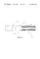
- FIG. 1is a schematic cross-section of the composite gun barrel of the present invention
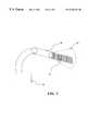
- FIG. 2is a schematic exploded view of the composite gun barrel of the present invention
- FIG. 3is a schematic cross-section of the composite gun barrel of the present invention along the lines 4 of FIG. 2;
- FIG. 4is a schematic cross-section of the composite gun barrel of the present invention at the beginning of construction.
- FIGS. 5-8are schematics which show steps of construction of the composite gun barrel of the present invention.
- the composite tube for a gun barrel of the present inventionis generally shown in the Figures as reference numeral 10 .
- the gun barrel 10further comprises an inner tubular metal liner 12 having a longitudinal bore axis A.
- a resin matrix material 14surrounds the liner 12 and comprises a plurality of longitudinal carbon fibers 15 aligned parallel with the longitudinal bore axis A.
- the longitudinal carbon fibers 15are under compression along the longitudinal axis A as will be described below.
- the liner 12has a breech end 16 and a muzzle end 18 .
- the gun barrelincludes a breech piece 22 attached to the breech end 16 and a muzzle piece 20 attached to the muzzle end 18 to compress the carbon fibers therebetween.
- the breech piece 22 and muzzle piece 20may be made of any suitable metal, such as brass, copper, or steel. Preferably, they arc steel.
- the muzzle piece 20has a central core 24 adapted to surround the resin matrix material 14 a at the muzzle end 18 ; and the breech piece 22 has a central core 25 adapted to surround the resin matrix material 14 b at the breech end 16 .
- the breech piecemay go approximately 2 inches over the resin matrix material 14 b .
- the muzzle piece 20may go approximately 1 inch over the resin matrix material 14 a.
- An adhesive material 26is adapted to secure the muzzle piece to the resin matrix material 14 a at the muzzle end 18 and to secure the breech piece 22 to the resin matrix material 14 b at the breech end 16 .
- the adhesivealso secures the breech piece 22 to the metal liner 12 .
- the muzzle piece 20 and breech piece 22may be secured by threads or by a combination of threads and adhesive material. It has been found that a combination of threads and adhesive material provides the maximum extraction of harmonics from the barrel/receiver combination.
- the breech piecethus ties the steel of the breech piece to the metal liner and the steel of the breech piece to the resin matrix material so that any vibrations that reach the breech piece are reflected back into the resin matrix material and there absorbed.
- the muzzle pieceties the metal liner to the resin matrix material to reflect any vibrations reaching the muzzle piece into the resin matrix material for absorption.
- the resin matrix material 14comprises a plurality of layers of longitudinal carbon fibers 15 embedded therein.
- the longitudinal carbon fibers 15are graphite.
- the adhesive material 26is an epoxy resin.
- the liner 12protrudes from the resin matrix material 14 at the breech end 16 , as best seen in FIG. 2 .
- the breech piece 22has an extension 28 encompassing the protruded liner.
- the protruded liner 12is externally threaded to mate with internal threads on the breech piece extension 28 .
- the resin matrix material 14 a at the muzzle end 18is externally threaded, as shown in FIG. 2, to mate with internal threads on the muzzle piece 20 .
- the liner 12works best with a wall thickness in a range of about 0.032 to 0.085 inches. Greater thicknesses could be used, but would add to the weight of the barrel.
- the muzzle piece 20 and breech piece 22work optimally with wall thicknesses of about 0.032 to 0.085 inches about the externally threaded matrix material and protruded liner, respectively.
- the linerpreferably has a first section 30 at the breech end and a narrower second section 32 adjoining the first section, and further comprising a radius 34 between the first section and the second section.
- the radius 34is optimally about 3 ⁇ 4 inch.
- the radius 34allows very heavy vibrations generated by cartridge detonation in the chamber to be absorbed immediately into the resin matrix material 14 , thus dampening the vibrations. It also allows the first section to be wider and have thicker walls than the second section, which is important as the first section 30 is nearest the chamber of the gun.
- FIG. 4A method of manufacturing the gun barrel 10 of the present invention is illustrated beginning with FIG. 4 .
- the metal liner 12has been ground down from its original thickness to a thickness of about 0.032 to 0.085 inches.
- the first few layers of resin matrix material 14have been added.
- the material 14comes in a pre-formed no-scrim, carbon fiber mat.
- the materialis available from a number of sources, including Toray, Inc., 16501 Ventura Blvd., Encino, Calif. 91436.
- the materialincludes a resin in the mat.
- the material 14is wrapped in layers around the metal liner 12 under extreme pressure in a manner similar to rolling a cigarette until the thickness needed for the barrel has been achieved.
- the carbon fiber matapproximately 0.004 inches thick, is wrapped on through a length of mat.
- a shorter length of matis wrapped on.
- the extreme pressuremay be applied mechanically.
- the liner 12 and resin matrix material 14may be inserted into a silicone bag, 40 , available from Aero Rubber Co., Bridgeview, Ill.
- the internal diameter of the silicone bagmust be less than the outer diameter of the barrel, in order to compress the barrel.
- the barrel 10may optimally be inserted into the silicone bag 40 by connecting an air pressure source 42 to one end of the bag 40 , putting a funnel 44 of appropriate diameter into the other end, inserting the barrel 10 into the funnel 44 to block the other end of the bag (FIG. 5 ), inflating the bag 40 with the air pressure source (FIG. 6 ), sliding the barrel 10 into the silicone bag 40 (FIG. 7 ), and removing the air pressure.
- the bag 40will then collapse and exert a great deal of pressure on the resin matrix material 14 (FIG. 8 ).
- the silicone bag and barrelare heated in a curing oven and cured while still under compression.
- the temperature and length of time used for curingwill vary with different matrix materials and thicknesses, but a suitable temperature and time has been found to be about 300 to 350 degrees Fahrenheit for one to two hours.
- the silicone bags with barrelsare then removed from the oven, the air pressure source is reattached to the bag, the bag is inflated, and the barrel is removed.
- the barrelis then lathed and sanded to produce the proper diameter, concentric with the longitudinal axis of the liner 12 .
- adhesive 26is applied to the externally threaded liner at the breech end 16 and the breech piece 22 is attached to the externally threaded liner 12 .
- adhesive 26is applied to the externally threaded resin matrix material 14 a at the muzzle end 18 and the muzzle piece 20 is attached to the externally threaded resin matrix material, as best seen in FIG. 2 .
- the breech piece and muzzle pieceAs the breech piece and muzzle piece are threaded onto the barrel 10 , they compress the resin matrix material 14 between them, making it able to absorb vibrations more readily.
Landscapes
- Engineering & Computer Science (AREA)
- General Engineering & Computer Science (AREA)
- Lining Or Joining Of Plastics Or The Like (AREA)
- Joining Of Building Structures In Genera (AREA)
- Laminated Bodies (AREA)
Abstract
Description
Claims (18)
Priority Applications (3)
| Application Number | Priority Date | Filing Date | Title |
|---|---|---|---|
| US09/343,868US6230429B1 (en) | 1999-06-30 | 1999-06-30 | Composite tube for gun barrel |
| PCT/US2000/009268WO2001002789A2 (en) | 1999-06-30 | 2000-04-07 | Composite tube for gun barrel |
| US09/765,247US6457274B2 (en) | 1999-06-30 | 2001-01-18 | Composite tube for gun barrel |
Applications Claiming Priority (1)
| Application Number | Priority Date | Filing Date | Title |
|---|---|---|---|
| US09/343,868US6230429B1 (en) | 1999-06-30 | 1999-06-30 | Composite tube for gun barrel |
Related Child Applications (1)
| Application Number | Title | Priority Date | Filing Date |
|---|---|---|---|
| US09/765,247DivisionUS6457274B2 (en) | 1999-06-30 | 2001-01-18 | Composite tube for gun barrel |
Publications (1)
| Publication Number | Publication Date |
|---|---|
| US6230429B1true US6230429B1 (en) | 2001-05-15 |
Family
ID=23348033
Family Applications (2)
| Application Number | Title | Priority Date | Filing Date |
|---|---|---|---|
| US09/343,868Expired - LifetimeUS6230429B1 (en) | 1999-06-30 | 1999-06-30 | Composite tube for gun barrel |
| US09/765,247Expired - LifetimeUS6457274B2 (en) | 1999-06-30 | 2001-01-18 | Composite tube for gun barrel |
Family Applications After (1)
| Application Number | Title | Priority Date | Filing Date |
|---|---|---|---|
| US09/765,247Expired - LifetimeUS6457274B2 (en) | 1999-06-30 | 2001-01-18 | Composite tube for gun barrel |
Country Status (2)
| Country | Link |
|---|---|
| US (2) | US6230429B1 (en) |
| WO (1) | WO2001002789A2 (en) |
Cited By (9)
| Publication number | Priority date | Publication date | Assignee | Title |
|---|---|---|---|---|
| US6664456B2 (en)* | 2001-04-03 | 2003-12-16 | Philip Momchilovich | Harmonic vibration damping device for musical instruments and firearms |
| US6889464B2 (en) | 2003-06-04 | 2005-05-10 | Michael K. Degerness | Composite structural member |
| US20070261286A1 (en)* | 2006-02-23 | 2007-11-15 | Sturm, Ruger & Company, Inc. | Composite firearm barrel reinforcement |
| US7934332B2 (en) | 2006-02-23 | 2011-05-03 | Sturm, Ruger & Company, Inc. | Composite firearm barrel |
| US9796057B2 (en) | 2015-01-15 | 2017-10-24 | Saeilo Enterprises, Inc. | Gun barrel assembly |
| US11385013B2 (en) | 2016-07-01 | 2022-07-12 | Blackpowder Products, Inc. | Hybrid carbon—steel firearm barrel |
| US20230022445A1 (en)* | 2016-12-29 | 2023-01-26 | Aaron E. Painter | Firearm barrel with outer sleeve |
| USD1018757S1 (en) | 2020-09-17 | 2024-03-19 | Blackpowder Products, Inc. | Firearm barrel |
| US12429299B1 (en) | 2016-12-29 | 2025-09-30 | Blackstone Firearms, Llc | Firearm barrel with non-metal outer sleeve |
Families Citing this family (7)
| Publication number | Priority date | Publication date | Assignee | Title |
|---|---|---|---|---|
| US20050108916A1 (en)* | 2003-08-28 | 2005-05-26 | Ra Brands, L.L.C. | Modular barrel assembly |
| US7775200B2 (en)* | 2005-05-23 | 2010-08-17 | Anderson Kenneth K | Barrel system for a paintball marker |
| US20070256345A1 (en) | 2006-05-04 | 2007-11-08 | Hall David R | A Rigid Composite Structure with a Superhard Interior Surface |
| US20080251060A1 (en)* | 2007-01-08 | 2008-10-16 | Glen Mitchell Thurber | Carbon/aluminum paintball barrel with built in silencer |
| US7676980B2 (en)* | 2007-07-25 | 2010-03-16 | Terrence Dwight Bender | Adjustable mass tuner for rifle barrels |
| US20100132241A1 (en)* | 2008-05-19 | 2010-06-03 | Mancini Ralph J | Method for accurizing a firearm |
| TWM348936U (en)* | 2008-09-03 | 2009-01-11 | Gan Yao Guo | Paint ball gun |
Citations (13)
| Publication number | Priority date | Publication date | Assignee | Title |
|---|---|---|---|---|
| US4137351A (en)* | 1978-04-03 | 1979-01-30 | The United States Of America As Represented By The Secretary Of The Army | Filament/epoxy camouflage launch tubes |
| US4485721A (en)* | 1980-04-10 | 1984-12-04 | Her Majesty The Queen In Right Of Canada, As Represented By The Minister Of National Defence Of Her Majesty's Canadian Government | Rifled fiber reinforced gun barrel |
| US4641450A (en) | 1984-04-19 | 1987-02-10 | Balzers Aktiengesellschaft | Tube having strain-hardened inside coating |
| US4646615A (en) | 1984-05-15 | 1987-03-03 | Her Majesty The Queen In Right Of Canada | Carbon fibre gun barrel |
| US4685236A (en) | 1984-05-30 | 1987-08-11 | Sam May | Graphite/metal matrix gun barrel |
| US4729806A (en) | 1985-08-13 | 1988-03-08 | Affarsverket Ffv | Method for making tubes having low weight |
| US5054224A (en) | 1990-11-19 | 1991-10-08 | The United States Of America As Represented By The Secretary Of The Army | Apparatus and method for a composite polymer rifling disposable gun tube |
| US5125179A (en) | 1991-04-08 | 1992-06-30 | The United States Of America As Represented By The Secretary Of The Air Force | Nonmetallic tubular structure |
| US5191165A (en) | 1990-10-01 | 1993-03-02 | Statoil Europarts Ab | Ordnance barrels |
| US5600912A (en) | 1995-11-29 | 1997-02-11 | Smith; David B. | Composite tube for a gun barrel |
| US5692334A (en)* | 1995-12-18 | 1997-12-02 | Roland J. Christensen Family Limited Partnership | Primarily independent composite/metallic gun barrel |
| US5804756A (en)* | 1995-12-18 | 1998-09-08 | Rjc Development, L.C. | Composite/metallic gun barrel having matched coefficients of thermal expansion |
| US5928799A (en)* | 1995-06-14 | 1999-07-27 | Ultramet | High temperature, high pressure, erosion and corrosion resistant composite structure |
Family Cites Families (3)
| Publication number | Priority date | Publication date | Assignee | Title |
|---|---|---|---|---|
| US2845741A (en)* | 1955-04-27 | 1958-08-05 | Olin Mathieson | Composite firearm barrel |
| US4435455A (en)* | 1983-01-10 | 1984-03-06 | United Technologies Corporation | Compliant composite tubular liners of fiber reinforced glass/glass-ceramic having utility as gun barrel liners |
| US5657568A (en) | 1995-12-18 | 1997-08-19 | Roland J. Christensen | Composite/metallic gun barrel having a differing, restrictive coefficient of thermal expansion |
- 1999
- 1999-06-30USUS09/343,868patent/US6230429B1/ennot_activeExpired - Lifetime
- 2000
- 2000-04-07WOPCT/US2000/009268patent/WO2001002789A2/enactiveApplication Filing
- 2001
- 2001-01-18USUS09/765,247patent/US6457274B2/ennot_activeExpired - Lifetime
Patent Citations (13)
| Publication number | Priority date | Publication date | Assignee | Title |
|---|---|---|---|---|
| US4137351A (en)* | 1978-04-03 | 1979-01-30 | The United States Of America As Represented By The Secretary Of The Army | Filament/epoxy camouflage launch tubes |
| US4485721A (en)* | 1980-04-10 | 1984-12-04 | Her Majesty The Queen In Right Of Canada, As Represented By The Minister Of National Defence Of Her Majesty's Canadian Government | Rifled fiber reinforced gun barrel |
| US4641450A (en) | 1984-04-19 | 1987-02-10 | Balzers Aktiengesellschaft | Tube having strain-hardened inside coating |
| US4646615A (en) | 1984-05-15 | 1987-03-03 | Her Majesty The Queen In Right Of Canada | Carbon fibre gun barrel |
| US4685236A (en) | 1984-05-30 | 1987-08-11 | Sam May | Graphite/metal matrix gun barrel |
| US4729806A (en) | 1985-08-13 | 1988-03-08 | Affarsverket Ffv | Method for making tubes having low weight |
| US5191165A (en) | 1990-10-01 | 1993-03-02 | Statoil Europarts Ab | Ordnance barrels |
| US5054224A (en) | 1990-11-19 | 1991-10-08 | The United States Of America As Represented By The Secretary Of The Army | Apparatus and method for a composite polymer rifling disposable gun tube |
| US5125179A (en) | 1991-04-08 | 1992-06-30 | The United States Of America As Represented By The Secretary Of The Air Force | Nonmetallic tubular structure |
| US5928799A (en)* | 1995-06-14 | 1999-07-27 | Ultramet | High temperature, high pressure, erosion and corrosion resistant composite structure |
| US5600912A (en) | 1995-11-29 | 1997-02-11 | Smith; David B. | Composite tube for a gun barrel |
| US5692334A (en)* | 1995-12-18 | 1997-12-02 | Roland J. Christensen Family Limited Partnership | Primarily independent composite/metallic gun barrel |
| US5804756A (en)* | 1995-12-18 | 1998-09-08 | Rjc Development, L.C. | Composite/metallic gun barrel having matched coefficients of thermal expansion |
Cited By (15)
| Publication number | Priority date | Publication date | Assignee | Title |
|---|---|---|---|---|
| US6664456B2 (en)* | 2001-04-03 | 2003-12-16 | Philip Momchilovich | Harmonic vibration damping device for musical instruments and firearms |
| US6889464B2 (en) | 2003-06-04 | 2005-05-10 | Michael K. Degerness | Composite structural member |
| US8316568B2 (en) | 2006-02-23 | 2012-11-27 | Sturm, Ruger & Company, Inc. | Composite firearm barrel reinforcement |
| US20070261286A1 (en)* | 2006-02-23 | 2007-11-15 | Sturm, Ruger & Company, Inc. | Composite firearm barrel reinforcement |
| US7921590B2 (en) | 2006-02-23 | 2011-04-12 | Strum, Ruger & Company, Inc. | Composite firearm barrel reinforcement |
| US7934332B2 (en) | 2006-02-23 | 2011-05-03 | Sturm, Ruger & Company, Inc. | Composite firearm barrel |
| WO2009038852A3 (en)* | 2007-07-18 | 2009-05-07 | Sturm Ruger & Co | Composite firearm barrel reinforcement |
| US9796057B2 (en) | 2015-01-15 | 2017-10-24 | Saeilo Enterprises, Inc. | Gun barrel assembly |
| US11385013B2 (en) | 2016-07-01 | 2022-07-12 | Blackpowder Products, Inc. | Hybrid carbon—steel firearm barrel |
| US11732988B2 (en) | 2016-07-01 | 2023-08-22 | Blackpowder Products, Inc. | Hybrid carbon—steel firearm barrel |
| US12169106B2 (en) | 2016-07-01 | 2024-12-17 | Blackpowder Products, Inc. | Hybrid carbon-steel firearm barrel |
| US20230022445A1 (en)* | 2016-12-29 | 2023-01-26 | Aaron E. Painter | Firearm barrel with outer sleeve |
| US12359887B2 (en)* | 2016-12-29 | 2025-07-15 | Blackstone Firearms, Llc | Firearm barrel with outer sleeve |
| US12429299B1 (en) | 2016-12-29 | 2025-09-30 | Blackstone Firearms, Llc | Firearm barrel with non-metal outer sleeve |
| USD1018757S1 (en) | 2020-09-17 | 2024-03-19 | Blackpowder Products, Inc. | Firearm barrel |
Also Published As
| Publication number | Publication date |
|---|---|
| WO2001002789A3 (en) | 2003-02-27 |
| US6457274B2 (en) | 2002-10-01 |
| WO2001002789A2 (en) | 2001-01-11 |
| US20020002786A1 (en) | 2002-01-10 |
Similar Documents
| Publication | Publication Date | Title |
|---|---|---|
| US6230429B1 (en) | Composite tube for gun barrel | |
| US5600912A (en) | Composite tube for a gun barrel | |
| US10001337B2 (en) | Composite multi-lobe projectile barrel | |
| EP0970340B1 (en) | Small caliber gun barrel | |
| US5165040A (en) | Pre-stressed cartridge case | |
| US6497065B1 (en) | Firearm barrel having protective sleeve | |
| US6889464B2 (en) | Composite structural member | |
| US7866079B2 (en) | Modular barrel assembly | |
| US4646615A (en) | Carbon fibre gun barrel | |
| US7503249B2 (en) | Barrels for electromagnetic guns | |
| US20190226786A1 (en) | Carbon Fiber Barrel and Method for Making the Same | |
| US12169106B2 (en) | Hybrid carbon-steel firearm barrel | |
| US8794122B2 (en) | Weapons system construction and modification including improved gas management system | |
| US5804756A (en) | Composite/metallic gun barrel having matched coefficients of thermal expansion | |
| US3641870A (en) | Shingle-wrap liner for a gun barrel | |
| AU2022200834B2 (en) | Hybrid carbon - steel firearm barrel | |
| US20150330729A1 (en) | Weapons system modification for improved piston system | |
| US5216194A (en) | Lightweight molded cartridge case and nozzle assembly for recoilless launch systems | |
| EP0862721B1 (en) | Composite/metallic gun barrel | |
| HK1090689B (en) | Modular barrel assembly |
Legal Events
| Date | Code | Title | Description |
|---|---|---|---|
| AS | Assignment | Owner name:MAGNUM RESEARCH, INC., MINNESOTA Free format text:ASSIGNMENT OF ASSIGNORS INTEREST;ASSIGNOR:SMITH, DAVID B.;REEL/FRAME:010117/0282 Effective date:19990707 | |
| STCF | Information on status: patent grant | Free format text:PATENTED CASE | |
| FPAY | Fee payment | Year of fee payment:4 | |
| AS | Assignment | Owner name:U.S. BANK NATIONAL ASSOCIATION, MINNESOTA Free format text:SECURITY AGREEMENT;ASSIGNOR:MAGNUM RESEARCH, INC.;REEL/FRAME:016489/0362 Effective date:20050826 | |
| FPAY | Fee payment | Year of fee payment:8 | |
| AS | Assignment | Owner name:SAEILO ENTERPRISES, INC.,NEW YORK Free format text:ASSIGNMENT OF ASSIGNORS INTEREST;ASSIGNOR:MAGNUM RESEARCH, INC.;REEL/FRAME:024563/0575 Effective date:20100609 Owner name:SAEILO ENTERPRISES, INC., NEW YORK Free format text:ASSIGNMENT OF ASSIGNORS INTEREST;ASSIGNOR:MAGNUM RESEARCH, INC.;REEL/FRAME:024563/0575 Effective date:20100609 | |
| REMI | Maintenance fee reminder mailed | ||
| FPAY | Fee payment | Year of fee payment:12 | |
| SULP | Surcharge for late payment | Year of fee payment:11 |