US6230006B1 - Test system for remotely testing switches within a telecommunications network - Google Patents
Test system for remotely testing switches within a telecommunications networkDownload PDFInfo
- Publication number
- US6230006B1 US6230006B1US09/146,606US14660698AUS6230006B1US 6230006 B1US6230006 B1US 6230006B1US 14660698 AUS14660698 AUS 14660698AUS 6230006 B1US6230006 B1US 6230006B1
- Authority
- US
- United States
- Prior art keywords
- call processor
- remote call
- controller
- remote
- audio
- Prior art date
- Legal status (The legal status is an assumption and is not a legal conclusion. Google has not performed a legal analysis and makes no representation as to the accuracy of the status listed.)
- Expired - Lifetime
Links
Images


Classifications
- H—ELECTRICITY
- H04—ELECTRIC COMMUNICATION TECHNIQUE
- H04W—WIRELESS COMMUNICATION NETWORKS
- H04W24/00—Supervisory, monitoring or testing arrangements
Definitions
- This inventionrelates generally to a system for testing the operation of a telecommunications network and more specifically to a system for remotely testing one or more switches within a telecommunications network.
- Telecommunications networkscan generally be divided into two components, cellular networks and conventional land-line networks. While the cellular networks support wireless telephone services and the land-line networks support conventional telephone service, the networks and services generally overlap in that a user of a wireless telephone service can place a phone call through the cellular network to the land-line network to thereby establish a telephone link with a conventional telephone, and conversely, a user of a conventional telephone service can place a phone call through the land-line network to the cellular network to thereby establish a phone link with a wireless telephone. Furthermore, in some instances, the cellular network is comprised of communication links that may, at times, be considered part of the land-line network.
- a cellular networkis bounded by a geographic territory.
- the AT&T cellular networkgenerally services the entire continental United States while the Cellular One cellular network generally services the east coast of the United States.
- a cellular networkis generally comprised of multiple service areas, each of which is subdivided into multiple cells.
- Each cellhas a base station for receiving and transmitting phone calls between a mobile phone and the cell, and the base stations are connected to a switch normally located in a mobile telephone switching office (MTSO).
- MTSOmobile telephone switching office
- the MTSOgenerally manages the multiple switches in the cellular network and maintains a communications link between the cellular network and the land-line network.
- the cell base stationreceives the phone call and forwards it to the service area switch where it is forwarded to the destination device.
- the service area switchforwards the phone call to the switch of the destination service area where it is forwarded to the bases station of the destination cell for transmission to the destination wireless phone, thereby establishing a communication link between two wireless phones within the same cellular network.
- the MTSOdirects the call from the calling service area switch to a switch associated with the land-line network where the call is connected to the conventional phone.
- the calling service area switchforwards the phone call through the land-line network to the destination cellular network where it is directed through the switch of destination service area to the base station of the destination cell for transmission to the destination phone, thereby establishing a communication link from the calling wireless phone to the destination wireless phone by way of the calling cellular network, the land-line network and the destination cellular network.
- a phone call initiated by a wireless, phonemay involve many different switches in many different networks.
- the first switch accessed by the calleris the “billing switch” responsible for tracking and recording all the various charges associated with the phone call, including enhanced services.
- Such chargesmight include basic charges, in-network roaming charges, out-of-network roaming charges, land-line fees, long distance fees or other cellular network fees as will be appreciated by one of skill in the art.
- a billing switchthat improperly tracks fees associated with a phone call or with any enhanced services provided by the service provider, results in lost revenue to, or over billing by, the service provider. Therefore, it is critical to the service provider that the billing switches consistently and accurately track and record fees.
- a user of a cellular phonewill execute a subscription agreement with one or more service providers which allows the user to place calls within the service providers cellular network.
- the usergenerally enters subscription agreements with service providers having cellular networks covering the geographic area in which the user normally makes phone calls.
- service providers with which the user has a subscription agreementwill be referred to as “home” service providers.
- the various service providershave executed agreements whereby a subscriber to a service provider can use the services of other service providers, subject to a fee, and the “home” service provider will appropriately charge the subscriber.
- Every wireless phonecontains an Electronic Serial Number (ESN) and a Numbered Assignment Modules (NAMs) which together indicate the “home” service providers to which the phone is associated (hereafter the ESN and the NAM will be collectively referred to as the “NAM”).
- ESNElectronic Serial Number
- NAMsNumbered Assignment Modules
- the associated billing switchrecognizes the NAM in order to determine whether the phone is communicating with a “home” or “non-home” service provider in order to properly track and allocate fees. Initiating a call within the network of a “home” service provider will be charged differently than initiating a call within the network of a “non-home” service provider.
- calls initiated within “non-home” service providerswill be charged differently depending upon the specific agreement between the non-home service provider and the home service provider.
- Each billing switchtracks and records the fees associated with a phone call through use of a “billing table” that is preprogrammed into the switch by the service provider.
- the billing tablerecognizes charges associated with each call including any charges for enhanced services (i.e. call waiting) subscribed to by a user.
- the switcheswill be reprograrmned with updated billing tables at various times including whenever a new service area is added or removed from the cellular network; whenever a subscriber is added or deleted from the service provider; whenever the cellular network fees are changed; whenever the agreement between the cellular network and other networks changes.
- the hardware and or software of a switchmay be periodically upgraded (e.g., a base station may be added to the switches' service area or the switch may be reprogrammed with “upgraded” software for bug fixes or feature enhancements).
- the switchundergoes maintenance or routing changes that change or effect the interaction between the switches.
- the upgrades and maintenancesometimes result in errors associated with billing and network operations causing the switch to malfunction as it processes calls.
- the switchis reprogrammed, upgraded, or undergoes maintenance, it is critical that the service provider have an efficient means for verifying that the various switches function properly and correctly track and record fees.
- switches handling the callare responsible for properly routing and billing the call.
- a switch that is installed, reprogrammed, upgraded, or maintained improperlymay result in improperly routed and/or billed calls and thus lost revenue to the service provider.
- switchesare being installed in new networks and because switches in existing networks are continuously reprogrammed, upgraded and/or maintained, a system for testing the proper operation of the numerous switches within a telecommunications network, and thus the proper routing and billing of calls to and from such network, is necessary to maintain an efficient network.
- there are two such types of systems available to service providersone made by Rotodata and the other made by Comarco.
- the Comarco systemincludes a testing device that places a wireless call to a service area of a cellular network where such call is routed through the switch associated with the service area to a destination device whereby a communication link is established between the testing device and the destination device.
- the destination devicemay be a mobile or land-line phone offering a pre-recorded audio message that is communicated over the established communications link to the user of the testing device where proper operation of the switch may be confirmed.
- the testing devicemay also be equipped with multiple phones such that the testing device may establish a communication link from a first one of said phones to a second one of said phones thereby establishing the testing device as the destination device.
- the testing devicemust be located “in the field” (e.g., geographically within the service area) so as to be capable of wireless communication with the service area.
- the testing deviceis designed to be locally controlled in that setting the parameters of the testing device and/or initiating the test requires a technician to be located “in the field” with the testing device. This limitation also requires that a field technician travel to the various service areas of the cellular network in order to test the numerous switches within the network.
- Another shortfall of the Comarco Systemis that the testing device does not have the capability to record audio received from the destination device thereby requiring that a technician be located in the field with the testing device during testing in order for the technician to hear the quality of the audio received at the test device.
- Yet another shortfall of the Comarco systemis that the presence of the technician in the field prevents the technician from accessing the billing; records of the call, which are normally located in a central office, and therefore from verifying proper billing simultaneously with the verification of the call. Still yet another shortfall of the Comarco system is that it cannot complete calls from one testing device to a second testing device. A further shortfall of the Comarco system is that it does not enable the user to verify the audio of the placed call in both directions without a technician being present at each end of the call. Yet a further shortfall of the Comarco system is that it cannot interactively control or measure the testing being performed by the testing device.
- the Rotodata systemincludes a testing device that places a wireless call to a service area of a cellular network where such call is routed through the switch associated with the service area to a destination device.
- the destination deviceis a pre-recorded audio message that is communicated to the user of the testing device to confirm proper operation of the switch.
- the Rotodata systemhas remote control feature that permits operation of multiple testing devices from a remote location.
- the remote capabilitydoes not permit audio from the testing device to be communicated to the remote control location thereby forcing the user to rely on non-audio information in the call verification process.
- This limitationprevents the user from remotely verifying whether the audio was received, or the quality of the audio received, at either the testing device or the remote control location and prevents the user from remotely testing services such as 911 emergency service, voice mail, call forwarding, call waiting, no answer transfer and messaging, and any other service that can be verified through an interactive audio process. Accessing the audio requires the user to be in local control of the testing device which requires the technician to be located in the field with the testing device.
- Another shortfall of the Rotodata systemis that the remote capability does not permit audio from the remote control location to be communicated to the testing device or the destination device thereby preventing the user from audio interaction with either of the devices.
- This limitationalso prevents the user from testing services such as voice mail, call forwarding, call waiting, no answer transfer and messaging or any other service that can be verified through an interactive audio process.
- the remote controlis implemented over an unsecured POTS line.
- the Rotodata systemdoes not allow for individual call control of each remote unit. For example, the remote units will accept a 24 hour series of commands to run without master control such that the user will lose 24 hours of test if a test error occurs.
- an object of the inventionis a system for remotely testing a switch of a telecommunications network where audio received at the testing device is communicated to the remote control location whereby the user can verify the proper completion of the call, the audio quality, and the billing records.
- Another object of the inventionis a system for remotely testing a switch of a telecommunication network where audio from the remote control location is communicated to the testing device.
- Yet another object of the inventionis a system for remotely testing a switch of a telecommunication network where audio from the remote control location is communicated through the testing device to the destination device.
- Still yet another object of the inventionis a system for remotely testing a switch of a telecommunications network where such system is capable of centralized remote management of multiple testing devices and centralized remote testing of multiple switches.
- a further object of the inventionis to provide a system for remotely testing a witch of a telecommunications network where a communication link is established from a first testing device through a switch to a second testing device where the user at a remote control location has access to audio received at the first testing device and the second testing device.
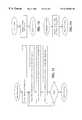
- FIG. 1is an illustration of the system of the present invention.
- FIG. 2is a diagram of the controller and the Remote Call Processor of the present invention.
- FIG. 3is a diagram of the system of the present invention.
- FIGS. 4-13are flow diagrams of the present invention.
- the present inventionis a system for centrally and remotely testing switches of cellular and conventional telecommunications network wherein a controller located at a remote location establishes a communication link with a Remote Call Processor (RCP) and provides instructions to the RCP to thereby prompt the RCP to establish a communication link from the RCP through a switch to a destination device whereby audio from said destination device is communicated, by way of the switch and the RCP, to the controller in order to verify that the switch properly routed and billed the call.
- RCPRemote Call Processor
- the destination devicemay be a service provided by such network or it may be another RCP.
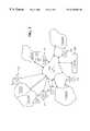
- FIG. 1is an illustration of one embodiment of the present invention.
- the system of the present inventionis a system for testing a switch 40 of a telecommunications network 50 .
- the telecommunications network 50is a cellular network comprised of multiple service areas 52 and 54 .
- the system of the present inventionincludes one or more remote call processors (RCPs) 20 , 30 and a controller 10 .
- the RCPs 20 , 30include phone means for establishing a communication link from the RCP 20 through the calling area switch 40 to a destination device such that audio from the destination device is communicated to the RCP 20 .
- the destination devicemay be a prerecorded voice mail box established by the service provider or, as further described below, another RCP 30 , or any other device that assists in the verification of the operation of the switch 40 .
- the controller 10is for remotely controlling operation of the RCP 20 .
- the controllerincludes remote communication means for establishing a communication link between the controller 10 and the RCP 20 such that audio received at the RCP 20 will be communicated to the controller 10 .
- the controller 10also includes means for instructing the RCP 20 to initiate a phone call to the destination device. Functionally, an operator of the system prompts the controller 10 to establish a communication link between the controller 10 and the RCP 20 and instructs the RCP 20 to initiate a phone call to a selected destination device. In response to such instructions, the RCP 20 initiates a phone call to the destination device and establishes a communication link from the RCP 20 through the calling area switch 40 to the destination device (not shown).
- audio from the destination deviceis communicated through the calling area switch 40 and the RCP 20 to the controller 10 .
- the operator of the systemcan then evaluate the audio received at the controller 10 to determine if the calling area switch 40 properly connected the RCP 20 to the destination device.
- the operatormay further determine if the calling area switch properly switched the call and billed for the call by reviewing the translation tables and billing records of the switch, which preferably would be accessible at the location of the controller.
- the destination devicemay be a voice mail service, a call waiting service, a call forwarding service, a no answer transfer service, a messaging service, a voice recognition service or any other of the types of services provided in such a network.
- the destination devicemay prompt the user, through a pre-recorded voice, to select from a number of options through use of the telephone keypad.
- the pre-recorded voicewould be forwarded to the RCP 20 , and thus to the controller 10 , for a response.
- the controllerincludes means for instructing the RCP 20 to respond to such queries.
- the operatormay verify the proper operation of the switch 40 by verifying that the call was established from the RCP 20 to the correct destination device and that the 2-way audio transmission communicated from the RCP 20 through the switch 40 to the destination device was enabled.
- the destination devicemay be any type of device sufficient to verify that the communication link through switch 40 was properly established.
- the destination devicemay be located in another service area, another cellular network or the PSTN, as further described below.
- the destination devicemay be a second or third wireless phone means located in the RCP 20 , whereby upon being prompted by the controller 10 , the RCP 20 establishes a communication link from a first phone means located in the RCP 20 , through the calling area switch 40 , to the second or third phone means located in the RCP 20 .
- the destination devicemay be a conventional phone means located in the RCP 20 , whereby upon being prompted by the controller 10 , the RCP 20 establishes a communication link from the wireless phone means located in the RCP 20 , through the calling area switch 40 , to a conventional phone means located in the RCP 20 .
- the destination deviceis a second RCP 30 that is in wireless communication with either the first service area 52 or a second service area 54 as shown.
- the userprompts the controller to establish a communication link with RCP 20 and RCP 30 .
- the controllerthen instructs the RCP 20 to initiate a phone call to RCP 30 and instructs RCP 30 to expect a phone call.
- the RCP 20attempts to establish a communication link through calling area switch 40 and calling area switch 42 to RCP 30 . If successful, the RCP 30 sends data to the controller indicating the successful completion of the call at which time the user may verify that the call was properly billed by referencing the billing records. If RCP 30 does not receive the call within a predetermined period of time, RCP 30 will send data to the controller indicating that the call has not been received, at which point the user may determine that one or more of the switches 40 and 42 did not properly, route the call.
- a successful callwill establish a communication link, resembling a communication loop, from the controller 10 , through RCP 20 , calling area switch 40 , calling area switch 42 , and RCP 30 to the controller 10 .
- the communication link between the controller 10 and RCPs 20 and 30may be comprised of the PSTN 60 .
- the communication link between calling area switch 40 and calling area switch 42may be comprised of leased lines that at other times may be considered part of the PSTN.
- the communication link between RCP 20 and RCP 30is generally a conventional wireless telephone link capable of passing audio in either direction.
- the communication links 22 and 32 between the controller 10 and the RCPs 20 and 30 , respectively,will be further described below. Generally, however, these communication links may be such that they either pass one-way audio or two-way audio depending upon the specific design chosen.
- the systemmay have two modes of operation, a non-audio mode and an audio mode. In the non-audio mode, non-audio control and status information may be passed between the controller and each of the RCPs. In this mode, audio is not used for call verification. Such control and status information may be any type of remote control and status information known in the art. In the non-audio mode, the controller will not receive or communicate audio.
- audiois also passed between the controller 10 and the RCPs 20 and 30 .
- communication links 22 and 32are one-way audio
- audio received at RCP 20is communicated to the controller over communication link 22 and audio generated at the controller 10 is communicated to RCP 30 over communication link 32 .
- audio generated at the controllerwill be communicated to RCP 30 over communication link 32 ; audio from RCP 30 will be communicated to RCP 20 through calling area switches 42 and 40 ; and audio from RCP 20 will be communicated to the controller 10 over communication link 22 , thereby creating a one-way audio loop that begins and ends at the controller 10 .
- the operatorcan verify that audio is adequately passing from RCP 30 through the calling area switches to RCP 20 by communicating an audio signal from controller 10 over communication link 32 to RCP 30 and verifying that such signal is thereafter received at controller 10 over communication link 22 .
- the audio signalwould be generated by the operator speaking into a microphone provided with the controller 10 , or through a prerecorded text or speech message which may include a text to speech function as will be appreciated by one of skill in the art, the details of which will be further discussed below, and the audio signal would be received by a speaker provided with the controller 10 , thereby enabling the operator to verify the call by simply speaking into a microphone, or initiating the pre-recorded text or speech message, and listening to the speaker.
- the controller 10would be provided with an electronic switch controlled by software residing in the Controller 10 , for reversing the path of the audio loop.
- Communications links 22 and 32 and the means for communicating over such linksmay be any known means for remotely communicating between two devices over a telecommunications network.
- the controller and the RCP 20 or 30include modems and the communication links 22 and 32 are conventional phone lines or wireless communication links.
- the communications links 22 and 32may be comprised of the Internet and the controller 10 and the RCP 20 or 30 include voice-over-Internet means for communicating audio over the Internet.
- communications links 22 and 32are an internal corporate intranet comprised of an Ethernet communication link where the controller 10 and the RCP 20 or 30 include an Ethernet card for passing data over an Intranet via an Ethernet communication link and include voice-over-Ethernet means for sending audio over the Ethernet Intranet communication link.
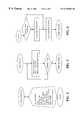
- FIG. 2is a diagram of the various embodiments of the controller and the RCP of the system of the present invention.
- the controller 100includes remote communication means for establishing a communication link between the controller 100 and the RCP 110 .
- the remote communication meansmay be comprised of a conventional computer 102 with a modem 104 for establishing a communication link between the controller 100 and the CRP 110 over a conventional phone line normally associated with the PSTN 105 such that the controller 100 can communicate control instructions to the RCP 110 and such that audio can be passed between the RCP 110 and the controller 100 .
- the modem 104 and the computer 102may be any computer or modem known to one of skill in the art to enable such communication between the controller 100 and the RCP 110 .
- the controller 100includes means for instructing the RCP 110 which essentially comprises the modem 104 and conventional software for generating and sending control instructions to the controller 110 .
- Such software for generating such control instructionsmay be any conventional or known type of software used for remote communications between devices, which are generally known in the art.
- such softwareis comprised of a combination of Microsoft “visual basic” and Microsoft “C” software that are compiled to run on a standard Pentium based personal computer.
- a user of the systemwould prompt the controller 100 to instruct the RCP 110 to initiate a call, whereby the controller 100 would establish a communication link with the RCP 110 and communicate control data over the communication link to the RCP 110 .
- the controller 100may also include and A/D converter 106 for digitizing the analog voice received at the controller 100 , whereafter such digitized voice may be stored in memory 108 .
- memory 108may be any memory known that is sufficient, to store digital audio data.
- the RCP 20includes a phone means 112 , a processor 114 , a modem 116 , and memory 118 .
- the phone means 112may be a conventional phone or in the preferred embodiment the phone means would be a conventional cellular phone.
- the cellular phonemay be capable of communicating in one or more of the types of wireless communication systems such as TDMA, CDMA, NMT, AMPS or GSM.
- the modem 116enables the communication between the controller 100 and the RCP 110 and may be any type of modem available and generally known by one of skill in the art.
- the processor 114is a Pentium based processor, and the memory 118 may be of the type generally known to those skilled in the art that is sufficient to store digital audio data.
- the modem 116receives and transmits commands and audio signals between the controller 100 and the processor 114 .
- the processor 114commands the phone 112 to place and receive calls and interrogates the phone 112 for basic information about the call which may include information related to the network performance of a particular call, and the duration of the call, etc. All information is then processed and sent back to the controller 100 for further interpretation and display to the user.
- FIG. 2 bshows another embodiment of the controller 100 and the RCP 110 of the system of the present invention.
- the communication link between the controller 100 and the RCP 110is that of a private corporate intranet comprised of an Ethernet communication link over the Internet.
- the controller 100 and the RCP 110each have an Ethernet Card 130 .
- the RCP 110further comprises means for digitizing audio received from a destination device. Such means may include an A/D and a D/A converter 111 for digitizing the analog audio received at the RCP 110 from the destination device and for analoging the digital audio received at the RCP 110 from the controller 100 , if necessary.
- audio and control signals passed between the controller 100 and the RCP 110are in a digital format and the audio received at the RCP 110 is readily stored in the memory 118 of the RCP 110 or the memory of the controller 100 .
- the phone means 112 located in the RCP 110comprises three wireless phones 120 and one or more conventional phones 122 .
- test callsmay be placed between phones of different RCPs, as described earlier, or between phones of the same RCP 110 . Additionally, calls may be placed by any one of the phones 112 to any other one of the phones. As a single call is place and received within the phone means 112 , the audio and control associated with that call will be communicated over the Ethernet medium to the controller 100 .
- the RCP 110may also include means for measuring the quality of the audio received at the RCP from the destination device. Such means would include any known means of measuring the signal strength, the signal to noise ratio and the clarity of the audio received.
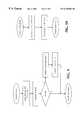
- FIG. 3shows an illustration of the system of the present invention.
- controller 200provides central control of a broad number of RCPs ( 210 , 220 , 230 , 240 , 250 and 260 ) thereby enabling fast efficient testing of multiple switches throughout various cellular and land-line networks. Tests may be performed from any RCP to any destination device which includes tests from any RCP to any other RCP.
- the systemwill have a script testing feature for testing a test call created by the user in order to ensure that the test call was created properly.
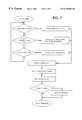
- FIGS. 4-13are flow charts illustrating the general functions of the software that resides in the controller 110 .
- FIG. 4illustrates the various mode options available to a user of the system and
- FIGS. 5-13illustrate the flow diagrams of each of the individual modes.
- the controller 110 in the preferred embodimentis comprised of a standard personal computer running the Microsoft Windows NT operating system.
- the controller functionalityincludes a methodology for managing calls (placing and receiving calls and sending and returning audio) in remote areas using one or more RCPs.
- the basic modes of the controller functionalityare as follows: administration mode, login mode, buildingscripts mode, Run Mode, scheduled mode, results mode, interactive mode, maintenance mode, help mode and service step mode.
- Administration modeincludes a process of allocating user names and selecting passwords.
- usersBy way of the main user or administrator, users will be assigned and passwords determined.
- each userThrough a tiered authorization system each user will be assigned an authorization level providing varying access to controller functionality. These access levels are identified as level one, two, and three.
- Login modeprovides entry into the system by requesting a password from the user. It also may demand that the user, for further security, change his password after every three entries into the system.
- the Build scripts modeallows for the building of test calls on the controller by 0 way of the application specific software provided thereby offering the user an implicit method of creating most types of calls that can be presently made by wireless and landline subscribers today.
- These test callsare built by listing each of presently 12 commands in the order required to place a call as needed. These commands are further enhanced by additional user entries to select phones and mobile numbers to be used, selection of audio direction and RCP to be used, decision to record audio and for how long, whether or not to answer the terminating mobile, and others.
- the test callscan be tested for accuracy by selecting a call test function that will verify the proper coding of the new test call. Additionally, key words and functions within a test call can be modified automatically through a string search and replace command.
- test calls built in the build scripts modeare executed.
- each of the commands or test steps in the listare executed in sequence thereby allowing the test call to be managed by the appropriate RCP/s.
- the scheduled modethe test calls are executed according to a predetermined schedule. In either mode the test calls are performed identically. However, responses to some of the stimulus from the wireless network may be responded to differently between the two different modes.
- run modean error in placing a call is responded to by stopping the call execution and asking for user intervention.
- scheduled modethe same error is noted and the very next test call is executed and the process continues.
- the controllerIn order to determine the performance of each call, parses the results. This performance rating is coded and stored with the results within the controller's memory. This storage includes all one way and two way audio messages received by the controller from the selected RCPs. These results are stored in a standard format so that any standard PC can read or further analyze them.
- the usercan display, analyze and manipulate the results of the test calls.
- the usercan activate and use the feature allowing audio to be sent from the controller to the RCPs.
- system information modethe user is provided information about key aspect of the operating system status such as; Software and Hardware revision levels, display resolution, time and date.
- the usermay copy stored test call lists and result files to other areas in memory.
- the controllerprovides a means of configuring each RCP in the system and the inherent devices within each RCP.
- the RCPcan be named, the cellular phones are configured for their new mobile numbers (NAMs), the cellular phones ESN can be read and the landline number can be inserted.
- RCPscan be added or deleted in this mode and the associated IP addresses for each RCP can be programmed into the RCP.
- Service step modeprovides the user an opportunity to create program steps to insert digits and delay between digits into a phone in a RCP. These can be created and named, to be drawn from the standard list of program steps provided in the build scripts mode.
Landscapes
- Engineering & Computer Science (AREA)
- Computer Networks & Wireless Communication (AREA)
- Signal Processing (AREA)
- Mobile Radio Communication Systems (AREA)
- Telephonic Communication Services (AREA)
Abstract
Description
Claims (20)
Priority Applications (6)
| Application Number | Priority Date | Filing Date | Title |
|---|---|---|---|
| US09/146,606US6230006B1 (en) | 1997-09-08 | 1998-09-03 | Test system for remotely testing switches within a telecommunications network |
| US09/799,448US6542738B2 (en) | 1997-09-08 | 2001-03-05 | Test system for remotely testing switches within a telecommunications network |
| US09/885,002US7020441B2 (en) | 1998-09-03 | 2001-06-21 | Test system for remotely testing switches within a telecommunications network |
| US10/364,152US6788934B2 (en) | 1997-09-08 | 2003-02-11 | Test system for remotely testing switches within a telecommunications network |
| US11/290,910US7231187B2 (en) | 1998-09-03 | 2005-11-30 | Test system for remotely testing switches within a telecommunications network |
| US11/742,979US20070202868A1 (en) | 1998-09-03 | 2007-05-01 | Test system for remotely testing switches within a telecommunications network |
Applications Claiming Priority (2)
| Application Number | Priority Date | Filing Date | Title |
|---|---|---|---|
| US5812697P | 1997-09-08 | 1997-09-08 | |
| US09/146,606US6230006B1 (en) | 1997-09-08 | 1998-09-03 | Test system for remotely testing switches within a telecommunications network |
Related Child Applications (1)
| Application Number | Title | Priority Date | Filing Date |
|---|---|---|---|
| US09/799,448ContinuationUS6542738B2 (en) | 1997-09-08 | 2001-03-05 | Test system for remotely testing switches within a telecommunications network |
Publications (1)
| Publication Number | Publication Date |
|---|---|
| US6230006B1true US6230006B1 (en) | 2001-05-08 |
Family
ID=26737267
Family Applications (3)
| Application Number | Title | Priority Date | Filing Date |
|---|---|---|---|
| US09/146,606Expired - LifetimeUS6230006B1 (en) | 1997-09-08 | 1998-09-03 | Test system for remotely testing switches within a telecommunications network |
| US09/799,448Expired - LifetimeUS6542738B2 (en) | 1997-09-08 | 2001-03-05 | Test system for remotely testing switches within a telecommunications network |
| US10/364,152Expired - LifetimeUS6788934B2 (en) | 1997-09-08 | 2003-02-11 | Test system for remotely testing switches within a telecommunications network |
Family Applications After (2)
| Application Number | Title | Priority Date | Filing Date |
|---|---|---|---|
| US09/799,448Expired - LifetimeUS6542738B2 (en) | 1997-09-08 | 2001-03-05 | Test system for remotely testing switches within a telecommunications network |
| US10/364,152Expired - LifetimeUS6788934B2 (en) | 1997-09-08 | 2003-02-11 | Test system for remotely testing switches within a telecommunications network |
Country Status (1)
| Country | Link |
|---|---|
| US (3) | US6230006B1 (en) |
Cited By (50)
| Publication number | Priority date | Publication date | Assignee | Title |
|---|---|---|---|---|
| US20010019959A1 (en)* | 2000-02-21 | 2001-09-06 | Hyundai Electronics Ind. Co., Ltd. | Method for calculating call processing capacity of mobile communication system using internet communication network |
| US20020028659A1 (en)* | 1998-09-03 | 2002-03-07 | David Adams | Test system for remotely testing swithches within a telecommunications network |
| US20020111162A1 (en)* | 2001-01-26 | 2002-08-15 | Wendisch Ing. Dieter | Method of and an apparatus for testing connections in a network |
| US20030093406A1 (en)* | 2000-06-02 | 2003-05-15 | Zellner Samuel N. | Browser on test equipment |
| US20030157931A1 (en)* | 2001-02-20 | 2003-08-21 | Rudiger Adam | Method for testing the quality of mobile radio networks |
| GB2388491A (en)* | 2002-05-10 | 2003-11-12 | Telsis Holdings Ltd | Telecommunications services test apparatus |
| US20030211840A1 (en)* | 2002-05-09 | 2003-11-13 | Casabyte, Inc. | Method, apparatus and article to remotely associate wireless communications devices with subscriber identities and/or proxy wireless communications devices |
| US6785362B1 (en)* | 1998-08-12 | 2004-08-31 | Siemens Aktiengesellschaft | Method and apparatus for checking the functionality of a switching center |
| US6788934B2 (en) | 1997-09-08 | 2004-09-07 | Casabyte, Inc. | Test system for remotely testing switches within a telecommunications network |
| US20040248560A1 (en)* | 2001-08-14 | 2004-12-09 | Bedingfield James C. | Method for using ain to deliver caller ID to text/alpha-numeric pagers as well as other wireless devices, for calls delivered to wireless network |
| US20040267502A1 (en)* | 1999-10-14 | 2004-12-30 | Techonline, Inc. | System for accessing and testing evaluation modules via a global computer network |
| US7026928B1 (en) | 2003-03-21 | 2006-04-11 | Realty Times | Portable personal security system |
| US7072305B1 (en)* | 1999-10-29 | 2006-07-04 | Applied Digital Access, Inc. | Method and apparatus for analyzing a communications network link |
| US7085358B2 (en) | 2001-06-25 | 2006-08-01 | Bellsouth Intellectual Property Corporation | Visual caller identification |
| US20060203733A1 (en)* | 2005-02-17 | 2006-09-14 | Casabyte, Inc. | Methods, apparatuses, and articles to remotely test communications networks using digital fingerprints of content |
| US20060291397A1 (en)* | 2003-02-24 | 2006-12-28 | Theo Buchner | Method and device for determining and optionally for evaluatiing disturbances and/or interruptions in the communication with domestic appliances |
| US7254226B1 (en) | 2001-05-08 | 2007-08-07 | At&T Intellectual Property, Inc. | Call waiting priority alert |
| US7269412B2 (en) | 2003-05-29 | 2007-09-11 | At&T Bls Intellectual Property, Inc. | Caller identification device and method of operation thereof |
| US7269249B2 (en) | 2001-09-28 | 2007-09-11 | At&T Bls Intellectual Property, Inc. | Systems and methods for providing user profile information in conjunction with an enhanced caller information system |
| US7280646B2 (en) | 2003-04-18 | 2007-10-09 | At&T Bls Intellectual Property, Inc. | Dynamic Caller ID messaging |
| US7283625B2 (en) | 2003-04-18 | 2007-10-16 | At&T Bls Intellectual Property, Inc. | Caller ID messaging telecommunications services |
| US7295656B2 (en) | 2001-06-25 | 2007-11-13 | At&T Bls Intellectual Property, Inc. | Audio caller identification |
| US7315614B2 (en) | 2001-08-14 | 2008-01-01 | At&T Delaware Intellectual Property, Inc. | Remote notification of communications |
| US7315618B1 (en) | 2001-12-27 | 2008-01-01 | At&T Bls Intellectual Property, Inc. | Voice caller ID |
| US20080025228A1 (en)* | 2006-07-26 | 2008-01-31 | Verizon Services Corp. | Automated packet switch carrier health monitoring process |
| US20080043729A1 (en)* | 2006-07-26 | 2008-02-21 | Verizon Services Corp. | Automated packet switch carrier health monitoring process |
| US7385992B1 (en) | 2002-05-13 | 2008-06-10 | At&T Delaware Intellectual Property, Inc. | Internet caller-ID integration |
| US20080139195A1 (en)* | 2006-12-07 | 2008-06-12 | David John Marsyla | Remote access for mobile devices |
| US20080139111A1 (en)* | 2006-12-07 | 2008-06-12 | Mudassir Ilyas Sheikha | Time-sharing mobile information devices over the internet |
| US7388949B2 (en) | 2000-12-28 | 2008-06-17 | At&T Delaware Intellectual Property, Inc. | System and method for audio caller identification service |
| US7443964B2 (en) | 2003-04-18 | 2008-10-28 | At&T Intellectual Property, I,L.P. | Caller ID messaging |
| US7463727B2 (en) | 2003-04-18 | 2008-12-09 | At&T International Property, I, L.P. | Caller ID messaging device |
| US20090052633A1 (en)* | 2005-12-31 | 2009-02-26 | Marian Croak | Method and apparatus for providing automatic crankback for emergency calls |
| US7586898B1 (en) | 2002-05-13 | 2009-09-08 | At&T Intellectual Property, I, L.P. | Third party content for internet caller-ID messages |
| US7609832B2 (en) | 2003-11-06 | 2009-10-27 | At&T Intellectual Property, I,L.P. | Real-time client survey systems and methods |
| US7623645B1 (en) | 2002-07-23 | 2009-11-24 | At&T Intellectual Property, I, L.P. | System and method for gathering information related to a geographical location of a caller in a public switched telephone network |
| US7623849B2 (en) | 2003-11-13 | 2009-11-24 | At&T Intellectual Property, I, L.P. | Method, system, and storage medium for providing comprehensive originator identification services |
| US7634256B2 (en) | 2001-11-06 | 2009-12-15 | At&T Intellectual Property, I, L.P. | Caller identification queue for wireless telephones |
| US20100027439A1 (en)* | 2005-02-02 | 2010-02-04 | Arthur Shand | Portable Diagnostic Device for Trouble-Shooting a Wireless Network and a Method for Trouble-Shooting a Wireless Network |
| US7672444B2 (en) | 2003-12-24 | 2010-03-02 | At&T Intellectual Property, I, L.P. | Client survey systems and methods using caller identification information |
| US7796524B1 (en)* | 2000-10-06 | 2010-09-14 | O'connell David | Monitoring quality of service in packet-based communications |
| US20110059732A1 (en)* | 2008-04-08 | 2011-03-10 | Alcatel-Lucent Usa Inc. | Selective call forwarding based on the location of a mobile device |
| US7978833B2 (en) | 2003-04-18 | 2011-07-12 | At&T Intellectual Property I, L.P. | Private caller ID messaging |
| US8160226B2 (en) | 2007-08-22 | 2012-04-17 | At&T Intellectual Property I, L.P. | Key word programmable caller ID |
| US8195136B2 (en) | 2004-07-15 | 2012-06-05 | At&T Intellectual Property I, L.P. | Methods of providing caller identification information and related registries and radiotelephone networks |
| US8243909B2 (en) | 2007-08-22 | 2012-08-14 | At&T Intellectual Property I, L.P. | Programmable caller ID |
| US20120303789A1 (en)* | 2010-02-17 | 2012-11-29 | Bruno Bozionek | Method for managing data in a communication network |
| US8452268B2 (en) | 2002-07-23 | 2013-05-28 | At&T Intellectual Property I, L.P. | System and method for gathering information related to a geographical location of a callee in a public switched telephone network |
| US20240015245A1 (en)* | 2022-07-05 | 2024-01-11 | Spirent Communications, Inc. | Transport audio quality testing remote from testing site |
| US20240015536A1 (en)* | 2022-07-05 | 2024-01-11 | Spirent Communications, Inc. | Inter-core transport audio quality testing remote from testing site |
Families Citing this family (16)
| Publication number | Priority date | Publication date | Assignee | Title |
|---|---|---|---|---|
| US7016672B1 (en)* | 2000-11-28 | 2006-03-21 | Cingular Wireless Ii, Llc | Testing methods and apparatus for wireless communications |
| US7006479B1 (en)* | 2000-11-28 | 2006-02-28 | Cisco Technology, Inc. | System and method of a wireless network operation and maintenance |
| US7202783B2 (en)* | 2001-12-18 | 2007-04-10 | Intel Corporation | Method and system for identifying when a first device is within a physical range of a second device |
| US20030115038A1 (en)* | 2001-12-18 | 2003-06-19 | Roy Want | Method and device for emulating electronic apparatus |
| US7831278B2 (en)* | 2001-12-18 | 2010-11-09 | Intel Corporation | Method and device for communicating data with a personal wireless storage device |
| DE60313741T2 (en)* | 2002-02-15 | 2008-01-24 | Dyaptive Systems Inc. | MOBILE NETWORK SIMULATOR |
| US6829492B2 (en)* | 2002-11-15 | 2004-12-07 | Motorola, Inc. | Service lock release for a wireless communication device |
| US8719419B2 (en)* | 2005-04-21 | 2014-05-06 | Qualcomm Incorporated | Methods and apparatus for determining aspects of multimedia performance of a wireless device |
| US20070064714A1 (en)* | 2005-09-16 | 2007-03-22 | Sbc Knowledge Ventures, L.P. | Wireless based troubleshooting of customer premise equipment installation |
| DE102005053783A1 (en)* | 2005-11-09 | 2007-05-10 | T-Mobile International Ag & Co. Kg | Method for operating a mobile communication system and corresponding mobile communication system |
| US7616740B2 (en)* | 2006-05-09 | 2009-11-10 | Santera Systems, Llc | Method, system, and computer-readable medium for simulating a converged network with a single media gateway and media gateway controller |
| US8160209B2 (en) | 2006-12-19 | 2012-04-17 | International Business Machines Corporation | IVR call routing testing |
| ATE541424T1 (en)* | 2007-11-20 | 2012-01-15 | Prisma Engineering S R L | MOBILE DEVICE SIMULATOR FOR A WIRELESS COMMUNICATIONS NETWORK |
| US20090319656A1 (en)* | 2008-06-24 | 2009-12-24 | Chen-Yui Yang | Apparatus and method for managing a network |
| US8635319B1 (en)* | 2010-03-08 | 2014-01-21 | Amazon Technologies, Inc. | Operational status of network nodes |
| US9143961B2 (en) | 2010-07-02 | 2015-09-22 | T-Mobile Usa, Inc. | Switching matrix and test platform |
Citations (2)
| Publication number | Priority date | Publication date | Assignee | Title |
|---|---|---|---|---|
| US5706333A (en) | 1995-02-24 | 1998-01-06 | Teradyne, Inc. | Method and apparatus for analyzing cellular telephone network |
| US5930707A (en)* | 1995-10-04 | 1999-07-27 | Alcatel N.V. | System for remotely testing a cellphone base station |
Family Cites Families (72)
| Publication number | Priority date | Publication date | Assignee | Title |
|---|---|---|---|---|
| US6259929B1 (en) | 1991-05-30 | 2001-07-10 | Nokia Mobile Phones Limited | Radio phone composable of separate modules |
| FR2702323B1 (en) | 1993-03-03 | 1995-04-14 | Alcatel Radiotelephone | Method for delivering a telephone number associated with a telephone subscription, telephone sets and mobile telephone using this method. |
| NO940977L (en)* | 1993-04-06 | 1994-10-05 | Alcatel Str Ag | Method and apparatus for ensuring the quality of service in a mobile radio system |
| US5615225A (en) | 1994-02-09 | 1997-03-25 | Harris Corporation | Remote measurement unit containing integrated line measurement and conditioning functionality for performing remotely commanded testing and conditioning of telephone line circuits |
| US5490204A (en) | 1994-03-01 | 1996-02-06 | Safco Corporation | Automated quality assessment system for cellular networks |
| NO942031L (en) | 1994-06-01 | 1995-12-04 | Ericsson As Creative Engineeri | System for monitoring telephone networks and / or data communication networks, especially mobile telephone networks |
| US6324412B1 (en) | 1994-06-17 | 2001-11-27 | Nokia Mobile Phones, Ltd. | Telephone and module having a pin for providing temperature information and generating a silent alarm |
| SE503859C2 (en) | 1994-11-18 | 1996-09-23 | Ericsson Telefon Ab L M | Method and apparatus for monitoring mobile telephone unit |
| US5903633A (en) | 1995-03-27 | 1999-05-11 | Smarttalk Teleservices, Inc. | Method and apparatus for prepaid phone card activation and billing |
| US5768689A (en) | 1995-04-03 | 1998-06-16 | Telefonaktiebolaget Lm Ericsson | Transceiver tester |
| GB2304257A (en) | 1995-08-08 | 1997-03-12 | Northern Telecom Ltd | Method of Effecting SIM Card Replacement |
| US5931907A (en) | 1996-01-23 | 1999-08-03 | British Telecommunications Public Limited Company | Software agent for comparing locally accessible keywords with meta-information and having pointers associated with distributed information |
| US6349204B1 (en) | 1996-02-12 | 2002-02-19 | British Telecommunications Public Limited Company | Provision of telecommunications control program data pursuant to preliminary data exchange between system elements |
| FI102869B1 (en) | 1996-02-26 | 1999-02-26 | Nokia Mobile Phones Ltd | Device, method and system for transmitting and receiving information in connection with various applications |
| US5835564A (en) | 1996-07-31 | 1998-11-10 | Lucent Technologies Inc. | Method for enhancing the reliability of a wireless telecommunications system |
| FI103554B1 (en) | 1996-08-14 | 1999-07-15 | Nokia Telecommunications Oy | Method for limiting terminal mobility in a wireless subscriber network |
| DK0827119T3 (en) | 1996-08-29 | 2000-12-18 | Swisscom Ag | Method of storing and re-storing a data carrying card with a value corresponding to a monetary amount |
| DE19637153C1 (en) | 1996-09-12 | 1998-04-02 | Siemens Ag | Method and communication system for the first entry of subscriber data of a mobile subscriber in a central subscriber database |
| DE19640735A1 (en) | 1996-10-02 | 1998-04-23 | Bosch Gmbh Robert | Telematics device for a motor vehicle |
| US5875398A (en)* | 1996-10-21 | 1999-02-23 | At&T Wireless | Method and apparatus for testing cellular services in a first location from a second location remote from the first location |
| JP2000514584A (en) | 1996-10-25 | 2000-10-31 | シュルンベルジェ システーム | Microcontroller using high-level programming language |
| FR2755566B1 (en) | 1996-11-04 | 1998-12-11 | Alsthom Cge Alcatel | RADIO MODEM EQUIPPED WITH A MEMORY CARD READER |
| JP2000517515A (en) | 1996-11-11 | 2000-12-26 | ノキア テレコミュニケーションズ オサケユイチア | Aeronautical cellular network |
| JPH10207841A (en) | 1997-01-22 | 1998-08-07 | Mitsubishi Electric Corp | Pen input personal information terminal |
| US6334052B1 (en) | 1997-03-07 | 2001-12-25 | Telefonaktiebolaget Lm Ericsson (Publ) | Subscription-based mobile station idle mode cell selection |
| FI102499B1 (en) | 1997-03-10 | 1998-12-15 | Nokia Telecommunications Oy | Search for copied SIM cards |
| FR2763188B1 (en) | 1997-05-07 | 1999-06-11 | Alsthom Cge Alcatel | COMMUNICATION ROUTING METHOD IN A SATELLITE NETWORK, CORRESPONDING TERMINAL AND BASE STATION |
| CA2294721C (en) | 1997-06-16 | 2006-02-14 | Swisscom Ag | Chip card and method for communication between an external device and a chip card |
| JP3883652B2 (en) | 1997-06-23 | 2007-02-21 | 大日本印刷株式会社 | IC carrier with plate frame and manufacturing method thereof |
| US5933776A (en) | 1997-07-07 | 1999-08-03 | Hewlett-Packard Company | Method and apparatus for field testing cellular telephones |
| KR19990011713A (en) | 1997-07-25 | 1999-02-18 | 윤종용 | Text information transmission by scenario type user interface |
| DE19732639C1 (en) | 1997-07-29 | 1999-01-28 | Wavetek Gmbh | Antenna coupler for testing mobile phones |
| DE19734622A1 (en) | 1997-08-09 | 1999-02-11 | Alsthom Cge Alcatel | Terminal, authorization card and telecommunications network for a subscriber and method for changing a service profile assigned to the subscriber |
| US6230006B1 (en) | 1997-09-08 | 2001-05-08 | Acterna, Llc | Test system for remotely testing switches within a telecommunications network |
| FI105386B (en) | 1997-09-23 | 2000-07-31 | Nokia Mobile Phones Ltd | Cover structure for a wireless telecommunications apparatus and method of manufacture as well as wireless telecommunications apparatus |
| US6311055B1 (en) | 1997-10-02 | 2001-10-30 | Ericsson Inc | System and method for providing restrictions on mobile-originated calls |
| US6324402B1 (en) | 1997-10-07 | 2001-11-27 | Nortel Dasa Network System Gmbh & Co. Kg | Integration scheme for a mobile telephone |
| SE512079C2 (en) | 1997-10-15 | 2000-01-24 | Ericsson Telefon Ab L M | Method of providing the status of a called subscriber in a mobile telephone system |
| US6064721A (en) | 1997-10-22 | 2000-05-16 | Telecommunications Techniques Corporation | Modular test instrument |
| AU4769797A (en) | 1997-11-07 | 1999-05-31 | Swisscom Ag | Identification card and identification procedure |
| US6230002B1 (en) | 1997-11-19 | 2001-05-08 | Telefonaktiebolaget L M Ericsson (Publ) | Method, and associated apparatus, for selectively permitting access by a mobile terminal to a packet data network |
| DE59806763D1 (en) | 1997-11-25 | 2003-01-30 | Swisscom Mobile Ag | METHOD FOR MANAGING INFORMATION ON IDENTIFICATION CARDS |
| DE19753228A1 (en) | 1997-12-01 | 1999-06-02 | Cit Alcatel | Method for establishing a telecommunications connection to people in closed facilities, such as means of transportation, and a telecommunications system and network |
| DE19755715A1 (en) | 1997-12-15 | 1999-06-24 | Amphenol Tuchel Elect | Smart card reader |
| WO1999031868A1 (en) | 1997-12-17 | 1999-06-24 | Swisscom Ag | Identification card and billing method with an identification card |
| GB2334411B (en) | 1998-02-12 | 2003-01-08 | Nec Technologies | Radio telephone hand set network restriction |
| GB2335568B (en) | 1998-03-18 | 2003-04-09 | Nec Technologies | Network operator controlled locking and unlocking mechanism for mobile phones |
| US6278706B1 (en) | 1998-04-03 | 2001-08-21 | Opuswave Networks, Inc. | Wireless packet data communication apparatus and method |
| FI109317B (en) | 1998-04-17 | 2002-06-28 | Nokia Corp | A method for determining billing information in a mobile communication system and a mobile station |
| US6266527B1 (en) | 1998-04-28 | 2001-07-24 | Ericsson Inc. | System and method for measuring power and bit error rate on the up-link and down-link simultaneously |
| FR2778522B1 (en) | 1998-05-07 | 2000-06-09 | Alsthom Cge Alcatel | METHOD FOR SETTING UP THE DISPLAY ON A MOBILE RADIO COMMUNICATION EQUIPMENT COOPERATING WITH A SUBSCRIBER IDENTIFICATION MODULE |
| DE19825808B4 (en) | 1998-06-09 | 2006-10-26 | Amphenol-Tuchel Electronics Gmbh | Contact element for chip card contacting device |
| US6272450B1 (en) | 1998-06-16 | 2001-08-07 | Telefonaktiebolaget L M Ericsson (Publ) | Cellular network traffic simulator (cents) |
| GB2338811B (en) | 1998-06-26 | 2002-10-02 | Nokia Mobile Phones Ltd | A cardholder |
| US6314290B1 (en) | 1998-07-13 | 2001-11-06 | Hughes Electronics Corporation | Mobile satellite system and method for implementing a single-hop terminal-to-terminal call |
| DE19831929C1 (en) | 1998-07-16 | 1999-11-25 | Wandel & Goltermann Management | Test arrangement for continuous testing of the services in a GSM network overcomes certain problems, e.g. difficulty and considerable costs in time and materials of maintaining locally scattered SIMs in widespread network |
| US6233448B1 (en) | 1998-07-22 | 2001-05-15 | Ericsson Inc. | System, method and apparatus for automatic feature activation/deactivation based upon positioning |
| US6320873B1 (en) | 1998-08-27 | 2001-11-20 | Qualcomm Incorporated | CDMA transmission of packet-switched data |
| US6308070B1 (en) | 1998-09-23 | 2001-10-23 | Selex Communications, Llc | Method and apparatus of minimizing incurred charges by the remote origination of telephone calls |
| US6240301B1 (en) | 1998-10-29 | 2001-05-29 | Ericcson Inc. | Diversity antenna in a SIM card package |
| EP1030260B1 (en) | 1999-02-16 | 2007-11-14 | AMPHENOL-TUCHEL ELECTRONICS GmbH | A smart card connector |
| US6295454B1 (en) | 1999-03-18 | 2001-09-25 | Ericsson Inc. | System and method for providing chronicled location information for terminal-based position calculation |
| JP2000305662A (en) | 1999-04-23 | 2000-11-02 | Jst Mfg Co Ltd | Adapter for card connection |
| JP2000357210A (en) | 1999-05-03 | 2000-12-26 | Amphenol Tuchel Electronics Gmbh | Contact device |
| US6292666B1 (en) | 1999-05-06 | 2001-09-18 | Ericsson Inc. | System and method for displaying country on mobile stations within satellite systems |
| US6307934B1 (en) | 1999-06-03 | 2001-10-23 | Telefonaktiebolaget Lm Ericsson (Publ) | Multiconnector for mobile telephones |
| US6326543B1 (en) | 1999-10-07 | 2001-12-04 | Motorola, Inc. | Self-sealing accessible container |
| US6298247B1 (en) | 1999-12-30 | 2001-10-02 | Telefonaktiebolaget L.M. Ericsson (Publ) | Method and apparatus for automatic volume control |
| US6282182B1 (en) | 2000-01-07 | 2001-08-28 | Motorola, Inc. | Method and apparatus for simultaneous circuit switched voice and GPRS data interchange |
| US6244553B1 (en) | 2000-02-02 | 2001-06-12 | Chin-Yang Wang | Fastening device for electronic equipment |
| US6234844B1 (en) | 2000-06-28 | 2001-05-22 | Berg Technology, Inc. | Electronic card connector |
| TW474496U (en) | 2000-12-20 | 2002-01-21 | Hon Hai Prec Ind Co Ltd | Electronic card connector |
- 1998
- 1998-09-03USUS09/146,606patent/US6230006B1/ennot_activeExpired - Lifetime
- 2001
- 2001-03-05USUS09/799,448patent/US6542738B2/ennot_activeExpired - Lifetime
- 2003
- 2003-02-11USUS10/364,152patent/US6788934B2/ennot_activeExpired - Lifetime
Patent Citations (2)
| Publication number | Priority date | Publication date | Assignee | Title |
|---|---|---|---|---|
| US5706333A (en) | 1995-02-24 | 1998-01-06 | Teradyne, Inc. | Method and apparatus for analyzing cellular telephone network |
| US5930707A (en)* | 1995-10-04 | 1999-07-27 | Alcatel N.V. | System for remotely testing a cellphone base station |
Non-Patent Citations (6)
| Title |
|---|
| Revenue Assurance Products http://www.comarco.com/html/revenue_assurance_series.htm Network Performance Improvement Products, Comarco Wireless Technologies. |
| Sage Instrument Brochure entitled "Cellstar", 1992. |
| Sage Instrument Cellstar System Worksheet, 1992. |
| Sage Instrument Specification Sheet for a 930A Communications Test Set, 1990. |
| Sage Instruments Brochure entitled "356EC Cellular Responder", 1991. |
| Sage Instruments Brochure entitles "356 TMK Cellular Responder", 1991. |
Cited By (99)
| Publication number | Priority date | Publication date | Assignee | Title |
|---|---|---|---|---|
| US6788934B2 (en) | 1997-09-08 | 2004-09-07 | Casabyte, Inc. | Test system for remotely testing switches within a telecommunications network |
| US6785362B1 (en)* | 1998-08-12 | 2004-08-31 | Siemens Aktiengesellschaft | Method and apparatus for checking the functionality of a switching center |
| US7231187B2 (en) | 1998-09-03 | 2007-06-12 | Jds Uniphase Corporation | Test system for remotely testing switches within a telecommunications network |
| US20020028659A1 (en)* | 1998-09-03 | 2002-03-07 | David Adams | Test system for remotely testing swithches within a telecommunications network |
| US20060083356A1 (en)* | 1998-09-03 | 2006-04-20 | Casabyte, Inc. | Test system for remotely testing switches within a telecommunications network |
| US7020441B2 (en)* | 1998-09-03 | 2006-03-28 | Casabyte, Inc. | Test system for remotely testing switches within a telecommunications network |
| US20070202868A1 (en)* | 1998-09-03 | 2007-08-30 | David Adams | Test system for remotely testing switches within a telecommunications network |
| US20040267502A1 (en)* | 1999-10-14 | 2004-12-30 | Techonline, Inc. | System for accessing and testing evaluation modules via a global computer network |
| US7444256B2 (en)* | 1999-10-14 | 2008-10-28 | Cmp Media Llc | System and method for testing hardware or software modules via a computer network |
| US7072305B1 (en)* | 1999-10-29 | 2006-07-04 | Applied Digital Access, Inc. | Method and apparatus for analyzing a communications network link |
| US6701146B2 (en)* | 2000-02-21 | 2004-03-02 | Hyundai Electronics Ind. Co., Ltd. | Method for calculating call processing capacity of mobile communication system using internet communication network |
| US20010019959A1 (en)* | 2000-02-21 | 2001-09-06 | Hyundai Electronics Ind. Co., Ltd. | Method for calculating call processing capacity of mobile communication system using internet communication network |
| US20080250278A1 (en)* | 2000-06-02 | 2008-10-09 | Bellsouth Intellectual Property Corporation | Browser on test equipment |
| US20030093406A1 (en)* | 2000-06-02 | 2003-05-15 | Zellner Samuel N. | Browser on test equipment |
| US8224615B2 (en) | 2000-06-02 | 2012-07-17 | At&T Intellectual Property L, L.P. | Browser on test equipment |
| US9420078B2 (en) | 2000-06-02 | 2016-08-16 | At&T Intellectual Property I, L.P. | Browser on test equipment |
| US8145447B2 (en) | 2000-06-02 | 2012-03-27 | At&T Intellectual Property I, Lp | Browser on test equipment |
| US7092947B2 (en) | 2000-06-02 | 2006-08-15 | Bellsouth Intellectual Property Corporation | Browser on test equipment |
| US7796524B1 (en)* | 2000-10-06 | 2010-09-14 | O'connell David | Monitoring quality of service in packet-based communications |
| US7388949B2 (en) | 2000-12-28 | 2008-06-17 | At&T Delaware Intellectual Property, Inc. | System and method for audio caller identification service |
| USRE41225E1 (en) | 2001-01-26 | 2010-04-13 | Dieter Wendisch | Method of and an apparatus for testing connections in a network |
| US20020111162A1 (en)* | 2001-01-26 | 2002-08-15 | Wendisch Ing. Dieter | Method of and an apparatus for testing connections in a network |
| US6975860B2 (en)* | 2001-01-26 | 2005-12-13 | Ing Dieter Wendisch | Method of and an apparatus for testing connections in a network |
| US20030157931A1 (en)* | 2001-02-20 | 2003-08-21 | Rudiger Adam | Method for testing the quality of mobile radio networks |
| US6778823B2 (en)* | 2001-02-20 | 2004-08-17 | T-Mobile Deutschland Gmbh | Method for testing the quality of mobile radio networks |
| US7254226B1 (en) | 2001-05-08 | 2007-08-07 | At&T Intellectual Property, Inc. | Call waiting priority alert |
| US7085358B2 (en) | 2001-06-25 | 2006-08-01 | Bellsouth Intellectual Property Corporation | Visual caller identification |
| US7463724B2 (en) | 2001-06-25 | 2008-12-09 | At&T Intellectual Property, I.L.P. | Audio caller identification |
| US7295656B2 (en) | 2001-06-25 | 2007-11-13 | At&T Bls Intellectual Property, Inc. | Audio caller identification |
| US7929675B2 (en) | 2001-06-25 | 2011-04-19 | At&T Intellectual Property I, L.P. | Visual caller identification |
| US20040248560A1 (en)* | 2001-08-14 | 2004-12-09 | Bedingfield James C. | Method for using ain to deliver caller ID to text/alpha-numeric pagers as well as other wireless devices, for calls delivered to wireless network |
| US7403768B2 (en) | 2001-08-14 | 2008-07-22 | At&T Delaware Intellectual Property, Inc. | Method for using AIN to deliver caller ID to text/alpha-numeric pagers as well as other wireless devices, for calls delivered to wireless network |
| US8019064B2 (en) | 2001-08-14 | 2011-09-13 | At&T Intellectual Property I, L.P. | Remote notification of communications |
| US7315614B2 (en) | 2001-08-14 | 2008-01-01 | At&T Delaware Intellectual Property, Inc. | Remote notification of communications |
| US7269249B2 (en) | 2001-09-28 | 2007-09-11 | At&T Bls Intellectual Property, Inc. | Systems and methods for providing user profile information in conjunction with an enhanced caller information system |
| US8155287B2 (en) | 2001-09-28 | 2012-04-10 | At&T Intellectual Property I, L.P. | Systems and methods for providing user profile information in conjunction with an enhanced caller information system |
| US7634256B2 (en) | 2001-11-06 | 2009-12-15 | At&T Intellectual Property, I, L.P. | Caller identification queue for wireless telephones |
| US7418096B2 (en) | 2001-12-27 | 2008-08-26 | At&T Intellectual Property I, L.P. | Voice caller ID |
| US7315618B1 (en) | 2001-12-27 | 2008-01-01 | At&T Bls Intellectual Property, Inc. | Voice caller ID |
| US8139758B2 (en) | 2001-12-27 | 2012-03-20 | At&T Intellectual Property I, L.P. | Voice caller ID |
| US6957062B2 (en) | 2002-05-09 | 2005-10-18 | Casabyte, Inc. | Method, apparatus and article to remotely associate wireless communications devices with subscriber identities and/or proxy wireless communications devices |
| US20030212616A1 (en)* | 2002-05-09 | 2003-11-13 | Casabyte, Inc. | Method, apparatus and article to remotely associate wireless communications devices with subscriber identities and/or proxy wireless communications devices |
| US6985756B2 (en) | 2002-05-09 | 2006-01-10 | Casabyte, Inc. | Method, apparatus and article to remotely associate wireless communications devices with subscriber identities and/or proxy wireless communications devices |
| US7274950B2 (en) | 2002-05-09 | 2007-09-25 | Jds Uniphase Corporation | Method, apparatus and article to remotely associate wireless communications devices with subscriber identities and/or proxy wireless communications devices |
| US20030211840A1 (en)* | 2002-05-09 | 2003-11-13 | Casabyte, Inc. | Method, apparatus and article to remotely associate wireless communications devices with subscriber identities and/or proxy wireless communications devices |
| US20030211841A1 (en)* | 2002-05-09 | 2003-11-13 | Casabyte, Inc. | Method, apparatus and article to remotely associate wireless communications devices with subscriber identities and/or proxy wireless communications devices |
| US7363055B2 (en) | 2002-05-09 | 2008-04-22 | Casabyte, Inc. | Method, apparatus and article to remotely associate wireless communications devices with subscriber identities and/or proxy wireless communications devices |
| US20050064862A1 (en)* | 2002-05-09 | 2005-03-24 | Casabyte, Inc. | Method, apparatus and article to remotely associate wireless communications devices with subscriber identities and/or proxy wireless communications devices |
| US20030211861A1 (en)* | 2002-05-09 | 2003-11-13 | Casabyte, Inc. | Method, apparatus and article to remotely associate wireless communications devices with subscriber identities and/or proxy wireless communications devices |
| US7489947B2 (en) | 2002-05-09 | 2009-02-10 | Casabyte, Inc. | Method, apparatus and article to remotely associate wireless communications devices with subscriber identities and/or proxy wireless communications devices |
| US20070177562A1 (en)* | 2002-05-09 | 2007-08-02 | Casabyte, Inc. | Method, apparatus and article to remotely associate wireless communications devices with subscriber identities and/or proxy wireless communications devices |
| WO2003096661A1 (en) | 2002-05-09 | 2003-11-20 | Casabyte, Inc. | Method/apparatus and article to remotely associate wireless devices with subscriber identities/proxy devices. |
| US7127241B2 (en) | 2002-05-09 | 2006-10-24 | Casabyte, Inc. | Method, apparatus and article to remotely associate wireless communications devices with subscriber identities and/or proxy wireless communications devices |
| US20030220101A1 (en)* | 2002-05-09 | 2003-11-27 | Casabyte, Inc. | Method, apparatus and article to remotely associate wireless communications devices with subscriber identities and/or proxy wireless communications devices |
| US6836670B2 (en) | 2002-05-09 | 2004-12-28 | Casabyte, Inc. | Method, apparatus and article to remotely associate wireless communications devices with subscriber identities and /or proxy wireless communications devices |
| GB2388491A (en)* | 2002-05-10 | 2003-11-12 | Telsis Holdings Ltd | Telecommunications services test apparatus |
| US7385992B1 (en) | 2002-05-13 | 2008-06-10 | At&T Delaware Intellectual Property, Inc. | Internet caller-ID integration |
| US7586898B1 (en) | 2002-05-13 | 2009-09-08 | At&T Intellectual Property, I, L.P. | Third party content for internet caller-ID messages |
| US7623645B1 (en) | 2002-07-23 | 2009-11-24 | At&T Intellectual Property, I, L.P. | System and method for gathering information related to a geographical location of a caller in a public switched telephone network |
| US8452268B2 (en) | 2002-07-23 | 2013-05-28 | At&T Intellectual Property I, L.P. | System and method for gathering information related to a geographical location of a callee in a public switched telephone network |
| US9532175B2 (en) | 2002-07-23 | 2016-12-27 | At&T Intellectual Property I, L.P. | System and method for gathering information related to a geographical location of a callee in a public switched telephone network |
| US7978841B2 (en) | 2002-07-23 | 2011-07-12 | At&T Intellectual Property I, L.P. | System and method for gathering information related to a geographical location of a caller in a public switched telephone network |
| US20060291397A1 (en)* | 2003-02-24 | 2006-12-28 | Theo Buchner | Method and device for determining and optionally for evaluatiing disturbances and/or interruptions in the communication with domestic appliances |
| US7026928B1 (en) | 2003-03-21 | 2006-04-11 | Realty Times | Portable personal security system |
| US8073121B2 (en) | 2003-04-18 | 2011-12-06 | At&T Intellectual Property I, L.P. | Caller ID messaging |
| US7280646B2 (en) | 2003-04-18 | 2007-10-09 | At&T Bls Intellectual Property, Inc. | Dynamic Caller ID messaging |
| US7443964B2 (en) | 2003-04-18 | 2008-10-28 | At&T Intellectual Property, I,L.P. | Caller ID messaging |
| US7283625B2 (en) | 2003-04-18 | 2007-10-16 | At&T Bls Intellectual Property, Inc. | Caller ID messaging telecommunications services |
| US7978833B2 (en) | 2003-04-18 | 2011-07-12 | At&T Intellectual Property I, L.P. | Private caller ID messaging |
| US7463727B2 (en) | 2003-04-18 | 2008-12-09 | At&T International Property, I, L.P. | Caller ID messaging device |
| US7564960B2 (en) | 2003-04-18 | 2009-07-21 | At&T Intellectual Property, I, L.P. | Methods, systems and computer program products for dynamic caller ID messaging |
| US7269412B2 (en) | 2003-05-29 | 2007-09-11 | At&T Bls Intellectual Property, Inc. | Caller identification device and method of operation thereof |
| US7609832B2 (en) | 2003-11-06 | 2009-10-27 | At&T Intellectual Property, I,L.P. | Real-time client survey systems and methods |
| US7623849B2 (en) | 2003-11-13 | 2009-11-24 | At&T Intellectual Property, I, L.P. | Method, system, and storage medium for providing comprehensive originator identification services |
| US7945253B2 (en) | 2003-11-13 | 2011-05-17 | At&T Intellectual Property I, L.P. | Method, system, and storage medium for providing comprehensive originator identification services |
| US7672444B2 (en) | 2003-12-24 | 2010-03-02 | At&T Intellectual Property, I, L.P. | Client survey systems and methods using caller identification information |
| US8102994B2 (en) | 2003-12-24 | 2012-01-24 | At&T Intellectual Property I, L.P. | Client survey systems and methods using caller identification information |
| US8195136B2 (en) | 2004-07-15 | 2012-06-05 | At&T Intellectual Property I, L.P. | Methods of providing caller identification information and related registries and radiotelephone networks |
| US9042239B2 (en) | 2005-02-02 | 2015-05-26 | At&T Mobility Ii Llc | Portable diagnostic device for trouble-shooting a wireless network and a method for trouble-shooting a wireless network |
| US20100027439A1 (en)* | 2005-02-02 | 2010-02-04 | Arthur Shand | Portable Diagnostic Device for Trouble-Shooting a Wireless Network and a Method for Trouble-Shooting a Wireless Network |
| US20060203733A1 (en)* | 2005-02-17 | 2006-09-14 | Casabyte, Inc. | Methods, apparatuses, and articles to remotely test communications networks using digital fingerprints of content |
| US7843841B2 (en)* | 2005-12-31 | 2010-11-30 | At&T Intellectual Property Ii, L.P. | Method and apparatus for providing automatic crankback for emergency calls |
| US20090052633A1 (en)* | 2005-12-31 | 2009-02-26 | Marian Croak | Method and apparatus for providing automatic crankback for emergency calls |
| US7675864B2 (en)* | 2006-07-26 | 2010-03-09 | Verizon Services Corp. | Automated packet switch carrier health monitoring process |
| US20080043729A1 (en)* | 2006-07-26 | 2008-02-21 | Verizon Services Corp. | Automated packet switch carrier health monitoring process |
| US20080025228A1 (en)* | 2006-07-26 | 2008-01-31 | Verizon Services Corp. | Automated packet switch carrier health monitoring process |
| US20080139195A1 (en)* | 2006-12-07 | 2008-06-12 | David John Marsyla | Remote access for mobile devices |
| US20110028090A1 (en)* | 2006-12-07 | 2011-02-03 | Mobile Complete, Inc. | Time-Sharing Mobile Information Devices Over the Internet |
| US20110028145A1 (en)* | 2006-12-07 | 2011-02-03 | Mobile Complete, Inc. | Remote Access for Mobile Devices |
| US20080139111A1 (en)* | 2006-12-07 | 2008-06-12 | Mudassir Ilyas Sheikha | Time-sharing mobile information devices over the internet |
| US8160226B2 (en) | 2007-08-22 | 2012-04-17 | At&T Intellectual Property I, L.P. | Key word programmable caller ID |
| US8243909B2 (en) | 2007-08-22 | 2012-08-14 | At&T Intellectual Property I, L.P. | Programmable caller ID |
| US8416938B2 (en) | 2007-08-22 | 2013-04-09 | At&T Intellectual Property I, L.P. | Programmable caller ID |
| US8787549B2 (en) | 2007-08-22 | 2014-07-22 | At&T Intellectual Property I, L.P. | Programmable caller ID |
| US20110059732A1 (en)* | 2008-04-08 | 2011-03-10 | Alcatel-Lucent Usa Inc. | Selective call forwarding based on the location of a mobile device |
| US8942687B2 (en)* | 2008-04-08 | 2015-01-27 | Alcatel Lucent | Selective call forwarding based on the location of a mobile device |
| US20120303789A1 (en)* | 2010-02-17 | 2012-11-29 | Bruno Bozionek | Method for managing data in a communication network |
| US20240015245A1 (en)* | 2022-07-05 | 2024-01-11 | Spirent Communications, Inc. | Transport audio quality testing remote from testing site |
| US20240015536A1 (en)* | 2022-07-05 | 2024-01-11 | Spirent Communications, Inc. | Inter-core transport audio quality testing remote from testing site |
Also Published As
| Publication number | Publication date |
|---|---|
| US6542738B2 (en) | 2003-04-01 |
| US20030119497A1 (en) | 2003-06-26 |
| US20010029179A1 (en) | 2001-10-11 |
| US6788934B2 (en) | 2004-09-07 |
Similar Documents
| Publication | Publication Date | Title |
|---|---|---|
| US6230006B1 (en) | Test system for remotely testing switches within a telecommunications network | |
| US20070202868A1 (en) | Test system for remotely testing switches within a telecommunications network | |
| US5845211A (en) | Wireless digital network | |
| US9641689B1 (en) | Virtual telephone extension | |
| TWI345408B (en) | Method for providing routing information, computer program,arrangement in a communication system, mobile terminal and routing server | |
| US6584312B1 (en) | Adaptive subscriber service allocation | |
| US20090003312A1 (en) | Methods and apparatus to provide enhanced 911 (e911) services for nomadic users | |
| CN104994477A (en) | Redirecting cellular telephone communications through a data network | |
| CN1377559A (en) | Domain selection system and method | |
| JPH03503346A (en) | Relay communication system with nationwide mobile capability | |
| CN1778098A (en) | A system and method for storing and accessing multimedia messages | |
| AU7150796A (en) | Method and apparatus for providing an improved caller interface in a fixed cellular communications system | |
| WO1998043402A1 (en) | Automated callback system | |
| US20040137923A1 (en) | Short text messaging-based incoming call termination control | |
| CN101548557A (en) | Method of conditionally routing a call made to a fixed telephone number | |
| US8848895B2 (en) | Method and system for a call transfer | |
| JP2000092216A (en) | Method for definition of call transfer operation in inside of electric communication system | |
| US20030031305A1 (en) | Phone service provisioning | |
| EP2560415A1 (en) | Method and system for participating in group call | |
| JP3923598B2 (en) | Switching device and service control device and method of providing connection | |
| WO2001060092A2 (en) | Phone service provisioning | |
| AU751379B2 (en) | Method and apparatus for providing out of band dialed digit signaling for caller interface in a fixed cellular communications system | |
| US7567658B1 (en) | Method to verify designation of pay telephone with an interexchange carrier | |
| EP2139170A1 (en) | A method to unify multiple subscriber identity profiles in a telecommunication system | |
| KR101421491B1 (en) | Service system preventing connection with global roaming mobile and method thereof |
Legal Events
| Date | Code | Title | Description |
|---|---|---|---|
| AS | Assignment | Owner name:MORGAN GUARANTY TRUST COMPANY OF NEW YORK, AS ADMI Free format text:CONDITIONAL ASSIGNMENT OF AND SECURITY INTEREST IN PATENT RIGHTS;ASSIGNOR:DYNATECH LLC (DELAWARE LIMITED LIABILITY COMPANY);REEL/FRAME:011064/0069 Effective date:20000814 | |
| AS | Assignment | Owner name:ACTERNA, LLC, MARYLAND Free format text:ASSIGNMENT OF ASSIGNORS INTEREST;ASSIGNORS:KEENAN, TIMOTHY L.;ADAMS, DAVID E.;REEL/FRAME:011652/0072;SIGNING DATES FROM 20010307 TO 20010316 | |
| STCF | Information on status: patent grant | Free format text:PATENTED CASE | |
| AS | Assignment | Owner name:CLAYTON DUBILIER & RICE FUND VI LIMITED PARTNERSHI Free format text:SECURITY INTEREST;ASSIGNORS:ACTERNA LLC;AIRSHOW, INC.;APPLIED DIGITAL ACCESS, INC.;AND OTHERS;REEL/FRAME:012754/0335 Effective date:20020319 | |
| AS | Assignment | Owner name:CASABYTE, INC., WASHINGTON Free format text:ASSIGNMENT OF ASSIGNORS INTEREST;ASSIGNOR:ACTERNA, LLC;REEL/FRAME:014043/0580 Effective date:20030804 | |
| AS | Assignment | Owner name:JPMORGAN CHASE BANK, AS ADMINISTRATIVE AGENT, TEXA Free format text:SECURITY AGREEMENT;ASSIGNOR:ACTERNA LLC (F/K/A DYNATECH LLC);REEL/FRAME:014250/0208 Effective date:20031014 | |
| AS | Assignment | Owner name:ACTERNA LLC, MARYLAND Free format text:TERMINATION OF SECURITY INTEREST BY BANKRUPTCY COURT ORDER CONFIRMING DEBTORS' JOINT PLAN OF REORGANIZATION;ASSIGNOR:CLAYTON, DUBILIER & RICE FUND VI LIMITED PARTNERSHIP;REEL/FRAME:015583/0752 Effective date:20030925 | |
| FPAY | Fee payment | Year of fee payment:4 | |
| AS | Assignment | Owner name:ACTERNA LLC, MARYLAND Free format text:TERMINATION OF GUARANTEE AND COLLATERAL AGREEMENT;ASSIGNOR:JPMORGAN CHASE BANK, N.A.;REEL/FRAME:016427/0684 Effective date:20050803 | |
| FPAY | Fee payment | Year of fee payment:8 | |
| FPAY | Fee payment | Year of fee payment:12 | |
| AS | Assignment | Owner name:ACTERNA LLC, MARYLAND Free format text:MERGER;ASSIGNOR:CASABYTE INC.;REEL/FRAME:030250/0028 Effective date:20070328 | |
| AS | Assignment | Owner name:JDS UNIPHASE CORPORATION, CALIFORNIA Free format text:ASSIGNMENT OF ASSIGNORS INTEREST;ASSIGNOR:ACTERNA LLC;REEL/FRAME:030968/0139 Effective date:20130627 | |
| AS | Assignment | Owner name:RCATSONE INCORPORATED, CANADA Free format text:ASSIGNMENT OF ASSIGNORS INTEREST;ASSIGNOR:VIAVI SOLUTIONS INC.;REEL/FRAME:036969/0784 Effective date:20151018 Owner name:VIAVI SOLUTIONS INC., CALIFORNIA Free format text:CHANGE OF NAME;ASSIGNOR:JDS UNIPHASE CORPORATION;REEL/FRAME:037054/0340 Effective date:20150731 | |
| AS | Assignment | Owner name:VIAVI SOLUTIONS INC., CALIFORNIA Free format text:CHANGE OF NAME;ASSIGNOR:JDS UNIPHASE CORPORATION;REEL/FRAME:037057/0627 Effective date:20150731 |