US6229788B1 - Method and apparatus for traffic shaping in a broadband fiber-based access system - Google Patents
Method and apparatus for traffic shaping in a broadband fiber-based access systemDownload PDFInfo
- Publication number
- US6229788B1 US6229788B1US09/084,370US8437098AUS6229788B1US 6229788 B1US6229788 B1US 6229788B1US 8437098 AUS8437098 AUS 8437098AUS 6229788 B1US6229788 B1US 6229788B1
- Authority
- US
- United States
- Prior art keywords
- priority
- cells
- traffic
- traffic cells
- stream
- Prior art date
- Legal status (The legal status is an assumption and is not a legal conclusion. Google has not performed a legal analysis and makes no representation as to the accuracy of the status listed.)
- Expired - Lifetime
Links
Images


Classifications
- H—ELECTRICITY
- H04—ELECTRIC COMMUNICATION TECHNIQUE
- H04L—TRANSMISSION OF DIGITAL INFORMATION, e.g. TELEGRAPHIC COMMUNICATION
- H04L49/00—Packet switching elements
- H04L49/30—Peripheral units, e.g. input or output ports
- H04L49/3081—ATM peripheral units, e.g. policing, insertion or extraction
- H—ELECTRICITY
- H04—ELECTRIC COMMUNICATION TECHNIQUE
- H04L—TRANSMISSION OF DIGITAL INFORMATION, e.g. TELEGRAPHIC COMMUNICATION
- H04L49/00—Packet switching elements
- H04L49/20—Support for services
- H04L49/205—Quality of Service based
- H—ELECTRICITY
- H04—ELECTRIC COMMUNICATION TECHNIQUE
- H04L—TRANSMISSION OF DIGITAL INFORMATION, e.g. TELEGRAPHIC COMMUNICATION
- H04L49/00—Packet switching elements
- H04L49/25—Routing or path finding in a switch fabric
- H04L49/253—Routing or path finding in a switch fabric using establishment or release of connections between ports
- H04L49/254—Centralised controller, i.e. arbitration or scheduling
- H—ELECTRICITY
- H04—ELECTRIC COMMUNICATION TECHNIQUE
- H04L—TRANSMISSION OF DIGITAL INFORMATION, e.g. TELEGRAPHIC COMMUNICATION
- H04L49/00—Packet switching elements
- H04L49/25—Routing or path finding in a switch fabric
- H04L49/253—Routing or path finding in a switch fabric using establishment or release of connections between ports
- H04L49/255—Control mechanisms for ATM switching fabrics
- H—ELECTRICITY
- H04—ELECTRIC COMMUNICATION TECHNIQUE
- H04L—TRANSMISSION OF DIGITAL INFORMATION, e.g. TELEGRAPHIC COMMUNICATION
- H04L49/00—Packet switching elements
- H04L49/50—Overload detection or protection within a single switching element
- H—ELECTRICITY
- H04—ELECTRIC COMMUNICATION TECHNIQUE
- H04Q—SELECTING
- H04Q11/00—Selecting arrangements for multiplex systems
- H04Q11/04—Selecting arrangements for multiplex systems for time-division multiplexing
- H04Q11/0428—Integrated services digital network, i.e. systems for transmission of different types of digitised signals, e.g. speech, data, telecentral, television signals
- H04Q11/0478—Provisions for broadband connections
- H—ELECTRICITY
- H04—ELECTRIC COMMUNICATION TECHNIQUE
- H04L—TRANSMISSION OF DIGITAL INFORMATION, e.g. TELEGRAPHIC COMMUNICATION
- H04L12/00—Data switching networks
- H04L12/54—Store-and-forward switching systems
- H04L12/56—Packet switching systems
- H04L12/5601—Transfer mode dependent, e.g. ATM
- H04L2012/5603—Access techniques
- H04L2012/5604—Medium of transmission, e.g. fibre, cable, radio
- H04L2012/5605—Fibre
- H—ELECTRICITY
- H04—ELECTRIC COMMUNICATION TECHNIQUE
- H04L—TRANSMISSION OF DIGITAL INFORMATION, e.g. TELEGRAPHIC COMMUNICATION
- H04L12/00—Data switching networks
- H04L12/54—Store-and-forward switching systems
- H04L12/56—Packet switching systems
- H04L12/5601—Transfer mode dependent, e.g. ATM
- H04L2012/5603—Access techniques
- H04L2012/5609—Topology
- H04L2012/561—Star, e.g. cross-connect, concentrator, subscriber group equipment, remote electronics
- H—ELECTRICITY
- H04—ELECTRIC COMMUNICATION TECHNIQUE
- H04L—TRANSMISSION OF DIGITAL INFORMATION, e.g. TELEGRAPHIC COMMUNICATION
- H04L12/00—Data switching networks
- H04L12/54—Store-and-forward switching systems
- H04L12/56—Packet switching systems
- H04L12/5601—Transfer mode dependent, e.g. ATM
- H04L2012/5678—Traffic aspects, e.g. arbitration, load balancing, smoothing, buffer management
- H04L2012/568—Load balancing, smoothing or shaping
- H—ELECTRICITY
- H04—ELECTRIC COMMUNICATION TECHNIQUE
- H04L—TRANSMISSION OF DIGITAL INFORMATION, e.g. TELEGRAPHIC COMMUNICATION
- H04L49/00—Packet switching elements
- H04L49/20—Support for services
- H04L49/201—Multicast operation; Broadcast operation
- H—ELECTRICITY
- H04—ELECTRIC COMMUNICATION TECHNIQUE
- H04L—TRANSMISSION OF DIGITAL INFORMATION, e.g. TELEGRAPHIC COMMUNICATION
- H04L49/00—Packet switching elements
- H04L49/30—Peripheral units, e.g. input or output ports
- H—ELECTRICITY
- H04—ELECTRIC COMMUNICATION TECHNIQUE
- H04Q—SELECTING
- H04Q11/00—Selecting arrangements for multiplex systems
- H04Q11/0001—Selecting arrangements for multiplex systems using optical switching
- H04Q11/0062—Network aspects
- H04Q11/0067—Provisions for optical access or distribution networks, e.g. Gigabit Ethernet Passive Optical Network (GE-PON), ATM-based Passive Optical Network (A-PON), PON-Ring
- H—ELECTRICITY
- H04—ELECTRIC COMMUNICATION TECHNIQUE
- H04Q—SELECTING
- H04Q11/00—Selecting arrangements for multiplex systems
- H04Q11/0001—Selecting arrangements for multiplex systems using optical switching
- H04Q11/0062—Network aspects
- H04Q11/0071—Provisions for the electrical-optical layer interface
Definitions
- the present inventionrelates to broadband communication networks, and particularly to a method and apparatus for controlling traffic flow through the network in order to minimize the cost of buffering data in outside-plant components.
- optical fiberis being extended deeper into the network, having led to the deployment of optical network units (ONUs) to a point within several hundred (or a few thousand) feet of the end user.
- the ONUseach serve a plurality of subscribers and communicate via a fiber optic feeder cable with a host digital terminal (HDT) that is usually placed in a central office location and is connected to the remainder of the network.
- HDThost digital terminal
- the relatively short drop length between the ONUs and the individual subscribersreduces frequency-dependent signal losses on the residual copper twisted pairs and allows the transmittal of high-bandwidth data across these drops to and from the subscribers.
- VCsvirtual circuits
- BCbroadcast
- CBRcontinuous bit rate
- URRunspecified bit rate
- BC trafficFor the case of BC traffic, a plurality of BC channels (such as television channels) are transmitted along the fiber leading from the HDT to the ONUs, each occupying a constant bandwidth irresepective of the number of subscribers actually using that channel at a given time.
- BC channelsbeing subscribed to by a subscriber are replicated and carried to the subscriber by respective “bearers” of traffic occupying one BC channel's worth bandwidth on the drop. Therefore, during peak viewing times, the total BC drop bandwidth delivered to all the subscribers connected to an ONU (or to a group of ONUs) far exceeds the bandwidth taken up by BC traffic on the fiber feeder.
- a CBR service(such as a telephone call) occupies a negotiated, constant and guaranteed bandwidth on the fiber feeder and drop cable for each individual VC that is set up, and therefore the total bandwidth taken up by a CBR service on both the feeder and the drop directly is dependent on the number of subscribers using CBR services at a given time and on the number of CBR services used by each subscriber.
- VCs for carrying CBR trafficare usually only set up if there is bandwidth available on both the feeder and the drop, after having met the bandwidth requirements of BC traffic.
- UBRis considered the lowest priority traffic, and is often the cheapest available service, from the subscriber's point of view. Since UBR does not guarantee a bit rate, it is more often discussed in the context of a service rather than a circuit. Typically, UBR is used to transmit files and other non-time-critical data. UBR services occupy respective portions of the residual bandwidth on both the feeder and the drop, allocated after all BC and CBR circuits have been set up. The residual bandwidth is shared among the total number of requested UBR services, which is a function of time.
- the total number of subscribers multiplied by the (relatively low) available bandwidth per copper loopmay exceed the total bandwidth capacity of the fiber feeder in both the upstream or downstream directions. This scenario is particularly harmful when each customer establishes a CBR connection, and can ultimately lead to the delay or loss of ATM cells and a degraded quality of service (QoS).
- QoSquality of service
- congestionis commonly treated by placing a buffer (or “queue”) of a fixed, predetermined size in both directions for every subscriber line card at the ONU.
- the main goal of this approachis to provide enough buffering margin or traffic buffer capacity so that a transient peak bandwidth demand (in either direction) results in the excess instantaneous data rate from the summation of all the services flowing through the choke points in question being temporarily stored in the buffers and emptied at the available rate.
- the maximum transmission rate per linei.e., per subscriber loop
- the maximum transmission rate per lineis typically on the order of 20 Mbps downstream and 2 Mbps upstream.
- the maximum transmission rate per lineis typically on the order of 20 Mbps downstream and 2 Mbps upstream.
- only 130 kilobytes of the original 4-Megabyte filecan be delivered to the subscriber from the ONU choke point.
- the residual 3.87 Megabytesmust be buffered in the ONU's downstream path for that subscriber so as to be delivered over the next 1.55 seconds.
- ninety-seven percenti.e., (600 ⁇ 20)/600
- ninety-seven percenti.e., (600 ⁇ 20)/600
- An upstream data transfer of 1 Megabyte for each subscriberwould require the buffering of approximately 600 kilobytes in the upstream path of each line card in every ONU.
- the required size of the buffer memoryis dependent on the maximum file (or transaction) size, in this case being 60% of the maximum file size.
- the present inventionmay be broadly summarized as a method of downstream data transmission for use in an access system comprising a host digital terminal (HDT) connected by optical fiber to a plurality of optical network units (ONUs), each ONU being connected to a respective plurality of subscribers by a respective plurality of subscriber drops, the method comprising: determining which drops from among the subscriber drops the downstream data is destined for, said drops being destination drops; determining the downstream bandwidth available on the fiber and on the destination drops; and transmitting the downstream data only if there is sufficient downstream bandwidth on the fiber and on the destination drops.
- HDThost digital terminal
- ONUsoptical network units
- the inventionmay be summarized according to a second broad aspect as a method of transmitting upstream data, for use in an access system comprising a host digital terminal (HDT) connected by optical fiber to a plurality of optical network units (ONUs), each ONU being connected to a respective plurality of subscribers by a respective plurality of subscriber drops, the method comprising: determining which drops from among the subscriber drops intend to transmit upstream data, said drops being source drops; determining the upstream bandwidth available on the fiber and on the source drops; and allowing the transmittal of upstream data only if there is sufficient upstream bandwidth on the fiber and on the source drops.
- HDThost digital terminal
- ONUsoptical network units
- each ONUbeing connected to a respective plurality of subscribers by a respective plurality of subscriber drops
- the methodcomprising: determining which drops from among the subscriber drops intend to transmit upstream data, said drops being source drops; determining the upstream bandwidth available on the fiber and on the source drops; and allowing the transmittal of upstream data only if there
- the present inventioncan be used in an access system comprising a host digital terminal (HDT) connected by optical fiber to a plurality of optical network units (ONUs), each ONU being connected to a respective plurality of subscribers by a respective plurality of subscriber drops, the invention being summarized as a traffic shaper for transmitting an output stream of traffic cells from the HDT to the subscribers, the traffic shaper comprising: control means for determining the bandwidth available on the fiber and on the subscriber drops; and remapping means for controllably reordering and releasing an input stream of traffic cells in accordance with the bandwidth available on the fiber and on the subscriber drops, thereby to form the output stream of traffic cells.
- HDThost digital terminal
- ONUsoptical network units
- the inventionmay be summarized in accordance with another broad aspect as a host digital terminal, comprising: a first plurality of optoelectronic converters for exchanging upstream and downstream traffic cells with a core network via optical fiber; a digital switch matrix connected to the first plurality of optoelectronic converters, for routing the upstream and downstream traffic cells to and from the core network in accordance with a controllable routing map; an HDT control processor connected to the digital switch matrix for controlling the routing map of the digital switch matrix; a plurality of base stations for formatting the downstream traffic cells into downstream subframes comprising a control channel containing control information and a traffic channel containing the downstream traffic cells, and for formatting upstream subframes received from the ONUs into upstream traffic cells; a second plurality of optoelectronic converters for exchanging subframes with the ONUs; and a traffic shaper connected between the digital switch matrix and the second plurality of optoelectronic converters, for controlling the transmission of downstream traffic cells, the traffic shaper comprising control
- the inventionmay be summarized as an access system comprising: a host digital terminal (HDT) for connection to a core network; and a plurality of optical network units (ONUs) connected by optical fiber to the HDT, each ONU being connectable to a respective plurality of subscribers by a respective plurality of subscriber drops; wherein the HDT comprises a traffic shaper for transmitting an output data stream from the HDT to the subscribers, the traffic shaper comprising control means for determining the bandwidth available on the fiber and on the subscriber drops; and remapping means for controllably reordering and releasing an input stream of traffic cells in accordance with the bandwidth available on the fiber and on the subscriber drops, thereby to form the output data stream.
- the HDTcomprises a traffic shaper for transmitting an output data stream from the HDT to the subscribers, the traffic shaper comprising control means for determining the bandwidth available on the fiber and on the subscriber drops; and remapping means for controllably reordering and releasing an input stream of traffic cells in accordance
- the inventionmay be summarized as an access system, comprising: a plurality of optical network units (ONUs), each ONU being connectable to a respective plurality of subscribers by a respective plurality of subscriber drops; and a host digital terminal (HDT) connected by optical fiber to the ONUs and being connectable to a core network, for relaying downstream data from the core network to the ONUs and for relaying upstream data from the ONUs to the core network; wherein the HDT comprises a first plurality of optoelectronic converters for exchanging upstream and downstream traffic cells with a core network via optical fiber; a digital switch matrix connected to the first plurality of optoelectronic converters, for routing the upstream and downstream traffic cells to and from the core network in accordance with a controllable routing map; an HDT control processor connected to the digital switch matrix for controlling the routing map of the digital switch matrix; a plurality of base stations for formatting the downstream traffic cells into downstream subframes comprising a control channel containing control information and
- ONUsoptical
- the present inventionprovides simple and substantially identical ONUs, each with a plurality of simple and substantially identical line cards. Since the bit rates of the services provided to the subscriber are known at the HDT, it is the HDT which will ensure that the data flowing to and from individual subscribers is always guaranteed not to exceed the available bandwidth at the various choke points, irrespective of the actual transaction sizes or number of services flowing through each drop. The bulk of the access system's memory requirements are concentrated in a centralized location, thereby liminating maintenance and replacement costs in case of failure.
- FIG. 1is a high-level block diagram of a prior art access subsystem
- FIG. 2shows an asynchronous-transfer-mode cell
- FIG. 3is a high-level block diagram of an access subsytem comprising an HDT and an ONU in accordance with the present invention
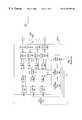
- FIG. 4is a block diagram of a traffic shaper for use in the HDT of the inventive network of FIG. 3;
- FIG. 5shows how broadband traffic is shaped by the traffic shaper of FIG. 4;
- FIG. 6depicts the downstream frame structure emitted by the PON base station in the HDT of the inventive network
- FIG. 7illustrates the operation of the ONU demultiplexer given an example service and traffic mix
- FIG. 8shows how upstream bursts are transmitted by the ONU multiplexer.
- Access to a fiber-based communications networkis typically provided by an access system comprising an HDT joined by fiber optic cable (a fiber feeder) to a plurality of ONUs either by forming individual, respective point-to-point links or in a network topology such as a synchronous optical network (SONET) ring or a PON. Illustrated in FIG. 1 is an ONU 1 connected to an HDT 2 in a PON, wherein a strand of fiber 47 from the HDT is separated by a passive optical splitter (not shown) into a number of fiber umbilicals 38 a,b,c leading to each ONU (of which only one is shown).
- Separate fiberscan be used for transporting optical traffic in the downstream and upstream directions, although bidirectional traffic can be carried by a single fiber using wavelength division multiplexing.
- the ONU 1generally comprises components for transporting downstream data, including a receiver 12 for converting optical data on the fiber umbilical 38 a to a digital electronic signal 13 , which passes through a downstream PON-outstation (PON-OS) 11 followed by a demultiplexer 6 .
- PON-OSPON-outstation
- a number of demultiplexed signal lines 25leave the demultiplexer 6 and enter respective broadband line cards (BLCs) 4 , which typically interface with customer-premises equipment (CPE) 99 via loops of twisted pair drops 3 .
- BLCsbroadband line cards
- CPEcustomer-premises equipment
- the ONU 1also comprises an ONU control processor 5 , which receives downstream control data by virtue of being connected to the downstream PON-OS 11 , and is also connected to the demultiplexer 6 over whose routing map it exerts control.
- the ONU control processor 5further provides a control line 29 to the BLCs.
- the downstream signal line 25enters a demultiplexer 24 which separates incoming traffic according to traffic class, storing any as yet undelivered data inside respective queues 27 .
- the output rate of each queueis controlled by a queue control block 28 receiving instructions on control line 29 .
- the data output by the queues 27is remultiplexed into a sequence reflecting the traffic priority (i.e., high-priority first) by a controllable multiplexer 23 and sent to the CPE 99 in an appropriate format by a broadband hybrid 19 after first passing through a digital modem 22 and a transmitter driver 21 , both under control of the ONU control processor 5 through control line 29 .
- the hybrid 19 of each BLC 4provides a digital upstream signal to a queue structure 31 via a receiver 35 and a digital modem 33 , both of which are controlled by the ONU control processor 5 via control line 29 .
- the queue structure 31may either resemble that formed by the demultiplexer 24 , queues 27 and multiplexer 23 , or it may be a single, very long buffer, under control of the queue control block 28 .
- the output 30 of the queue structure 31 of each BLC 4is fed to a multiplexer 7 , which produces a data stream 17 destined for the HDT 2 .
- the data stream 17passes through an upstream buffer 8 , and subsequently through an upstream PON-OS 9 and an optical transmitter 10 on its way towards the HDT 2 along fiber umbilical 38 a .
- the multiplexer 7 and upstream PON-OS 9are controlled by respective signals from the ONU control processor 5 .
- the HDT 2interfaces with the optical fiber 47 by means of a respective one of a plurality of optoelectronic transceivers 45 .
- PON-BSPON base station
- a significant element of the HDTis a digital switch matrix 44 , typically a high speed ATM switch fabric, which is connected to each PON-BS 40 by an upstream path 42 and a downstream path 41 .
- a queue 43is usually installed in the downstream path between the switch matrix 44 and each PON-BS 40 to temporarily store excess downstream data from the switch matrix 44 until it can be accommodated by the bandwidth of the PON-BS 40 .
- the switch matrix 44exchanges data with an outside “core” network 51 by another plurality of optoelectronic transceivers 50 and respective buffers 43 a leading from the switch matrix 44 . Also connected to the switch matrix 44 are a signalling processor 55 , a control processor 56 and an operation, administration and maintenance (OAM) processor 57 . Control, provisioning and maintenance instructions and responses are communicated by a control line 58 linking the OAM processor 57 to elements in the management layer of the core network 51 .
- OAMoperation, administration and maintenance
- data flowgenerally consists of groups of ATM cells travelling in either direction through the HDT 2 and ONU 1 .
- the upstream and downstream pathshave differing traffic and timing characteristics and can be considered separately.
- data from the core network 51 entering the HDT through transceivers 50may require reformatting of the signalling information associated with each circuit by the signalling processor 55 in order to map the network-side signalling protocols to the access-side signalling protocols, thereby to provide the switch matrix 44 with streams of appropriately formatted ATM cells.
- an ATM cell 200possesses a five-byte header 201 , identifying a virtual circuit and/or virtual port (VC/VP), and a 48-byte payload 202 .
- VC/VPvirtual circuit and/or virtual port
- the subsequent descriptionis simplified by considering only the information carried by the VC.
- the VCimplicitly identifies not only a destination BLC, but also a class of service (BC, CBR or UBR). It is not unusual for multiple VCs and multiple classes of service to be established with the same BLC.
- the switch matrix 44is lightly loaded, i.e., it is fast enough to route all incoming ATM cells as soon as they arrive, a plausible assumption in today's era of 10 Gigabit-per-second (Gbps) switches.
- GbpsGigabit-per-second
- the switch matrix 44routes each cell towards the ONU corresponding to the BLC associated with the VC/VP specified in the header of that cell.
- the actual mapping of VC/VP to physical location of BLCis specified by the control processor 53 .
- the data stream output by the PON-BS 40consists of ATM cells grouped into “subframes” according to their destination ONU, along with address data and control information, which are then fed to the transceiver 45 .
- the subframes destined for different ONUsare concatenated by the PON-BS 40 and form a complete “frame” of 125 microseconds (which is compatible with existing synchronous switched networks).
- the framesare converted into electronic format by the receiver 12 and fed to the PON-OS 13 , which has the responsibility of (a) selecting only the subframes destined for that ONU and disregarding the rest; (b) extracting the control information from the incoming stream and sending it to the ONU control processor 5 ; and (c) sending the remaining ATM cells to the demultiplexer 6 .
- the control informationmay comprise, for example, the VC/VP-to-BLC mapping for control of the demultiplexer 6 , which accordingly routes the cells to the appropriate BLC 4 . Since it is assumed that the capacity of each demultiplexer port is such that the full input bandwidth from the PON could, if necessary, be accommodated by any port, the ONU control processor 5 does not control the output data rate of the demultiplexer 6 .
- the incoming ATM cells 25are then separated according to VC and/or service class by the demultiplexer 24 and inserted into a corresponding queue 27 .
- the demultiplexer 6per se can be implemented such that it is not a choke point, the downstream bandwidth constraints of the BLCs 4 lead to the requirement of buffering within queues 27 .
- the rate at which the queues 27 are emptiedis controlled by the queue control block 28 , which typically bases its decisions on a service class hierarchy, releasing any buffered BC and CBR traffic before sending any UBR traffic.
- the cellsare reassembled by the multiplexer 23 into a cell stream that is formatted by the modem 22 and sent to the CPE 99 through the transmitter driver 21 , hybrid 19 and copper drop 3 .
- data transmitted from the CPE 99is converted into a digital stream 32 of ATM cells by the modem 33 after passing through the hybrid 19 and the receiver 35 .
- the stream 32passes through the queue structure 31 on its way to the multiplexer 7 , where data streams from several BLCs are combined into a single data stream 17 .
- the queue structure 31 within each BLC 4may be a simple ATM cell buffer or may be similar to the combination of the demultiplexer 24 , queues 27 and multiplexer 23 present in the downstream path.
- the stream 17 of ATM cellsis arranged into subframes and transmitted by the upstream PON-OS 9 at a rate that is controlled by the ONU control processor 5 .
- the buffer 8stores excess ATM cells that cannot be sent immediately upon arrival at the upstream PON-OS 9 . (Such buffer was not required in the downstream path, as it was assumed that the output ports of demultiplexer 6 could handle the full PON bandwidth.)
- the ONU control processor 5also manages the queue structure 31 , and receives subscriber-generated control information detected by the multiplexer 7 .
- the ONU control processor 5interprets timing information based on control information in the subframes arriving downstream from the PON-BS. This timing information is generated by a marshalling circuit in the PON-BS 40 , such as that disclosed in draft specification I.983 submitted to the ITU. The net overall effect is that upstream subframes arriving at the HDT are separated by small time spans during which no valid data is transmitted, also known as guard bands.
- the PON-BS 40accepts the subframes containing ATM cells in electronic format from the transceiver 45 , reads any control information that may have been inserted by the upstream PON-OS 9 in the ONU 1 , and sends individual ATM cells to the switch matrix 44 for further routing.
- Cells destined for the core networkpass through queues 43 a and through transceivers 50 after being reformatted into an appropriate format by the signalling processor 55 .
- the control processor 56communicates control information with each PON-BS 40 and with the OAM processor 57 .
- a queue that is too meagre in size to handle the downstream data rates supplied to itcan be supported by additional buffers between the demultiplexer 6 and each line card.
- the conventional system architecturewith respect to traffic flow, results in the installation of a set of large buffers that is complex, dependent on service characteristics and traffic classes, and rife with associated control problems.
- the ONUthus suffers from increased complexity, cost, power consumption and physical size, more frequent failures, while still leaving the system prone to corrupt transmission due to buffer overflow.
- FIG. 3depicts an access system in accordance with the present invention, comprising an HDT 83 connected between a core network 51 and a plurality of ONUs 59 (only one of which is shown) in a PON configuration.
- a SONET ring or a plurality of individual point-to-point linkscan also be used to interconnect the ONUs and HDT.
- a bidirectional optical fiber feeder 47connects the HDT 83 to an optical splitter (not shown), which passively splits/joins a plurality of fiber umbilicals 38 a,b,c leading to respective ONUs.
- the HDT 83comprises a switch matrix 44 connected in a known way to a signalling processor 55 , a control processor 66 and an OAM processor 57 connected by its own control line 58 to the management layer of the core network 51 .
- the control processor 66may pass through the switch matrix before gaining access to the OAM processor 57 .
- the switch matrixis preferably a routing switch capable of handling ATM cells at a high rate (e.g., 10 Gbps), and is connected to the core network 51 through a plurality of transceivers 50 .
- the switch matrix 44is also connected to a plurality of “traffic shapers” 79 , of which there is one for each access transport system (in this case, one per PON).
- the purpose of the traffic shapersis primarily to control the rate of downstream data flow on each VC in order to prevent congestion from taking place at downstream choke points, while maintaining efficient usage of the available bandwidth on the multiplexed transmission path from the HDT to multiple ONUs, in this case shown as a PON.
- Each traffic shaper 79is connected to a PON-BS 40 and to a transceiver 39 for interfacing with the optical fiber feeder leading to the ONUs on that PON.
- the traffic shapers 79are connected to the control processor 66 in the HDT 83 by a respective set of control lines 7951 , which provide bandwidth strobes, VC-to-service maps and other relevant information to various parts of each traffic shaper, as described below. Again, these links may be established by passing through the switch matrix 44 .
- the switch matrix 44is lightly loaded (i.e, that it does not cause congestion)
- incoming packetsneed not be buffered.
- the downstream packets headed for the traffic shapers 79 or the upstream packets headed for the transceivers 50normally do need to be buffered by respective queues 43 , 43 a .
- the input stage of the traffic shaper 79is sufficiently fast, then it can absorb packets as fast as they can be output by the switch matrix 44 , obviating the need for buffering at the corresponding queue 43 .
- buffersmay be required in both directions of traffic flow at each of its ports.
- each transceiver 39may consist of a separate optoelectronic transmitter and receiver.
- Another embodimentmight feature a single PON-BS that amalgamates upstream and downstream functionality in a single block.
- the ONUs 59 and BLCs 60 employed in the inventive access systemdiffer in that the memory requirements and complexity are considerably reduced.
- the inventive ONU 59comprises, as in the prior art, an optical receiver 12 , a downstream PON-OS 11 and a demultiplexer 6 in its downstream path leading to a plurality of BLCs 60 via respective signal lines 62 .
- the ONU 59also comprises a multiplexer 7 in the upstream path, whose output passes through a minimal buffer 72 on its way to being transmitted by an upstream PON-OS 9 and optically converted in the usual way by a transmitter 10 .
- the purpose of buffer 72is to store the upstream traffic from the subscriber until the upstream PON-OS 9 is permitted to transmit in the upstream direction in accordance with a time-division multiple access scheme.
- the required size of buffer 72will depend on the speed with which an upstream bandwidth request can be negotiated once the buffer begins to fill. This is a function of the delay of the upstream bandwidth allocation process, but is independent of the transaction size. Buffer 72 is always needed but may be internal to the upstream PON-OS 9 .
- an ONU control processor 76for reading control information from the downstream PON-OS 11 and providing a routing map to the demultiplexer 6 .
- the ONU control processor 76also supplies a control signal 75 to each BLC 60 , as well as burst timing information to the upstream PON-OS 9 .
- the link between the downstream PON-OS 9 and the ONU control processor 76may be physical, as illustrated in FIG. 3, or the ONU control processor 76 may simply monitor cells at the output of the downstream PON-OS 9 in search of those which are destined for it.
- each ONU 59the line interfacing is performed by a plurality of BLCs 60 , each comprising a broadband hybrid 19 for connection to a copper twisted pair leading to a respective CPE 99 .
- each BLC 60accepts a respective one of the signal lines 62 from the demultiplexer 6 , leading to a minimal downstream queue 85 connected to a digital modem 22 , a transmitter driver 21 and the broadband hybrid 19 .
- the queue 85is controlled by a control block 78 based on information contained in the control signal 75 received from the ONU control processor 76 .
- the queue 85 in each line cardneed only accommodate enough ATM cells to account for so-called multiplexing jitter, which occurs when a certain number of cells arrive at the queue (from the demultiplexer 6 ) at a high bit rate but can only leave the queue 85 at a significantly lower bit rate.
- the inventive systemcan limit the number of cells to be stored by the queue 85 to the number of cells contained in a single frame. This value is several orders of magnitude less than the storage capacity required in the prior art and is independent of the size of a requested transfer.
- the hybrid 19 in each BLC 60provides an upstream signal 36 to a receiver 35 , which is connected to a digital modem 33 , followed by a minimal upstream queue 77 .
- the queue 77is also controlled by the queue control block 78 , and provides an upstream signal 74 to the multiplexer 7 .
- the form of the upstream queue 77may be the same as in the prior art, i.e., separated into parallel queues for each traffic class and recombined by a demultiplexer.
- the upstream queue 77may be a simple “first in, first out” buffer.
- buffer 77is much smaller than the queue 31 in the prior art, since the rate of upstream data trasmitted by the CPE would preferably be controlled by a centralized control processor in the HDT.
- traffic shaping in the downstream directioncan be relegated to a single component or software program in conjunction with the control processor 66
- the distributed nature of the upstream transmission pathcalls for a distributed traffic shaping control mechanism involving the control processor 59 and each CPE 99 .
- the present inventionapplies to the control of traffic in either the upstream or downstream direction, or both.
- the traffic shaper 79comprises a demultiplexer 7901 for routing incoming downstream ATM cells 7933 according to a mapping of VC/VP versus traffic class supplied by the HDT control processor 66 via control line 7973 .
- the output of the demultiplexer 7901is thus separated into three streams 7903 - 7905 according to the three different service classes ( 7903 for BC, 7904 for CBR, 7905 for UBR).
- the three streams 7903 - 7905 of ATM cellspass through an arrangement of other components, which implement a series of service-class-dependent shaping and prioritization functions, alongside recombination functions, before exiting the traffic shaper as a single stream 7934 of ATM cells ready to be grouped into subframes by the PON-BS 40 .
- the BC stream 7903is connected to the input of a demultiplexer 7930 , which extracts a plurality of BC streams 7931 from the BC stream 7903 .
- Each separate BC stream 7931respectively enters a buffer 7906 at whose output is repectively located a simple shaper 7907 .
- the simple shapers (or “pacers”) 7907are components that control the respective rates at which cells leave buffers 7906 , as controlled by respective bandwidth strobes 7926 from the control processor 66 .
- the control processor 66itself receives provisioning commands indicating the bandwidth of the individual BC channels from a services provisioning manager (SPM) in the core network.
- SPMservices provisioning manager
- a priority gateis a component which, in addition to having a primary input port P, comprises a secondary input port S and an output port O and exerts the following input-output relationship: “any cells present at the primary input P are directly routed to the output O. If no cells are present at the primary input P, then cells present at the secondary input S appear at the output O.” That is to say, traffic at the primary input P has priority over traffic at the secondary input S.
- the CBR stream 7904enters a demultiplexer 7911 , where it is demultiplexed on a per-VC or per-VP basis, depending on the required traffic shaping characteristics, producing individual CBR streams 7912 .
- the individual streams 7912are connected to respective buffers 7913 , whose outputs are provided to a multiplexer 7915 at a rate controlled by respective simple shapers 7914 .
- These simple shapers 7914respectively modify the individual buffer output rates according to bandwidth strobes 7927 received from the control processor 66 .
- the output of multiplexer 7915is connected to the secondary input S of priority gate 7908 via a queue 7916 for storing excess cells that are not immediately accepted by the priority gate 7908 .
- the UBR stream 7905As for the UBR stream 7905 , it is separated by a demultiplexer 7917 on a per-service basis (as there may be more than one service associated with a single copper drop).
- the individual streamsare buffered by respective queues 7918 , which are then regrouped on a per-drop basis by a set of “fair-share” multiplexers 7919 .
- These componentsallot an equal number of packets in their respective output streams to each input, while ignoring inputs that do not present any data, i.e., the multiplexers 7919 do not consider UBR circuits that are unoccupied.
- each fair-share multiplexer 7919is thus a stream of low-priority cells corresponding to one BLC, which is then buffered by a respective queue 7920 whose output rate is controlled by a respective simple shaper 7921 .
- the simple shapers 7921are under the influence of respective bandwidth strobes 7928 from the control processor 66 .
- the streams of cells exiting the buffers 7920are optionally buffered by respective queues 7996 whose outputs are then regrouped by another fair-share multiplexer 7922 .
- the output of the fair-share multiplexer 7922is preferably buffered by a queue 7923 whose output cell rate is determined by a shaper 7924 controlled by a bandwidth strobe 7929 from the control processor 66 .
- fair-share multiplexer 7922is preferably one which devotes equal amounts of output bandwidth to all of its inputs, it can implement other “fair-share” schemes, such as one which measures and equalizes the level to which the buffers 7920 are filled.
- the output of buffer 7923passes through a final buffering stage at a queue 7925 whose output is connected to the secondary input S of another priority gate 7909 .
- shapers 7921may receive bandwidth strobes calculable from the bandwidth strobes 7928 and from a “buffer full” signal that is fed from the buffer 7925 and which indicates the level to which buffer 7925 is occupied.
- priority gates 7908 , 1909are connected in such a way that the output port O of priority gate 7908 feeds the primary input port P of priority gate 7909 .
- Thisestablishes a hierarchy, whereby BC traffic has priority over CBR traffic (because of priority gate 7908 ), which has priority over UBR traffic (because of priority gate 7909 ).
- the data at the output O of priority gate 7909forms a sequence of ATM cells that are subsequently fed to the PON-BS.
- demultiplexer ports on demultiplexers 7930 , 7911 , 7917 and their respective sets of output buffers 7906 , 7913 , 7918are themselves not choke points, i.e., their instantaneous bandwidth handling capacity is taken to be sufficiently high. If this is not the case and there are some bandwidth handling constraints (e.g., through having chosen a power-efficient buffering technology for one or more sets of buffers), then it is necessary to introduce further buffering between the input demultiplexer 7901 and the next stage of demultiplexing.
- a queue 43may be installed directly at the output of the switch matrix 44 .
- the structure of the inventive traffic shaperhas been described with reference to actual physical blocks, it is to be understood that its realization may be radically different.
- the desired remapping of cells from an input sequence to an output sequencecould be achieved by implementing the traffic shaper as a very large and fast random access memory which is accessed and controlled by a traffic shaping control processor.
- This processormay be separate from the control processor 66 in the HDT 83 . Irrespective of the chosen implementation, the functionality of the traffic shaper remains the same, and is set forth hereunder in further detail.
- the input sequence 7933 of ATM cellsis remapped into the output sequence 7934 of ATM cells, based on control information supplied by the control processor.
- the demultiplexer 7901reads the VC/VP information in the header of each input cell and then consults a mapping supplied by the control processor 66 via control line 7973 in order to determine the traffic class, i.e., BC, CBR or UBR, of the particular VC/VP.
- FIG. 5shows the detailed operation of the outlined region 7950 of FIG. 4, including two buffers 7906 a,b accepting respective input streams 7931 a,b , along with multiplexer 7932 producing an output stream 7941 , and priority gate 7908 producing an output stream 7942 .
- the contents of broadcast streams 7931 a,bhave been respectively identified as numbers (1,2,3,4) and (5,6) thereby to indicate corresponding broadcast services delivered in valid data cells; unused gaps spanning the duration of one cell are represented as blank cells.
- Simple shapers 7907 a,baccept bandwidth strobes 7926 a,b , from the control processor and control the output rate of buffers 7906 a,b connected to multiplexer 7932 .
- the bandwidth strobes 7926 a,bgenerate substantially even buffer output rates to the multiplexer 7932 .
- the two sets of strobesare non-overlapping in time, and the residual gaps can be used by the priority gate 7908 to insert cells of lower priority (CBR) data 7943 into output data stream 7942 , where the low priority data is labelled “L”.
- CBRlower priority
- the broadcast data 7941 output as a result of the rates indicated by broadcast bandwidth strobes 7926 a,b (and more if needed)is the highest priority type of data that can be transmitted by the fiber feeder across the PON.
- a controllable number and selection among the available broadcast channelsis mapped to broadcast “bearers” which deliver the broadcast services to the individual subscribers.
- a services provisioning manager (SPM) in the core networkusually manages the channel-to-bearer mapping associated with each BLC, which is delivered to the corresponding ONU via a downstream control channel, to be discussed later.
- a subscriberwishes to access an excessive number of broadcast bearers, then congestion occurs at the copper drop without any corresponding bandwidth constriction at the HDT.
- video channelssay, 100
- a subscriberconnected to the ONU via a copper link which has a maximum capacity of, say, 20 Mbps, may try to access (watch) an excessive number of those channels simultaneously to feed multiple TV sets (e.g., 10 bearers of individual 3 Mbps channels for a total of 30 Mbps).
- the SPM and a service interface at the CPEwill negotiate a data rate. (Generally, the higher the data rate, the greater the cost to the subscriber.) After agreeing to a particular rate that is to be delivered to the service interface, the SPM then discloses this rate to the control processor, which then controls the CBR buffers 7913 in FIG. 4 by supplying complementary bandwidth strobes to the simple shapers 7914 . Again, the bandwidth strobes will produce an even flow of data, and the control processor need not concern itself with congestion, as the SPM was well aware of the bandwidth limitations due to broadcast traffic when negotiating the CBR bandwidth in the first place.
- each fair-share multiplexer 7919provides an even distribution among UBR services on its corresponding drop, providing a stream of UBR traffic to the corresponding queue 7920 .
- the control processor 66exerts control over simple shapers 7921 in order to allocate the residual bandwidth on each drop to the UBR traffic cells in buffers 7921 after accounting for the already established BC and CBR circuits.
- Control of simple shapers 7921is effected on a per-BLC (i.e., per drop) basis, to ensure, for example, that a large available residual bandwidth on the PON does not carry a large transaction (waiting in one of the buffers 7920 ) at a rate that cannot be handled by the subscriber's drop.
- the UBR traffic on each droppasses through the fair-share multiplexer 7922 , where each drop having traffic waiting to be delivered is given a fair share of the output bandwidth of the multiplexer 7922 .
- the resultant streamis fed to the buffer 7923 , which outputs cells to buffer 7925 at a rate corresponding to the residual bandwidth available on the PON, as controlled by the bandwidth strobe 7929 fed to simple shaper 7924 .
- buffer 7923may be bypassed and the residual bandwidth on the PON can be controlled jointly with the residual bandwidth on each drop.
- control processor 66calculating a bandwidth strobe for the simple shapers 7921 which would be based not only on the original (per-drop) bandwidth strobe 7928 but also on a “buffer full” signal fed from the buffer 7925 and indicating its occupancy level.
- mapping of the input sequence 7933 of ATM cells to an output sequence 7934 of ATM cells by the traffic shapermust satisfy a set of inequalities comprising parameters that characterize the different bandwidth limitations in the system. Specifically, one may define:
- N ONUnumber of ONUs in the PON
- N BLC (i)number of BLCs on the ith ONU
- N BC (i,j)number of BC bearers used by the jth BLC of the ith ONU
- N CBR (i,j)number of CBR circuits established with the jth BLC of the ith ONU
- N UBR (i,j)number of UBR services delivered to the jth BLC of the ith ONU
- broadcast cells from each channel being accessed by multiple subscribersare reproduced at the ONU according to the address map of the demultiplexer 6 .
- bw CBR (i,j,k)bandwidth of the kth CBR circuit established with the jth BLC of the ith ONU
- bw UBR (i,j,k)bandwidth of the kth UBR service delivered to the jth BLC of the ith ONU
- the above variablesmust be manipulated in such a way that the sum of the bandwidths of all the services entering all the ONUs in the PON does not exceed “E”, both as a long-term average or as a short-term peak, other than what can be handled by buffers (e.g., queue 85 in each BLC) used to counter multiplexing jitter.
- bufferse.g., queue 85 in each BLC
- the bandwidth delivered to each subscriber, including all CBR, UBR and broadcast servicesmust not exceed “A”, again both in the long term and in the short term.
- top priorityis given to broadcast traffic, then to CBR traffic that has already been provisioned, and then to UBR traffic.
- T PON BCis the total PON bandwidth occupied by the plurality of broadcast channels made available to all subscribers
- T DROP BC (i,j)is the total drop bandwidth occupied by the plurality of broadcast bearers being used by subscriber j on ONU i
- T PON CBRis the total PON bandwidth occupied by all CBR circuits
- T DROP CBR (i,j)is the total drop bandwidth occupied by the plurality of CBR circuits established with subscriber j on ONU i.
- inequality ⁇ 1>will always hold, and the control processor 66 will instruct simple shapers 7907 to provide a non-overlapping, even flow of output cells.
- the attachment of this bearer to a broadcast channelis authenticated in a central location, either by the OAM processor 57 , the control processor 66 , the SPM or alternatively by a separate Broadcast Control Unit (BCU, not shown).
- the central location processorwill thus grant the request if inequality ⁇ 1a> can remain satisfied. If there is very little CBR and UBR traffic on the drop, the request for a bearer is granted without consequence.
- inequality ⁇ 1a>dictates that there is a capacity for a new bearer, but the low-bandwidth (e.g., 20 Mbps) drop is busy with CBR and UBR traffic, then granting of a new bearer will require that the bandwidth used by (lower priority) CBR and UBR traffic be reduced.
- the low-bandwidthe.g. 20 Mbps
- inequality ⁇ 1a>reveals that a new bearer of BC traffic can be allocated to the drop j on ONU i, but that the CBR and UBR traffic on this link do not leave enough room for the new BC bearer. This leads to a desired value for T DROP BC (i,j), which is substituted into inequality ⁇ 2a>. If inequality ⁇ 2a> remains true, then it is possible to meet the request for a new bearer simply by reducing the UBR services delivered to the drop, without influencing the already-provisioned CBR circuits.
- the bandwidth strobe 7928 supplied by the control processor 66 to the one simple shaper 7921 handling UBR traffic for drop j on ONU iis made sparser to the degree required that inequality ⁇ 3a> remain satisfied.
- the rates of the other bandwidth strobes 7928are fractionally increased, since the total UBR bandwidth delivered across the PON remains the same (bandwidth strobe 7929 delivered to simple shaper 7924 remains unchanged) but this bandwidth is distributed among fewer contenders.
- the first stepis to halt the UBR services for drop j on ONU i by throttling the simple shaper 7921 in charge of this drop via the corresponding one of the bandwidth strobes 7928 .
- the CBR circuits to be cancelledare throttled via the appropriate bandwidth strobes 7927 controlling the egress rates of simple shapers 7914 . From inequality ⁇ 3> it is found that the liberation of one or more CBR circuits on a given drop increases the available UBR bandwidth on the PON. Therefore, bandwidth strobe 7929 controlling simple shaper 7924 will command a higher output rate for its associated buffer 7923 .
- inequality ⁇ 3a>is solved for all other drops, and it may turn out that the UBR services on one or more drops will be able to benefit from the added PON bandwidth, thereby increasing the egress rate of those buffers 7920 not handling UBR service on drop j on ONU i.
- UBR servicescan be delivered to the drop.
- the data rate that can be imparted to UBR trafficis therefore determined by the simultaneous solution of inequalities ⁇ 2> and ⁇ 3>.
- a change in available UBR bandwidth across the PONis reflected in the output rate of buffer 7923 , controlled by simple shaper 7924 via bandwidth strobe 7929 , whereas a change in UBR bandwidth used on a given drop is reflected in the output rate of the corresponding buffer 7920 .
- the resultant sequence of ATM cells 7934is formatted by the PON-BS 40 for transmission across the PON or other suitable transmission system that is used to interconnect the HDT to the outlying ONUs, e.g., an arrangement of point-to-point links, add-drop chains or SONET rings.
- the PON-BS 40sorts the incoming cells according to each cell's destination ONU and traffic class (both of which can be determined from the VC/VP in the cell's header), groups the sorted cells into subframes, and concatenates the subframes to form frames which are typically of duration 125 microseconds, thereby to conform to current ATM standards and emerging PON standards, and also to permit carriage of multiplexed pulse-code-modulation (PCM) voice within the access infrastructure.
- PCMpulse-code-modulation
- the PON-BS 40is told by the control processor 66 how to distribute the available downstream fiber bandwidth among the various subtending ONUS.
- the resulting framescreate a set of parallel, dynamically sizable “pipes” of data whose contents have been carefully selected so as to flow freely through the various downstream choke points.
- FIG. 6illustrates a series of downstream frames F 1 to F 5 formed in this manner.
- Each frameis identical in length and is preferably divided into N ONU +2 subframes, although the subframes need not necessarily be of the same size within the frame or across frames.
- frame F 3is subdivided into seven subframes SF 0 to SF 6 , among which subframe SF 0 is a broadcast subframe, subframes SF 1 to SF 5 are destined for respective ONUs and subframe SF 6 is a spare capacity subframe.
- the relative size of each subframeis determined by the overall bandwidth requirement for broadcast traffic and the relative bandwidth demands of each individual ONU.
- traffic cells forming part of frame F 3 in FIG. 6have each been given a letter (corresponding to the traffic class) and a number (corresponding to the VC or VP).
- the broadcast traffic cells carrying channels B 1 ,B 2 , . . .have been grouped into broadcast subframe SF 0 , to which is also appended an address channel 601 and a control channel 602 .
- the address and control channels 601 , 602establish the downstream control link between the HDT and the subtending ONUs. It is to be understood that the address and control channels may themselves be ATM cells which identify (in their respective headers) the destination ONUs, or a specific component in the destination ONUs.
- the address and control channels 601 , 602can optionally identify all ONUs on the PON as destination ONUs.
- Subframes SF 1 to SF 5each comprise traffic cells carrying CBR and UBR traffic hich are destined for a single ONU.
- Subframe SF 3has been expanded to show traffic cells carrying CBR circuits C 1 ,C 2 , . . . and UBR services U 1 ,U 2 , . . . Again, there is shown the preferable arrangement of an ONU address and synchronization channel 701 (indicating the destination ONU), as well as an ONU control channel 702 .
- each subtending ONUread only two subframes, SF 0 and the one destined for that ONU
- the subframesthemselves may comprise an unused portion that represents spare downstream capacity on the PON. This may be used in conjunction with, or as a replacement for, the spare capacity subframe SF 6 shown in FIG. 6 .
- the control information for each subframemay be grouped together in a separate subframe which is destined for all downstream ONUs.
- Another variationconsists of eliminating the broadcast subframe SF 0 and inserting a fraction of the broadcast cells in each subframe.
- This “embedded broadcast” approachrequires that each subtending ONU read all the subframes, extracting all the cells from one subframe and only the broadcast cells from all the other subframes.
- the transmission of downstream and upstream datamay occur in alternating bursts, the duty cycle of which determines the percentage of available bandwidth that is used in each direction.
- FIG. 7serves to illustrate an example mode of operation of the downstream PON-OS 11 and demultiplexer 6 at the ONU.
- the downstream PON-OS 11reads the ONU address channel of each subframe. If the subframe is a broadcast subframe, then the all cells in the subframe are sent to the demultiplexer 6 . If the subframe is not a broadcast subframe but is destined for that ONU, then its cells are sent to the multiplexer 6 ; otherwise its contents are ignored. Therefore, the demultiplexer 6 receives an intermittent stream 802 of ATM cells. Information in the control channels of the two accepted subframes is fed to the ONU control processor ( 76 in FIG. 3 ).
- the demultiplexer 6receives the intermittent cells and outputs streams 803 - 806 of ATM cells destined for respective line cards according to a mapping that is supplied by the ONU control processor based on information in the downstream control channel of the broadcast and non-broadcast subframes.
- a routing table 807 that associates each combination of virtual circuit and traffic class to a specific line cardis contained in the demultiplexer 6 .
- This mappingdepends on the bandwidth requirements and service requests of the end user and therefore changes with time. (For example, this mapping determines the broadcast channels carried by broadcast bearers to a particular subscriber, as discussed earlier.)
- the mapping 807can be updated by supplying appropriate mapping instructions from the control processor 66 via the control channel of the subframes to the ONU control processor 76 .
- An example mapping 807is shown in FIG. 7 :
- broadcast cellsare routed to more than one ONU and, within each ONU, are often routed to more than one one line card. According to the above mapping, broadcast cells B 1 , B 2 and B 3 are to be routed to more than one BLC, which requires cell replication at the demultiplexer 6 .
- the queue 85 accepting a stream of ATM cellsneed accommodate enough cells to account for multiplexing jitter.
- This phenomenonis a consequence of the nature of the transmission process, rather than having to do with the characteristics of the transmitted traffic.
- multiplexing jitterarises when cells arrive at the queue in bursts during which data arrives at a peak bit rate but the arriving cells leave the queue at a substantially continuous, but lower bit rate.
- the queues 85are relatively small compared to those in prior art systems.
- the size of the queueis independent of the characteristics of the throughput traffic such as the size of a requested file transfer or transaction.
- the downstream PON-OS 11 and ONU control processor 76may communicate with the CPE 99 using specially addressed ATM cells, via dedicated links, or using particular modulating techniques.
- ATM cells arriving in an analog format from the CPE 99are delivered to the queue 77 in digital format in one of many known ways via the hybrid 19 , the receiver 35 and the digital modem 33 .
- the queue 77feeds an output stream 74 of ATM cells into the ONU multiplexer 7 .
- the upstream cellsare multiplexed as they arrive at the multiplexer 7 and are fed through another buffer 72 to the upstream PON-OS 9 .
- the upstream PON-OS 9assembles a group of upstream cells into a subframe, and waits for a synchronization signal from the ONU control processor 76 prior to upstream transmission.
- the actual number of cells in a subframe, as well as the timing informationis derived from the information contained in the control channel in the downstream subframes.
- a marshalling algorithmaccordinging to ITU draft specification I.983, for example
- the resultant sequence of subframesis shown in FIG. 8 as forming a “train” 901 of subframes separated by guard bands which contain no valid data.
- the appropriate transceiver 39Upon arrival of the slightly “gapped” train of subframes at the HDT, the appropriate transceiver 39 converts the optical signal into an electronic one.
- the PON-BS 40ignores the guard bands, strips the control and address information from the subframes and produces a stream of ATM cells travelling towards the ATM switch matrix 44 . If the switch matrix 44 is lightly loaded, then the data is immediately routed by the switch matrix 44 towards its destination in the core network.
- An important scenario to consideris that of an ONU that has been allocated a fixed upstream data rate, i.e., the number of cells in its upstream subframe is limited.
- a new service interface on that ONUwishes to transmit upstream data
- at least one BLC in the ONUmay actually be attempting to transmit data at a higher rate than that which is available to the ONU.
- a certain amount of traffic shapingis necessary to reallocate the upstream bandwidth on the PON, and this can be done without introducing any new hardware.
- each queue control block 78is interrupted when the upstream queues 72 , 77 are filling at a higher rate than usual, and subsequently to request additional upstream PON bandwidth for its ONU by submitting such request to the PON-BS 40 in the HDT, which further relays these demands to the control processor 66 (or to the separate traffic shaping processor).
- the processor responsible for the upstream traffic shapingevaluates whether the requests can be met by applying a series of inequalities similar to ⁇ 1> to ⁇ 3a> above, but with upstream parameters. In many cases, the processor will allow the granting of an increased quantity of bandwidth, but which is less than that requested. If the new amount of bandwidth is indeed inferior to the requested amount, then the control processor signals to certain ones of the CPEs (via the downstream control channels and appropriate BLCs) that bandwidth throttling is required in the CPE, i.e., that the data rate of upstream UBR circuits is to be reduced at the source.
- control processor 66Since the control processor 66 has visibility into the bandwidth usage across the entire PON, it may also recognize that certain ONUs or BLCs are not using their full upstream bandwidth, and may increase the number of cells in the upstream subframes associated with the busier ONUs. The control processor 66 will make this information available to the higher layers of the core network 51 .
- buffer 72 in the ONU and buffers 77 in the overly demanding BLCswill continue to fill at a rate equal to the difference between the requested upstream capacity and the summation of the upstream capacities of the BLCs.
- the delay incurred due to the bandwidth reallocation procedureis a controllable design parameter of the ONU transmission path and HDT control processor 66 , comprising the summation of the delays through these components. Practical designs can be realized with a total delay of approximately 2 to 5 milliseconds.
- each line card instantaneously requesting 2 Mbps from an initial idle conditionwould require the storage of 10,000 bits (equal to 1.2 kilobytes, or approximately 25 ATM cells) in its upstream path.
- the ONU queue 72 and the individual BLC queues 77are therefore required to provide storage capacity of 1.2 kilobytes per line card.
- the queues 77can be dispensed with if there is enough storage capacity in the upstream ONU queue 72 to handle about a kilobyte of data per attached line card.
Landscapes
- Engineering & Computer Science (AREA)
- Computer Networks & Wireless Communication (AREA)
- Signal Processing (AREA)
- Quality & Reliability (AREA)
- Data Exchanges In Wide-Area Networks (AREA)
- Small-Scale Networks (AREA)
Abstract
Description


| B1, B2, B3, C4 | routed to | ||
| C1 and U1 | routed to | ||
| B1, B4, C2, C3, U2, U4 | routed to | ||
| B2, B3, U3 | routed to | ||
Claims (38)
Priority Applications (4)
| Application Number | Priority Date | Filing Date | Title |
|---|---|---|---|
| US09/084,370US6229788B1 (en) | 1998-05-27 | 1998-05-27 | Method and apparatus for traffic shaping in a broadband fiber-based access system |
| CA002272978ACA2272978C (en) | 1998-05-27 | 1999-05-20 | Novel method and apparatus for traffic shaping in a broadband fiber-based access system |
| DE69934165TDE69934165T2 (en) | 1998-05-27 | 1999-05-27 | New method and apparatus for traffic shaping in a fiber based broadband connection system |
| EP99304110AEP0961522B1 (en) | 1998-05-27 | 1999-05-27 | Novel method and apparatus for traffic shaping in a broadband fiber-based access system |
Applications Claiming Priority (1)
| Application Number | Priority Date | Filing Date | Title |
|---|---|---|---|
| US09/084,370US6229788B1 (en) | 1998-05-27 | 1998-05-27 | Method and apparatus for traffic shaping in a broadband fiber-based access system |
Publications (1)
| Publication Number | Publication Date |
|---|---|
| US6229788B1true US6229788B1 (en) | 2001-05-08 |
Family
ID=22184528
Family Applications (1)
| Application Number | Title | Priority Date | Filing Date |
|---|---|---|---|
| US09/084,370Expired - LifetimeUS6229788B1 (en) | 1998-05-27 | 1998-05-27 | Method and apparatus for traffic shaping in a broadband fiber-based access system |
Country Status (4)
| Country | Link |
|---|---|
| US (1) | US6229788B1 (en) |
| EP (1) | EP0961522B1 (en) |
| CA (1) | CA2272978C (en) |
| DE (1) | DE69934165T2 (en) |
Cited By (83)
| Publication number | Priority date | Publication date | Assignee | Title |
|---|---|---|---|---|
| US20020036984A1 (en)* | 2000-06-02 | 2002-03-28 | Fabio Chiussi | Method and apparatus for guaranteeing data transfer rates and enforcing conformance with traffic profiles in a packet network |
| US20020083316A1 (en)* | 2000-10-13 | 2002-06-27 | Scott Platenberg | Boot procedure for optical tranceiver nodes in a free-space optical communication network |
| US6452935B1 (en)* | 1998-11-25 | 2002-09-17 | Sony Corporation | Stream allocation in home networks |
| US6498667B1 (en)* | 1999-09-10 | 2002-12-24 | Quantum Bridge Communications, Inc. | Method and system for packet transmission over passive optical network |
| US20020196499A1 (en)* | 2001-06-25 | 2002-12-26 | Jeroen Wellen | Method and system for multiplexed optical information transport |
| US20030053170A1 (en)* | 2001-09-17 | 2003-03-20 | Levinson Frank H. | Optoelectronic device capable of participating in in-band traffic |
| US6538989B1 (en)* | 1997-09-09 | 2003-03-25 | British Telecommunications Public Limited Company | Packet network |
| US6549514B1 (en)* | 1998-07-07 | 2003-04-15 | Nokia Corporation | Method and apparatus for shaping traffice for a SIMA network |
| US20030099245A1 (en)* | 2001-11-29 | 2003-05-29 | Yong-Hoe Kim | Host digital terminal |
| US6594304B2 (en)* | 1998-10-30 | 2003-07-15 | Broadcom Corporation | Adaptive configurable class-A/class-B transmit DAC for transceiver emission and power consumption control |
| US20030140353A1 (en)* | 1999-11-08 | 2003-07-24 | Qwest Communications International Inc. | Digital headend and full service network for distribution video and audio programming |
| US20030152389A1 (en)* | 2001-12-14 | 2003-08-14 | Broadcom Corporation | Filtering and forwarding frames at an optical line terminal |
| US6614759B1 (en)* | 1999-12-27 | 2003-09-02 | Electronics And Telecommunications Research Institute | ONU function processing apparatus in ATM-PON system |
| US6633541B1 (en)* | 1999-05-21 | 2003-10-14 | Fujitsu Limited | Ascending transmission speed controlling method and communication system in ATM-PON system |
| US20040042446A1 (en)* | 2002-05-31 | 2004-03-04 | Koch Christopher D. | Maintaining routing information in a passive optical network |
| US6707789B1 (en)* | 1998-12-18 | 2004-03-16 | At&T Corp. | Flexible SONET ring with integrated cross-connect system |
| US6707825B1 (en)* | 1998-12-08 | 2004-03-16 | Salix Technologies, Inc. | Signal processing system |
| US6721797B1 (en)* | 2000-05-16 | 2004-04-13 | Lucent Technologies Inc. | Partial back pressure (PBP) transmission technique for ATM-PON using rate controllers to reduce a maximum output rate from a peak rate to a controlled rate |
| US20040071389A1 (en)* | 2002-09-13 | 2004-04-15 | Hofmeister Rudolf J. | Optical and electrical channel feedback in optical transceiver module |
| US20040076113A1 (en)* | 2002-06-25 | 2004-04-22 | Aronson Lewis B. | Transceiver module and integrated circuit with multi-rate eye openers and bypass |
| WO2004034731A1 (en)* | 2002-10-10 | 2004-04-22 | Foursticks Pty Ltd | Traffic shaping improvement |
| US20040090914A1 (en)* | 2001-03-07 | 2004-05-13 | Briscoe Robert J | Communications network |
| US20040091005A1 (en)* | 2002-11-08 | 2004-05-13 | Hofmeister Ruldolf J. | Temperature and jitter compensation controller circuit and method for fiber optics device |
| US20040117426A1 (en)* | 2001-04-19 | 2004-06-17 | Steven Rudkin | Communications network |
| US6757251B1 (en)* | 1999-06-17 | 2004-06-29 | Nec Corporation | Optical line termination, passive optical network system and method of dynamically controlling an upstream band |
| US20040133920A1 (en)* | 2002-12-18 | 2004-07-08 | Yongtae Kim | Digital broadcast system in passive optical network |
| US20040179471A1 (en)* | 2001-03-07 | 2004-09-16 | Adisak Mekkittikul | Bi-directional flow-switched ring |
| US20040184402A1 (en)* | 2003-03-20 | 2004-09-23 | Alicherry Mansoor Ali Khan | Low latency shared data path allocation |
| US20040208593A1 (en)* | 2001-12-14 | 2004-10-21 | Bloom Scott Harris | Optical amplifiers in a free space laser communication system |
| US6826150B1 (en)* | 2000-04-30 | 2004-11-30 | Dipankar Bhattacharya | Distriburted QoS policing system and method |
| US20050018681A1 (en)* | 2002-05-09 | 2005-01-27 | Optical Solutions, Inc. | Network address assignment in a passive optical network |
| US20050047415A1 (en)* | 2003-08-28 | 2005-03-03 | Radhakrishna Channegowda | Data traffic manager and method therefor |
| US6865149B1 (en) | 2000-03-03 | 2005-03-08 | Luminous Networks, Inc. | Dynamically allocated ring protection and restoration technique |
| US20050111501A1 (en)* | 2002-02-12 | 2005-05-26 | Yew-Tai Chieng | Systems, devices and methods for temperature-based control of laser performance |
| US20050111845A1 (en)* | 2002-06-25 | 2005-05-26 | Stephen Nelson | Apparatus, system and methods for modifying operating characteristics of optoelectronic devices |
| US20050125574A1 (en)* | 2003-12-05 | 2005-06-09 | Foster Joseph E. | Remapping routing information entries in an expander |
| US20050127402A1 (en)* | 2003-12-15 | 2005-06-16 | Dybsetter Gerald L. | Configurable input/output terminals |
| US20050169585A1 (en)* | 2002-06-25 | 2005-08-04 | Aronson Lewis B. | XFP transceiver with 8.5G CDR bypass |
| US20050174938A1 (en)* | 2001-07-20 | 2005-08-11 | Richardson John W. | Dynamic traffic bandwidth management system and method for a communication network |
| US20050213976A1 (en)* | 2004-03-25 | 2005-09-29 | Wellen Jeroen S | Method, apparatus and system for the communication of services in an optical access network |
| US20050232635A1 (en)* | 2004-04-14 | 2005-10-20 | Finisar Corporation | Network data transmission and diagnostic methods using out-of-band data |
| US6958978B1 (en)* | 2001-06-25 | 2005-10-25 | Nortel Networks Limited | Differentiated services in packet-switched networks |
| US20050249497A1 (en)* | 2002-09-13 | 2005-11-10 | Onn Haran | Methods for dynamic bandwidth allocation and queue management in ethernet passive optical networks |
| US20060002711A1 (en)* | 2004-07-02 | 2006-01-05 | Finisar Corporation | Filtering digital diagnostics information in an optical transceiver prior to reporting to host |
| US20060002712A1 (en)* | 2004-07-02 | 2006-01-05 | Finisar Corporation | Calibration of digital diagnostics information in an optical transceiver prior to reporting to host |
| US20060149854A1 (en)* | 2002-01-31 | 2006-07-06 | Steven Rudkin | Network service selection |
| US7110422B1 (en) | 2002-01-29 | 2006-09-19 | At&T Corporation | Method and apparatus for managing voice call quality over packet networks |
| US20060275036A1 (en)* | 2005-06-06 | 2006-12-07 | Broadlight Ltd. | Method and apparatus for automatically upgrading passive optical networks (PONs) |
| US20070070997A1 (en)* | 2005-09-29 | 2007-03-29 | Eliezer Weitz | Enhanced passive optical network (PON) processor |
| US20070074218A1 (en)* | 2005-09-29 | 2007-03-29 | Gil Levy | Passive optical network (PON) packet processor |
| US20070077069A1 (en)* | 2000-10-04 | 2007-04-05 | Farmer James O | System and method for communicating optical signals upstream and downstream between a data service provider and subscribers |
| US7209437B1 (en) | 1998-10-15 | 2007-04-24 | British Telecommunications Public Limited Company | Computer communication providing quality of service |
| US7230961B2 (en) | 2002-11-08 | 2007-06-12 | Finisar Corporation | Temperature and jitter compensation controller circuit and method for fiber optics device |
| US7239607B1 (en)* | 2000-06-30 | 2007-07-03 | Broadband Royalty Corp. | Guaranteed quality of service in an asynchronous metro packet transport ring |
| US20070292133A1 (en)* | 2002-05-20 | 2007-12-20 | Whittlesey Paul F | System and method for communicating optical signals to multiple subscribers having various bandwidth demands connected to the same optical waveguide |
| US20080005392A1 (en)* | 2006-06-13 | 2008-01-03 | International Business Machines Corporation | Dynamic stabilization for a stream processing system |
| US20080085117A1 (en)* | 2004-08-19 | 2008-04-10 | Farmer James O | System and method for communicating optical signals between a data service provider and subscribers |
| US7369489B1 (en)* | 2002-03-12 | 2008-05-06 | Cisco Technology, Inc. | Unbiased token bucket |
| US7437079B1 (en) | 2002-06-25 | 2008-10-14 | Finisar Corporation | Automatic selection of data rate for optoelectronic devices |
| US20090034963A1 (en)* | 2004-02-23 | 2009-02-05 | Look Christopher M | Method and an apparatus to provide optical equipment protection |
| US20090034965A1 (en)* | 2004-02-23 | 2009-02-05 | Look Christopher M | Method and an apparatus to automatically verify connectivity within an optical network node |
| US20090074413A1 (en)* | 2002-05-06 | 2009-03-19 | Adtran, Inc. | System and method for providing transparent lan services |
| US7532820B2 (en) | 2004-10-29 | 2009-05-12 | Finisar Corporation | Systems and methods for providing diagnostic information using EDC transceivers |
| US20090141656A1 (en)* | 2000-03-03 | 2009-06-04 | Adtran, Inc. | Bandwidth reservation reuse in dynamically allocated ring protection and restoration technique |
| US7561855B2 (en) | 2002-06-25 | 2009-07-14 | Finisar Corporation | Transceiver module and integrated circuit with clock and data recovery clock diplexing |
| US7564873B1 (en)* | 1999-12-10 | 2009-07-21 | Cox Communications, Inc. | Method and apparatus for providing in-band messaging within a video on demand environment |
| US7664114B1 (en)* | 2001-10-30 | 2010-02-16 | At&T Corp. | Traffic matrix computation for packet networks |
| US7743139B1 (en) | 2001-10-30 | 2010-06-22 | At&T Intellectual Property Ii, L.P. | Method of provisioning a packet network for handling incoming traffic demands |
| US20110038630A1 (en)* | 2002-09-03 | 2011-02-17 | Hitachi, Ltd. | Packet communicating apparatus |
| US20120057877A1 (en)* | 2003-03-14 | 2012-03-08 | Enablence Usa Fttx Networks Inc. | Method and system for providing a return path for signals generated by legacy terminals in an optical network |
| US20120101990A1 (en)* | 2003-06-30 | 2012-04-26 | Gravic, Inc. | Method for ensuring replication from a change queue of a source database to a target database when transaction load exceeds data path by spawning a new transaction path between the change queue and the target database |
| US20130039182A1 (en)* | 2011-08-11 | 2013-02-14 | Cortina Systems, Inc. | Congestion control in an optical line terminal |
| US20130084062A1 (en)* | 2011-09-29 | 2013-04-04 | Nec Laboratories America, Inc. | Hitless protection for transmitting traffic in high-speed switching system |
| US8964754B2 (en)* | 2000-11-17 | 2015-02-24 | Foundry Networks, Llc | Backplane interface adapter with error control and redundant fabric |
| US8989202B2 (en) | 2002-05-06 | 2015-03-24 | Foundry Networks, Llc | Pipeline method and system for switching packets |
| US9030943B2 (en) | 2006-11-22 | 2015-05-12 | Foundry Networks, Llc | Recovering from failures without impact on data traffic in a shared bus architecture |
| US9112780B2 (en) | 2007-01-11 | 2015-08-18 | Foundry Networks, Llc | Techniques for processing incoming failure detection protocol packets |
| US9166818B2 (en) | 2009-09-21 | 2015-10-20 | Brocade Communications Systems, Inc. | Provisioning single or multistage networks using ethernet service instances (ESIs) |
| US9338100B2 (en) | 2004-03-26 | 2016-05-10 | Foundry Networks, Llc | Method and apparatus for aggregating input data streams |
| US9378005B2 (en) | 2005-12-28 | 2016-06-28 | Foundry Networks, Llc | Hitless software upgrades |
| US9461940B2 (en) | 2003-05-15 | 2016-10-04 | Foundry Networks, Llc | System and method for high speed packet transmission |
| US9900103B1 (en)* | 2016-11-02 | 2018-02-20 | Alcatel-Lucent Usa Inc. | Optical transceiver having an interface circuit with a routing capability |
| US10630597B2 (en)* | 2018-02-23 | 2020-04-21 | Hewlett Packard Enterprise Development Lp | Aggregate interface including millimeter-wave interface and wireless local area network interface |
Families Citing this family (6)
| Publication number | Priority date | Publication date | Assignee | Title |
|---|---|---|---|---|
| JP2002026949A (en)* | 2000-07-06 | 2002-01-25 | Nec Corp | Managing method for obtaining right of use of unused band |
| JP2002077212A (en) | 2000-09-01 | 2002-03-15 | Mitsubishi Electric Corp | Optical multi-branch communication system |
| JP3644404B2 (en)* | 2001-04-27 | 2005-04-27 | 三菱電機株式会社 | Optical subscriber line terminal station apparatus, APON system, and cell delay fluctuation suppressing method |
| GB2418088A (en)* | 2004-09-10 | 2006-03-15 | Marconi Comm Ltd | Upgrading optical telecommunications networks |
| WO2010151099A1 (en)* | 2009-06-26 | 2010-12-29 | Telekom Malaysia Berhad | Method and system for service-based regulation of traffic flow to customer premises devices |
| TWI433620B (en)* | 2010-12-10 | 2014-04-01 | Askey Computer Corp | Printed circuit board for use in gigabit-capable passive optical network and method for laying out the printed circuit board |
Citations (2)
| Publication number | Priority date | Publication date | Assignee | Title |
|---|---|---|---|---|
| US5189671A (en)* | 1991-12-20 | 1993-02-23 | Raynet Corporation | Apparatus and method for formatting variable length data packets for a transmission network |
| US5699176A (en)* | 1995-11-06 | 1997-12-16 | Lucent Technologies Inc. | Upgradable fiber-coax network |
Family Cites Families (3)
| Publication number | Priority date | Publication date | Assignee | Title |
|---|---|---|---|---|
| US5570355A (en)* | 1994-11-17 | 1996-10-29 | Lucent Technologies Inc. | Method and apparatus enabling synchronous transfer mode and packet mode access for multiple services on a broadband communication network |
| US5917822A (en)* | 1995-11-15 | 1999-06-29 | Xerox Corporation | Method for providing integrated packet services over a shared-media network |
| DE69733104T2 (en)* | 1996-06-27 | 2005-09-29 | Xerox Corp. | Switching device for a packet communication system |
- 1998
- 1998-05-27USUS09/084,370patent/US6229788B1/ennot_activeExpired - Lifetime
- 1999
- 1999-05-20CACA002272978Apatent/CA2272978C/ennot_activeExpired - Lifetime
- 1999-05-27EPEP99304110Apatent/EP0961522B1/ennot_activeExpired - Lifetime
- 1999-05-27DEDE69934165Tpatent/DE69934165T2/ennot_activeExpired - Lifetime
Patent Citations (2)
| Publication number | Priority date | Publication date | Assignee | Title |
|---|---|---|---|---|
| US5189671A (en)* | 1991-12-20 | 1993-02-23 | Raynet Corporation | Apparatus and method for formatting variable length data packets for a transmission network |
| US5699176A (en)* | 1995-11-06 | 1997-12-16 | Lucent Technologies Inc. | Upgradable fiber-coax network |
Cited By (165)
| Publication number | Priority date | Publication date | Assignee | Title |
|---|---|---|---|---|
| US6538989B1 (en)* | 1997-09-09 | 2003-03-25 | British Telecommunications Public Limited Company | Packet network |
| US6549514B1 (en)* | 1998-07-07 | 2003-04-15 | Nokia Corporation | Method and apparatus for shaping traffice for a SIMA network |
| US7209437B1 (en) | 1998-10-15 | 2007-04-24 | British Telecommunications Public Limited Company | Computer communication providing quality of service |
| US20040105504A1 (en)* | 1998-10-30 | 2004-06-03 | Chan Kevin T. | Adaptively configurable class-A/class-B transmit DAC for transceiver emission and power consumption control |
| US20080205531A1 (en)* | 1998-10-30 | 2008-08-28 | Chan Kevin T | Adaptively configurable class-A/class-B transmit DAC for Transceiver emission and power consumption control |
| US6963616B2 (en)* | 1998-10-30 | 2005-11-08 | Broadcom Corporation | Adaptively configurable class-A/class-B transmit DAC to transceiver emission and power consumption control |
| US6594304B2 (en)* | 1998-10-30 | 2003-07-15 | Broadcom Corporation | Adaptive configurable class-A/class-B transmit DAC for transceiver emission and power consumption control |
| US6690742B2 (en)* | 1998-10-30 | 2004-02-10 | Broadcom Corporation | Adaptively configurable class-A/class-B transmit DAC for transceiver emission and power consumption control |
| US7769102B2 (en) | 1998-10-30 | 2010-08-03 | Broadcom Corporation | Adaptively configurable class-A/class-B transmit DAC for transceiver emission and power consumption |
| US6452935B1 (en)* | 1998-11-25 | 2002-09-17 | Sony Corporation | Stream allocation in home networks |
| US6707825B1 (en)* | 1998-12-08 | 2004-03-16 | Salix Technologies, Inc. | Signal processing system |
| US6707789B1 (en)* | 1998-12-18 | 2004-03-16 | At&T Corp. | Flexible SONET ring with integrated cross-connect system |
| US6633541B1 (en)* | 1999-05-21 | 2003-10-14 | Fujitsu Limited | Ascending transmission speed controlling method and communication system in ATM-PON system |
| US6757251B1 (en)* | 1999-06-17 | 2004-06-29 | Nec Corporation | Optical line termination, passive optical network system and method of dynamically controlling an upstream band |
| US6498667B1 (en)* | 1999-09-10 | 2002-12-24 | Quantum Bridge Communications, Inc. | Method and system for packet transmission over passive optical network |
| US20030140353A1 (en)* | 1999-11-08 | 2003-07-24 | Qwest Communications International Inc. | Digital headend and full service network for distribution video and audio programming |
| US7614073B2 (en) | 1999-11-08 | 2009-11-03 | Qwest Communications International Inc. | Digital headend and full service network for distribution video and audio programming |
| US7564873B1 (en)* | 1999-12-10 | 2009-07-21 | Cox Communications, Inc. | Method and apparatus for providing in-band messaging within a video on demand environment |
| US6614759B1 (en)* | 1999-12-27 | 2003-09-02 | Electronics And Telecommunications Research Institute | ONU function processing apparatus in ATM-PON system |
| US20090141621A1 (en)* | 2000-03-03 | 2009-06-04 | Adtran, Inc. | Bandwidth reservation reuse in dynamically allocated ring protection and restoration technique |
| US6865149B1 (en) | 2000-03-03 | 2005-03-08 | Luminous Networks, Inc. | Dynamically allocated ring protection and restoration technique |
| US7957324B2 (en) | 2000-03-03 | 2011-06-07 | Adtran, Inc. | Utilizing bandwidth in ring network using path cost and protection techniques |
| US20090141656A1 (en)* | 2000-03-03 | 2009-06-04 | Adtran, Inc. | Bandwidth reservation reuse in dynamically allocated ring protection and restoration technique |
| US7929428B2 (en) | 2000-03-03 | 2011-04-19 | Adtran, Inc. | Switch for dynamically rerouting traffic due to detection of faulty link |
| US6826150B1 (en)* | 2000-04-30 | 2004-11-30 | Dipankar Bhattacharya | Distriburted QoS policing system and method |
| US6721797B1 (en)* | 2000-05-16 | 2004-04-13 | Lucent Technologies Inc. | Partial back pressure (PBP) transmission technique for ATM-PON using rate controllers to reduce a maximum output rate from a peak rate to a controlled rate |
| US20020036984A1 (en)* | 2000-06-02 | 2002-03-28 | Fabio Chiussi | Method and apparatus for guaranteeing data transfer rates and enforcing conformance with traffic profiles in a packet network |
| US6937561B2 (en) | 2000-06-02 | 2005-08-30 | Agere Systems Inc. | Method and apparatus for guaranteeing data transfer rates and enforcing conformance with traffic profiles in a packet network |
| US7239607B1 (en)* | 2000-06-30 | 2007-07-03 | Broadband Royalty Corp. | Guaranteed quality of service in an asynchronous metro packet transport ring |
| US7606492B2 (en)* | 2000-10-04 | 2009-10-20 | Enablence Usa Fttx Networks Inc. | System and method for communicating optical signals upstream and downstream between a data service provider and subscribers |
| US20070077069A1 (en)* | 2000-10-04 | 2007-04-05 | Farmer James O | System and method for communicating optical signals upstream and downstream between a data service provider and subscribers |
| US20020083316A1 (en)* | 2000-10-13 | 2002-06-27 | Scott Platenberg | Boot procedure for optical tranceiver nodes in a free-space optical communication network |
| US9030937B2 (en) | 2000-11-17 | 2015-05-12 | Foundry Networks, Llc | Backplane interface adapter with error control and redundant fabric |
| US8964754B2 (en)* | 2000-11-17 | 2015-02-24 | Foundry Networks, Llc | Backplane interface adapter with error control and redundant fabric |
| US20040179471A1 (en)* | 2001-03-07 | 2004-09-16 | Adisak Mekkittikul | Bi-directional flow-switched ring |
| US20040090914A1 (en)* | 2001-03-07 | 2004-05-13 | Briscoe Robert J | Communications network |
| US20040117426A1 (en)* | 2001-04-19 | 2004-06-17 | Steven Rudkin | Communications network |
| US7707271B2 (en) | 2001-04-19 | 2010-04-27 | British Telecommunications Plc | Delivering personalized content data via local network |
| US6958978B1 (en)* | 2001-06-25 | 2005-10-25 | Nortel Networks Limited | Differentiated services in packet-switched networks |
| US20020196499A1 (en)* | 2001-06-25 | 2002-12-26 | Jeroen Wellen | Method and system for multiplexed optical information transport |
| US7676156B2 (en)* | 2001-06-25 | 2010-03-09 | Alcatel-Lucent Usa Inc. | Method and system for multiplexed optical information transport |
| US20050174938A1 (en)* | 2001-07-20 | 2005-08-11 | Richardson John W. | Dynamic traffic bandwidth management system and method for a communication network |
| US7619973B2 (en)* | 2001-07-20 | 2009-11-17 | Thomson Licensing | Dynamic traffic bandwidth management system and method for a communication network |
| US6975642B2 (en)* | 2001-09-17 | 2005-12-13 | Finisar Corporation | Optoelectronic device capable of participating in in-band traffic |
| US7332234B2 (en) | 2001-09-17 | 2008-02-19 | Finisar Corporation | Optoelectronic device capable of participating in in-band traffic |
| US20030053170A1 (en)* | 2001-09-17 | 2003-03-20 | Levinson Frank H. | Optoelectronic device capable of participating in in-band traffic |
| US20060018664A1 (en)* | 2001-09-17 | 2006-01-26 | Levinson Frank H | Optoelectronic device capable of participating in in-band traffic |
| US8072985B2 (en)* | 2001-10-30 | 2011-12-06 | At&T Intellectual Property Ii, L.P. | Traffic matrix computation for packet networks |
| US20100097938A1 (en)* | 2001-10-30 | 2010-04-22 | Joseph Golan | Traffic matrix computation for packet networks |
| US7664114B1 (en)* | 2001-10-30 | 2010-02-16 | At&T Corp. | Traffic matrix computation for packet networks |
| US7743139B1 (en) | 2001-10-30 | 2010-06-22 | At&T Intellectual Property Ii, L.P. | Method of provisioning a packet network for handling incoming traffic demands |
| US7263101B2 (en)* | 2001-11-29 | 2007-08-28 | Samsung Electronics Co., Ltd. | Host digital terminal |
| US20030099245A1 (en)* | 2001-11-29 | 2003-05-29 | Yong-Hoe Kim | Host digital terminal |
| US20030152389A1 (en)* | 2001-12-14 | 2003-08-14 | Broadcom Corporation | Filtering and forwarding frames at an optical line terminal |
| US7349394B2 (en) | 2001-12-14 | 2008-03-25 | Broadcom Corporation | Filtering and forwarding frames at an optical line terminal |
| WO2003052946A3 (en)* | 2001-12-14 | 2003-11-13 | Broadcom Corp | Filtering and forwarding frames within an optical network |
| US20040208593A1 (en)* | 2001-12-14 | 2004-10-21 | Bloom Scott Harris | Optical amplifiers in a free space laser communication system |
| US7761009B2 (en) | 2001-12-14 | 2010-07-20 | Scott Harris Bloom | Optical amplifiers in a free space laser communication system |
| US7136585B2 (en) | 2001-12-14 | 2006-11-14 | Kiribati Wireless Ventures, Llc | Optical amplifiers in a free space laser communication system |
| US7411980B2 (en) | 2001-12-14 | 2008-08-12 | Broadcom Corporation | Filtering and forwarding frames within an optical network |
| US20070053696A1 (en)* | 2001-12-14 | 2007-03-08 | Kiribati Wireless Ventures, Llc | Optical amplifiers in a free space laser communication system |
| US7110422B1 (en) | 2002-01-29 | 2006-09-19 | At&T Corporation | Method and apparatus for managing voice call quality over packet networks |
| US8804773B2 (en) | 2002-01-29 | 2014-08-12 | At&T Intellectual Property Ii, L.P. | Method and apparatus for managing voice call quality over packet networks |
| US7957426B1 (en) | 2002-01-29 | 2011-06-07 | At&T Intellectual Property Ii, L.P. | Method and apparatus for managing voice call quality over packet networks |
| US20110235541A1 (en)* | 2002-01-29 | 2011-09-29 | Gagan Choudhury | Method and apparatus for managing voice call quality over packet networks |
| US8260959B2 (en) | 2002-01-31 | 2012-09-04 | British Telecommunications Public Limited Company | Network service selection |
| US20060149854A1 (en)* | 2002-01-31 | 2006-07-06 | Steven Rudkin | Network service selection |
| US20050111501A1 (en)* | 2002-02-12 | 2005-05-26 | Yew-Tai Chieng | Systems, devices and methods for temperature-based control of laser performance |
| US7386020B2 (en) | 2002-02-12 | 2008-06-10 | Finisar Corporation | Systems, devices and methods for temperature-based control of laser performance |
| US7369489B1 (en)* | 2002-03-12 | 2008-05-06 | Cisco Technology, Inc. | Unbiased token bucket |
| US8565235B2 (en) | 2002-05-06 | 2013-10-22 | Adtran, Inc. | System and method for providing transparent LAN services |
| US20090074413A1 (en)* | 2002-05-06 | 2009-03-19 | Adtran, Inc. | System and method for providing transparent lan services |
| US8611363B2 (en) | 2002-05-06 | 2013-12-17 | Adtran, Inc. | Logical port system and method |
| US8989202B2 (en) | 2002-05-06 | 2015-03-24 | Foundry Networks, Llc | Pipeline method and system for switching packets |
| US20050018681A1 (en)* | 2002-05-09 | 2005-01-27 | Optical Solutions, Inc. | Network address assignment in a passive optical network |
| US7525980B2 (en) | 2002-05-09 | 2009-04-28 | Calix Networks, Inc. | Network address assignment in a passive optical network |
| US20070292133A1 (en)* | 2002-05-20 | 2007-12-20 | Whittlesey Paul F | System and method for communicating optical signals to multiple subscribers having various bandwidth demands connected to the same optical waveguide |
| US7623786B2 (en)* | 2002-05-20 | 2009-11-24 | Enablence Usa Fttx Networks, Inc. | System and method for communicating optical signals to multiple subscribers having various bandwidth demands connected to the same optical waveguide |
| US20040042446A1 (en)* | 2002-05-31 | 2004-03-04 | Koch Christopher D. | Maintaining routing information in a passive optical network |
| US7664401B2 (en) | 2002-06-25 | 2010-02-16 | Finisar Corporation | Apparatus, system and methods for modifying operating characteristics of optoelectronic devices |
| US7835648B2 (en) | 2002-06-25 | 2010-11-16 | Finisar Corporation | Automatic selection of data rate for optoelectronic devices |
| US20100111539A1 (en)* | 2002-06-25 | 2010-05-06 | Finisar Corporation | Transceiver module and integrated circuit with dual eye openers |
| US20050111845A1 (en)* | 2002-06-25 | 2005-05-26 | Stephen Nelson | Apparatus, system and methods for modifying operating characteristics of optoelectronic devices |
| US7486894B2 (en) | 2002-06-25 | 2009-02-03 | Finisar Corporation | Transceiver module and integrated circuit with dual eye openers |
| US20040076119A1 (en)* | 2002-06-25 | 2004-04-22 | Aronson Lewis B. | Transceiver module and integrated circuit with dual eye openers and integrated loopback and bit error rate testing |
| US20040076113A1 (en)* | 2002-06-25 | 2004-04-22 | Aronson Lewis B. | Transceiver module and integrated circuit with multi-rate eye openers and bypass |
| US20040091028A1 (en)* | 2002-06-25 | 2004-05-13 | Aronson Lewis B. | Transceiver module and integrated circuit with dual eye openers and equalizer |
| US7809275B2 (en) | 2002-06-25 | 2010-10-05 | Finisar Corporation | XFP transceiver with 8.5G CDR bypass |
| US7437079B1 (en) | 2002-06-25 | 2008-10-14 | Finisar Corporation | Automatic selection of data rate for optoelectronic devices |
| US20050169585A1 (en)* | 2002-06-25 | 2005-08-04 | Aronson Lewis B. | XFP transceiver with 8.5G CDR bypass |
| US7613393B2 (en) | 2002-06-25 | 2009-11-03 | Finisar Corporation | Transceiver module and integrated circuit with dual eye openers and integrated loopback and bit error rate testing |
| US7561855B2 (en) | 2002-06-25 | 2009-07-14 | Finisar Corporation | Transceiver module and integrated circuit with clock and data recovery clock diplexing |
| US7995927B2 (en) | 2002-06-25 | 2011-08-09 | Finisar Corporation | Transceiver module and integrated circuit with dual eye openers |
| US7567758B2 (en) | 2002-06-25 | 2009-07-28 | Finisar Corporation | Transceiver module and integrated circuit with multi-rate eye openers and bypass |
| US20110038630A1 (en)* | 2002-09-03 | 2011-02-17 | Hitachi, Ltd. | Packet communicating apparatus |
| US8218544B2 (en)* | 2002-09-03 | 2012-07-10 | Hitachi, Ltd. | Packet communicating apparatus |
| US7477847B2 (en) | 2002-09-13 | 2009-01-13 | Finisar Corporation | Optical and electrical channel feedback in optical transceiver module |
| US20110182579A1 (en)* | 2002-09-13 | 2011-07-28 | Pmc-Sierra Israel Ltd. | Methods for dynamic bandwidth allocation and queue management in ethernet passive optical networks |
| US20040071389A1 (en)* | 2002-09-13 | 2004-04-15 | Hofmeister Rudolf J. | Optical and electrical channel feedback in optical transceiver module |
| US7920593B2 (en) | 2002-09-13 | 2011-04-05 | Pmc-Sierra Israel Ltd. | Methods for dynamic bandwidth allocation and queue management in Ethernet passive optical networks |
| US20050249497A1 (en)* | 2002-09-13 | 2005-11-10 | Onn Haran | Methods for dynamic bandwidth allocation and queue management in ethernet passive optical networks |
| US20100027997A1 (en)* | 2002-09-13 | 2010-02-04 | Pmc Sierra Ltd. | Methods for dynamic bandwidth allocation and queue management in ethernet passive optical networks |
| US20080181248A1 (en)* | 2002-09-13 | 2008-07-31 | Passave Ltd. | Methods for dynamic bandwidth allocation and queue management in ethernet passive optical networks |
| US8644143B2 (en) | 2002-09-13 | 2014-02-04 | Pmc-Sierra Israel Ltd. | Methods for dynamic bandwidth allocation and queue management in ethernet passive optical networks |
| US7633968B2 (en)* | 2002-09-13 | 2009-12-15 | Pmc-Sierra Israel Ltd. | Methods for dynamic bandwidth allocation and queue management in ethernet passive optical networks |
| US8126010B2 (en) | 2002-09-13 | 2012-02-28 | Pmc-Sierra Israel Ltd. | Methods for dynamic bandwidth allocation and queue management in Ethernet passive optical networks |
| WO2004034731A1 (en)* | 2002-10-10 | 2004-04-22 | Foursticks Pty Ltd | Traffic shaping improvement |
| US20040091005A1 (en)* | 2002-11-08 | 2004-05-13 | Hofmeister Ruldolf J. | Temperature and jitter compensation controller circuit and method for fiber optics device |
| US7230961B2 (en) | 2002-11-08 | 2007-06-12 | Finisar Corporation | Temperature and jitter compensation controller circuit and method for fiber optics device |
| US7317743B2 (en) | 2002-11-08 | 2008-01-08 | Finisar Corporation | Temperature and jitter compensation controller circuit and method for fiber optics device |
| US7610608B2 (en)* | 2002-12-18 | 2009-10-27 | Electronics And Telecommunications Research Institute | Digital broadcast system in passive optical network |
| US20040133920A1 (en)* | 2002-12-18 | 2004-07-08 | Yongtae Kim | Digital broadcast system in passive optical network |
| US8682162B2 (en)* | 2003-03-14 | 2014-03-25 | Aurora Networks, Inc. | Method and system for providing a return path for signals generated by legacy terminals in an optical network |
| US20120057877A1 (en)* | 2003-03-14 | 2012-03-08 | Enablence Usa Fttx Networks Inc. | Method and system for providing a return path for signals generated by legacy terminals in an optical network |
| US20040184402A1 (en)* | 2003-03-20 | 2004-09-23 | Alicherry Mansoor Ali Khan | Low latency shared data path allocation |
| US7660235B2 (en)* | 2003-03-20 | 2010-02-09 | Alcatel-Lucent Usa Inc. | Low latency shared data path allocation |
| US9461940B2 (en) | 2003-05-15 | 2016-10-04 | Foundry Networks, Llc | System and method for high speed packet transmission |
| US8250029B2 (en)* | 2003-06-30 | 2012-08-21 | Gravie, Inc. | Method for ensuring replication from a change queue of a source database to a target database when transaction load exceeds data path by spawning a new transaction path between the change queue and the target database |
| US20120101990A1 (en)* | 2003-06-30 | 2012-04-26 | Gravic, Inc. | Method for ensuring replication from a change queue of a source database to a target database when transaction load exceeds data path by spawning a new transaction path between the change queue and the target database |
| US20050047415A1 (en)* | 2003-08-28 | 2005-03-03 | Radhakrishna Channegowda | Data traffic manager and method therefor |
| US7028106B2 (en)* | 2003-12-05 | 2006-04-11 | Hewlett-Packard Development Company, L.P. | Remapping routing information entries in an expander |
| US20050125574A1 (en)* | 2003-12-05 | 2005-06-09 | Foster Joseph E. | Remapping routing information entries in an expander |
| US7426586B2 (en) | 2003-12-15 | 2008-09-16 | Finisar Corporation | Configurable input/output terminals |
| US20050127402A1 (en)* | 2003-12-15 | 2005-06-16 | Dybsetter Gerald L. | Configurable input/output terminals |
| US20090034963A1 (en)* | 2004-02-23 | 2009-02-05 | Look Christopher M | Method and an apparatus to provide optical equipment protection |
| US20090034965A1 (en)* | 2004-02-23 | 2009-02-05 | Look Christopher M | Method and an apparatus to automatically verify connectivity within an optical network node |
| US7848644B2 (en) | 2004-02-23 | 2010-12-07 | Dynamic Method Enterprises Limited | Method and an apparatus to provide optical equipment protection |
| US7684704B2 (en)* | 2004-03-25 | 2010-03-23 | Alcatel-Lucent Usa Inc. | Method, apparatus and system for the communication of services in an optical access network |
| US20050213976A1 (en)* | 2004-03-25 | 2005-09-29 | Wellen Jeroen S | Method, apparatus and system for the communication of services in an optical access network |
| US9338100B2 (en) | 2004-03-26 | 2016-05-10 | Foundry Networks, Llc | Method and apparatus for aggregating input data streams |
| US7792425B2 (en) | 2004-04-14 | 2010-09-07 | Finisar Corporation | Network data transmission and diagnostic methods using out-of-band data |
| US20050232643A1 (en)* | 2004-04-14 | 2005-10-20 | Lew Aronson | Out-of-band data communication between network transceivers |
| US20050232635A1 (en)* | 2004-04-14 | 2005-10-20 | Finisar Corporation | Network data transmission and diagnostic methods using out-of-band data |
| US7630631B2 (en) | 2004-04-14 | 2009-12-08 | Finisar Corporation | Out-of-band data communication between network transceivers |
| US20060002711A1 (en)* | 2004-07-02 | 2006-01-05 | Finisar Corporation | Filtering digital diagnostics information in an optical transceiver prior to reporting to host |
| US8639122B2 (en) | 2004-07-02 | 2014-01-28 | Finisar Corporation | Filtering digital diagnostics information in an optical transceiver prior to reporting to host |
| US7447438B2 (en) | 2004-07-02 | 2008-11-04 | Finisar Corporation | Calibration of digital diagnostics information in an optical transceiver prior to reporting to host |
| US20060002712A1 (en)* | 2004-07-02 | 2006-01-05 | Finisar Corporation | Calibration of digital diagnostics information in an optical transceiver prior to reporting to host |
| US7953325B2 (en)* | 2004-08-19 | 2011-05-31 | Enablence Usa Fttx Networks, Inc. | System and method for communicating optical signals between a data service provider and subscribers |
| US20100046947A1 (en)* | 2004-08-19 | 2010-02-25 | Enablence Usa Fttx Networks Inc. | System and method for communicating optical signals between a data service provider and subscribers |
| US20080085117A1 (en)* | 2004-08-19 | 2008-04-10 | Farmer James O | System and method for communicating optical signals between a data service provider and subscribers |
| US7599622B2 (en) | 2004-08-19 | 2009-10-06 | Enablence Usa Fttx Networks Inc. | System and method for communicating optical signals between a data service provider and subscribers |
| US7532820B2 (en) | 2004-10-29 | 2009-05-12 | Finisar Corporation | Systems and methods for providing diagnostic information using EDC transceivers |
| US7609967B2 (en) | 2005-06-06 | 2009-10-27 | Broadlight Ltd. | Method and apparatus for automatically upgrading passive optical networks (PONs) |
| US20060275036A1 (en)* | 2005-06-06 | 2006-12-07 | Broadlight Ltd. | Method and apparatus for automatically upgrading passive optical networks (PONs) |
| US8948594B2 (en) | 2005-09-29 | 2015-02-03 | Broadcom Corporation | Enhanced passive optical network (PON) processor |
| US9059946B2 (en) | 2005-09-29 | 2015-06-16 | Broadcom Corporation | Passive optical network (PON) packet processor |
| US20070074218A1 (en)* | 2005-09-29 | 2007-03-29 | Gil Levy | Passive optical network (PON) packet processor |
| US20070070997A1 (en)* | 2005-09-29 | 2007-03-29 | Eliezer Weitz | Enhanced passive optical network (PON) processor |
| US7643753B2 (en) | 2005-09-29 | 2010-01-05 | Broadlight Ltd. | Enhanced passive optical network (PON) processor |
| US20100067908A1 (en)* | 2005-09-29 | 2010-03-18 | Broadlight, Ltd. | Enhanced Passive Optical Network (PON) Processor |
| US9378005B2 (en) | 2005-12-28 | 2016-06-28 | Foundry Networks, Llc | Hitless software upgrades |
| US8601178B2 (en)* | 2006-06-13 | 2013-12-03 | International Business Machines Corporation | Dynamic stabilization for a stream processing system |
| US7613848B2 (en)* | 2006-06-13 | 2009-11-03 | International Business Machines Corporation | Dynamic stabilization for a stream processing system |
| US20080005392A1 (en)* | 2006-06-13 | 2008-01-03 | International Business Machines Corporation | Dynamic stabilization for a stream processing system |
| US8244932B2 (en)* | 2006-06-13 | 2012-08-14 | International Business Machines Corporation | Dynamic stabilization for a stream processing system |
| US20090313400A1 (en)* | 2006-06-13 | 2009-12-17 | International Business Machines Corp. | Dynamic stabilization for a stream processing system |
| US9030943B2 (en) | 2006-11-22 | 2015-05-12 | Foundry Networks, Llc | Recovering from failures without impact on data traffic in a shared bus architecture |
| US9112780B2 (en) | 2007-01-11 | 2015-08-18 | Foundry Networks, Llc | Techniques for processing incoming failure detection protocol packets |
| US9166818B2 (en) | 2009-09-21 | 2015-10-20 | Brocade Communications Systems, Inc. | Provisioning single or multistage networks using ethernet service instances (ESIs) |
| US8913549B2 (en)* | 2011-08-11 | 2014-12-16 | Cortina Access, Inc. | Congestion control in an optical line terminal |
| US20130039182A1 (en)* | 2011-08-11 | 2013-02-14 | Cortina Systems, Inc. | Congestion control in an optical line terminal |
| US20130084062A1 (en)* | 2011-09-29 | 2013-04-04 | Nec Laboratories America, Inc. | Hitless protection for transmitting traffic in high-speed switching system |
| US9900103B1 (en)* | 2016-11-02 | 2018-02-20 | Alcatel-Lucent Usa Inc. | Optical transceiver having an interface circuit with a routing capability |
| US10630597B2 (en)* | 2018-02-23 | 2020-04-21 | Hewlett Packard Enterprise Development Lp | Aggregate interface including millimeter-wave interface and wireless local area network interface |
Also Published As
| Publication number | Publication date |
|---|---|
| CA2272978C (en) | 2009-12-08 |
| EP0961522B1 (en) | 2006-11-29 |
| EP0961522A3 (en) | 2003-04-02 |
| DE69934165T2 (en) | 2007-03-08 |
| CA2272978A1 (en) | 1999-11-27 |
| DE69934165D1 (en) | 2007-01-11 |
| EP0961522A2 (en) | 1999-12-01 |
Similar Documents
| Publication | Publication Date | Title |
|---|---|---|
| US6229788B1 (en) | Method and apparatus for traffic shaping in a broadband fiber-based access system | |
| EP0860070B1 (en) | Arrangement and method relating to packet flow control | |
| EP0587522B1 (en) | Rate-based congestion control in packet communications networks | |
| EP0596624B1 (en) | Bandwidth allocation, transmission scheduling, and congestion avoidance in broadband asynchronous transfer mode networks | |
| EP0337619B1 (en) | Communication system | |
| US5870384A (en) | Method and equipment for prioritizing traffic in an ATM network | |
| US6538992B1 (en) | Adaptive scheduling method and apparatus to service multilevel QoS in AAL2 | |
| US7257120B2 (en) | Quality of service (QoS) based supervisory network for optical transport systems | |
| KR100452952B1 (en) | Method of scheduling data cell transmission in an atm network | |
| US7123619B1 (en) | Telecommunication network and a method for controlling such network | |
| EP0838970B1 (en) | Method for shared memory management in network nodes | |
| US6396829B1 (en) | Communications channel synchronous micro-cell for integrating circuit and packet data transmissions | |
| JP4235257B2 (en) | Network segment of the access layer of the ATM (Asynchronous Transfer Mode) infrastructure | |
| KR100758784B1 (en) | MAC Scheduling Apparatus and Method for Broadband Station in Passive Optical Branch Network | |
| JP2002185542A (en) | Communications system | |
| EP0868056B1 (en) | Apparatus and method for template-based scheduling in communication networks using regularity measures | |
| KR0185858B1 (en) | Method for the stop-and-go queueing service by using edd in atm network | |
| EP1264510B1 (en) | Adaptation of transmission capacity in packet-switched networks, using atm-cells | |
| EP1238562B1 (en) | Method, system, converter and switch for asynchronous transmission-mode (atm) communication | |
| KR100204492B1 (en) | Jitter Protection in Hierarchical Round Robin Queue Service | |
| JP2002232444A (en) | ATM passive optical network system |
Legal Events
| Date | Code | Title | Description |
|---|---|---|---|
| AS | Assignment | Owner name:NORTHERN TELECOM LIMITED, CANADA Free format text:ASSIGNMENT OF ASSIGNORS INTEREST;ASSIGNORS:GRAVES, ALAN FRANK;TIMMS, ANDREW JOCELYN;FISHER, DAVID ANTHONY;REEL/FRAME:009205/0630;SIGNING DATES FROM 19980520 TO 19980522 | |
| AS | Assignment | Owner name:NORTEL NETWORKS CORPORATION, CANADA Free format text:CHANGE OF NAME;ASSIGNOR:NORTHERN TELECOM LIMITED;REEL/FRAME:010567/0001 Effective date:19990429 | |
| AS | Assignment | Owner name:NORTEL NETWORKS LIMITED, CANADA Free format text:CHANGE OF NAME;ASSIGNOR:NORTEL NETWORKS CORPORATION;REEL/FRAME:011195/0706 Effective date:20000830 Owner name:NORTEL NETWORKS LIMITED,CANADA Free format text:CHANGE OF NAME;ASSIGNOR:NORTEL NETWORKS CORPORATION;REEL/FRAME:011195/0706 Effective date:20000830 | |
| STCF | Information on status: patent grant | Free format text:PATENTED CASE | |
| FEPP | Fee payment procedure | Free format text:PAYOR NUMBER ASSIGNED (ORIGINAL EVENT CODE: ASPN); ENTITY STATUS OF PATENT OWNER: LARGE ENTITY | |
| FPAY | Fee payment | Year of fee payment:4 | |
| FPAY | Fee payment | Year of fee payment:8 | |
| AS | Assignment | Owner name:ROCKSTAR BIDCO, LP, NEW YORK Free format text:ASSIGNMENT OF ASSIGNORS INTEREST;ASSIGNOR:NORTEL NETWORKS LIMITED;REEL/FRAME:027164/0356 Effective date:20110729 | |
| FPAY | Fee payment | Year of fee payment:12 | |
| AS | Assignment | Owner name:ROCKSTAR CONSORTIUM US LP, TEXAS Free format text:ASSIGNMENT OF ASSIGNORS INTEREST;ASSIGNOR:ROCKSTAR BIDCO, LP;REEL/FRAME:032106/0063 Effective date:20120509 | |
| AS | Assignment | Owner name:CONSTELLATION TECHNOLOGIES LLC, TEXAS Free format text:ASSIGNMENT OF ASSIGNORS INTEREST;ASSIGNOR:ROCKSTAR CONSORTIUM US LP;REEL/FRAME:032162/0524 Effective date:20131113 | |
| AS | Assignment | Owner name:RPX CLEARINGHOUSE LLC, CALIFORNIA Free format text:ASSIGNMENT OF ASSIGNORS INTEREST;ASSIGNORS:ROCKSTAR CONSORTIUM US LP;ROCKSTAR CONSORTIUM LLC;BOCKSTAR TECHNOLOGIES LLC;AND OTHERS;REEL/FRAME:034924/0779 Effective date:20150128 | |
| AS | Assignment | Owner name:JPMORGAN CHASE BANK, N.A., AS COLLATERAL AGENT, IL Free format text:SECURITY AGREEMENT;ASSIGNORS:RPX CORPORATION;RPX CLEARINGHOUSE LLC;REEL/FRAME:038041/0001 Effective date:20160226 | |
| AS | Assignment | Owner name:RPX CLEARINGHOUSE LLC, CALIFORNIA Free format text:RELEASE (REEL 038041 / FRAME 0001);ASSIGNOR:JPMORGAN CHASE BANK, N.A.;REEL/FRAME:044970/0030 Effective date:20171222 Owner name:RPX CORPORATION, CALIFORNIA Free format text:RELEASE (REEL 038041 / FRAME 0001);ASSIGNOR:JPMORGAN CHASE BANK, N.A.;REEL/FRAME:044970/0030 Effective date:20171222 | |
| AS | Assignment | Owner name:JEFFERIES FINANCE LLC, NEW YORK Free format text:SECURITY INTEREST;ASSIGNOR:RPX CLEARINGHOUSE LLC;REEL/FRAME:046485/0644 Effective date:20180619 | |
| AS | Assignment | Owner name:RPX CLEARINGHOUSE LLC, CALIFORNIA Free format text:RELEASE BY SECURED PARTY;ASSIGNOR:JEFFERIES FINANCE LLC;REEL/FRAME:054305/0505 Effective date:20201023 |