US6229693B1 - Articulated display for notebook computer - Google Patents
Articulated display for notebook computerDownload PDFInfo
- Publication number
- US6229693B1 US6229693B1US09/282,117US28211799AUS6229693B1US 6229693 B1US6229693 B1US 6229693B1US 28211799 AUS28211799 AUS 28211799AUS 6229693 B1US6229693 B1US 6229693B1
- Authority
- US
- United States
- Prior art keywords
- lid
- display monitor
- display
- computer
- monitor
- Prior art date
- Legal status (The legal status is an assumption and is not a legal conclusion. Google has not performed a legal analysis and makes no representation as to the accuracy of the status listed.)
- Expired - Fee Related
Links
Images


Classifications
- G—PHYSICS
- G06—COMPUTING OR CALCULATING; COUNTING
- G06F—ELECTRIC DIGITAL DATA PROCESSING
- G06F1/00—Details not covered by groups G06F3/00 - G06F13/00 and G06F21/00
- G06F1/16—Constructional details or arrangements
- G06F1/1613—Constructional details or arrangements for portable computers
- G06F1/1615—Constructional details or arrangements for portable computers with several enclosures having relative motions, each enclosure supporting at least one I/O or computing function
- G06F1/1616—Constructional details or arrangements for portable computers with several enclosures having relative motions, each enclosure supporting at least one I/O or computing function with folding flat displays, e.g. laptop computers or notebooks having a clamshell configuration, with body parts pivoting to an open position around an axis parallel to the plane they define in closed position
Definitions
- This inventionrelates in general to notebook computers and in particular to a display monitor for a notebook computer which may be articulated to improve the ergonomics and usability of the computer.
- a standard airline tray table 11 in coach class seatinghas very limited space for operating a larger notebook computer 13 .
- the display 15can be opened only about 100 degrees (approximately 10 degrees beyond vertical) relative to the base 17 or keyboard of the computer. This is true even if computer 13 is located as close to the user (not shown) as possible and the passenger in front of the user keeps their seat back 19 in the fully upright and locked position. The problem is enhanced if the passenger seated in front of the user chooses to recline their seat back 19 (FIG. 2 ). In this situation, the display 15 can be opened only about 80 degrees or less.
- display 15Since the line of sight 12 between the user's eyes and the middle of display 15 is typically 45 to 50 degrees below the horizon 14 , the user will view display 15 at approximately 55 to 60 degrees off axis 16 (normal to the screen). In this range of view angles, display 15 is unreadable and unusable.
- Display viewing problems such as theseare present in virtually all notebook computers having a 12.1 inch or larger diagonal display. It is more severe for the more recent and/or planned notebook computers having displays measuring in excess or 14 or 15 inches. With these large, standard aspect ratio displays, it is very difficult to use the computer under limited or cramped conditions. A notebook computer with improved display positioning relative to the user is needed.
- a notebook computerhas a base, a lid and a display monitor located within the lid.
- the lidalso contains a device which may be used to articulate and support the display in various positions away from the lid that improve viewing for the user under limited or cramped conditions.
- the deviceuses a linkage member to pivotally move the display out of the lid, closer to the user, and higher above the base.
- the linkagelocks into place in a conventional lower position and an elevated upper position. After the linkage is locked in the upper position, the display may be tilted to a desired angle.
- the deviceallows the display angle to be increased well beyond vertical, the display does not obscure the user's view of the keyboard while in this position.
- the devicealso incorporates a light source behind the display for illuminating the keyboard beneath the display.
- FIG. 1is a schematic drawing of a prior art notebook computer on an airline tray table with the seat in an upright position.
- FIG. 2is a schematic drawing of the computer of FIG. 1 with the seat in a reclined position.
- FIG. 3is a schematic drawing of a notebook computer that is constructed in accordance with the invention, shown on an airline tray table and with a display at an initial stage of deployment.
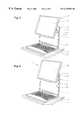
- FIG. 4is a schematic drawing of the computer of FIG. 3 shown with its display at a second stage of deployment.
- FIG. 5is a schematic drawing of the computer of FIG. 3 shown with its display at a third stage of deployment.
- FIG. 6is a schematic drawing of the computer of FIG. 3 shown with its display at a fourth stage of deployment.
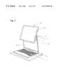
- FIG. 7is a schematic drawing of the computer of FIG. 3 shown with its display at a final stage of deployment.
- an improved notebook computer 21is shown on an airline seat back tray table 23 .
- Tray table 23is pivotally mounted to a seat back 25 and is in its fully extended or open position.
- Seat back 25is in its upright, fully locked position.
- a conventional notebook computer 13is shown on tray table 11 to the left of computer 21 .
- Tray table 11is mounted to seat back 19 which is in a reclined position.
- Computer 21has a base 31 and a cover or lid 33 .
- Base 31comprises a keyboard, a disc drive and various other electrical components for carrying out computing functions.
- the lower edge of lid 33is pivotally mounted to the rearward edge of base 31 so that lid 33 may be positioned at various angular displacements in the range of zero to 180 degrees relative to the user. Lid 33 is limited to about 90 degrees relative to base 31 because of the position of seat back 25 .
- Lid 33has a large recess (not shown) on its front surface which contains and supports a monitor or display 35 which is viewed by the user.
- lid 33 and display 35are both rectangular and display 35 is only slightly smaller than lid 33 .
- Display 35may be viewed in a conventional manner as is done with prior art displays by rotating lid 33 to a preferred angular displacement. In this retracted position, display 35 is substantially flush with lid 33 .
- display 35cannot be placed in an ergonomically correct position for proper viewing by the user because of seat back 25 .
- the images depicted on display 35will appear dark and/or distorted to the user when it is at a poor viewing angle.
- seat back 25is reclined like seat back 19 , the user's view of display 35 will be even worse.
- Device 41preferably comprises a single piece of sheet metal or other material which is bent to form one support link or arm 43 on each side of display 35 (only the right side is shown), but could also comprise two independent arms. Arms 43 pivotally link display 35 to lid 33 . Each arm 43 has two pivot points 45 , 47 (FIG. 4) and is mounted to and extends between adjacent side edges of display 35 and lid 33 . Pivot points 45 , 47 are defined where arm 43 attaches to display 35 and lid 33 , respectively. Pivot points 45 are substantially vertically aligned with the center of gravity of display 35 . Pivot points 47 attach to lid 33 at a position which is elevated above pivot points 45 (when computer 21 is open at about 90 degrees).
- Arms 43 of device 41are designed to latch into lid 33 at two different latching positions which are illustrated by notches or detents 51 , 53 in lid 33 .
- Detents 53are located above detents 51 near the upper edge of lid 33 .
- Each detent 51 , 53contains a spring clip 55 which engages a latching feature on arm 43 , such as a hole or other feature built into each arm 43 .
- Detents 51are provided for retaining display 35 in the standard or conventional position (FIG. 2 ).
- Detents 53are provided for retaining display 35 in a position such that its center of gravity is much closer to the top edge of lid 33 , as will be shown and described more clearly below.
- Spring clips 55are provided for securing display 35 in a selected one of the two positions.
- Device 41also has a release latch (not shown) for disengaging arms 43 from spring clips 55 .
- Display 35may be further articulated for better viewing and to create more clearance between it and seat back 25 .
- lid 33may be rotated forward a selected distance to decrease the angle between it and base 31 to about 80 degrees.
- the viewing angle of display 35is adjusted by tilting or rotating the top edge of display 35 away from the user. Note that orientation of display 35 may be maintained even if the passenger in front of the user chooses to recline seat back 25 toward the user.
- display 35has been elevated by approximately one-half of its height. Although the lower edge of display 35 is shifted forward, the user's view of the keyboard on base 31 is not obscured because of this elevation. If display 35 had not been elevated, the user's view of the keyboard would be obscured and perhaps even inaccessible due to the presence of display 35 .
- the position of display 35 in FIG. 7may tend to block overhead illumination of the keyboard. This is particularly true in a darkened airplane cabin wherein the light is provided only by overhead reading lights.
- computer 21is provided with a small source of light 59 located near the lower edge of display 35 .
- Light 59may comprise a redirected portion of the light emitted from the existing backlight behind display 35 or an entirely separate source.
- the rear surface of the backlightis at least partially exposed or covered with a transparent or semi-transparent cover in order to provide “free” keyboard illumination.
- Portions of arms 43 and/or the inside of lid 33can be made reflective so as to optimize the brightness and uniformity of the keyboard illumination.
- the backlight illumination and, thus, the reflected keyboard illumination from light leaked out of the backlightis not a function of whether the images on display 35 are bright or dark. It is only a function of the overall backlight brightness setting. This guarantees that the keyboard is visible even when a substantially dark image is on the screen.
- the inventionhas several advantages.
- the deviceallows the display to be articulated for better and proper viewing even in limited or cramped conditions. It may also be used to improve ergonomics in other locations such as a desktop.
- the devicedoes not cause the display to disturb the user's view of the keyboard.
- a built-in keyboard lightensures that the keyboard is properly lit even though the display may block some overhead illumination.
- the latching mechanism employedreduces the size, strength and stiffness required of the support arms.
- the location of display ends of the support arms near the center of gravity of the displayreduces the amount of friction necessary to maintain the display in a given orientation.
- the same release latchmay be used to disengage both arms, making it easier for the user to move the display between positions. With the display in the lower position, the computer can be used exactly like a conventional computer.
Landscapes
- Engineering & Computer Science (AREA)
- Computer Hardware Design (AREA)
- Physics & Mathematics (AREA)
- Theoretical Computer Science (AREA)
- Mathematical Physics (AREA)
- Human Computer Interaction (AREA)
- General Engineering & Computer Science (AREA)
- General Physics & Mathematics (AREA)
- Devices For Indicating Variable Information By Combining Individual Elements (AREA)
Abstract
Description
Claims (19)
Priority Applications (1)
| Application Number | Priority Date | Filing Date | Title |
|---|---|---|---|
| US09/282,117US6229693B1 (en) | 1999-03-31 | 1999-03-31 | Articulated display for notebook computer |
Applications Claiming Priority (1)
| Application Number | Priority Date | Filing Date | Title |
|---|---|---|---|
| US09/282,117US6229693B1 (en) | 1999-03-31 | 1999-03-31 | Articulated display for notebook computer |
Publications (1)
| Publication Number | Publication Date |
|---|---|
| US6229693B1true US6229693B1 (en) | 2001-05-08 |
Family
ID=23080171
Family Applications (1)
| Application Number | Title | Priority Date | Filing Date |
|---|---|---|---|
| US09/282,117Expired - Fee RelatedUS6229693B1 (en) | 1999-03-31 | 1999-03-31 | Articulated display for notebook computer |
Country Status (1)
| Country | Link |
|---|---|
| US (1) | US6229693B1 (en) |
Cited By (40)
| Publication number | Priority date | Publication date | Assignee | Title |
|---|---|---|---|---|
| EP0699416A2 (en) | 1994-08-17 | 1996-03-06 | Peter M. Bonutti | Method and apparatus for anchoring a suture |
| US6341061B1 (en) | 1999-12-28 | 2002-01-22 | International Business Machines Corporation | Standup notebook computer |
| JP2002023650A (en)* | 2000-06-14 | 2002-01-23 | Internatl Business Mach Corp <Ibm> | Portable computer device |
| US6381125B1 (en)* | 1999-07-29 | 2002-04-30 | Kabushiki Kaisha Toshiba | Personal computer |
| US6430038B1 (en)* | 2000-04-18 | 2002-08-06 | Hewlett-Packard Company | Computer with articulated mechanism |
| US6437973B1 (en)* | 2000-04-18 | 2002-08-20 | Hewlett-Packard Company | Modular mechanism for movable display |
| US6532147B1 (en)* | 1999-09-24 | 2003-03-11 | International Business Machines Corporation | Flexible monitor/display on mobile device |
| US20030184957A1 (en)* | 2002-04-02 | 2003-10-02 | Stahl Robert Edward | Computer keyboard integrated in aircraft seatback tray table |
| US6665175B1 (en)* | 2002-02-04 | 2003-12-16 | Deboer Carrie | Computer having a monitor that has multiple degrees of freedom with respect to the base of the computer |
| US20040017405A1 (en)* | 2002-07-23 | 2004-01-29 | International Business Machines Corporation | Method and apparatus for implementing a compact portable computer system |
| US20040145862A1 (en)* | 2003-01-28 | 2004-07-29 | International Business Machines Corporation | Laptop display screen and keyboard mounting structure |
| US20040228077A1 (en)* | 2003-04-16 | 2004-11-18 | Hall Rick S. | Height adjustable computer monitor and document holder |
| US20050040681A1 (en)* | 2003-08-19 | 2005-02-24 | Goldman Ira H. | Methods and devices for enhancing health, safety, and comfort on conveyances in relation to reclining seats |
| US20060077309A1 (en)* | 2004-09-27 | 2006-04-13 | Kabushiki Kaisha Toshiba | Broadcast receiving set |
| US20060102719A1 (en)* | 2004-11-15 | 2006-05-18 | Tse-Hua Hsueh | Voting machine with a hinge mechanism |
| KR100671202B1 (en) | 2005-03-11 | 2007-01-19 | 삼성전자주식회사 | Portable computer |
| US7248246B2 (en)* | 2001-05-31 | 2007-07-24 | Intel Corporation | Rack mount server with tiltable display |
| USD551223S1 (en)* | 2006-01-30 | 2007-09-18 | Dell Products L.P. | Portable information handling system |
| US20080174943A1 (en)* | 2003-12-25 | 2008-07-24 | Kiyoshi Hirasawa | Portable Electronic Apparatus |
| US20090231795A1 (en)* | 2008-03-07 | 2009-09-17 | Charles Eric Green | Ergonomic adjustable screen-view technology |
| US20100103603A1 (en)* | 2008-10-29 | 2010-04-29 | Hong Fu Jin Precision Industry (Shenzhen) Co., Ltd | Electronic device |
| US20110043975A1 (en)* | 2009-08-19 | 2011-02-24 | Inventec Corporation | Portable electronic device structure |
| US20110090411A1 (en)* | 2000-06-16 | 2011-04-21 | Finneman Darrell R | Deployable automotive video display |
| US20110126739A1 (en)* | 2009-05-28 | 2011-06-02 | Norman Korpi | Portable, Collapsible, Workstation Tray Table Apparatus |
| US20110211324A1 (en)* | 2009-09-02 | 2011-09-01 | Fujitsu Limited | Mobile terminal device |
| US20110242749A1 (en)* | 2010-04-02 | 2011-10-06 | Compal Electronics, Inc. | Electronic Device |
| US8289685B2 (en)* | 2010-04-23 | 2012-10-16 | Hong Fu Jin Precision Industry (Shenzhen) Co., Ltd. | Portable electronic device |
| USD670295S1 (en)* | 2011-07-15 | 2012-11-06 | Bby Solutions, Inc. | Headrest mount for tablet computer |
| US8390997B1 (en) | 2009-10-06 | 2013-03-05 | Brenda Dominy | Portable computer with adjustable monitor |
| US20130278131A1 (en)* | 2007-05-23 | 2013-10-24 | Sony Corporation | Display device |
| US20140340843A1 (en)* | 2013-05-16 | 2014-11-20 | Acer Incorporated | Electronic device |
| US20150202362A1 (en)* | 2012-07-20 | 2015-07-23 | Fresenius Vial Sas | Syringe pump with pivotable display |
| US20160170448A1 (en)* | 2012-11-22 | 2016-06-16 | Ryota Michino | Portable terminal device, portable terminal and cover for portable terminal |
| US9568957B2 (en)* | 2015-05-05 | 2017-02-14 | Acer Incorporated | Electronic device |
| US20190079563A1 (en)* | 2017-09-11 | 2019-03-14 | Compal Electronics, Inc. | Electronic device |
| CN110908436A (en)* | 2018-09-17 | 2020-03-24 | 仁宝电脑工业股份有限公司 | electronic device |
| US20210103316A1 (en)* | 2019-10-03 | 2021-04-08 | Kate Haffner | Laptop screen elevator system |
| US11297940B2 (en)* | 2016-10-18 | 2022-04-12 | Dataflex International B.V. | Office workplace system |
| US11301005B2 (en)* | 2020-02-12 | 2022-04-12 | Acer Incorporated | Display assembly and portable electronic device |
| TWI821975B (en)* | 2021-04-14 | 2023-11-11 | 仁寶電腦工業股份有限公司 | Electronic device |
Citations (17)
| Publication number | Priority date | Publication date | Assignee | Title |
|---|---|---|---|---|
| US4832419A (en)* | 1987-01-15 | 1989-05-23 | Compaq Computer Corporation | Adjustable display panel for portable computer |
| US4960256A (en)* | 1988-08-08 | 1990-10-02 | Sony Corporation | Holding structure for displaying apparatus |
| DE3935042C1 (en)* | 1989-10-20 | 1991-03-07 | Nixdorf Computer Ag, 4790 Paderborn, De | Flat screen VDU for data processor - has support consisting of stand and linkage for pivotable retention |
| EP0446414A2 (en)* | 1989-10-18 | 1991-09-18 | Sharp Kabushiki Kaisha | Computer device with rotatable display and removable keyboard |
| US5083290A (en)* | 1988-08-31 | 1992-01-21 | Kabushiki Kaisha Toshiba | Lunch box type electronic apparatus |
| US5107402A (en)* | 1989-01-05 | 1992-04-21 | Telemecanique | Portable computer provided with a tilting screen articulated thereon by tilting linkage with a bent shape |
| EP0510814A1 (en)* | 1991-04-23 | 1992-10-28 | Seiko Epson Corporation | Detachable display device for an information processing apparatus |
| US5247285A (en)* | 1992-03-06 | 1993-09-21 | Everex Systems, Inc. | Standup portable personal computer with detachable wireless keyboard and adjustable display |
| US5337212A (en)* | 1992-11-09 | 1994-08-09 | Ncr Corporation | Flip screen for notebook computers |
| US5684513A (en)* | 1995-07-17 | 1997-11-04 | Decker; Mark Randall | Electronic luminescence keyboard system for a portable device |
| US5708561A (en)* | 1996-08-13 | 1998-01-13 | Vivek R. Huilgol | Portable computer having display slidably and rotatably mounted for movement between landscape and portrait orientation and to open and close speaker ports |
| US5777704A (en)* | 1996-10-30 | 1998-07-07 | International Business Machines Corporation | Backlighting an LCD-based notebook computer under varying ambient light conditions |
| US5815225A (en)* | 1997-01-22 | 1998-09-29 | Gateway 2000, Inc. | Lighting apparatus for a portable computer with illumination apertures |
| US5991150A (en)* | 1997-09-09 | 1999-11-23 | International Business Machines Corporation | Self deploying magnifier for a portable computer display screen |
| US6064373A (en)* | 1993-06-29 | 2000-05-16 | Ditzik; Richard J. | Desktop computer with adjustable flat panel screen |
| US6081420A (en)* | 1996-10-01 | 2000-06-27 | Samsung Electronics Co., Ltd. | LCD display apparatus |
| US6094341A (en)* | 1998-07-08 | 2000-07-25 | Lin; Hui | Notebook computer |
- 1999
- 1999-03-31USUS09/282,117patent/US6229693B1/ennot_activeExpired - Fee Related
Patent Citations (19)
| Publication number | Priority date | Publication date | Assignee | Title |
|---|---|---|---|---|
| US4832419A (en)* | 1987-01-15 | 1989-05-23 | Compaq Computer Corporation | Adjustable display panel for portable computer |
| US4960256A (en)* | 1988-08-08 | 1990-10-02 | Sony Corporation | Holding structure for displaying apparatus |
| US5083290A (en)* | 1988-08-31 | 1992-01-21 | Kabushiki Kaisha Toshiba | Lunch box type electronic apparatus |
| US5107402A (en)* | 1989-01-05 | 1992-04-21 | Telemecanique | Portable computer provided with a tilting screen articulated thereon by tilting linkage with a bent shape |
| EP0446414A2 (en)* | 1989-10-18 | 1991-09-18 | Sharp Kabushiki Kaisha | Computer device with rotatable display and removable keyboard |
| US5229757A (en)* | 1989-10-18 | 1993-07-20 | Sharp Kabushiki Kaisha | Computer device having detachable keyboard mounted on a rotatable display |
| DE3935042C1 (en)* | 1989-10-20 | 1991-03-07 | Nixdorf Computer Ag, 4790 Paderborn, De | Flat screen VDU for data processor - has support consisting of stand and linkage for pivotable retention |
| US5347630A (en)* | 1991-04-23 | 1994-09-13 | Seiko Epson Corporation | Computer system having a detachable display |
| EP0510814A1 (en)* | 1991-04-23 | 1992-10-28 | Seiko Epson Corporation | Detachable display device for an information processing apparatus |
| US5247285A (en)* | 1992-03-06 | 1993-09-21 | Everex Systems, Inc. | Standup portable personal computer with detachable wireless keyboard and adjustable display |
| US5337212A (en)* | 1992-11-09 | 1994-08-09 | Ncr Corporation | Flip screen for notebook computers |
| US6064373A (en)* | 1993-06-29 | 2000-05-16 | Ditzik; Richard J. | Desktop computer with adjustable flat panel screen |
| US5684513A (en)* | 1995-07-17 | 1997-11-04 | Decker; Mark Randall | Electronic luminescence keyboard system for a portable device |
| US5708561A (en)* | 1996-08-13 | 1998-01-13 | Vivek R. Huilgol | Portable computer having display slidably and rotatably mounted for movement between landscape and portrait orientation and to open and close speaker ports |
| US6081420A (en)* | 1996-10-01 | 2000-06-27 | Samsung Electronics Co., Ltd. | LCD display apparatus |
| US5777704A (en)* | 1996-10-30 | 1998-07-07 | International Business Machines Corporation | Backlighting an LCD-based notebook computer under varying ambient light conditions |
| US5815225A (en)* | 1997-01-22 | 1998-09-29 | Gateway 2000, Inc. | Lighting apparatus for a portable computer with illumination apertures |
| US5991150A (en)* | 1997-09-09 | 1999-11-23 | International Business Machines Corporation | Self deploying magnifier for a portable computer display screen |
| US6094341A (en)* | 1998-07-08 | 2000-07-25 | Lin; Hui | Notebook computer |
Cited By (54)
| Publication number | Priority date | Publication date | Assignee | Title |
|---|---|---|---|---|
| EP0699416A2 (en) | 1994-08-17 | 1996-03-06 | Peter M. Bonutti | Method and apparatus for anchoring a suture |
| US6381125B1 (en)* | 1999-07-29 | 2002-04-30 | Kabushiki Kaisha Toshiba | Personal computer |
| US6532147B1 (en)* | 1999-09-24 | 2003-03-11 | International Business Machines Corporation | Flexible monitor/display on mobile device |
| US6341061B1 (en) | 1999-12-28 | 2002-01-22 | International Business Machines Corporation | Standup notebook computer |
| US6882529B2 (en) | 2000-04-18 | 2005-04-19 | Hewlett-Packard Development Company, L.P. | Modular mechanism for movable display |
| US6430038B1 (en)* | 2000-04-18 | 2002-08-06 | Hewlett-Packard Company | Computer with articulated mechanism |
| US6437973B1 (en)* | 2000-04-18 | 2002-08-20 | Hewlett-Packard Company | Modular mechanism for movable display |
| US20020145846A1 (en)* | 2000-04-18 | 2002-10-10 | Helot Jacques H. | Modular mechanism for movable display |
| JP2002023650A (en)* | 2000-06-14 | 2002-01-23 | Internatl Business Mach Corp <Ibm> | Portable computer device |
| US6504707B2 (en)* | 2000-06-14 | 2003-01-07 | International Business Machines Corporation | Portable computer |
| US20110090411A1 (en)* | 2000-06-16 | 2011-04-21 | Finneman Darrell R | Deployable automotive video display |
| US7248246B2 (en)* | 2001-05-31 | 2007-07-24 | Intel Corporation | Rack mount server with tiltable display |
| US6665175B1 (en)* | 2002-02-04 | 2003-12-16 | Deboer Carrie | Computer having a monitor that has multiple degrees of freedom with respect to the base of the computer |
| US20030184957A1 (en)* | 2002-04-02 | 2003-10-02 | Stahl Robert Edward | Computer keyboard integrated in aircraft seatback tray table |
| US20040017405A1 (en)* | 2002-07-23 | 2004-01-29 | International Business Machines Corporation | Method and apparatus for implementing a compact portable computer system |
| US6922187B2 (en)* | 2002-07-23 | 2005-07-26 | International Business Machines Corporation | Method and apparatus for implementing a compact portable computer system |
| US6816365B2 (en) | 2003-01-28 | 2004-11-09 | International Business Machines Corporation | Laptop display screen and keyboard mounting structure |
| US20040145862A1 (en)* | 2003-01-28 | 2004-07-29 | International Business Machines Corporation | Laptop display screen and keyboard mounting structure |
| US20040228077A1 (en)* | 2003-04-16 | 2004-11-18 | Hall Rick S. | Height adjustable computer monitor and document holder |
| US7287817B2 (en) | 2003-08-19 | 2007-10-30 | Goldman Ira H | Methods and devices for enhancing health, safety, and comfort on conveyances in relation to reclining seats |
| US20050040681A1 (en)* | 2003-08-19 | 2005-02-24 | Goldman Ira H. | Methods and devices for enhancing health, safety, and comfort on conveyances in relation to reclining seats |
| US20080174943A1 (en)* | 2003-12-25 | 2008-07-24 | Kiyoshi Hirasawa | Portable Electronic Apparatus |
| US20060077309A1 (en)* | 2004-09-27 | 2006-04-13 | Kabushiki Kaisha Toshiba | Broadcast receiving set |
| US20060102719A1 (en)* | 2004-11-15 | 2006-05-18 | Tse-Hua Hsueh | Voting machine with a hinge mechanism |
| KR100671202B1 (en) | 2005-03-11 | 2007-01-19 | 삼성전자주식회사 | Portable computer |
| USD551223S1 (en)* | 2006-01-30 | 2007-09-18 | Dell Products L.P. | Portable information handling system |
| US20130278131A1 (en)* | 2007-05-23 | 2013-10-24 | Sony Corporation | Display device |
| US10067529B2 (en) | 2007-05-23 | 2018-09-04 | Sony Corporation | Display device |
| US9609699B2 (en)* | 2007-05-23 | 2017-03-28 | Sony Corporation | Display device |
| US20090231795A1 (en)* | 2008-03-07 | 2009-09-17 | Charles Eric Green | Ergonomic adjustable screen-view technology |
| US20100103603A1 (en)* | 2008-10-29 | 2010-04-29 | Hong Fu Jin Precision Industry (Shenzhen) Co., Ltd | Electronic device |
| US8050030B2 (en)* | 2008-10-29 | 2011-11-01 | Hong Fu Jin Precision Industry (Shenzhen) Co., Ltd. | Electronic device |
| US8424464B2 (en) | 2009-05-28 | 2013-04-23 | Norman Korpi | Portable, collapsible, workstation tray table apparatus |
| US20110126739A1 (en)* | 2009-05-28 | 2011-06-02 | Norman Korpi | Portable, Collapsible, Workstation Tray Table Apparatus |
| US7903400B1 (en)* | 2009-08-19 | 2011-03-08 | Inventec Corporation | Portable electronic device structure |
| US20110043975A1 (en)* | 2009-08-19 | 2011-02-24 | Inventec Corporation | Portable electronic device structure |
| US8380263B2 (en)* | 2009-09-02 | 2013-02-19 | Fujitsu Limited | Mobile terminal device with sliding display and method thereof |
| US20110211324A1 (en)* | 2009-09-02 | 2011-09-01 | Fujitsu Limited | Mobile terminal device |
| US8390997B1 (en) | 2009-10-06 | 2013-03-05 | Brenda Dominy | Portable computer with adjustable monitor |
| US20110242749A1 (en)* | 2010-04-02 | 2011-10-06 | Compal Electronics, Inc. | Electronic Device |
| US8289685B2 (en)* | 2010-04-23 | 2012-10-16 | Hong Fu Jin Precision Industry (Shenzhen) Co., Ltd. | Portable electronic device |
| USD670295S1 (en)* | 2011-07-15 | 2012-11-06 | Bby Solutions, Inc. | Headrest mount for tablet computer |
| US20150202362A1 (en)* | 2012-07-20 | 2015-07-23 | Fresenius Vial Sas | Syringe pump with pivotable display |
| US20160170448A1 (en)* | 2012-11-22 | 2016-06-16 | Ryota Michino | Portable terminal device, portable terminal and cover for portable terminal |
| US10114409B2 (en)* | 2012-11-22 | 2018-10-30 | Nec Corporation | Portable terminal device, portable terminal and cover for portable terminal |
| US20140340843A1 (en)* | 2013-05-16 | 2014-11-20 | Acer Incorporated | Electronic device |
| US9568957B2 (en)* | 2015-05-05 | 2017-02-14 | Acer Incorporated | Electronic device |
| US11297940B2 (en)* | 2016-10-18 | 2022-04-12 | Dataflex International B.V. | Office workplace system |
| US20190079563A1 (en)* | 2017-09-11 | 2019-03-14 | Compal Electronics, Inc. | Electronic device |
| US10802548B2 (en)* | 2017-09-11 | 2020-10-13 | Compal Electronics, Inc. | Electronic device |
| CN110908436A (en)* | 2018-09-17 | 2020-03-24 | 仁宝电脑工业股份有限公司 | electronic device |
| US20210103316A1 (en)* | 2019-10-03 | 2021-04-08 | Kate Haffner | Laptop screen elevator system |
| US11301005B2 (en)* | 2020-02-12 | 2022-04-12 | Acer Incorporated | Display assembly and portable electronic device |
| TWI821975B (en)* | 2021-04-14 | 2023-11-11 | 仁寶電腦工業股份有限公司 | Electronic device |
Similar Documents
| Publication | Publication Date | Title |
|---|---|---|
| US6229693B1 (en) | Articulated display for notebook computer | |
| US9268141B2 (en) | Desktop electronic magnifier | |
| US6867961B2 (en) | Portable computer | |
| US6876545B2 (en) | Flat panel display apparatus and tilt/swivel mechanism therein | |
| US4930884A (en) | Easy viewing device with shielding | |
| US4528618A (en) | Picture-screen work-station lamp | |
| US6806850B2 (en) | Portable electronic device having projection screen | |
| US5904328A (en) | Articulating computer monitor | |
| JP3974904B2 (en) | Portable computer support device | |
| TW200809465A (en) | Electronic apparatus | |
| US20100294909A1 (en) | Deployable support unit for reading material | |
| US20110180682A1 (en) | Deployable support unit for reading material | |
| US20120293942A1 (en) | Reconfigurable Computer | |
| EP1513047A2 (en) | Electronic device | |
| US20040125549A1 (en) | Laptop computer display mounting | |
| US20080252555A1 (en) | Multimedia notebook having sliding auxiliary dual monitor and desktop lcd monitor having the same | |
| AU5404201A (en) | Digital projection system for phones and personal digital assistants | |
| US5699225A (en) | Combined work platform and personal computer system having a reflective display panel | |
| US5668695A (en) | Portable computer utilizable by an over head projector and tilting mechanism thereof | |
| EP0442893B1 (en) | Draft/copy holder | |
| EP2329336B1 (en) | Computer with integrated light | |
| US5826962A (en) | LCD integrated/overhead projector | |
| US5599083A (en) | Projection apparatus | |
| JP2000184311A (en) | Display device for information processing device | |
| US20070152113A1 (en) | Compressed workspace notebook computer |
Legal Events
| Date | Code | Title | Description |
|---|---|---|---|
| AS | Assignment | Owner name:INTERNATIONAL BUSINESS MACHINES CORPORATION, NEW Y Free format text:ASSIGNMENT OF ASSIGNORS INTEREST;ASSIGNORS:KARIDIS, JOHN P.;HILL, DAVID W.;REEL/FRAME:009870/0324 Effective date:19990330 | |
| FEPP | Fee payment procedure | Free format text:PAYOR NUMBER ASSIGNED (ORIGINAL EVENT CODE: ASPN); ENTITY STATUS OF PATENT OWNER: LARGE ENTITY | |
| FPAY | Fee payment | Year of fee payment:4 | |
| AS | Assignment | Owner name:LENOVO (SINGAPORE) PTE LTD.,SINGAPORE Free format text:ASSIGNMENT OF ASSIGNORS INTEREST;ASSIGNOR:INTERNATIONAL BUSINESS MACHINES CORPORATION;REEL/FRAME:016891/0507 Effective date:20050520 Owner name:LENOVO (SINGAPORE) PTE LTD., SINGAPORE Free format text:ASSIGNMENT OF ASSIGNORS INTEREST;ASSIGNOR:INTERNATIONAL BUSINESS MACHINES CORPORATION;REEL/FRAME:016891/0507 Effective date:20050520 | |
| REMI | Maintenance fee reminder mailed | ||
| LAPS | Lapse for failure to pay maintenance fees | ||
| STCH | Information on status: patent discontinuation | Free format text:PATENT EXPIRED DUE TO NONPAYMENT OF MAINTENANCE FEES UNDER 37 CFR 1.362 | |
| FP | Lapsed due to failure to pay maintenance fee | Effective date:20090508 |