US6229145B1 - Dedicated apparatus and method emission mammography - Google Patents
Dedicated apparatus and method emission mammographyDownload PDFInfo
- Publication number
- US6229145B1 US6229145B1US09/415,979US41597999AUS6229145B1US 6229145 B1US6229145 B1US 6229145B1US 41597999 AUS41597999 AUS 41597999AUS 6229145 B1US6229145 B1US 6229145B1
- Authority
- US
- United States
- Prior art keywords
- body part
- image
- stereotactic
- physiological
- gamma
- Prior art date
- Legal status (The legal status is an assumption and is not a legal conclusion. Google has not performed a legal analysis and makes no representation as to the accuracy of the status listed.)
- Expired - Fee Related
Links
- 238000000034methodMethods0.000titleclaimsdescription45
- 238000009607mammographyMethods0.000titledescription9
- 230000007246mechanismEffects0.000claimsabstractdescription85
- 238000003384imaging methodMethods0.000claimsabstractdescription69
- 230000003100immobilizing effectEffects0.000claimsabstractdescription43
- 239000000700radioactive tracerSubstances0.000claimsabstractdescription34
- 230000005251gamma rayEffects0.000claimsabstractdescription31
- 239000000463materialSubstances0.000claimsabstractdescription10
- 238000004891communicationMethods0.000claimsabstractdescription7
- 206010028980NeoplasmDiseases0.000claimsdescription31
- 238000001574biopsyMethods0.000claimsdescription20
- 230000004807localizationEffects0.000claimsdescription10
- 230000005855radiationEffects0.000claimsdescription5
- 238000012790confirmationMethods0.000claimsdescription3
- 210000000481breastAnatomy0.000description45
- 239000013078crystalSubstances0.000description32
- 230000003902lesionEffects0.000description30
- 238000002600positron emission tomographyMethods0.000description26
- 230000006835compressionEffects0.000description18
- 238000007906compressionMethods0.000description18
- 206010006187Breast cancerDiseases0.000description13
- KRHYYFGTRYWZRS-BJUDXGSMSA-Nac1l2y5hChemical compound[18FH]KRHYYFGTRYWZRS-BJUDXGSMSA-N0.000description12
- 208000026310Breast neoplasmDiseases0.000description11
- 238000001514detection methodMethods0.000description11
- 230000003993interactionEffects0.000description11
- 238000003491arrayMethods0.000description10
- 201000011510cancerDiseases0.000description9
- 230000015654memoryEffects0.000description9
- 230000035945sensitivityEffects0.000description9
- 238000007387excisional biopsyMethods0.000description8
- 238000009206nuclear medicineMethods0.000description7
- 230000005856abnormalityEffects0.000description6
- 150000002303glucose derivativesChemical class0.000description6
- 230000008901benefitEffects0.000description5
- 230000000694effectsEffects0.000description5
- 210000001519tissueAnatomy0.000description5
- 230000003190augmentative effectEffects0.000description4
- 201000008275breast carcinomaDiseases0.000description4
- 238000002059diagnostic imagingMethods0.000description4
- 238000011156evaluationMethods0.000description4
- 230000036210malignancyEffects0.000description4
- 238000004519manufacturing processMethods0.000description4
- 230000001394metastastic effectEffects0.000description4
- 206010061289metastatic neoplasmDiseases0.000description4
- 238000000926separation methodMethods0.000description4
- 238000003325tomographyMethods0.000description4
- 238000002604ultrasonographyMethods0.000description4
- 238000012879PET imagingMethods0.000description3
- 238000004458analytical methodMethods0.000description3
- 230000003247decreasing effectEffects0.000description3
- 238000013461designMethods0.000description3
- 238000005259measurementMethods0.000description3
- 210000000056organAnatomy0.000description3
- 230000004044responseEffects0.000description3
- 238000012216screeningMethods0.000description3
- 238000001356surgical procedureMethods0.000description3
- 206010006272Breast massDiseases0.000description2
- 206010036618Premenstrual syndromeDiseases0.000description2
- 238000013459approachMethods0.000description2
- 230000015572biosynthetic processEffects0.000description2
- 229910052797bismuthInorganic materials0.000description2
- JCXGWMGPZLAOME-UHFFFAOYSA-Nbismuth atomChemical compound[Bi]JCXGWMGPZLAOME-UHFFFAOYSA-N0.000description2
- 238000004364calculation methodMethods0.000description2
- 238000012937correctionMethods0.000description2
- 208000031513cystDiseases0.000description2
- 238000003745diagnosisMethods0.000description2
- 238000009826distributionMethods0.000description2
- 230000004153glucose metabolismEffects0.000description2
- 238000002347injectionMethods0.000description2
- 239000007924injectionSubstances0.000description2
- 238000005304joiningMethods0.000description2
- 230000003211malignant effectEffects0.000description2
- 239000011159matrix materialSubstances0.000description2
- 230000008569processEffects0.000description2
- 230000002285radioactive effectEffects0.000description2
- 239000007787solidSubstances0.000description2
- ZCXUVYAZINUVJD-AHXZWLDOSA-N2-deoxy-2-((18)F)fluoro-alpha-D-glucoseChemical compoundOC[C@H]1O[C@H](O)[C@H]([18F])[C@@H](O)[C@@H]1OZCXUVYAZINUVJD-AHXZWLDOSA-N0.000description1
- 206010002091AnaesthesiaDiseases0.000description1
- 208000009458Carcinoma in SituDiseases0.000description1
- 241000557626Corvus coraxSpecies0.000description1
- 206010011732CystDiseases0.000description1
- 206010058314DysplasiaDiseases0.000description1
- 206010027476MetastasesDiseases0.000description1
- 241001465754MetazoaSpecies0.000description1
- GKLVYJBZJHMRIY-OUBTZVSYSA-NTechnetium-99Chemical compound[99Tc]GKLVYJBZJHMRIY-OUBTZVSYSA-N0.000description1
- 230000002159abnormal effectEffects0.000description1
- 230000006978adaptationEffects0.000description1
- 230000037005anaesthesiaEffects0.000description1
- 230000003466anti-cipated effectEffects0.000description1
- 238000000429assemblyMethods0.000description1
- 230000000712assemblyEffects0.000description1
- 238000000376autoradiographyMethods0.000description1
- 210000004556brainAnatomy0.000description1
- 201000005389breast carcinoma in situDiseases0.000description1
- 230000000747cardiac effectEffects0.000description1
- 230000008094contradictory effectEffects0.000description1
- 230000000120cytopathologic effectEffects0.000description1
- 230000001419dependent effectEffects0.000description1
- 238000000151depositionMethods0.000description1
- 238000011161developmentMethods0.000description1
- 230000004069differentiationEffects0.000description1
- 201000010099diseaseDiseases0.000description1
- 208000037265diseases, disorders, signs and symptomsDiseases0.000description1
- 239000000975dyeSubstances0.000description1
- 238000005516engineering processMethods0.000description1
- 238000001914filtrationMethods0.000description1
- 230000004907fluxEffects0.000description1
- 238000009499grossingMethods0.000description1
- 230000012010growthEffects0.000description1
- 230000006872improvementEffects0.000description1
- 201000004933in situ carcinomaDiseases0.000description1
- 238000001990intravenous administrationMethods0.000description1
- 238000007726management methodMethods0.000description1
- 230000000149penetrating effectEffects0.000description1
- 210000002307prostateAnatomy0.000description1
- 238000013139quantizationMethods0.000description1
- 238000002601radiographyMethods0.000description1
- 230000009467reductionEffects0.000description1
- 230000029058respiratory gaseous exchangeEffects0.000description1
- 238000005070samplingMethods0.000description1
- 230000037390scarringEffects0.000description1
- 239000000243solutionSubstances0.000description1
- 229940056501technetium 99mDrugs0.000description1
- 230000004614tumor growthEffects0.000description1
- XLYOFNOQVPJJNP-UHFFFAOYSA-NwaterSubstancesOXLYOFNOQVPJJNP-UHFFFAOYSA-N0.000description1
Images


Classifications
- A—HUMAN NECESSITIES
- A61—MEDICAL OR VETERINARY SCIENCE; HYGIENE
- A61B—DIAGNOSIS; SURGERY; IDENTIFICATION
- A61B6/00—Apparatus or devices for radiation diagnosis; Apparatus or devices for radiation diagnosis combined with radiation therapy equipment
- A61B6/04—Positioning of patients; Tiltable beds or the like
- A61B6/0407—Supports, e.g. tables or beds, for the body or parts of the body
- A61B6/0414—Supports, e.g. tables or beds, for the body or parts of the body with compression means
- A—HUMAN NECESSITIES
- A61—MEDICAL OR VETERINARY SCIENCE; HYGIENE
- A61B—DIAGNOSIS; SURGERY; IDENTIFICATION
- A61B6/00—Apparatus or devices for radiation diagnosis; Apparatus or devices for radiation diagnosis combined with radiation therapy equipment
- A61B6/42—Arrangements for detecting radiation specially adapted for radiation diagnosis
- A61B6/4208—Arrangements for detecting radiation specially adapted for radiation diagnosis characterised by using a particular type of detector
- A61B6/4258—Arrangements for detecting radiation specially adapted for radiation diagnosis characterised by using a particular type of detector for detecting non x-ray radiation, e.g. gamma radiation
- A—HUMAN NECESSITIES
- A61—MEDICAL OR VETERINARY SCIENCE; HYGIENE
- A61B—DIAGNOSIS; SURGERY; IDENTIFICATION
- A61B6/00—Apparatus or devices for radiation diagnosis; Apparatus or devices for radiation diagnosis combined with radiation therapy equipment
- A61B6/50—Apparatus or devices for radiation diagnosis; Apparatus or devices for radiation diagnosis combined with radiation therapy equipment specially adapted for specific body parts; specially adapted for specific clinical applications
- A61B6/502—Apparatus or devices for radiation diagnosis; Apparatus or devices for radiation diagnosis combined with radiation therapy equipment specially adapted for specific body parts; specially adapted for specific clinical applications for diagnosis of breast, i.e. mammography
- A—HUMAN NECESSITIES
- A61—MEDICAL OR VETERINARY SCIENCE; HYGIENE
- A61B—DIAGNOSIS; SURGERY; IDENTIFICATION
- A61B6/00—Apparatus or devices for radiation diagnosis; Apparatus or devices for radiation diagnosis combined with radiation therapy equipment
- A61B6/54—Control of apparatus or devices for radiation diagnosis
- A61B6/547—Control of apparatus or devices for radiation diagnosis involving tracking of position of the device or parts of the device
- G—PHYSICS
- G01—MEASURING; TESTING
- G01T—MEASUREMENT OF NUCLEAR OR X-RADIATION
- G01T1/00—Measuring X-radiation, gamma radiation, corpuscular radiation, or cosmic radiation
- G01T1/16—Measuring radiation intensity
- G01T1/161—Applications in the field of nuclear medicine, e.g. in vivo counting
- G01T1/164—Scintigraphy
- G01T1/1641—Static instruments for imaging the distribution of radioactivity in one or two dimensions using one or several scintillating elements; Radio-isotope cameras
- G01T1/1642—Static instruments for imaging the distribution of radioactivity in one or two dimensions using one or several scintillating elements; Radio-isotope cameras using a scintillation crystal and position sensing photodetector arrays, e.g. ANGER cameras
Definitions
- the present inventionis related to an apparatus for medical examination. More specifically, the present invention is related to an apparatus and method for imaging the radiotracer concentration in a female breast or other organ.
- Mammographyis currently the most effective method of screening for breast cancer.
- the goal of breast cancer screeningis the detection of early non-palpable tumors.
- mammographyis very sensitive in the detection of cancer, it is not very specific in determining whether mammographic abnormalities are due to benign or malignant disease (Limitations of Mammography in the Identification of Noninfiltrating Carcinoma of the Breast, S. F. Sener, F. C. Candela, M. L. Paige, J. R. Bernstein, D. P. Winchester, Surgery, Gynecology, and Obstetrics, Aug. 1988, 167:135-140). Therefore, a noninvasive method of confirming the malignancy of suspicious mammographic abnormalities would be a major benefit in patient care. In this way, the number of benign excisional biopsies (approximately 75% of all excisional biopsies) can be reduced.
- the role of ultrasound in clarifying the status of a mammographic abnormalityis limited to the differentiation of solid masses from benign cysts. If the strict criteria for the ultrasonic appearance of a simple cyst are satisfied, the referring physician may be reassured that the lesion is benign. Unfortunately, the current spatial resolution of ultrasound makes the technique of limited value for lesions significantly smaller than five millimeters.
- Doppler ultrasoundhas been advocated as a means for differentiating benign from malignant masses, but results of clinical trials have been contradictory, and the doppler method has no current clinical role in breast imaging (The Role of US in Breast Imaging, V. P. Jackson, Radiology, Nov. 1990, 177:305-311).
- Fine-Needle Aspiration (FNA) of breast massesis a technique whose sensitivity and specificity is operator dependent (Fine-Needle Aspiration Biopsies of Breast Masses, L. Palombini et al., Cancer, Jun. 1, 1988, 61:2273-2277), and has been considered experimental (Discriminating Analysis Uncovers Breast Lesions, D. B. Kopans, Diagnostic Imaging, Sept. 1991, pp. 94-101). Because of its relatively low cost and reduced morbidity associated with surgery and anesthesia, FNA has been suggested as a possible replacement for excisional biopsy. Unfortunately, there is a high (13-50%) rate of insufficient samples when FNA is performed on non-palpable mammographically detected lesions.
- FNAFNA as a non-imaging diagnostic modality, has the disadvantage that no information is obtained about the physical distribution of the detected tumor.
- FNAcannot easily differentiate between cases of marked dysplasia, carcinoma-in-situ, or invasive cancer. Fine-Needle Aspiration is generally not performed for non-palpable breast lesions.
- Another option for the referral of a patient with equivocal mammographic anomaliesis excisional biopsy of the breast in the area corresponding to the region of mammographic abnormality.
- the probability of malignancyranges from 2% for a circumscribed solid mass to almost 90% for a spiculated ill-defined mass (Discriminating Analysis Uncovers Breast Lesions, D. B. Kopans, Diagnostic Imaging, Sep. 1991, pp. 94-101.
- the true-positive fraction for biopsies obtained as a result of a mammographic screening programis between twenty and thirty percent (Nonpalpable Breast Lesions: Accuracy of Prebiopsy Mammographic Diagnosis, G. Hermann, C. Janus, I. S. Schwartz, B. Krivisky, S.
- Excisional biopsyhas the additional disadvantage of introducing scarring, which may render interpretation of follow-up mammograms more difficult (Discriminating Analysis Uncovers Breast Lesions, D. B. Kopans, Diagnostic Imaging, Sep. 1991, pp. 94-101).
- An additional disadvantage to excisional biopsiesis that, as a non-imaging modality, the physical distribution of the tumor is poorly described.
- FDG2-[F-18]-Fluoro-2-deoxy-D-glucose
- FDGis a radioactive analogue of glucose that is taken up preferentially by cancer cells
- Primary and Metastatic Breast CarcinomaInitial Clinical Evaluation with PET with the Radiolabeled Glucose Analogue 2-[F-18]-Fluoro-2-deoxy-D-glucose, R. L. Wahl, R. L. Cody, G. D. Hutchins, E. E. Mudgett, Radiology (1991) 179:765-770).
- a Fluorine-18 nucleusdecays by emitting a positron which is annihilated within a millimeter by an electron.
- the result of this annihilationis the production of two 511 kev (thousand electron volts) gamma rays that are approximately 180 degrees apart in direction.
- After a patient has received an intravenous dose of FDG shemay be examined with detectors that sense these gamma rays.
- Previous detection methodshave included imaging with a specially collimated planar gamma camera ([18-F] Fluorodeoxyglucose scintigraphy in diagnosis and follow up of treatment in advanced breast cancer, European Journal of Nuclear Medicine (1989) 15:61-66) and with a whole-body Positron Emission Tomography (PET) scanner (Primary and Metastatic Breast Carcinoma: Initial Clinical Evaluation with PET with the Radiolabeled Glucose Analogue 2-[F-18]-Fluoro-2-deoxy-D-glucose, R. L. Wahl, R. L. Cody, G. D. Hutchins, E. E. Mudgett, Radiology (1991) 179:765-770).
- PET imaging of breast cancer patients given FDGhas been shown to be useful in imaging tumors as small as 3.2 cm and in patients whose breasts are too dense to be imaged well mammographically (Primary and Metastatic Breast Carcinoma: Initial Clinical Evaluation with PET with the Radiolabeled Glucose Analogue 2-[F-18]-Fluoro-2-deoxy-D-glucose, R. L. Wahl, R. L. Cody, G. D. Hutchins, E. E. Mudgett, Radiology (1991) 179:765-770).
- a second disadvantage of a conventional PET scanner for imaging of subtle lesions in the breastis the high cost of the examination.
- a conventional PET scannerIn order to accommodate the entire body, a conventional PET scanner must employ tens or hundreds of expensive detector arrays along with a gantry and associated electronics.
- a third disadvantage of a PET scanneris that the PET image format would not be easily compared to conventional mammograms. This is due to the fact that the breast is an organ which can be compressed to an essentially two-dimensional object. The variability in internal architecture of the breast results in few landmarks for positioning, and the location of an anomaly on the mammographic image of the compressed breast does not always correspond to the same location in the non-compressed breast.
- High resolution (20 cm diameter bore) PET scannersoriginally developed for animal studies, may soon be available commercially.
- the resolution in the axial planeis 3.5 mm (Development of a High Resolution PET, T. Yamashita et al., IEEE Transactions on Nuclear Science, April 1990, Vol. 37 (2) pp. 594-599).
- Such a systemwould satisfy the goal of high resolution.
- a disadvantagewould be the considerable cost of such relatively expensive scanners, with approximately fifteen detector arrays, as dedicated units for breast imaging. Further, the problems of immobilization of the breast and of comparison to standard mammography would still be unaddressed.
- the present inventionis an apparatus for examining a body part.
- the apparatuscomprises means or a mechanism for immobilizing and compressing the body part.
- the apparatusalso comprises means or a mechanism for providing an internal anatomical image of the body part and means or a mechanism for detecting single gamma-rays emitted by a radiotracer infiltrated into the body part.
- the detecting mechanismis disposed in an adjacent relationship with the means or mechanism for providing an internal anatomic image so that the body part remains in the same position during and between anatomic and radiotracer imaging.
- the detecting means or mechanismincludes a detector module disposed on one side of the immobilizing means or mechanism.
- the detector modulepreferably has at least one array of gamma ray sensitive material in communication with a position detector.
- the detecting means or mechanismincludes a pair of detector modules disposed one on each side of the immobilizing means or mechanism.
- the means or mechanism for providing an anatomical imageincludes an x-ray source and x-ray recording medium.
- the present inventionis also an apparatus for examining a body part which comprises means or a mechanism for immobilizing and compressing the body part and means or a mechanism for detecting single gamma-rays emitted by a radiotracer infiltrated into the body part.
- the present inventionis also an apparatus for examining a body part which comprises means or a mechanism for immobilizing and compressing the body part and means or a mechanism for providing a stereotactic internal anatomical image of the body part.
- the apparatusalso comprises means or a mechanism for providing a stereotactic physiological image of the body part in an adjacent relationship with the means or mechanism for providing an internal anatomic image such that the body part remains in the same position during and between stereotactic anatomic and radiotracer imaging.
- the means or mechanism for obtaining a stereotactic physiological imageincludes a pair of detector modules disposed one on each side of the immobilizing means or mechanism.
- the detector modulesare constructed to travel angularly about the body part to provide projection images of the body part from at least two different viewing angles.
- the detector modulesare stationary with respect to the body part and obtain multiple projection views of the body part.
- the present inventionis also an apparatus for examining a body part which comprises means or a mechanism for immobilizing and compressing the body part and means or a mechanism for providing a stereotactic physiological image of the body part.
- the present inventionis also a method for examining a body part.
- the methodcomprises the steps of immobilizing the body part in a preferred position such that the body part is compressed. Then there is the step of obtaining at least one physiological image of the body part.
- the step of injecting the patient with a radiotracer which emits gamma rays and the step of obtaining at least one physiological imageincludes the step of detecting gamma-rays with at least one detector module disposed on at least one side of the body part.
- the step of obtaining at least one physiological imagethere can be the step of directing a biopsy needle or gun into the body part 12 using at least one physiological image for guidance and placement.
- the step of obtaining the image or imagesthere can then be the step of operating on the patient using the image or images for guidance, localization, and preferably confirmation that the tumor has been removed completely.
- the operating stepthere can be the step of obtaining at least one image of surgical specimens to identify the presence of and the borders of tumors.
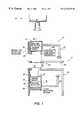
- FIG. 1is a schematic representation of an apparatus for examining a body part.
- FIG. 2is a schematic representation showing a close-up view of the detector modules of the apparatus for examining a body part.
- FIGS. 3 a and 3 bare schematic representations showing the arrangement of the sensor array on the Photomultiplier (PMT).
- FIG. 4is a schematic representation showing a plurality of imaging planes between the detector modules.
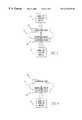
- FIG. 5is a schematic representation of a gamma-ray stereotactic imaging apparatus with two gamma-ray detector modules configured for coincidence detection or for dual-head single-emission acquisition.
- FIG. 6is a schematic representation of a gamma-ray imaging apparatus with a gamma-ray detector module-configured for single-head single-emission acquisition.
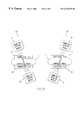
- FIG. 7is a schematic representation of an x-ray stereotactic imaging apparatus.
- FIG. 8is a schematic representation of a gamma-ray stereotactic imaging apparatus with mobile detector arrays.
- FIG. 9is a schematic representation of a gamma-ray stereotactic imaging apparatus with stationary detector arrays.
- FIG. 1there is shown an apparatus 10 for examining a body part 12 , such as a breast.
- the apparatus 10includes means or a mechanism 14 for providing an anatomical image of the body part 12 and means or mechanism 16 for providing a physiological image of the body part 12 .
- the means or mechanism 16 for providing a physiological imageis disposed adjacent to the means or mechanism 14 for providing an anatomical image such that the body part 12 remains in the same position during and between anatomical and physiological imaging.
- the body part 12is infiltrated with a radiotracer and the means or mechanism 16 for providing a physiological image includes means or a mechanism for detecting emissions of the radiotracers from the body part 12 .
- the radiotracerscan be 2-[F-18]-fluoro-2-deoxy-D-glucose (FDG) or 16 alpha-[F-18]-fluoroestradiol-17 beta or other radiotracers.
- the means or mechanism for providing an anatomical imageincludes an x-ray source and x-ray recording medium, such as x-ray film.
- a digital radiography devicecan be used.
- other methods of anatomic imagingsuch as magnetic resonance can be used.
- other methods of anatomic imagingsuch as ultrasound can be used.
- the radiotracerproduces gamma rays and the detecting means or mechanism includes two detector modules 20 each of which has at least one sensor array 19 of gamma ray sensitive material (scintillator), such as bismuth germanate (BGO) crystals, mounted upon a position detector 21 such as a photomultiplier array or position sensitive photomultiplier.
- a position detector 21such as a photomultiplier array or position sensitive photomultiplier.
- individual light sensorssuch as avalanche photodiodes can be mounted upon each gamma ray detector in the array 19 .
- each detector module 20has a continuous sheet of gamma ray detecting material which is mounted upon a position sensitive multiplier or photomultiplier array.
- the continuous sheet of gamma ray sensitive materialcan have slots with septa on its surface which would operate in a manner similar to the block detectors known in the art of PET scanners.
- each detector module 20has dense shielding 23 for reducing undesirable emissions from other parts of the body.
- each detector module 20is attached to a swing arm 22 for allowing them to swing into and out of an operational portion.
- the apparatus 10includes means or a mechanism 26 for immobilizing the body part 12 , such as with compression.
- the immobilizing means or mechanism 26can include a table 28 and a compression arm 30 which compresses the body part 12 against the table 28 .
- the apparatus 10is not limited to having means or a mechanism 14 for obtaining an anatomical image of the body part 12 .
- the apparatus 10includes means or mechanism 26 for immobilizing the body part 12 and means or mechanism 16 for providing a physiological image of the body part 12 .
- the providing means or mechanism 16is in an adjacent relationship to the immobilizing means or mechanism 26 .
- the immobilizing means or mechanism 26compresses the body part 12 and can include a table 28 upon which the body part 12 rests and a compression arm 30 which compresses the body part against the table 28 .
- the apparatuscould include an immobilizing means or mechanism 26 consisting of a C-arm for intra-operative tumor localization.
- the inventionis also a method of examining a body part of a patient.
- the methodincludes the first step of immobilizing the body part in a preferred position. Then, there is the step of obtaining a physiological image of the body part.
- the immobilizing stepthere is the step of injecting the patient with a radiotracer and the obtaining step includes the step of detecting emissions from the immobilized body part.
- the step of obtaining an anatomical image of the body part such as an x-raycan be performed before the immobilizing step.
- a compression examinationsuch as a spot view compression examination.
- the inventionis also related to an alternative method of examining a body part of a patient.
- This methodincludes the first step of obtaining an anatomical image of the body part. Then, there is the step of obtaining a physiological image of the body part such that the body part remains in the same position during and between anatomical and physiological imaging. Preferably, before the obtaining step, there is the step of immobilizing the body part, such as with compression.
- FDG2-[F-18]-Fluoro-2-deoxy-D-glucose
- FDGis a radiotracer which is a radioactive analogue of glucose that is taken up preferentially by breast cancer cells.
- a more detailed explanation of this processis given in Primary and Metastatic Breast Carcinoma: Initial Clinical Evaluation with PET with the Radiolabeled Glucose Analogue 2-[F-18]-Fluoro-2-deoxy-D-glucose, R. L. Wahl, R. L. Cody, G. D. Hutchins, E. E. Mudgett, Radiology (1991) 179:765-770, incorporated by reference.
- the isotope 18-Fdecays by emitting a positron which is annihilated within a few millimeters by an electron.
- the result of this annihilationis the production of two gamma rays that are approximately 180° apart in direction.
- each detector module 20consists of an array of bismuth germanate crystals which detect the gamma rays produced by the FDG. Each array is mounted upon a position sensitive photomultiplier. Electronic collimation using coincidence gating would yield high sensitivity to emitted radiation. The shielding reduces the number of undesirable emissions detected by the detector modules. Once the detector modules 20 are swung into place an image of the emissions is taken in areas of suspicion.
- the rationale for the apparatusis the adaptation of the standard radiological mammographic geometry for the detection of gamma rays produced by positron-emitting and gamma-emitting radiotracers.
- the apparatuswould incorporate (or be easily mounted upon) a conventional or x-ray mammography unit for straightforward comparison with conventional mammograms.
- the increased sensitivity allowed by the mammographic geometryis expected to permit imaging of suspicious areas in the breast within a short period of time (10-15 minutes), allowing the patient to remain in breast compression for the duration of the scan.
- Use of the inventionresults in exact registration between the conventional mammogram and the image of radiotracer uptake.
- Advantages of the invention over existing technologyinclude high resolution, low cost, reduced dose, and decreased morbidity.
- the dose of radioactivity given to the patientwill be similar to or less than the dose presently used for whole body PET imaging of FDG (approximately ten millicuries), which is within the acceptable radiation dose for diagnostic nuclear medicine techniques.
- the morbidity associated with this dosemust be compared to the morbidity associated with unnecessary excisional biopsy.
- the morbiditymay be compared to that associated with unnecessary mastectomy.
- the morbidityshould be compared to the local recurrence of tumor in an under-resected breast.
- Positron emitterssuch as Fluorine-18 (half-life 110 minutes) can be purchased by breast imaging centers from cyclotrons in most major U.S. cities. Note that the use of the proposed dedicated breast imaging device does not preclude the possibility of following the examination with a whole body PET scanner (if available) when clinically indicated, i.e., to search for metastases in a patient with proven cancer. Additionally, by placing a collimator upon one or both of the detector modules, and operating the apparatus in a non-coincident mode, the apparatus could be used in conjunction with more generally available radioisotopes that emit single photons. Additionally, the apparatus could be taken to the operating room for intra-operative tumor localization.
- the present inventionenvisions an apparatus 100 which is capable of 3-dimensional imaging and offers optimal spatial resolution and sensitivity.
- the apparatus 100is comprised of a first detector module 120 for detecting radiotracer emissions from the body part 12 and a second detector module 121 for detecting radiotracer emissions from the body part 12 .
- the first and second detector modules 120 , 121are disposed adjacent to each other with the body part 12 disposed therebetween.
- the apparatus 100also comprises means or a mechanism 102 for backprojecting detected coincident events with respect to the first and second detector modules 120 , 121 onto a plurality of imaging planes 132 between the first and second detecting modules 120 , 121 .
- the imaging planes 132are shown in FIG. 4 .
- the first detector module 120is comprised of a first sensor array 122 of material sensitive to emissions from the radiotracer and the second detector module 121 is comprised of a second sensor array 123 of material sensitive to emissions from the radiotracer.
- the backprojecting means or mechanism 102comprises means or a mechanism for defining a line 130 between a point on the first sensor array 122 and a point on the second sensor array 123 associated with a coincident event and means or a mechanism for determining the intersection of the line 130 with each imaging plane 132 .
- the apparatus 100also comprises means or a mechanism for determining the distance, d, and angle, a, between the first detector module 120 and the second detector module 121 , such as a position and angle encoder 136 .
- each of the first and second detector modules 120 , 121comprises a position detector, such as imaging PMT (photo multiplier) 108 .
- the apparatus 100also comprises means or a mechanism 104 for displaying the imaging planes such as a digital gamma camera display and acquisition system.
- each of the sensor arrays 122 , 123are comprised of a large array of BGO crystals (20 ⁇ 20 to 40 ⁇ 40).
- the present inventionis also a method of examining a body part 12 .
- the methodcomprises the step of detecting a plurality of coincident events associated with the interaction of radiotracer emissions from the body part 12 with a first and second sensor array 122 and 123 . Then, there is the step of backprojecting the detected coincident events onto a plurality of imaging planes 132 between the first and second sensor arrays 122 and 123 .
- the backprojecting stepincludes the step of defining a line 130 between a point of the first sensor array 122 and a second point of the second sensor array 123 associated with the coincident event and determining the intersection of the line 130 with each imaging plane 132 .
- the backprojecting stepthere is the step of displaying the plurality of imaging planes.
- each of the detector modules 120 , 121comprises a Hamamatsu R394I-02 Imaging PMT 108 with an array 122 , 123 of 37 ⁇ 37 BGO crystals above and below a breast 12 .
- the width of each array 122 , 123is 75 mm, as represented by reference character A.
- Each crystalis 2 ⁇ 2 ⁇ 7 mm.
- the top of each crystalis cut at the optimal angle 250 to break the symmetry to maximize the light collected by the PMT 108 .
- the exact length (7 mm above)is a compromise between efficiency and resolution.
- This sensor array designis based on the belief that techniques which would measure the number of interactions are too complicated to be practical (“Resolution and Sensitivity Improvement in Positron Emission Tomography by the First Interaction Determination” Z. H. Cho and S. C. Juh. IEEE 1991 Medical Imaging Conference (Santa Fe) Record pp. 1623-1627). The effect of multiple interactions is reduced, by reducing the probability of their occurrence. This thin sensor array design will have reduced efficiency, but the other detection possibilities gained by allowing all crystals to be in coincidence will more than make up for this. Oblique rays would normally require the measurement of the depth of interaction in each crystal to maintain good spatial resolution (“A PET Detector with Depth-of-Interaction Determination” P. Bartzakos and C. J. Thompson.
- the first and second detectors modules 120 , 121are separable by raising the upper one.
- the distance, d, between themwould be variable in order to accommodate anatomical variations.
- the angle, a, between themwould be variable to accommodate imaging of organs such as the prostate, that might require non-parallel arrangement of the detector modules.
- Each imaging PMT 108would be connected to three analog-to-digital converters (ADCs) to measure the X and Y coordinates and the observed energy of the gamma ray produced by the FDG radiotracer.
- the PMTs 108would be connected to a coincidence circuit and the backprojecting means or mechanism 102 in order to detect the gamma rays produced by positron annihilations in the region between them.
- ADCsanalog-to-digital converters
- the 511 keV gamma pairmay travel in such directions that they will interact with the first and second arrays 122 , 123 .
- the shape of the crystalsis such that most of the light photons created in such events are detected by the PMT 108 , making good energy identification possible (Probably better than 10% full-width at half-maximum [FWHM] energy resolution).
- the Compton scattered rays from the other 55% of the interactionswill be scattered onto a cone whose most probable apex angle is 45° and will deposit 50 keV in the crystal at a depth of 3 mm.
- the 461 keV raywill then escape and interact beyond the crystal.
- the electronics for event detectionshould be sensitive to the 511 keV photons from photo-electric events and 25-150 keV photons corresponding to single Compton interactions of 511 keV photons, and should be able to discriminate against the single Compton interactions on the basis of their lower energy.
- the coordinates of the crystal in the first sensor array 122is X U , Y U and the coordinates of the crystal in the second sensor array 123 is X L , Y L .
- the eventis thus localized on the line 130 :
- the X i and Y i coordinatescould be determined for that imaging plane 132 .
- the first or upper detector module 120is lowered into place.
- the detector module separation, dis measured with a position encoder 136 .
- the position encoder 136is read to calculate an angle scaling factor.
- Position determining look up tablesare then calculated and saved in the data acquisition system's processor's tables which are part of the backprojecting means or mechanism 102 . Acquisition takes place for a preset time, some 30-50 minutes after the IV FDG injection. When a coincidence is detected, the intersection points with possible 13 imaging planes are calculated by looking in the tables. The resulting 13 coordinates are presented to a modified gamma camera interface, which is set up to do a gated study.
- the 13 coordinate pairsare presented in turn, as if they were in separate phases of the cardiac cycle.
- all imaging planes 132are augmented, via a read-modify-write memory cycle.
- the point of intersection of the line and each imaging planeis proportional to the photon attenuation along that line divided by the product of the crystals' relative sensitivities.
- each imaging plane 132contains an image of all data acquired throughout the study. The data has been, in effect “back-projected” onto all 13 imaging planes, by adding the same number to different locations in each imaging plane 132 .
- An analogycan be made with conventional X-ray tomography in which an X-ray tube and film move in an elliptical motion above and below the patient.
- the imageis formed as an “in focus” image of the plane through which a line joining the focal spot and one point on the film passes through the same point in the patient. Attenuation from other points is blurred by the relative motion.
- each imaging plane 132contains data from annihilations which truly occurred near that plane, and all others.
- the data which truly originated in that planeis in focus, that from other planes is blurred.
- the 13 imaging planes 132can now be examined one by one, or all can be displayed at once.
- the lower display thresholdis raised until the background in normal tissue is almost “black”.
- hot spotswill appear in regions of high glucose metabolism, and “cold spots” in regions of low glucose metabolism.
- cold or hot spotsthe section which contains the highest contrast, or best defined boundaries, is the one which localizes the abnormality best.
- Conventional Gamma Camera software for smoothing, contouring, measurement of area, and enhancementcan be used to process and interpret the image.
- a plastic box having the dimensions of the largest compressed breast section likely to be imagedis filled with FDG solution.
- the normal scanning techniqueis used and the table used to augment memory locations is filled with the value Ke ⁇ p (where ⁇ is the linear attenuation coefficient for 511 keV gamma rays in water, 0.098 cm ⁇ 1 and p is the geometrical path length.
- the crystal efficiency tables in memoryare all set to “1”. Data is then acquired for about one hour.
- This calibration techniquecombines inter-crystal sensitivity and attenuation correction into the backprojection operation scaling, making possible real time image formation.
- the only differenceis that rather than adding “1” to each memory location, a number which compensates for attenuation and inter-crystal sensitivity is added. Assuming the memory depth is only 16 bits, this number must be scaled to prevent quantization errors and over flows. It is anticipated that a number of the order of 100 would be used, with a range of 70 to 130. It may also be necessary to introduce a distortion correction as well in case the imaging response of the PMTs is nonlinear.
- the apparatus 100can be coupled to a minimally modified Gamma Camera acquisition and display computer capable of gated studies. All the calibration tables and line of response (LOR) calculations are self contained, but the highly developed Nuclear Medicine image processing software is well suited for use with the apparatus 100 .
- LORline of response
- FIG. 5shows a gamma-ray stereotactic imaging apparatus with two gamma-ray detector modules configured for coincidence detection or for dual-head single-emission acquisition. Radiotracers that decay by positron emission result in the production of a pair of gamma rays. Although such radiotracers are known to be highly accurate in the detection of breast cancer, recent reports in the literature have supported a role for single photon, gamma ray emitters such as Technetium-99m (A. Waxman et al., Journal of Nuclear Medicine, Vol. 34, Issue 5, Page 139P). Advantages to using such emitters include low cost and ease of availability as compared to positron emitters.
- the apparatus 10 as described abovewould be adaptable for application to single photon emitters by using one or both of the detector modules 20 to detect activity from the compressed breast. (See FIGS. 5 and 6.)
- Immobilization/compressionallows confident registration to be performed with x-ray images, thereby increasing diagnostic confidence in the ability of the emission image to characterize a lesion initially detected by x-rays.
- stereotactic guidanceis a technique employed by radiologists to direct biopsies using x-ray images.
- the techniqueconsists of the acquisition of two projection images that differ in projection angle.
- the data afforded by having the two imagesallows the depth of a lesion to be assessed, just as the human brain can assess the depth of an object by integrating information from both eyes.
- the lack of internal stable structures in the breastrequire that the breast be immobilized during acquisition of both projections, without releasing compression between acquisitions.
- biopsy gunsincorporate hollow needle assemblies that allow a core of tissue to be removed. Surgeons often request that hooks, needles, or dyes be placed in a suspicious lesion under mammographic guidance so that the surgeon can later identify the lesion in the operating room. Placement of such localizing hardware can be accomplished using stereotactic guidance.
- One application of the present inventionto use stereotactic guidance to provide projection images that can be used for stereotactic biopsy guidance.
- a stereotactic x-ray mammographic unitFIG. 7
- the x-ray detector moduletravels a certain angle between the stereotactic views (usually 15 degrees) while the patient's breast 12 is under compression.
- the gamma-ray detector modules 20can be positioned so as to travel a specified angle as well.
- the gamma camerasobtain information from many projections, it is possible to have the gamma ray detector modules 20 remain in a single location while multiple projection views were obtained for stereotactic guidance (FIG. 9 ).
- the projections obtained from such projection viewscan be inspected by a human operator to detect a lesion. If the lesion is visible on more than one projection view, calculations similar to those performed for x-ray stereotactic guidance can be performed to determine the depth of the lesion. The coordinates of the lesion can then be used to guide biopsy.
- stereotactic guidancehas never been done using gamma cameras.
- the principal advantage of stereotactic guidance using gamma ray imagingrelates to the requirement for sampling or excising lesions which might be only detectable using gamma-ray imaging techniques. It is a medical dictum that a detection method is not helpful if the results cannot be confirmed by biopsy, and current gamma cameras and positron emission tomography scanners are not well-suited to guide biopsies. This is due to the large size of these imaging devices and their relatively poor detection efficiencies which necessitate long acquisitions times.
- the requirement that a patient remain in compression for acquisition of the stereotactic views and for biopsyimplies that high quality images be obtained in short times.
- the present inventionallows this to happen because the detectors are so close to the breast, and because compression reduces the amount of attenuating tissue between the lesion and the detectors.
- the stereotactic capability of the inventionallows biopsy guidance to be performed on the basis of the emission images alone or in conjunction with the x-ray images, since the gamma-ray detectors are in the same geometry as the conventional x-ray detectors.
- an area of suspicion by x-ray criteriacould be localized by x-ray stereotactic guidance and the presence or extent of the lesion confirmed by gamma-ray imaging prior to biopsy.
- the biopsycould be guided on the basis of the emission images alone.
- the present inventionis an apparatus 10 for examining a body part 12 .
- the apparatuscomprises means or a mechanism 26 for immobilizing and compressing the body part and means or a mechanism 14 for providing an internal anatomical image of the body part.
- the apparatusalso comprises means or a mechanism for detecting single gamma-rays emitted by a radiotracer infiltrated into the body party in an adjacent relationship with said means or mechanism for providing an internal anatomic image such that the body part 12 remains in the same position during and between anatomic and radiotracer imaging.
- the detecting means or mechanismincludes a detector module 20 disposed on one side of the immobilizing means or mechanism 26 .
- the detector module 20preferably has at least one array of gamma ray sensitive material in communication with a position detector.
- the detecting means or mechanismincludes a pair of detector modules 20 disposed one on each side of the immobilizing means or mechanism 26 .
- each detector modulehas at least one array of gamma-ray sensitive material in communication with a position detector.
- the means or mechanism 14 for providing an anatomical imageincludes an x-ray source and x-ray recording medium.
- the present inventionis also an apparatus for examining a body part which comprises means or a mechanism 26 for immobilizing and compressing the body part and means or a mechanism for detecting single gamma-rays emitted by a radiotracer infiltrated into the body part 12 .
- the detecting means or mechanismcan include a detector module disposed on one side of the immobilizing means or mechanism or on both sides. If desired, there can be included means or a mechanism for providing an internal anatomical image of the body part, such as an x-ray device.
- the present inventionis also an apparatus for examining a body part 12 which comprises means or a mechanism 26 for immobilizing and compressing the body part 12 and means or a mechanism 100 for providing a stereotactic internal anatomical image of the body part (FIG. 7 ).
- the apparatusalso comprises means or a mechanism 102 for providing a stereotactic physiological image of the body part in an adjacent relationship with the means or mechanism 100 for providing an internal anatomic image such that the body part remains in the same position during and between anatomic and radiotracer imaging.
- the means or mechanism 102 for obtaining a stereotactic physiological imageincludes a pair of detector modules 20 disposed one on each side of the immobilizing means or mechanism 26 .
- the detector modules 20are constructed to travel angularly about the body part 12 to provide projection images of the body part 12 from at least two different viewing angles, as is well known with x-ray stereotactic imaging.
- the detector modules 20are stationary with respect to the body part 12 and obtain multiple projection views of the body part 12 .
- the present inventionis also an apparatus for examining a body part 12 which comprises means or a mechanism 26 for immobilizing and compressing the body part and means or a mechanism 102 for providing a stereotactic physiological image of the body part.
- detector modules 20can be positioned to travel angularly about the body part 12 to provide projection images of the body part from at least two different viewing angles or detector modules can be stationary with respect to the body part 12 and multiple projection views of the body part are obtained to form a stereotactic image.
- the present inventionis also a method for examining a body part 12 .
- the methodcomprises the steps of immobilizing the body part 12 in a preferred position such that the body part 12 is compressed and obtaining a stereotactic physiological image of the body part.
- the step of injecting the patient with a radiotracer which emits gamma rays and the step of obtaining a stereotactic physiological imageincludes the step of detecting gamma-rays with a pair of detector modules 20 disposed one on each side of immobilizing means or mechanism.
- the step of obtaining a stereotactic physiological imagethere is the step of obtaining a stereotactic internal anatomical image of the body part 12 .
- an imagefor example, a single image or stereotactic images
- the present inventionis also a method for examining a body part 12 .
- the methodcomprises the steps of immobilizing the body part 12 in a preferred position such that the body part 12 is compressed and obtaining at least one physiological image of the body part.
- the step of injecting the patient with a radiotracer which emits gamma rays and the step of obtaining at least one physiological imageincludes the step of detecting gamma-rays with at least one detector module 20 on at least one side of the immobilizing means or mechanism.
- the step of obtaining at least one physiological imagethere can be the step of directing a biopsy needle or gun into the body part 12 using at least one physiological image for guidance and placement.
- the step of obtaining the image or imagesthere can then be the step of operating on the patient using the image or images for guidance, localization, and preferably confirmation that the tumor has been removed completely.
- the operating stepthere can be the step of obtaining at least one image of surgical specimens to identify the presence of and the borders of tumors.
Landscapes
- Health & Medical Sciences (AREA)
- Life Sciences & Earth Sciences (AREA)
- Engineering & Computer Science (AREA)
- Medical Informatics (AREA)
- Physics & Mathematics (AREA)
- Biomedical Technology (AREA)
- General Health & Medical Sciences (AREA)
- Molecular Biology (AREA)
- High Energy & Nuclear Physics (AREA)
- Nuclear Medicine, Radiotherapy & Molecular Imaging (AREA)
- Optics & Photonics (AREA)
- Biophysics (AREA)
- Public Health (AREA)
- Pathology (AREA)
- Heart & Thoracic Surgery (AREA)
- Veterinary Medicine (AREA)
- Surgery (AREA)
- Animal Behavior & Ethology (AREA)
- Radiology & Medical Imaging (AREA)
- Dentistry (AREA)
- Oral & Maxillofacial Surgery (AREA)
- General Physics & Mathematics (AREA)
- Spectroscopy & Molecular Physics (AREA)
- Nuclear Medicine (AREA)
- Apparatus For Radiation Diagnosis (AREA)
Abstract
Description
Claims (28)
Priority Applications (4)
| Application Number | Priority Date | Filing Date | Title |
|---|---|---|---|
| US09/415,979US6229145B1 (en) | 1992-01-22 | 1999-10-12 | Dedicated apparatus and method emission mammography |
| US09/733,680US6545280B2 (en) | 1992-01-22 | 2000-12-08 | Dedicated apparatus and method for emission mammography |
| US10/278,096US6740882B2 (en) | 1992-01-22 | 2002-10-23 | Dedicated apparatus and method for emission mammography |
| US10/780,584US7102134B2 (en) | 1992-01-22 | 2004-02-19 | Dedicated apparatus and method for Positron Emission Tomography of the prostate |
Applications Claiming Priority (5)
| Application Number | Priority Date | Filing Date | Title |
|---|---|---|---|
| US07/824,804US5252830A (en) | 1992-01-22 | 1992-01-22 | Dedicated apparatus and method for emission mammography |
| US08/262,737US5519221A (en) | 1992-01-22 | 1994-06-20 | Dedicated apparatus and method for emission mammography |
| US64755596A | 1996-05-14 | 1996-05-14 | |
| US08/811,915US5965891A (en) | 1992-01-22 | 1997-03-05 | Dedicated apparatus and method for emission mammography |
| US09/415,979US6229145B1 (en) | 1992-01-22 | 1999-10-12 | Dedicated apparatus and method emission mammography |
Related Parent Applications (2)
| Application Number | Title | Priority Date | Filing Date |
|---|---|---|---|
| US08/063,450Continuation-In-PartUS5323006A (en) | 1992-01-22 | 1993-05-18 | Dedicated apparatus and method for emission mammography |
| US08/811,915ContinuationUS5965891A (en) | 1992-01-22 | 1997-03-05 | Dedicated apparatus and method for emission mammography |
Related Child Applications (1)
| Application Number | Title | Priority Date | Filing Date |
|---|---|---|---|
| US09/733,680ContinuationUS6545280B2 (en) | 1992-01-22 | 2000-12-08 | Dedicated apparatus and method for emission mammography |
Publications (1)
| Publication Number | Publication Date |
|---|---|
| US6229145B1true US6229145B1 (en) | 2001-05-08 |
Family
ID=27500750
Family Applications (4)
| Application Number | Title | Priority Date | Filing Date |
|---|---|---|---|
| US09/415,979Expired - Fee RelatedUS6229145B1 (en) | 1992-01-22 | 1999-10-12 | Dedicated apparatus and method emission mammography |
| US09/733,680Expired - Fee RelatedUS6545280B2 (en) | 1992-01-22 | 2000-12-08 | Dedicated apparatus and method for emission mammography |
| US10/278,096Expired - Fee RelatedUS6740882B2 (en) | 1992-01-22 | 2002-10-23 | Dedicated apparatus and method for emission mammography |
| US10/780,584Expired - Fee RelatedUS7102134B2 (en) | 1992-01-22 | 2004-02-19 | Dedicated apparatus and method for Positron Emission Tomography of the prostate |
Family Applications After (3)
| Application Number | Title | Priority Date | Filing Date |
|---|---|---|---|
| US09/733,680Expired - Fee RelatedUS6545280B2 (en) | 1992-01-22 | 2000-12-08 | Dedicated apparatus and method for emission mammography |
| US10/278,096Expired - Fee RelatedUS6740882B2 (en) | 1992-01-22 | 2002-10-23 | Dedicated apparatus and method for emission mammography |
| US10/780,584Expired - Fee RelatedUS7102134B2 (en) | 1992-01-22 | 2004-02-19 | Dedicated apparatus and method for Positron Emission Tomography of the prostate |
Country Status (1)
| Country | Link |
|---|---|
| US (4) | US6229145B1 (en) |
Cited By (42)
| Publication number | Priority date | Publication date | Assignee | Title |
|---|---|---|---|---|
| US6545280B2 (en)* | 1992-01-22 | 2003-04-08 | Pem Technologies, Inc. | Dedicated apparatus and method for emission mammography |
| US6560310B2 (en) | 2000-11-16 | 2003-05-06 | Is2 Research Inc. | Apparatus for mammography |
| US6583420B1 (en)* | 2000-06-07 | 2003-06-24 | Robert S. Nelson | Device and system for improved imaging in nuclear medicine and mammography |
| US20030128033A1 (en)* | 2001-11-15 | 2003-07-10 | Ralph Sinkus | Mammography accessory for MR elastography |
| US6628984B2 (en) | 2000-04-12 | 2003-09-30 | Pem Technologies, Inc. | Hand held camera with tomographic capability |
| US20030194050A1 (en)* | 2002-04-15 | 2003-10-16 | General Electric Company | Multi modality X-ray and nuclear medicine mammography imaging system and method |
| US20050242288A1 (en)* | 2004-04-30 | 2005-11-03 | Wollenweber Scott D | Method and system for normalization of a positron emission tomography system |
| US20080001090A1 (en)* | 2006-06-28 | 2008-01-03 | Spectrum Dynamics Llc | Imaging Techniques For Reducing Blind Spots |
| US20080077005A1 (en)* | 2004-08-12 | 2008-03-27 | Piron Cameron A | System and Method for Multimodality Breast Imaging |
| US20080195249A1 (en)* | 2004-11-09 | 2008-08-14 | Spectrum Dynamics Llc | Radiopharmaceutical dispensing, administration, and imaging |
| US20080306377A1 (en)* | 2003-09-30 | 2008-12-11 | Cameron Anthony Piron | Open architecture imaging apparatus and coil system for magnetic resonance imaging |
| US20100016865A1 (en)* | 2008-07-16 | 2010-01-21 | Dilon Technologies, Inc. | Gamma guided stereotactic localization system |
| US20100174180A1 (en)* | 2004-11-09 | 2010-07-08 | Benny Rousso | Imaging System Customization Using Data From Radiopharmaceutical-Associated Data Carrier |
| US20110034796A1 (en)* | 2009-08-06 | 2011-02-10 | Kayan Ma | Apparatus and method for substantially immobilizing a breast for medical imaging procedure |
| US20110152714A1 (en)* | 2009-06-23 | 2011-06-23 | Luginbuhl Christopher | Variable angle guide holder for a biopsy guide plug |
| US8423125B2 (en) | 2004-11-09 | 2013-04-16 | Spectrum Dynamics Llc | Radioimaging |
| US8445851B2 (en) | 2004-11-09 | 2013-05-21 | Spectrum Dynamics Llc | Radioimaging |
| US8489176B1 (en) | 2000-08-21 | 2013-07-16 | Spectrum Dynamics Llc | Radioactive emission detector equipped with a position tracking system and utilization thereof with medical systems and in medical procedures |
| US8492725B2 (en) | 2009-07-29 | 2013-07-23 | Biosensors International Group Ltd. | Method and system of optimized volumetric imaging |
| US8521253B2 (en) | 2007-10-29 | 2013-08-27 | Spectrum Dynamics Llc | Prostate imaging |
| EP2356660A4 (en)* | 2008-12-09 | 2013-10-09 | Mayo Foundation | COLLIMATOR FOR LOW DOSE MOLECULAR MAMMARY IMAGING |
| US8560051B2 (en) | 2003-09-30 | 2013-10-15 | Hologic, Inc. | Open architecture imaging apparatus and coil system for magnetic resonance imaging |
| US8565860B2 (en) | 2000-08-21 | 2013-10-22 | Biosensors International Group, Ltd. | Radioactive emission detector equipped with a position tracking system |
| US8606349B2 (en) | 2004-11-09 | 2013-12-10 | Biosensors International Group, Ltd. | Radioimaging using low dose isotope |
| US8610075B2 (en) | 2006-11-13 | 2013-12-17 | Biosensors International Group Ltd. | Radioimaging applications of and novel formulations of teboroxime |
| US8620046B2 (en) | 2000-08-21 | 2013-12-31 | Biosensors International Group, Ltd. | Radioactive-emission-measurement optimization to specific body structures |
| US8644910B2 (en) | 2005-07-19 | 2014-02-04 | Biosensors International Group, Ltd. | Imaging protocols |
| US8676292B2 (en) | 2004-01-13 | 2014-03-18 | Biosensors International Group, Ltd. | Multi-dimensional image reconstruction |
| US8744550B2 (en) | 2007-11-23 | 2014-06-03 | Hologic, Inc. | Open architecture tabletop patient support and coil system |
| US8837793B2 (en) | 2005-07-19 | 2014-09-16 | Biosensors International Group, Ltd. | Reconstruction stabilizer and active vision |
| US8894974B2 (en) | 2006-05-11 | 2014-11-25 | Spectrum Dynamics Llc | Radiopharmaceuticals for diagnosis and therapy |
| US8909325B2 (en) | 2000-08-21 | 2014-12-09 | Biosensors International Group, Ltd. | Radioactive emission detector equipped with a position tracking system and utilization thereof with medical systems and in medical procedures |
| EP2582304A4 (en)* | 2010-06-15 | 2015-04-29 | Image Mining Inc | Fiducial systems for mammography |
| US9040016B2 (en) | 2004-01-13 | 2015-05-26 | Biosensors International Group, Ltd. | Diagnostic kit and methods for radioimaging myocardial perfusion |
| US9275451B2 (en) | 2006-12-20 | 2016-03-01 | Biosensors International Group, Ltd. | Method, a system, and an apparatus for using and processing multidimensional data |
| US9316743B2 (en) | 2004-11-09 | 2016-04-19 | Biosensors International Group, Ltd. | System and method for radioactive emission measurement |
| US9332926B2 (en) | 2010-11-25 | 2016-05-10 | Invivo Corporation | MRI imaging probe |
| US9470801B2 (en) | 2004-01-13 | 2016-10-18 | Spectrum Dynamics Llc | Gating with anatomically varying durations |
| US9606245B1 (en) | 2015-03-24 | 2017-03-28 | The Research Foundation For The State University Of New York | Autonomous gamma, X-ray, and particle detector |
| US9646376B2 (en) | 2013-03-15 | 2017-05-09 | Hologic, Inc. | System and method for reviewing and analyzing cytological specimens |
| US9943274B2 (en) | 2004-11-09 | 2018-04-17 | Spectrum Dynamics Medical Limited | Radioimaging using low dose isotope |
| US10964075B2 (en) | 2004-01-13 | 2021-03-30 | Spectrum Dynamics Llc | Gating with anatomically varying durations |
Families Citing this family (38)
| Publication number | Priority date | Publication date | Assignee | Title |
|---|---|---|---|---|
| US6236050B1 (en)* | 1996-02-02 | 2001-05-22 | TüMER TüMAY O. | Method and apparatus for radiation detection |
| JP4358388B2 (en)* | 1999-11-12 | 2009-11-04 | 浜松ホトニクス株式会社 | Positron imaging device |
| FR2810444B1 (en)* | 2000-06-16 | 2006-11-24 | Ge Med Sys Global Tech Co Llc | COLLIMATION DEVICE, RADIOLOGY APPARATUS, TEST KIT, AND TESTING METHOD OF RADIOLOGY APPARATUS |
| WO2002079801A2 (en)* | 2001-03-30 | 2002-10-10 | Duke University | Application specific emission and transmission tomography |
| DE60334771D1 (en)* | 2002-01-08 | 2010-12-16 | Naviscan Inc | EMISSION STORAGE SCANNER WITH OPEN ACCESS |
| US6946658B2 (en)* | 2002-07-05 | 2005-09-20 | The Washington University | Method and apparatus for increasing spatial resolution of a pet scanner |
| US20050089205A1 (en)* | 2003-10-23 | 2005-04-28 | Ajay Kapur | Systems and methods for viewing an abnormality in different kinds of images |
| DE10353611B4 (en)* | 2003-11-17 | 2013-01-17 | Siemens Aktiengesellschaft | X-ray diagnostic device for mammography examinations |
| CN101243332A (en)* | 2005-06-21 | 2008-08-13 | 纳维斯堪Pet系统有限公司 | Tissue interventions using nuclear-emission image guidance |
| US7298816B2 (en)* | 2005-08-02 | 2007-11-20 | The General Hospital Corporation | Tomography system |
| EP1937149A1 (en)* | 2005-10-19 | 2008-07-02 | The General Hospital Corporation | Imaging system and related techniques |
| US8785869B2 (en)* | 2005-11-01 | 2014-07-22 | General Electric Company | System and method for providing emission mammography |
| US20080086059A1 (en)* | 2006-10-04 | 2008-04-10 | Cynthia Keppel | Method and apparatus for lesion localization using a dual modality x-ray/gamma biopsy system |
| EP2091434B1 (en) | 2006-12-11 | 2019-07-17 | Mayo Foundation For Medical Education And Research | System and method for quantitative molecular breast imaging |
| US20100104505A1 (en)* | 2006-12-11 | 2010-04-29 | O'connor Michael K | System and Method for Quantitative Molecular Breast Imaging |
| JP4784649B2 (en)* | 2006-12-15 | 2011-10-05 | 株式会社島津製作所 | Positron CT system |
| US20080221478A1 (en)* | 2007-03-07 | 2008-09-11 | Ritchie Paul G | Integrated Imaging and Biopsy System with Integrated Control Interface |
| IT1391277B1 (en)* | 2008-08-11 | 2011-12-01 | Ist Superiore Sanita | DEVICE FOR THE REVELATION OF SMALL TUMORS IN THE DIAGNOSIS OF BREAST CANCER BY MOLECULAR IMAGING WITH RADIONUCLIDS |
| WO2010048309A2 (en)* | 2008-10-22 | 2010-04-29 | Naviscan, Inc. | A near real-time viewer for pet-guided tissue interventions |
| US8792614B2 (en) | 2009-03-31 | 2014-07-29 | Matthew R. Witten | System and method for radiation therapy treatment planning using a memetic optimization algorithm |
| US8541748B2 (en)* | 2009-06-29 | 2013-09-24 | General Electric Company | System and method for performing nuclear mammography imaging |
| EP2575620B1 (en)* | 2010-06-02 | 2022-01-19 | Mayo Foundation For Medical Education And Research | Method and apparatus for dual-modality ultrasonic and nuclear emission mammography |
| US10159456B2 (en) | 2011-11-22 | 2018-12-25 | Ge Medical Systems Israel, Ltd | Systems and methods for biopsy guidance using a biopsy unit including at least one of an imaging detector or ultrasound probe concurrently mounted with a biopsy guide |
| US9974500B2 (en) | 2014-07-11 | 2018-05-22 | Ge Medical Systems Israel, Ltd. | Systems and methods for open imaging |
| US9709686B2 (en)* | 2014-12-30 | 2017-07-18 | General Electric Company | Modular positron emission tomography (PET) gantry |
| GB2536650A (en) | 2015-03-24 | 2016-09-28 | Augmedics Ltd | Method and system for combining video-based and optic-based augmented reality in a near eye display |
| US11980507B2 (en) | 2018-05-02 | 2024-05-14 | Augmedics Ltd. | Registration of a fiducial marker for an augmented reality system |
| US11766296B2 (en) | 2018-11-26 | 2023-09-26 | Augmedics Ltd. | Tracking system for image-guided surgery |
| US12178666B2 (en) | 2019-07-29 | 2024-12-31 | Augmedics Ltd. | Fiducial marker |
| US11980506B2 (en) | 2019-07-29 | 2024-05-14 | Augmedics Ltd. | Fiducial marker |
| US11382712B2 (en) | 2019-12-22 | 2022-07-12 | Augmedics Ltd. | Mirroring in image guided surgery |
| US11389252B2 (en) | 2020-06-15 | 2022-07-19 | Augmedics Ltd. | Rotating marker for image guided surgery |
| US12239385B2 (en) | 2020-09-09 | 2025-03-04 | Augmedics Ltd. | Universal tool adapter |
| US11896445B2 (en) | 2021-07-07 | 2024-02-13 | Augmedics Ltd. | Iliac pin and adapter |
| US12150821B2 (en) | 2021-07-29 | 2024-11-26 | Augmedics Ltd. | Rotating marker and adapter for image-guided surgery |
| WO2023021448A1 (en) | 2021-08-18 | 2023-02-23 | Augmedics Ltd. | Augmented-reality surgical system using depth sensing |
| EP4511809A1 (en) | 2022-04-21 | 2025-02-26 | Augmedics Ltd. | Systems and methods for medical image visualization |
| IL319523A (en) | 2022-09-13 | 2025-05-01 | Augmedics Ltd | Augmented reality eyewear for image-guided medical intervention |
Citations (11)
| Publication number | Priority date | Publication date | Assignee | Title |
|---|---|---|---|---|
| US4135089A (en) | 1975-02-07 | 1979-01-16 | Mcintyre John A | Method of and apparatus for producing images for stereoscopic viewing of annihilation radiation sources |
| JPS5510589A (en) | 1978-05-01 | 1980-01-25 | Anglo Amer Corp South Africa | Method and device for testing battery condition |
| JPS59180477A (en) | 1983-03-31 | 1984-10-13 | Shimadzu Corp | Emission ct apparatus |
| US5051257A (en) | 1989-05-09 | 1991-09-24 | Pietronigro Dennis D | Antineoplastic solution and method for treating neoplasms |
| US5077034A (en) | 1990-03-30 | 1991-12-31 | The President And Fellows Of Harvard College | Treatment of tumors with 5-radioiodo-2'-deoxyuridine |
| US5219351A (en)* | 1990-10-24 | 1993-06-15 | General Electric Cgr S.A. | Mammograph provided with an improved needle carrier |
| WO1993017620A1 (en) | 1992-03-12 | 1993-09-16 | Fischer Imaging Corporation | Isocentric puncture instrument aiming device |
| US5252830A (en) | 1992-01-22 | 1993-10-12 | Irving Weinberg | Dedicated apparatus and method for emission mammography |
| US5308352A (en)* | 1989-11-17 | 1994-05-03 | Koutrouvelis Panos G | Stereotactic device |
| US5323006A (en) | 1992-01-22 | 1994-06-21 | Frederick M. Mako | Dedicated apparatus and method for emission mammography |
| US5519221A (en)* | 1992-01-22 | 1996-05-21 | Ansel M. Schwartz | Dedicated apparatus and method for emission mammography |
Family Cites Families (6)
| Publication number | Priority date | Publication date | Assignee | Title |
|---|---|---|---|---|
| JPS5817620A (en) | 1981-07-24 | 1983-02-01 | Toshiba Corp | Semiconductor wafer processing method |
| US4981142A (en)* | 1988-06-24 | 1991-01-01 | Dachman Abraham H | Compression device |
| US5046498A (en)* | 1991-01-16 | 1991-09-10 | Union Carbide Industrial Gases Technology Corporation | Magnetic resonance human medical and veterinary imaging method |
| US5931774A (en)* | 1991-06-14 | 1999-08-03 | Proxima Therapeutics, Inc. | Inflatable devices for tumor treatment |
| JP3047559B2 (en) | 1991-07-12 | 2000-05-29 | 堺化学工業株式会社 | Organophosphorus compound composition |
| US6229145B1 (en)* | 1992-01-22 | 2001-05-08 | Pem Technologies, Inc. | Dedicated apparatus and method emission mammography |
- 1999
- 1999-10-12USUS09/415,979patent/US6229145B1/ennot_activeExpired - Fee Related
- 2000
- 2000-12-08USUS09/733,680patent/US6545280B2/ennot_activeExpired - Fee Related
- 2002
- 2002-10-23USUS10/278,096patent/US6740882B2/ennot_activeExpired - Fee Related
- 2004
- 2004-02-19USUS10/780,584patent/US7102134B2/ennot_activeExpired - Fee Related
Patent Citations (11)
| Publication number | Priority date | Publication date | Assignee | Title |
|---|---|---|---|---|
| US4135089A (en) | 1975-02-07 | 1979-01-16 | Mcintyre John A | Method of and apparatus for producing images for stereoscopic viewing of annihilation radiation sources |
| JPS5510589A (en) | 1978-05-01 | 1980-01-25 | Anglo Amer Corp South Africa | Method and device for testing battery condition |
| JPS59180477A (en) | 1983-03-31 | 1984-10-13 | Shimadzu Corp | Emission ct apparatus |
| US5051257A (en) | 1989-05-09 | 1991-09-24 | Pietronigro Dennis D | Antineoplastic solution and method for treating neoplasms |
| US5308352A (en)* | 1989-11-17 | 1994-05-03 | Koutrouvelis Panos G | Stereotactic device |
| US5077034A (en) | 1990-03-30 | 1991-12-31 | The President And Fellows Of Harvard College | Treatment of tumors with 5-radioiodo-2'-deoxyuridine |
| US5219351A (en)* | 1990-10-24 | 1993-06-15 | General Electric Cgr S.A. | Mammograph provided with an improved needle carrier |
| US5252830A (en) | 1992-01-22 | 1993-10-12 | Irving Weinberg | Dedicated apparatus and method for emission mammography |
| US5323006A (en) | 1992-01-22 | 1994-06-21 | Frederick M. Mako | Dedicated apparatus and method for emission mammography |
| US5519221A (en)* | 1992-01-22 | 1996-05-21 | Ansel M. Schwartz | Dedicated apparatus and method for emission mammography |
| WO1993017620A1 (en) | 1992-03-12 | 1993-09-16 | Fischer Imaging Corporation | Isocentric puncture instrument aiming device |
Cited By (65)
| Publication number | Priority date | Publication date | Assignee | Title |
|---|---|---|---|---|
| US6740882B2 (en) | 1992-01-22 | 2004-05-25 | Naviscan Pet Systems, Inc. | Dedicated apparatus and method for emission mammography |
| US6545280B2 (en)* | 1992-01-22 | 2003-04-08 | Pem Technologies, Inc. | Dedicated apparatus and method for emission mammography |
| US7102134B2 (en) | 1992-01-22 | 2006-09-05 | Naviscan Pet Systems, Inc. | Dedicated apparatus and method for Positron Emission Tomography of the prostate |
| US20040183022A1 (en)* | 1992-01-22 | 2004-09-23 | Irving Weinberg | Dedicated apparatus and method for emission mammography |
| US6628984B2 (en) | 2000-04-12 | 2003-09-30 | Pem Technologies, Inc. | Hand held camera with tomographic capability |
| US6583420B1 (en)* | 2000-06-07 | 2003-06-24 | Robert S. Nelson | Device and system for improved imaging in nuclear medicine and mammography |
| US20030205676A1 (en)* | 2000-06-07 | 2003-11-06 | Nelson Robert Sigurd | Device and system for improved imaging in nuclear medicine and mamMography |
| US8489176B1 (en) | 2000-08-21 | 2013-07-16 | Spectrum Dynamics Llc | Radioactive emission detector equipped with a position tracking system and utilization thereof with medical systems and in medical procedures |
| US8565860B2 (en) | 2000-08-21 | 2013-10-22 | Biosensors International Group, Ltd. | Radioactive emission detector equipped with a position tracking system |
| US8620046B2 (en) | 2000-08-21 | 2013-12-31 | Biosensors International Group, Ltd. | Radioactive-emission-measurement optimization to specific body structures |
| US8909325B2 (en) | 2000-08-21 | 2014-12-09 | Biosensors International Group, Ltd. | Radioactive emission detector equipped with a position tracking system and utilization thereof with medical systems and in medical procedures |
| US9370333B2 (en) | 2000-08-21 | 2016-06-21 | Biosensors International Group, Ltd. | Radioactive-emission-measurement optimization to specific body structures |
| US6560310B2 (en) | 2000-11-16 | 2003-05-06 | Is2 Research Inc. | Apparatus for mammography |
| US6833703B2 (en)* | 2001-11-15 | 2004-12-21 | Koninklijke Philips Electronics N.V. | Mechanical oscillator for MR elastography |
| US20030128033A1 (en)* | 2001-11-15 | 2003-07-10 | Ralph Sinkus | Mammography accessory for MR elastography |
| US20030194050A1 (en)* | 2002-04-15 | 2003-10-16 | General Electric Company | Multi modality X-ray and nuclear medicine mammography imaging system and method |
| US9241765B2 (en) | 2003-09-30 | 2016-01-26 | Invivo Corporation | Open architecture imaging apparatus and coil system for magnetic resonance imaging |
| US8571632B2 (en) | 2003-09-30 | 2013-10-29 | Hologic, Inc. | Open architecture imaging apparatus and coil system for magnetic resonance imaging |
| US20080306377A1 (en)* | 2003-09-30 | 2008-12-11 | Cameron Anthony Piron | Open architecture imaging apparatus and coil system for magnetic resonance imaging |
| US8560051B2 (en) | 2003-09-30 | 2013-10-15 | Hologic, Inc. | Open architecture imaging apparatus and coil system for magnetic resonance imaging |
| US9040016B2 (en) | 2004-01-13 | 2015-05-26 | Biosensors International Group, Ltd. | Diagnostic kit and methods for radioimaging myocardial perfusion |
| US9470801B2 (en) | 2004-01-13 | 2016-10-18 | Spectrum Dynamics Llc | Gating with anatomically varying durations |
| US8676292B2 (en) | 2004-01-13 | 2014-03-18 | Biosensors International Group, Ltd. | Multi-dimensional image reconstruction |
| US10964075B2 (en) | 2004-01-13 | 2021-03-30 | Spectrum Dynamics Llc | Gating with anatomically varying durations |
| US7038212B2 (en)* | 2004-04-30 | 2006-05-02 | General Electric Company | Method and system for normalization of a positron emission tomography system |
| US20050242288A1 (en)* | 2004-04-30 | 2005-11-03 | Wollenweber Scott D | Method and system for normalization of a positron emission tomography system |
| US9943278B2 (en) | 2004-06-01 | 2018-04-17 | Spectrum Dynamics Medical Limited | Radioactive-emission-measurement optimization to specific body structures |
| US20080077005A1 (en)* | 2004-08-12 | 2008-03-27 | Piron Cameron A | System and Method for Multimodality Breast Imaging |
| US20080195249A1 (en)* | 2004-11-09 | 2008-08-14 | Spectrum Dynamics Llc | Radiopharmaceutical dispensing, administration, and imaging |
| US20100174180A1 (en)* | 2004-11-09 | 2010-07-08 | Benny Rousso | Imaging System Customization Using Data From Radiopharmaceutical-Associated Data Carrier |
| US10136865B2 (en) | 2004-11-09 | 2018-11-27 | Spectrum Dynamics Medical Limited | Radioimaging using low dose isotope |
| US9943274B2 (en) | 2004-11-09 | 2018-04-17 | Spectrum Dynamics Medical Limited | Radioimaging using low dose isotope |
| US9316743B2 (en) | 2004-11-09 | 2016-04-19 | Biosensors International Group, Ltd. | System and method for radioactive emission measurement |
| US8571881B2 (en) | 2004-11-09 | 2013-10-29 | Spectrum Dynamics, Llc | Radiopharmaceutical dispensing, administration, and imaging |
| US8445851B2 (en) | 2004-11-09 | 2013-05-21 | Spectrum Dynamics Llc | Radioimaging |
| US8586932B2 (en) | 2004-11-09 | 2013-11-19 | Spectrum Dynamics Llc | System and method for radioactive emission measurement |
| US8606349B2 (en) | 2004-11-09 | 2013-12-10 | Biosensors International Group, Ltd. | Radioimaging using low dose isotope |
| US8423125B2 (en) | 2004-11-09 | 2013-04-16 | Spectrum Dynamics Llc | Radioimaging |
| US8615405B2 (en) | 2004-11-09 | 2013-12-24 | Biosensors International Group, Ltd. | Imaging system customization using data from radiopharmaceutical-associated data carrier |
| US8620679B2 (en) | 2004-11-09 | 2013-12-31 | Biosensors International Group, Ltd. | Radiopharmaceutical dispensing, administration, and imaging |
| US8748826B2 (en) | 2004-11-17 | 2014-06-10 | Biosensor International Group, Ltd. | Radioimaging methods using teboroxime and thallium |
| US8837793B2 (en) | 2005-07-19 | 2014-09-16 | Biosensors International Group, Ltd. | Reconstruction stabilizer and active vision |
| US8644910B2 (en) | 2005-07-19 | 2014-02-04 | Biosensors International Group, Ltd. | Imaging protocols |
| US8894974B2 (en) | 2006-05-11 | 2014-11-25 | Spectrum Dynamics Llc | Radiopharmaceuticals for diagnosis and therapy |
| US7601966B2 (en) | 2006-06-28 | 2009-10-13 | Spectrum Dynamics Llc | Imaging techniques for reducing blind spots |
| US20080001090A1 (en)* | 2006-06-28 | 2008-01-03 | Spectrum Dynamics Llc | Imaging Techniques For Reducing Blind Spots |
| US8610075B2 (en) | 2006-11-13 | 2013-12-17 | Biosensors International Group Ltd. | Radioimaging applications of and novel formulations of teboroxime |
| US9275451B2 (en) | 2006-12-20 | 2016-03-01 | Biosensors International Group, Ltd. | Method, a system, and an apparatus for using and processing multidimensional data |
| US8521253B2 (en) | 2007-10-29 | 2013-08-27 | Spectrum Dynamics Llc | Prostate imaging |
| US8744550B2 (en) | 2007-11-23 | 2014-06-03 | Hologic, Inc. | Open architecture tabletop patient support and coil system |
| US20100016865A1 (en)* | 2008-07-16 | 2010-01-21 | Dilon Technologies, Inc. | Gamma guided stereotactic localization system |
| US8249693B2 (en) | 2008-07-16 | 2012-08-21 | Dilon Technologies, Inc. | Gamma guided stereotactic localization system |
| EP2356660A4 (en)* | 2008-12-09 | 2013-10-09 | Mayo Foundation | COLLIMATOR FOR LOW DOSE MOLECULAR MAMMARY IMAGING |
| US8747331B2 (en) | 2009-06-23 | 2014-06-10 | Hologic, Inc. | Variable angle guide holder for a biopsy guide plug |
| US20110152714A1 (en)* | 2009-06-23 | 2011-06-23 | Luginbuhl Christopher | Variable angle guide holder for a biopsy guide plug |
| US8748827B2 (en) | 2009-07-29 | 2014-06-10 | Biosensors International Group, Ltd. | Method and system of optimized volumetric imaging |
| US8492725B2 (en) | 2009-07-29 | 2013-07-23 | Biosensors International Group Ltd. | Method and system of optimized volumetric imaging |
| US20110034796A1 (en)* | 2009-08-06 | 2011-02-10 | Kayan Ma | Apparatus and method for substantially immobilizing a breast for medical imaging procedure |
| US8452374B2 (en) | 2009-08-06 | 2013-05-28 | Hologic, Inc. | Apparatus and method for substantially immobilizing a breast for medical imaging procedure |
| WO2011014966A1 (en)* | 2009-08-06 | 2011-02-10 | Sentinelle Medical Inc. | Apparatus and method for substantially immobilizing a breast for medical imaging procedures |
| EP2582304A4 (en)* | 2010-06-15 | 2015-04-29 | Image Mining Inc | Fiducial systems for mammography |
| US9332926B2 (en) | 2010-11-25 | 2016-05-10 | Invivo Corporation | MRI imaging probe |
| US9646376B2 (en) | 2013-03-15 | 2017-05-09 | Hologic, Inc. | System and method for reviewing and analyzing cytological specimens |
| US9606245B1 (en) | 2015-03-24 | 2017-03-28 | The Research Foundation For The State University Of New York | Autonomous gamma, X-ray, and particle detector |
| US9835737B1 (en) | 2015-03-24 | 2017-12-05 | The Research Foundation For The State University Of New York | Autonomous gamma, X-ray, and particle detector |
Also Published As
| Publication number | Publication date |
|---|---|
| US6545280B2 (en) | 2003-04-08 |
| US6740882B2 (en) | 2004-05-25 |
| US7102134B2 (en) | 2006-09-05 |
| US20030038240A1 (en) | 2003-02-27 |
| US20040183022A1 (en) | 2004-09-23 |
| US20010001107A1 (en) | 2001-05-10 |
Similar Documents
| Publication | Publication Date | Title |
|---|---|---|
| US6229145B1 (en) | Dedicated apparatus and method emission mammography | |
| US5519221A (en) | Dedicated apparatus and method for emission mammography | |
| US5323006A (en) | Dedicated apparatus and method for emission mammography | |
| US5252830A (en) | Dedicated apparatus and method for emission mammography | |
| EP2575620B1 (en) | Method and apparatus for dual-modality ultrasonic and nuclear emission mammography | |
| US5961457A (en) | Method and apparatus for radiopharmaceutical-guided biopsy | |
| US7917192B2 (en) | Tomography by emission of positrons (PET) system | |
| US9060732B2 (en) | Multi-segment slant hole collimator system and method for tumor analysis in radiotracer-guided biopsy | |
| EP1961385A1 (en) | Combined nuclear and sonographic imaging apparatus and method | |
| US20070223651A1 (en) | Dual modality mammography device | |
| Smith et al. | Emerging technologies in breast cancer detection | |
| US9271686B2 (en) | Endorectal prostate probe composed of a combined mini gamma camera and ultrasound sensor | |
| US5965891A (en) | Dedicated apparatus and method for emission mammography | |
| US6555380B2 (en) | Method for describing the physical distribution of an agent in a patient | |
| US20120130234A1 (en) | System and method for tumor analysis and real-time biopsy guidance | |
| Alnafea | Detection and diagnosis of breast diseases | |
| WO2014133961A1 (en) | Quantification of tumor activity with a dual-modality ultrasonic and molecular breast imaging system | |
| Weisenberger et al. | A combined scintimammography/stereotactic core biopsy digital X-ray system | |
| Perkins et al. | ◾ Small Field of View Gamma Cameras and Intraoperative Applications | |
| Murthy et al. | Early clinical results from PEM 1: a high resolution system for positron emission mammography | |
| Williams et al. | Breast Imaging Systems: Design Challenges for Engineers |
Legal Events
| Date | Code | Title | Description |
|---|---|---|---|
| AS | Assignment | Owner name:PEM TECHNOLOGIES, INC., MARYLAND Free format text:ASSIGNMENT OF ASSIGNORS INTEREST;ASSIGNORS:MAKO, FREDERICK;MEDICAL DETECTION GENERAL PARTNERSHIP, THE;SCHWARTZ, ANSEL M.;REEL/FRAME:010742/0577;SIGNING DATES FROM 20000308 TO 20000309 | |
| AS | Assignment | Owner name:PEM TECHNOLOGIES, INC., MARYLAND Free format text:ASSIGNMENT OF ASSIGNORS INTEREST;ASSIGNOR:WEINBERG, IRVING N.;REEL/FRAME:010892/0308 Effective date:20000515 | |
| AS | Assignment | Owner name:NAVISCAN PET SYSTEMS, INC., MARYLAND Free format text:CHANGE OF NAME;ASSIGNOR:PEM TECHNOLOGIES, INC.;REEL/FRAME:014384/0427 Effective date:20030617 | |
| FPAY | Fee payment | Year of fee payment:4 | |
| AS | Assignment | Owner name:NAVISCAN, INC., MARYLAND Free format text:CHANGE OF NAME;ASSIGNOR:NAVISCAN PET SYSTEMS, INC.;REEL/FRAME:021523/0362 Effective date:20080701 | |
| FPAY | Fee payment | Year of fee payment:8 | |
| AS | Assignment | Owner name:SQUARE 1 BANK, NORTH CAROLINA Free format text:SECURITY AGREEMENT;ASSIGNOR:NAVISCAN, INC.;REEL/FRAME:026733/0738 Effective date:20110804 | |
| REMI | Maintenance fee reminder mailed | ||
| LAPS | Lapse for failure to pay maintenance fees | ||
| STCH | Information on status: patent discontinuation | Free format text:PATENT EXPIRED DUE TO NONPAYMENT OF MAINTENANCE FEES UNDER 37 CFR 1.362 | |
| FP | Lapsed due to failure to pay maintenance fee | Effective date:20130508 | |
| AS | Assignment | Owner name:NAVISCAN, INC., CALIFORNIA Free format text:RELEASE OF SECURITY INTEREST IN INTELLECTUAL PROPERTY;ASSIGNOR:SQUARE 1 BANK;REEL/FRAME:031636/0141 Effective date:20131112 |