US6228260B1 - Apparatus for separating particles from a cyclonic fluid flow - Google Patents
Apparatus for separating particles from a cyclonic fluid flowDownload PDFInfo
- Publication number
- US6228260B1 US6228260B1US09/361,128US36112899AUS6228260B1US 6228260 B1US6228260 B1US 6228260B1US 36112899 AUS36112899 AUS 36112899AUS 6228260 B1US6228260 B1US 6228260B1
- Authority
- US
- United States
- Prior art keywords
- separator
- particle
- cyclonic
- flow
- apertures
- Prior art date
- Legal status (The legal status is an assumption and is not a legal conclusion. Google has not performed a legal analysis and makes no representation as to the accuracy of the status listed.)
- Expired - Lifetime
Links
Images


Classifications
- A—HUMAN NECESSITIES
- A47—FURNITURE; DOMESTIC ARTICLES OR APPLIANCES; COFFEE MILLS; SPICE MILLS; SUCTION CLEANERS IN GENERAL
- A47L—DOMESTIC WASHING OR CLEANING; SUCTION CLEANERS IN GENERAL
- A47L9/00—Details or accessories of suction cleaners, e.g. mechanical means for controlling the suction or for effecting pulsating action; Storing devices specially adapted to suction cleaners or parts thereof; Carrying-vehicles specially adapted for suction cleaners
- A47L9/10—Filters; Dust separators; Dust removal; Automatic exchange of filters
- A47L9/16—Arrangement or disposition of cyclones or other devices with centrifugal action
- A47L9/1683—Dust collecting chambers; Dust collecting receptacles
- B—PERFORMING OPERATIONS; TRANSPORTING
- B04—CENTRIFUGAL APPARATUS OR MACHINES FOR CARRYING-OUT PHYSICAL OR CHEMICAL PROCESSES
- B04C—APPARATUS USING FREE VORTEX FLOW, e.g. CYCLONES
- B04C11/00—Accessories, e.g. safety or control devices, not otherwise provided for, e.g. regulators, valves in inlet or overflow ducting
- B—PERFORMING OPERATIONS; TRANSPORTING
- B04—CENTRIFUGAL APPARATUS OR MACHINES FOR CARRYING-OUT PHYSICAL OR CHEMICAL PROCESSES
- B04C—APPARATUS USING FREE VORTEX FLOW, e.g. CYCLONES
- B04C5/00—Apparatus in which the axial direction of the vortex is reversed
- B04C5/14—Construction of the underflow ducting; Apex constructions; Discharge arrangements ; discharge through sidewall provided with a few slits or perforations
- B04C5/181—Bulkheads or central bodies in the discharge opening
Definitions
- the present inventionrelates generally to cyclonic separators.
- the inventionrelates to the cyclonic separation of particulate material from an air flow.
- a cycloneor multiple cyclones connected in parallel or series, has long been known to be advantageous in the separation of particulate matter from a fluid stream.
- a relatively high speed fluid streamis introduced tangentially to a generally cylindrical or frusto-conical container, wherein the dirty air stream is accelerated around the inner periphery of the container.
- the centrifugal acceleration caused by the travel of the fluid in a cyclonic stream through the cyclonecauses the particulate matter to be disentrained from the fluid flow and, eg., to collect at the bottom of the container.
- a fluid outletis provided for the extraction of the fluid from the centre of the top of the cyclone container, as is well known in the art.
- a typical flow path in a cyclone separatoris as follows. Fluid to be treated is introduced tangentially at a fluid inlet located at an upper end of the cyclone container.
- the fluid streamrotates around the inner surface of the cyclone container, and spirals generally downwardly around the inner surface of the container (if the cyclone container is vertically disposed).
- the fluid streamtravels radially inwardly, generally along the bottom of the container and then turns upwardly and proceeds vertically up and out of the cyclone container.
- the particulate matter separating action of the cyclonic flowoccurs substantially around the inner surface of the container. Once the fluid moves inwardly to the centre of the container, and upwardly there through, there is little or no dirt separation achieved.
- a single cyclone having improved efficiencymay be manufactured by positioning in the cyclone chamber a member for creating a dead air space beneath the cyclonic flow region of the cyclone chamber wherein the dead air space is in communication with the cyclonic flow region by a plurality of openings in the member. Baffles or the like are provided in the dead air space to prevent cyclonic flow therein. This construction effectively traps separated material beneath the cyclonic flow region and inhibits the reentrainment of the separated material.
- a single cyclonemay be used in place of a plurality of cyclones to achieve the same separation efficiency.
- a cyclone separatorfor separating entrained particles from a fluid flow, the separator comprising a cyclone chamber having a centre and a cyclonic flow region, a fluid inlet for introducing a cyclonic fluid flow to the cyclonic flow region, a fluid outlet for removing the fluid flow from the cyclone chamber, a particle separating member positioned in the cyclone chamber beneath the cyclonic flow region, the particle separating member having a plurality of apertures, a particle receiving chamber disposed beneath the particle separating member for receiving particles separated from the fluid flow, the particles passing into the particle receiving chamber through the apertures, and a plurality of baffle members positioned in the particle separating member.
- the baffle membersdepend downwardly from the particle separating member.
- the particle receiving chambermay have a bottom surface and the baffle members are spaced from said bottom surface to define an open area between the baffle members and the bottom surface.
- the open areais a minor portion (eg. 25%) of the distance between the particle separating member and the bottom surface.
- a baffle memberis disposed adjacent each aperture and, preferably, the baffle members are disposed downstream of said apertures.
- the apertureshave a longitudinal length and the baffle members comprise a main body and a second portion, the main body portion has at least the same longitudinal length as said apertures and extends in a direction transverse to the air flow and the second portion extends at an angle to the main body portion at a position that does not underlie the aperture.
- the second portionis preferably disposed substantially perpendicularly to the main body portion and preferably extends upstream from the main body portion.
- the cyclonic flow regionhas an outer peripheral portion, a medial portion disposed interior of the peripheral portion and an inner portion disposed interior of the medial portion
- the cyclone chamberhas an outer wall
- the aperturesare provided in the portion of the particle separating member that underlies the peripheral portion and the baffle members extend from the outer wall at least to the medial portion of the cyclonic flow region.
- the separatormay be used in an upright vacuum cleaner. Accordingly, the separator may further comprise a cleaner head adapted for movement over a floor and having a fluid nozzle positionable adjacent the floor, the nozzle in fluid flow communication via a passageway with the separator fluid inlet, a handle for moving the cleaner head over the floor, and a casing for housing the cyclone chamber.
- the casingis preferably pivotally mounted to the cleaner head.
- the separatormay be used in a canister or a central vacuum cleaner. Accordingly, the passageway may further comprise a flexible portion that is positioned external of the cleaner head and the casing and the handle is affixed to the cleaner head.
- a separatorfor separating entrained particles from a fluid flow, the separator comprising a cyclone chamber for containing a cyclonic flow in a cyclonic flow region, means for introducing a fluid flow to the cyclone flow region for cyclonic rotation therein, means for removing the fluid flow from the cyclone chamber, particle receiving means disposed beneath the cyclone flow region for receiving particles separated from the fluid flow, separation means for dividing the particle receiving means from the cyclone chamber, transporting means associated with the separation means for connecting the particle receiving means in flow communication with the cyclonic flow region such that, in operation, particles pass through the transporting means to the particle receiving means, and flow disruption means beneath the separating means for disrupting cyclonic fluid flow in the particle receiving means.
- the flow disruption meansis configured to reduce the rate of cyclonic air flow in the particle receiving means.
- the flow disruption meansis configured to prevent cyclonic air flow in the particle receiving means.
- the flow disruption meansforms part of the separation means.
- the flow disruption meanscomprises baffle means.
- At least a portion of the baffle meansis positioned downstream from the transportation means.
- the particle receiving meanscomprises a sealed chamber except for the transporting means and the separator further comprises emptying means for emptying the particle receiving means.
- the separatorfurther comprises means for connecting the particle receiving means in flow communication with a conduit for transporting separated particles downstream from the particle receiving means.
- the separatorfurther comprises aerodynamic means associated with the transporting means for directing particles from the cyclonic flow region into the particle receiving means.
- the transporting meanscomprise openings in the separation means.
- a method for separating entrained particles from a fluid flowcomprising the steps of introducing a fluid to flow cyclonically in a cyclone chamber having a cyclonic flow region, removing particles from the fluid flow in the cyclone chamber to a particle receiving chamber which is in fluid flow communication with the cyclonic flow region via passages provided beneath the cyclonic flow region, disrupting fluid flow in the particle receiving chamber to reduce cyclonic flow in the particle receiving chamber, and removing the fluid flow from the cyclone chamber.
- the step of disrupting fluid flow in the particle receiving chambercomprises interfering with the fluid flow to prevent cyclonic flow in the particle receiving chamber.
- the methodfurther comprises the steps of storing the particles removed from the fluid flow and inverting the chamber to remove the separated particles.
- the methodfurther comprises the step of transporting separated particles downstream from the particle receiving chamber.
- the separatorcomprises the dirt separation mechanism for a vacuum cleaner and the method further comprises passing a cleaning head over a surface to clean the surface.
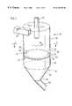
- FIG. 1is an isometric view of a cyclone separator according to the present invention
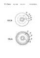
- FIG. 2is a cross-sectional view along the line 2 — 2 in FIG. 1;
- FIGS. 3 a - 3 care cross-sectional views along the line 2 — 2 in FIG. 1 showing various configurations of the particle separation member of the present invention
- FIGS. 4 a and 4 bare cross-sectional views along the line 2 — 2 in FIG. 1 of the cyclonic flow region in alternate embodiments of the device of FIG. 1;
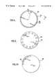
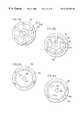
- FIGS. 5-7 aare top plan views of various alternate configurations of the particle separation member of the present invention.
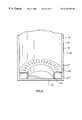
- FIG. 7 bis a side sectional view of a cyclone separator incorporating the particle separation member of FIG. 7 a;
- FIG. 8is a sectional side view of an alternate embodiment of the particle separator member of the present invention.
- FIG. 9is an isometric view of a second alternate embodiment of the particle separator member of the present invention.
- FIG. 10is an isometric view of a third alternate embodiment of the particle separator member of the present invention.
- FIG. 11is an enlarged cross-section view of the particle separator member of the present invention, showing aperture detail
- FIG. 12is a sectional perspective view of the particle separator member having baffle members according to the present invention.
- FIG. 13is an enlarged bottom plan view in the direction of arrow 12 of the baffles of FIG. 12;
- FIG. 14is a sectional perspective view of and alternate embodiment of the baffle members according to the present invention.
- FIG. 15is a bottom plan view of the baffle members of FIG. 14;
- FIG. 16is an perspective view of a household vacuum cleaner incorporating a cyclone separator according to the present invention.
- FIG. 17is an enlarged perspective view of the bin of FIG. 16 when removed from the vacuum cleaner;
- FIG. 18is an enlarged perspective view of the access member of FIG. 17;
- FIG. 19is an exploded perspective view of a chamber emptying means according to the present invention.
- FIGS. 20 a and 20 bare top plan views of the components of the chamber emptying means of FIG. 19;
- FIGS. 21 a and 21 bare top plan views of the chamber emptying means of FIG. 19, shown in the open and closed positions, respectively;
- FIGS. 22 a and 22 bare top plan views of an alternate embodiment of the components of the chamber emptying means according to the present invention.
- cyclonic separators described hereinmay be used with or in place of cyclonic separation devices of any sort which are used to separate particulate material from a fluid stream.
- a fluid streamconsisting of one or more gasses
- industrial dust collection systemseg. flue gas scrubbing
- theymay be used to classify particles according to their size or they may be used with a fluid stream consisting of one or more liquids (eg. a hydrocyclone) or with fluid streams comprising a gas/liquid mixture.
- these cyclone separatorsmay be used in any manner known in the particle separation art.
- separator 30has a bin 32 , an inlet 34 for delivering a cyclonic fluid flow to separator 30 and an outlet 36 for removing fluid from the separator.
- Inlet 34need not be tangential but may be of any configuration which is capable of providing a cyclonic fluid flow to bin 32 , such as an axial or screw cyclone inlet.
- Disposed in a lower portion of bin 32is a separation member 40 which comprises a flat, disc-like member, having an upper face 42 and a lower face 44 , and which substantially divides bin 32 into a cyclone chamber 46 , having a cyclonic flow region 48 defined therein, and a particle receiving chamber 50 .
- Cyclone chamber 46 and particle receiving chamber 50communicate only via a plurality of apertures 52 in separation member 40 .
- Apertures 52comprise a plurality of slits 54 , each having an upstream edge 56 and a downstream edge 58 relative to the direction of cyclonic fluid flow in cyclone chamber 46 (arrow C), longer than the transverse width and oriented generally radially with respect to bin 32 .
- Particle receiving chamber 50comprise a hopper 60 having a sloping wall 62 leading to a hopper exit 64 . Hopper exit 64 communicates with a particle transport conduit 66 for transporting received particles away from receiving chamber 50 .
- a particle-laden fluid streamis introduced to cyclone chamber 46 via inlet 34 to flow cyclonically therein.
- the cyclonic flowproceeds rotationally around and downwardly through bin 32 until it comes into contact with separation member 40 .
- the fluid flowthen proceeds cyclonically upwardly through a central portion of cyclonic flow region 48 in cyclone chamber 46 and is ultimately removed from cyclone chamber 46 via outlet 36 .
- As the cyclonic fluid flowmoves cyclonically down along the inner wall of cyclone chamber 46 , it encounters separation member 40 and travels across separation member 40 .
- the changeis speed and direction of the fluid stream as it flows through cyclone chamber 46 causes particles entrained in the fluid stream to become disentrained.
- These separated particlesmay fall downwardly due to gravity and/or the may be dragged by the fluid stream to upper surface 42 .
- As the separated particles encounter an aperture 52they tend to travel through such aperture (depending on particle size) and are transported away from cyclone chamber 46 into particle receiving chamber 50 .
- Some of the fluidwill pass through apertures 52 carrying entrained particulate matter through separation member 40 and/or dragging separated particulate matter through separation member 40 .
- Hopper 60collects these particles for removal by transport conduit 66 (such as due to gravity flow). Larger particles separated from the fluid flow by the cyclonic action and incapable of passing through apertures 52 accumulate on upper surface 42 of separation member 40 .
- separation member 40assist in particle separation in several ways. First, by providing a discontinuous surface, it disrupts the cyclonic flow thus assisting in separating entrained particulate matter from the fluid stream. Secondly, if provides an area (particle receiving chamber 50 ) which is separate from cyclone chamber 46 . If a portion of the fluid stream enters particle receiving chamber 50 , the cyclonic flow may be slowed or terminated thus allowing entrained particulate matter to separate out without the potential for reentrainment.
- cyclone chamber 46may be of any design known in the art.
- inlet 34 and outlet 36may be positioned at any location and the walls of chamber 46 may be of any construction known in the art.
- apertures 52have been found to affect the particle separation characteristics of separation member 40 for a given cyclone configuration and application. Referring to FIG. 2, it has been found that the anti-reentrainment characteristics of separation member 40 are enhanced if apertures 52 are concentrated beneath peripheral portion 70 of cyclonic flow region 48 (see FIG. 3 a ), inner portion 72 of cyclonic flow region 48 (see FIG. 3 b ), or both peripheral portion 70 and inner portion 72 (see FIG. 3 c ) thereby leaving medial portion 74 substantially free from apertures 52 .
- apertures 52are provided beneath medial portion 74 without any means provided in particle receiving chamber 50 for preventing any substantial (and preferably all) cyclonic flow in particle separating chamber 50 , then some of the particulate material in particle separation chamber 50 will be reentrained into the air flow in cyclone chamber 46 . Accordingly, it is preferred that there are no apertures 52 beneath medial portion 74 when there are no means (eg. baffles) to prevent cyclonic flow in particle separation chamber 50 . It will be appreciated that a few apertures 52 may be provided in medial portion 74 without creating substantial reentrainment.
- peripheral portion 70comprises approximately the outermost one quarter of the radial width 76 of cyclonic flow region 48
- inner portion 72comprises approximately the innermost one quarter of the radial width 76 of cyclonic flow region 48
- Medial portion 74therefore comprises half of the radial width 76 .
- cyclone flow region 48has a radial width 76 ′ between member 80 and bin 32 ′.
- Peripheral and inner portions 70 ′ and 72 ′, respectively,are defined in cyclonic flow region 48 ′ as described above, this time with reference to radial width 76 ′.
- bin 32 ′′may have a non-cross sectional cross-section (eg. elliptical). Accordingly, the shape of cyclonic flow region 48 ′′, peripheral portion 70 ′′ and inner portion 72 ′′ are also elliptical. Thus, the peripheral portion 70 ′′ and inner portion 72 ′′ will have portions having different radial widths.
- the cyclonemay alternately have any non-curvilinear cross-section which permits a substantially cyclonic flow therein.
- the radial width of cyclone chamber 46may vary along its longitudinal length, and may be, eg., cylindrical, frusto-conical or any other shape having beneficial cyclonic particle separation characteristics.
- Apertures 52may be of any particular shape. For example, they may be circular (see FIG. 6 ), rectangular (see FIG. 12 ), triangular, or other regular or irregular shape. While apertures 52 may be any shape, in a preferred embodiment, they have a length greater than their width. In particular, as shown in FIG. 12, upstream and downstream edges 58 , 60 are preferably longer than the spaced opposed sides 57 extending between edges 58 , 60 (eg. edges 58 , 60 are preferably at least twice the length of sides 57 ) so that apertures 52 define slits.
- slits 54may extend generally radially (i.e. edges 58 , 60 may extend generally radially). However, as shown in FIG. 5, slits 54 are preferably angled slightly, relative to radial width 76 , so that the outer edge 82 of an aperture 52 is upstream of the inner edge 84 , relative to the cyclonic air flow (indicated by arrow C). The angle a of slits 54 relative to radial width 76 may be up to 45°.
- Apertures 52may be equidistantly spaced apart around separation member 40 (see FIGS. 3 a - 3 c ) or they may be positioned with different spacings between adjacent apertures 52 . Further, apertures 52 may be continuously positioned around all of separation member 40 (see FIGS. 3 a - 3 c ) or apertures 52 may be positioned around only a portion of separation member 40 (see FIG. 7 a ). Distributing apertures 52 over only a region may be beneficial where only a portion of dirt separation member 40 is contacted by the cyclonic flow in bin 32 (see FIG. 7 b ). This may be used, for example, if bin 32 has a single inlet 34 . In such a case, the sector of separation member 40 which will be contacted by the cyclonic flow may be predetermined and apertures 52 provided only in that sector.
- dust separation member 40need not be positioned perpendicular to the cyclonic (ie. longitudinal) axis of cyclonic flow region 48 in cyclone chamber 46 .
- separation member 40may be at an angle to the axis.
- separation member 40need not extend across the entirety of cyclonic flow region 48 , but rather may be disposed in only the portion of cyclonic flow region 48 beneath which apertures 52 are to be provided.
- FIG. 8shows a separation member 40 ′′′ which comprises an annular ring 86 disposed beneath peripheral portion 70 of cyclonic flow region 48 .
- Particle receiving chamber 50 ′′′is disposed thereunder, between bin 32 and an inner wall 88 .
- separation member 40may equally have any other configuration suitable for a given separator application without departing from the scope of the present invention. It will be appreciated, for example, that separator 40 may comprise an annular ring positioned beneath inner portion 72 of cyclonic flow region 48 .
- separation member 40need not be disc-shaped, but may also be conical or trumpet-shaped. It may be convex (i.e. it may project into particle receiving chamber 50 as shown in FIG. 10) or it may be concave (i.e. it may project away from particle receiving chamber 50 ). It will be appreciated that separation member 40 need not define a continuous surface. For example, as shown in FIG. 10, it may have a curved surface in which apertures 52 are provided and a flat central top portion 78 .
- Particle receiving chamber 50need not have hopper 60 thereunder. Instead, it may have a substantially closed bottom 90 , as shown in FIGS. 9 and 10. In this configuration, particles received by particle receiving chamber 50 are collected therein for subsequent emptying, as described below. This configuration may be used in a batch process operation.
- edges 56 and 58may be aerodynamically shaped to enhance the performance of separation member 40 .
- the thickness of particle separating member 40is preferably reduced adjacent the upstream edge 56 .
- aperture 52has a sloped upstream edge 56 to assist in directing air and particles from cyclone chamber 46 to particle receiving chamber 50 . While either or both of upper surface 42 and lower surface 44 may be sloped with respect to the plane in which particle separation member 40 lies, it is preferred that upper surface 42 is sloped. It has been found that an angle of 45° is preferable.
- the thickness of downstream edge 58 of particle separating member 40may be substantially unchanged.
- aperture 52is preferably shaped to have sloped downstream edge 58 to assist in directing air and particles from cyclone chamber 46 to particle receiving chamber 50 . Performance is further enhanced if downstream edge 58 has a blunt surface 92 on an upper portion thereof. Other edge configurations may also be beneficially employed.
- particle receiving chamber 50may be provided with a plurality of baffles 100 .
- the bafflesoperate to reduce and preferably stop the cyclonic flow of air beneath particle separation member 40 .
- baffles 100extend from lower surface 44 towards bottom 90 but do not touch bottom 90 .
- Baffles 100preferably extend approximately three-quarters of the distance from lower surface 44 of separation member 40 to the bottom 90 of particle receiving chamber 50 , but may be longer or shorter if desired.
- baffles 100are parallel to the longitudinal axis of cyclone bin 32 .
- a baffle 100is preferably disposed adjacent each aperture 52 on the downstream side, relative to cyclonic flow in cyclonic chamber 46 (arrow C).
- a baffle 100may be offset 15° downstream from its associated aperture 52 . It will be appreciated that a baffle 100 need not be associated with each aperture 52 . Preferably the baffles are immediately downstream of each aperture 52 .
- Baffles 100comprises a wall 102 which may extend radially inwardly or which may be curved.
- wall 102is substantially parallel to aperture 52 along its length.
- Wall 102extends at least coterminously with the length of edges 56 , 58 apertures 52 .
- wallextends at least three times the length of edges 56 , 58 .
- baffle 100may also have a lateral wall 104 disposed adjacent outer and/or inner edges 82 and 84 of aperture 52 .
- Wall 104preferably extends from wall 102 in the upstream direction. If an apertures 52 is disposed in peripheral portion 70 , baffle 100 preferable has one lateral wall 104 only, disposed adjacent inner edge 84 . Wall 102 is positioned inward of edge 84 so as to define a dead air space beneath aperture 52 . If an aperture 52 is located in inner portion 72 , baffle 100 preferably has a lateral wall 104 disposed adjacent inner edge 84 and outer edge 82 of aperture 52 (not shown). Walls 104 may thus effectively define an open central area in particle receiving chamber 50 .
- Baffles 100configured as a wall 102 alone or in conjunction with a lateral wall 104 , reduce and preferably stop the cyclonic nature of the fluid flowing beneath separation member 40 .
- baffles 100may extend from the wall of bin 32 to its centre to effectively divide particle receiving chamber 50 into a plurality of pie-shaped compartments 106 within particle receiving chamber 50 . This configuration substantially inhibits any fluid flow, cyclonic or otherwise, within compartments 106 , thereby beneficially enhancing the anti-reentrainment of characteristics of separation member 40 .
- apertures 52may be positioned at any location along the radial width of particle separation member 40 and may be disposed in nay one or more of inner portion 72 , medial portion 74 and peripheral portion 70 of cyclonic flow region 48 .
- the particle separation membermay be used with a cyclone separator for a vacuum cleaner. While separator 30 may be used in any vacuum cleaner (eg. upright, canister or a central vacuum cleaning system), it will be described as it may be used in an upright vacuum cleaner.
- any vacuum cleanereg. upright, canister or a central vacuum cleaning system
- vacuum cleaner 200has a floor cleaning head 202 , means for moving cleaning head 202 across a floor (eg. wheels 204 ), main casing 206 rotatably attached to cleaner head 202 , and a handle 208 for moving cleaner 200 across the floor.
- Main casing 206houses separator 30 .
- a single separator 30comprises a central air feed conduit 210 in communication with a air nozzle (not shown) adjacent the floor in cleaner head 202 , and leading to a curved air inlet 34 .
- bin 32is removable from main casing 206 , via the application of pressure by the hand of a user to handle 212 .
- Bin 32has an open end 214 and defines a cyclone chamber 46 and particle receiving chamber 50 therein.
- Separation member 40has a plurality of apertures 52 disposed in peripheral portion 70 thereof.
- An air outletis disposed centrally in an upper portion of cyclone chamber 46 .
- an air flowis created by a motor (not shown) in vacuum cleaner 200 to draw air from, eg., the nozzle of cleaner head 202 , through centre air feed conduit 210 and into cyclone chamber 46 via inlet 34 .
- Cyclonic flowis maintained in cyclone chamber 46 thereby causing particles entrained in the cyclonic flow to be deposited, with smaller particles passing through apertures 52 into particle receiving chamber 50 , while larger particles (eg. elongate particles such as hair, carpet fibres and the like) are deposited on upper surface 42 .
- Airthen exits cyclone chamber via air outlet 36 , though the motor and then exits the cleaner. The finer dirt tends to be separated and deposited in particle receiving chamber 50 .
- bin 32is removed from main casing 206 , via, eg., handle 212 , and inverted (typically over a refuse collector of the like) to cause the collected particles on upper face 42 to fall from bin 32 under the influence of gravity.
- a door or the likeis preferably provided to assist in emptying chamber 50 .
- the doormay be provided on the outer wall of bin 32 .
- particle separation member 40is constructed to assist in emptying the contents of particle receiving chamber 50 when bin 32 is inverted.
- particle separation member 40may be constructed to provide an opening when bin 32 is inverted (see for example FIGS. 17 and 18) or a door may be provided in particle separation member 32 prior to inverting bin 32 (see for example FIGS. 19, 20 a , 20 b , 21 a , 21 b , 22 a and 22 b ).
- separation member 40may comprise a main body 110 and an access member 112 , as shown in FIG. 18 .
- Access member 112comprises a chord section of separation member 40 pivotally connected to main body 110 by a hinge member 114 to swing between a closed position, substantially planar with main body 110 (as represented by the solid lines in FIGS. 17 and 18) and an open position, wherein access member 112 swings upwardly relative to main body 110 (as represented by the broken lines in FIGS. 17 and 18 ).
- access member 112when bin 32 is removed from vacuum cleaner 200 and inverted, access member 112 , by virtue of its pivoting connection to main body 110 , is permitted to freely swings to its “open” position under the influence of gravity, thereby permitting the contents of particle receiving chamber 50 to fall from particle receiving chamber 50 and out of bin 32 .
- the access member 112When bin 32 is returned to its upright position, the access member 112 falls to its closed position under the influence of gravity.
- access member 112may optionally be provided with a weight 116 , or a suitable spring means (not shown) or other biasing means known to those skilled in the art.
- Hole 118is provided to permit centre air feed conduit 210 to pass there through.
- the direction of the pivot axis 218 of hinge member 114is preferably selected to assist access member 112 to remain closed while the vacuum cleaner is in use. If the vacuum cleaner is an upright vacuum cleaner, then particle separation member 40 will be moved from a generally horizontally disposed position when main casing 206 is in the upright storage position to an inclined position when main casing 206 is pivoted to the in use position.
- Access member 112has a pivot axis 218 which is preferably not parallel to pivot axis 216 of the upper casing 206 of the vacuum cleaner. In such a case, no weight may be required.
- pivot axis 218 of access member 112is at an angle ⁇ of 10-50°, preferably 20° to 40°, and more preferably about 30° to the pivot axis 216 of upper casing 206 (see FIG. 17 ).
- Access member 112is preferably provided in the rear portion of the cyclone bin 32 to prevent access member 112 from opening during use.
- all or a major portion of access member 122is preferably positioned rearward of centre air feed 210 (ie. towards handle 208 ). In such a case, no weight may be required.
- separation member 40comprises an first member 120 and a second member 122 .
- First member 120has a plurality of openings 124 .
- Second member 122a plurality of solid members 126 spaced apart by open areas 128 .
- First and second members 120 and 122are configured and sized such that, when first member 120 is positioned immediately above second member 122 , first and second members are positionable between a first, “open” position, wherein openings 124 and open areas 128 are substantially aligned (see FIG. 21 a ), and a second, “closed” position, wherein openings 124 and open areas 128 are offset, such that solid members 126 substantially close openings 124 (see FIG. 21 b ).
- openings 124 and open areas 128provide a plurality of access ports 132 from particle receiving chamber 50 to cyclone chamber 46 (see FIG. 21 a ).
- Separation member 40must be provided with apertures 52 .
- Apertures 52may be provided as openings in first member 120 such as were discussed with respect to FIG. 1 .
- apertures 52may be created by constructing members 120 and 122 to leave apertures 52 when they are in the closed position.
- solid members 126may be rotatably so as to only substantially underlie and block openings 124 so as to create a plurality of openings which function as apertures 52 in separation member 40 .
- solid members 126may have recessed portions 134 provided therein (see FIG. 20 b ) so that when solid member 126 fully underlies openings 124 , a plurality of holes 130 are created (see FIG. 21 b ).
- first member 120 and second member 122are in their “closed” position, such that a plurality of apertures 52 are defined in separation member 40 .
- apertures 52perform a function substantially as described above.
- bin 32is removed from main casing 206 of vacuum cleaner 200 , as described above, and first and second members 120 and 122 are moved to their “open” position, thereby opening access ports 132 .
- the binis then inverted to empty the collected contents and access ports 132 permit the separated particles in particle receiving chamber 50 to exit into cyclone chamber 46 and out of bin 32 .
- bin 32 and chamber 50may be emptied at the same time.
- First and second members 120 and 122are then returned to their “closed” position, and the bin returned to main casing 206 , to ready vacuum cleaner 200 for further operation.
- first and second members 120 and 122 from their “closed” to “open” positionsmay be automated. This may be achieved by any means known in the art. For example, such movement may be linked to the removal of bin 32 from main casing 206 , such that removal of the bin causes first and second members 120 and 122 to move from their “closed” to “open” positions without further action by the user.
- bin 32is bayonet-mounted (not shown) in main casing 206 such bin 32 must be rotated about its longitudinal axis before bin 32 may be removed from main casing 206 .
- a bayonet-type mechanism(not shown), as is known in the art, triggers a movement of first and second members 120 and 122 from the “closed” to “open” positions, thereby automatically opening separation member 40 in preparation for emptying.
- member 120may be affixed to the inner wall of bin 32 and centre air feed 210 may freely rotate within hole 118 .
- Centre air feed 210may be rotatably mounted in bin 32 so as not to rotate as bin 32 is rotated for removal and member 122 may be affixed to centre air feed 210 .
- member 120rotates with bin 32 relative to member 122 to move separation member 40 to the “open” position.
- a trip-lever mechanism(not shown) may be used such that a horizontal translational movement of bin 32 out of main casing 206 trips a lever which causes first and second members 120 and 122 to move from the “closed” to “open” positions, thereby automatically opening separation member 40 in preparation for emptying.
- a trip-lever mechanism(not shown) may be used such that a horizontal translational movement of bin 32 out of main casing 206 trips a lever which causes first and second members 120 and 122 to move from the “closed” to “open” positions, thereby automatically opening separation member 40 in preparation for emptying.
- Yet other methods of automatically moving second member 122 upon removal of bin 32may be devised.
- first and second members 120 and 122may be of any configuration which provides “closed” and “open” positions, as described above.
- first and second members 120 and 122may be substantially identically shaped (see FIGS. 22 a-b ). It will be understood by one skilled in the art that first member 120 and second member 122 need not move rotationally with respect to one another, but may also move radially or translationally.
- the separation member according to the present inventionmay also be employed in the classification and/or sorting of particles by size.
- Particles to be sortedare entrained in a fluid flow and introduced to a cyclonic separator having a separation member according to the present invention, the separation member having a first aperture size.
- Particles smaller than the first aperture sizeare permitted to pass through the separation member and into a hopper for transfer to a subsequent cyclonic separator while larger particles are collected on top of the particle separator.
- the particle passing through the separation memberare introduced cyclonically to a second cyclone having a separation member with apertures of a second, smaller size, relative to the first cyclone.
- particles smaller than the second aperture sizeare permitted to pass through the separation member and into a hopper for transfer to a third cyclonic separator, while larger particle remain on the separation member in the second cyclone chamber. This process is repeated, as required, until the particles are classified as needed.
- the introduction of the separation member according to the present invention to a cyclonic separatordramatically increases the overall efficiency of the separator.
- the prior artteaches the need for a plurality of cyclones in order achieve ultra-high particle separation efficiencies.
- ultra-high efficienciescan be obtained in a single stage cyclone incorporating the particle separation member of the present invention.
- Cleaning efficiencies in excess of 95%may be obtained with a single stage separator utilizing the separation member according to the present invention, thereby negating the need for second stage cyclonic separation altogether.
- Cleaning efficiencies of over 99%have also been achieved for particle laden air streams.
- the present inventionpermits ultra-high efficiencies to be attained with relatively simple separator configurations compared to the prior art.
- the reduction of separator structurebeneficially reduces the fluid pressure losses across the separator, thereby permits a deeper vacuum (increased fluid flow rate) to be drawn for a given motor size.
- the motor sizemay be reduced without sacrificing the vacuum strength of the device.
- the reduced structure and motor sizealso beneficially result in a cost and size savings to the overall separator unit.
- baffle members according to the present inventiongreatly enhance the performance of the separation member and greatly assist in obtaining ultra-high efficiencies.
- the projection of baffle members into the particle receiving chamberbeneficially disrupts and, depending on the baffle configuration, substantially inhibits cyclonic flow in the particle receiving chamber, thereby reducing the reentrainment of deposited particles.
- the separation member access meansprovides a simple and convenient method of emptying collected particles from two chambers simultaneously, namely larger particles deposited in the cyclone chamber (i.e. on top of the particle separation member) and finer particles deposited in the particle receiving chamber. This provides a simple and convenient automatic method of emptying dual chambers.
- the superimposed particle separation member according to the present inventionalso provides a convenient method for emptying collected particles from two chambers simultaneously. To enhance the convenience, the movement of the superimposed members may be linked to open when the bin is removed from the main casing.
Landscapes
- Engineering & Computer Science (AREA)
- Mechanical Engineering (AREA)
- Cyclones (AREA)
Abstract
Description
Claims (34)
Priority Applications (6)
| Application Number | Priority Date | Filing Date | Title |
|---|---|---|---|
| US09/361,128US6228260B1 (en) | 1999-07-27 | 1999-07-27 | Apparatus for separating particles from a cyclonic fluid flow |
| US09/482,649US6440197B1 (en) | 1999-07-27 | 2000-01-13 | Apparatus and method separating particles from a cyclonic fluid flow including an apertured particle separation member within a cyclonic flow region |
| PCT/CA2000/000873WO2001007168A1 (en) | 1999-07-27 | 2000-07-26 | Apparatus and method for separating particles from a cyclonic fluid flow |
| US10/030,108US6874197B1 (en) | 1999-07-27 | 2000-07-26 | Apparatus and method for separating particles from a cyclonic fluid flow |
| US11/019,684US7449040B2 (en) | 1999-07-27 | 2004-12-23 | Apparatus and method for separating particles from a cyclonic fluid flow |
| US12/248,954US7588616B2 (en) | 1999-07-27 | 2008-10-10 | Vacuum cleaner with a plate and an openable dirt collection chamber |
Applications Claiming Priority (1)
| Application Number | Priority Date | Filing Date | Title |
|---|---|---|---|
| US09/361,128US6228260B1 (en) | 1999-07-27 | 1999-07-27 | Apparatus for separating particles from a cyclonic fluid flow |
Related Parent Applications (2)
| Application Number | Title | Priority Date | Filing Date |
|---|---|---|---|
| US09/361,124Continuation-In-PartUS6221134B1 (en) | 1999-07-27 | 1999-07-27 | Apparatus and method for separating particles from a cyclonic fluid flow |
| US09/361,124ContinuationUS6221134B1 (en) | 1999-07-27 | 1999-07-27 | Apparatus and method for separating particles from a cyclonic fluid flow |
Related Child Applications (2)
| Application Number | Title | Priority Date | Filing Date |
|---|---|---|---|
| US09/482,648Continuation-In-PartUS6326681B1 (en) | 1988-09-20 | 2000-01-13 | Semiconductor device |
| US09/482,649Continuation-In-PartUS6440197B1 (en) | 1999-07-27 | 2000-01-13 | Apparatus and method separating particles from a cyclonic fluid flow including an apertured particle separation member within a cyclonic flow region |
Publications (1)
| Publication Number | Publication Date |
|---|---|
| US6228260B1true US6228260B1 (en) | 2001-05-08 |
Family
ID=23420765
Family Applications (1)
| Application Number | Title | Priority Date | Filing Date |
|---|---|---|---|
| US09/361,128Expired - LifetimeUS6228260B1 (en) | 1999-07-27 | 1999-07-27 | Apparatus for separating particles from a cyclonic fluid flow |
Country Status (1)
| Country | Link |
|---|---|
| US (1) | US6228260B1 (en) |
Cited By (131)
| Publication number | Priority date | Publication date | Assignee | Title |
|---|---|---|---|---|
| US20030066156A1 (en)* | 2001-10-09 | 2003-04-10 | Lg Electronics Inc. | Dust collection unit for use in vacuum cleaner and main body of vacuum cleaner having the same |
| US20040010885A1 (en)* | 2002-07-18 | 2004-01-22 | Hitzelberger J. Erik | Dirt container for cyclonic vacuum cleaner |
| US20040103784A1 (en)* | 2002-12-03 | 2004-06-03 | Birdwell Gaylon W. | Sand/dust filtering system |
| US20040177472A1 (en)* | 2003-03-10 | 2004-09-16 | Lg Electronics Inc. | Dust collecting unit of vacuum cleaner |
| US6874197B1 (en)* | 1999-07-27 | 2005-04-05 | G.B.D Corp | Apparatus and method for separating particles from a cyclonic fluid flow |
| US20050241101A1 (en)* | 2000-01-14 | 2005-11-03 | Sepke Arnold L | Bagless dustcup |
| US20060070207A1 (en)* | 2000-01-14 | 2006-04-06 | Thomas Hawkins | Upright vacuum cleaner with cyclonic air path |
| US20060137302A1 (en)* | 2004-12-27 | 2006-06-29 | Lg Electronics, Inc. | Cyclomic dust collection unit filter structure thereof |
| US20060235896A1 (en)* | 2005-04-14 | 2006-10-19 | Konica Minolta Business Technologies, Inc. | Information processing apparatus easy for users to operate |
| US20070209339A1 (en)* | 2006-03-10 | 2007-09-13 | Gbd Corp. | Vacuum cleaner with a plurality of cyclonic cleaning stages |
| US20070267342A1 (en)* | 2006-05-22 | 2007-11-22 | Contech Stormwater Solutions, Inc. | Apparatus for separating particulate from stormwater |
| US20080115469A1 (en)* | 2005-07-26 | 2008-05-22 | Brian Lane | Separator assembly |
| US20080196194A1 (en)* | 2006-12-12 | 2008-08-21 | G.B.D. Corp. | Surface cleaning apparatus with off-centre dirt bin inlet |
| US20080216282A1 (en)* | 2007-03-09 | 2008-09-11 | G.B.D. Corp. | Surface cleaning apparatus with enlarged dirt collection chamber |
| WO2010008431A1 (en)* | 2008-07-17 | 2010-01-21 | Kellogg Brown & Root Llc | Direct stripping cyclone |
| US8398751B2 (en) | 2008-07-17 | 2013-03-19 | Kellogg Brown & Root Llc | Direct stripping cyclone |
| WO2013184814A1 (en)* | 2012-06-07 | 2013-12-12 | The Regents Of The University Of California | Crossflow filtration particle separator |
| US8776309B2 (en) | 2010-03-12 | 2014-07-15 | G.B.D. Corp. | Cyclone construction for a surface cleaning apparatus |
| US20150020732A1 (en)* | 2013-02-04 | 2015-01-22 | Nordson Corporation | Powder coating system having powder recovery cyclone with hinged lower section |
| US9015899B2 (en) | 2009-03-13 | 2015-04-28 | G.B.D. Corp. | Surface cleaning apparatus with different cleaning configurations |
| US9027198B2 (en) | 2013-02-27 | 2015-05-12 | G.B.D. Corp. | Surface cleaning apparatus |
| USD740502S1 (en) | 2014-08-12 | 2015-10-06 | Milwaukee Electric Tool Corporation | Vacuum cleaner |
| US9161669B2 (en) | 2013-03-01 | 2015-10-20 | Omachron Intellectual Property Inc. | Surface cleaning apparatus |
| US9198551B2 (en) | 2013-02-28 | 2015-12-01 | Omachron Intellectual Property Inc. | Surface cleaning apparatus |
| US9204773B2 (en) | 2013-03-01 | 2015-12-08 | Omachron Intellectual Property Inc. | Surface cleaning apparatus |
| US9227151B2 (en) | 2013-02-28 | 2016-01-05 | Omachron Intellectual Property Inc. | Cyclone such as for use in a surface cleaning apparatus |
| US9227201B2 (en) | 2013-02-28 | 2016-01-05 | Omachron Intellectual Property Inc. | Cyclone such as for use in a surface cleaning apparatus |
| US9226633B2 (en) | 2009-03-13 | 2016-01-05 | Omachron Intellectual Property Inc. | Surface cleaning apparatus |
| US9232877B2 (en) | 2010-03-12 | 2016-01-12 | Omachron Intellectual Property Inc. | Surface cleaning apparatus with enhanced operability |
| US9238235B2 (en) | 2013-02-28 | 2016-01-19 | Omachron Intellectual Property Inc. | Cyclone such as for use in a surface cleaning apparatus |
| US9295995B2 (en) | 2013-02-28 | 2016-03-29 | Omachron Intellectual Property Inc. | Cyclone such as for use in a surface cleaning apparatus |
| US9301662B2 (en) | 2006-12-12 | 2016-04-05 | Omachron Intellectual Property Inc. | Upright vacuum cleaner |
| US9301666B2 (en) | 2006-12-12 | 2016-04-05 | Omachron Intellectual Property Inc. | Surface cleaning apparatus |
| US9314139B2 (en) | 2014-07-18 | 2016-04-19 | Omachron Intellectual Property Inc. | Portable surface cleaning apparatus |
| US9314138B2 (en) | 2013-02-28 | 2016-04-19 | Omachron Intellectual Property Inc. | Surface cleaning apparatus |
| US9320401B2 (en) | 2013-02-27 | 2016-04-26 | Omachron Intellectual Property Inc. | Surface cleaning apparatus |
| US9326652B2 (en) | 2013-02-28 | 2016-05-03 | Omachron Intellectual Property Inc. | Surface cleaning apparatus |
| US9364127B2 (en) | 2013-02-28 | 2016-06-14 | Omachron Intellectual Property Inc. | Surface cleaning apparatus |
| US9386895B2 (en) | 2009-03-13 | 2016-07-12 | Omachron Intellectual Property Inc. | Surface cleaning apparatus |
| US9392916B2 (en) | 2009-03-13 | 2016-07-19 | Omachron Intellectual Property Inc. | Surface cleaning apparatus |
| US9420925B2 (en) | 2014-07-18 | 2016-08-23 | Omachron Intellectual Property Inc. | Portable surface cleaning apparatus |
| US9427122B2 (en) | 2009-03-13 | 2016-08-30 | Omachron Intellectual Property Inc. | Surface cleaning apparatus |
| US9427126B2 (en) | 2013-03-01 | 2016-08-30 | Omachron Intellectual Property Inc. | Surface cleaning apparatus |
| US9433332B2 (en) | 2013-02-27 | 2016-09-06 | Omachron Intellectual Property Inc. | Surface cleaning apparatus |
| US9451853B2 (en) | 2014-07-18 | 2016-09-27 | Omachron Intellectual Property Inc. | Portable surface cleaning apparatus |
| US9451852B2 (en) | 2009-03-13 | 2016-09-27 | Omachron Intellectual Property Inc. | Surface cleaning apparatus with different cleaning configurations |
| US9451855B2 (en) | 2013-02-28 | 2016-09-27 | Omachron Intellectual Property Inc. | Surface cleaning apparatus |
| EP2612584A4 (en)* | 2010-08-30 | 2016-09-28 | Panasonic Corp | DUST COLLECTOR AND ELECTRIC VACUUM CLEANER |
| US9456721B2 (en) | 2013-02-28 | 2016-10-04 | Omachron Intellectual Property Inc. | Surface cleaning apparatus |
| US20160287041A1 (en)* | 2006-12-15 | 2016-10-06 | Omachron Intellectual Property Inc. | Surface cleaning apparatus |
| US9480373B2 (en) | 2009-03-13 | 2016-11-01 | Omachron Intellectual Property Inc. | Surface cleaning apparatus |
| US9585530B2 (en) | 2014-07-18 | 2017-03-07 | Omachron Intellectual Property Inc. | Portable surface cleaning apparatus |
| US9591952B2 (en) | 2009-03-11 | 2017-03-14 | Omachron Intellectual Property Inc. | Hand vacuum cleaner with removable dirt chamber |
| US9591953B2 (en) | 2009-03-13 | 2017-03-14 | Omachron Intellectual Property Inc. | Surface cleaning apparatus |
| US9591958B2 (en) | 2013-02-27 | 2017-03-14 | Omachron Intellectual Property Inc. | Surface cleaning apparatus |
| CN106823715A (en)* | 2017-03-03 | 2017-06-13 | 北京朗净时代环境科技有限公司 | A kind of pair of cyclone desulfurization synergistic device and a kind of multistage double cyclone desulfurization synergistic devices |
| US9693666B2 (en) | 2011-03-04 | 2017-07-04 | Omachron Intellectual Property Inc. | Compact surface cleaning apparatus |
| US9693665B2 (en) | 2014-10-22 | 2017-07-04 | Techtronic Industries Co. Ltd. | Vacuum cleaner having cyclonic separator |
| US9775483B2 (en) | 2014-10-22 | 2017-10-03 | Techtronic Industries Co. Ltd. | Vacuum cleaner having cyclonic separator |
| US9820621B2 (en) | 2013-02-28 | 2017-11-21 | Omachron Intellectual Property Inc. | Surface cleaning apparatus |
| US9826868B2 (en) | 2009-03-13 | 2017-11-28 | Omachron Intellectual Property Inc. | Portable surface cleaning apparatus |
| US9885194B1 (en) | 2017-05-11 | 2018-02-06 | Hayward Industries, Inc. | Pool cleaner impeller subassembly |
| US9885196B2 (en) | 2015-01-26 | 2018-02-06 | Hayward Industries, Inc. | Pool cleaner power coupling |
| US9888817B2 (en) | 2014-12-17 | 2018-02-13 | Omachron Intellectual Property Inc. | Surface cleaning apparatus |
| US9896858B1 (en) | 2017-05-11 | 2018-02-20 | Hayward Industries, Inc. | Hydrocyclonic pool cleaner |
| US9909333B2 (en) | 2015-01-26 | 2018-03-06 | Hayward Industries, Inc. | Swimming pool cleaner with hydrocyclonic particle separator and/or six-roller drive system |
| US9949601B2 (en) | 2007-08-29 | 2018-04-24 | Omachron Intellectual Property Inc. | Cyclonic surface cleaning apparatus |
| US9962050B2 (en) | 2016-08-29 | 2018-05-08 | Omachron Intellectual Property Inc. | Surface cleaning apparatus |
| US10016106B1 (en) | 2016-12-27 | 2018-07-10 | Omachron Intellectual Property Inc. | Multistage cyclone and surface cleaning apparatus having same |
| US10080472B2 (en) | 2010-03-12 | 2018-09-25 | Omachron Intellectual Property Inc. | Hand carriable surface cleaning apparatus |
| US10117551B2 (en) | 2014-10-22 | 2018-11-06 | Techtronic Industries Co. Ltd. | Handheld vacuum cleaner |
| US10136780B2 (en) | 2016-08-29 | 2018-11-27 | Omachron Intellectual Property Inc. | Surface cleaning apparatus |
| US10136778B2 (en) | 2014-12-17 | 2018-11-27 | Omachron Intellectual Property Inc. | Surface cleaning apparatus |
| US10136779B2 (en) | 2016-08-29 | 2018-11-27 | Omachron Intellectual Property Inc. | Surface cleaning apparatus |
| US10156083B2 (en) | 2017-05-11 | 2018-12-18 | Hayward Industries, Inc. | Pool cleaner power coupling |
| US10165912B2 (en) | 2006-12-15 | 2019-01-01 | Omachron Intellectual Property Inc. | Surface cleaning apparatus |
| WO2019030493A1 (en)* | 2017-08-11 | 2019-02-14 | Dyson Technology Limited | Dirt separator for a vacuum cleaner |
| US10251519B2 (en) | 2014-12-17 | 2019-04-09 | Omachron Intellectual Property Inc. | Surface cleaning apparatus |
| US10258210B2 (en) | 2016-12-27 | 2019-04-16 | Omachron Intellectual Property Inc. | Multistage cyclone and surface cleaning apparatus having same |
| US10271704B2 (en) | 2016-12-27 | 2019-04-30 | Omachron Intellectual Property Inc. | Multistage cyclone and surface cleaning apparatus having same |
| US10292550B2 (en) | 2016-08-29 | 2019-05-21 | Omachron Intellectual Property Inc. | Surface cleaning apparatus |
| US10299643B2 (en) | 2016-12-27 | 2019-05-28 | Omachron Intellectual Property Inc. | Multistage cyclone and surface cleaning apparatus having same |
| US10299649B2 (en) | 2013-02-28 | 2019-05-28 | Omachron Intellectual Property Inc. | Surface cleaning apparatus |
| US10321794B2 (en) | 2016-08-29 | 2019-06-18 | Omachron Intellectual Property Inc. | Surface cleaning apparatus |
| US10405709B2 (en) | 2016-12-27 | 2019-09-10 | Omachron Intellectual Property Inc. | Multistage cyclone and surface cleaning apparatus having same |
| US10405711B2 (en) | 2016-08-29 | 2019-09-10 | Omachron Intellectual Property Inc. | Surface cleaning apparatus |
| US10413141B2 (en) | 2016-08-29 | 2019-09-17 | Omachron Intellectual Property Inc. | Surface cleaning apparatus |
| US10420867B2 (en) | 2015-10-19 | 2019-09-24 | Conmed Corporation | Liquid-gas Separator |
| US10433686B2 (en) | 2007-08-29 | 2019-10-08 | Omachron Intellectual Property Inc. | Configuration of a surface cleaning apparatus |
| US10433689B2 (en) | 2016-08-29 | 2019-10-08 | Omachron Intellectual Property Inc. | Surface cleaning apparatus |
| US10441125B2 (en) | 2016-08-29 | 2019-10-15 | Omachron Intellectual Property Inc. | Surface cleaning apparatus |
| US10441124B2 (en) | 2016-08-29 | 2019-10-15 | Omachron Intellectual Property Inc. | Surface cleaning apparatus |
| US10506904B2 (en) | 2017-07-06 | 2019-12-17 | Omachron Intellectual Property Inc. | Handheld surface cleaning apparatus |
| US10537216B2 (en) | 2017-07-06 | 2020-01-21 | Omachron Intellectual Property Inc. | Handheld surface cleaning apparatus |
| US10631697B2 (en) | 2014-02-14 | 2020-04-28 | Techtronic Industries Co. Ltd. | Separator configuration |
| US10631693B2 (en) | 2017-07-06 | 2020-04-28 | Omachron Intellectual Property Inc. | Handheld surface cleaning apparatus |
| US10702113B2 (en) | 2017-07-06 | 2020-07-07 | Omachron Intellectual Property Inc. | Handheld surface cleaning apparatus |
| US10722086B2 (en) | 2017-07-06 | 2020-07-28 | Omachron Intellectual Property Inc. | Handheld surface cleaning apparatus |
| US10729295B2 (en) | 2016-08-29 | 2020-08-04 | Omachron Intellectual Property Inc. | Surface cleaning apparatus |
| US10750913B2 (en) | 2017-07-06 | 2020-08-25 | Omachron Intellectual Property Inc. | Handheld surface cleaning apparatus |
| US10765277B2 (en) | 2006-12-12 | 2020-09-08 | Omachron Intellectual Property Inc. | Configuration of a surface cleaning apparatus |
| DE102016116813B4 (en)* | 2015-09-15 | 2020-10-22 | Fanuc Corporation | Laser oscillator with a heat exchanger with the function of trapping foreign objects |
| US10827891B2 (en) | 2016-12-27 | 2020-11-10 | Omachron Intellectual Property Inc. | Multistage cyclone and surface cleaning apparatus having same |
| US10842330B2 (en) | 2017-07-06 | 2020-11-24 | Omachron Intellectual Property Inc. | Handheld surface cleaning apparatus |
| US11006799B2 (en) | 2018-08-13 | 2021-05-18 | Omachron Intellectual Property Inc. | Cyclonic air treatment member and surface cleaning apparatus including the same |
| US11013378B2 (en) | 2018-04-20 | 2021-05-25 | Omachon Intellectual Property Inc. | Surface cleaning apparatus |
| US11013384B2 (en) | 2018-08-13 | 2021-05-25 | Omachron Intellectual Property Inc. | Cyclonic air treatment member and surface cleaning apparatus including the same |
| US11192122B2 (en) | 2018-08-13 | 2021-12-07 | Omachron Intellectual Property Inc. | Cyclonic air treatment member and surface cleaning apparatus including the same |
| US11246462B2 (en) | 2019-11-18 | 2022-02-15 | Omachron Intellectual Property Inc. | Multi-inlet cyclone |
| US11285495B2 (en) | 2016-12-27 | 2022-03-29 | Omachron Intellectual Property Inc. | Multistage cyclone and surface cleaning apparatus having same |
| US11284761B2 (en) | 2016-10-14 | 2022-03-29 | Techtronic Floor Care Technology Limited | Cyclonic separation device |
| US11445878B2 (en) | 2020-03-18 | 2022-09-20 | Omachron Intellectual Property Inc. | Surface cleaning apparatus with removable air treatment member assembly |
| US11478117B2 (en) | 2016-08-29 | 2022-10-25 | Omachron Intellectual Property Inc. | Surface cleaning apparatus |
| US11612288B2 (en) | 2009-03-13 | 2023-03-28 | Omachron Intellectual Property Inc. | Surface cleaning apparatus |
| US11666193B2 (en) | 2020-03-18 | 2023-06-06 | Omachron Intellectual Property Inc. | Surface cleaning apparatus with removable air treatment member assembly |
| US11690489B2 (en) | 2009-03-13 | 2023-07-04 | Omachron Intellectual Property Inc. | Surface cleaning apparatus with an external dirt chamber |
| US11723501B2 (en) | 2018-08-09 | 2023-08-15 | Milwaukee Electric Tool Corporation | Handheld vacuum cleaner |
| US11730327B2 (en) | 2020-03-18 | 2023-08-22 | Omachron Intellectual Property Inc. | Surface cleaning apparatus with removable air treatment assembly |
| US11751740B2 (en) | 2019-11-18 | 2023-09-12 | Omachron Intellectual Property Inc. | Multi-inlet cyclone |
| US11751733B2 (en) | 2007-08-29 | 2023-09-12 | Omachron Intellectual Property Inc. | Portable surface cleaning apparatus |
| US11766156B2 (en) | 2020-03-18 | 2023-09-26 | Omachron Intellectual Property Inc. | Surface cleaning apparatus with removable air treatment member assembly |
| US11779174B2 (en) | 2016-04-11 | 2023-10-10 | Omachron Intellectual Property Inc. | Surface cleaning apparatus |
| US11857140B2 (en) | 2013-02-28 | 2024-01-02 | Omachron Intellectual Property Inc. | Cyclone such as for use in a surface cleaning apparatus |
| US11857142B2 (en) | 2006-12-15 | 2024-01-02 | Omachron Intellectual Property Inc. | Surface cleaning apparatus having an energy storage member and a charger for an energy storage member |
| US11903546B2 (en) | 2014-12-17 | 2024-02-20 | Omachron Intellectual Property Inc. | Surface cleaning apparatus |
| US11918170B2 (en) | 2016-04-11 | 2024-03-05 | Omachron Intellectual Property Inc. | Surface cleaning apparatus |
| US11992848B2 (en) | 2019-01-23 | 2024-05-28 | Omachron Intellectual Property Inc. | Surface cleaning apparatus |
| US12048409B2 (en) | 2007-03-11 | 2024-07-30 | Omachron Intellectual Property Inc. | Portable surface cleaning apparatus |
| US12082759B2 (en) | 2017-09-15 | 2024-09-10 | Omachron Intellectual Property Inc. | Surface cleaning apparatus |
| US12213640B2 (en) | 2009-03-13 | 2025-02-04 | Omachron Intellectual Property Inc. | Surface cleaning apparatus |
| US12220099B2 (en) | 2006-12-12 | 2025-02-11 | Omachron Intellectual Property Inc. | Surface cleaning apparatus |
Citations (68)
| Publication number | Priority date | Publication date | Assignee | Title |
|---|---|---|---|---|
| US1600762A (en) | 1926-06-28 | 1926-09-21 | Hawley Charles Gilbert | Process of separation and apparatus therefor |
| US1797812A (en) | 1928-09-04 | 1931-03-24 | Ass Lead Mfg Ltd | Apparatus for separating suspended matter from fluids |
| US1937765A (en) | 1930-10-15 | 1933-12-05 | Quadrex Corp | Vacuum cleaner |
| US2015464A (en) | 1933-08-10 | 1935-09-24 | Saint-Jacques Eugene Camille | Separator |
| US2152114A (en) | 1931-08-17 | 1939-03-28 | Hermannus Van Tongeren | Dust separator |
| US2542634A (en) | 1947-11-29 | 1951-02-20 | Apex Electrical Mfg Co | Dust separator |
| DE875134C (en) | 1951-11-04 | 1953-04-30 | Metallgesellschaft Ag | Centrifugal dust collector |
| GB700791A (en) | 1951-08-03 | 1953-12-09 | English Electric Co Ltd | Improvements in and relating to dust separators |
| US2678110A (en) | 1951-02-12 | 1954-05-11 | Walter M Madsen | Cyclone separator |
| US2731102A (en) | 1952-05-09 | 1956-01-17 | Fram Corp | Apparatus for removing heavy dust from air |
| US2811219A (en) | 1955-01-20 | 1957-10-29 | Walter Jordan | Device for separating air or gas from motor fuel |
| US2846024A (en) | 1955-05-26 | 1958-08-05 | Schweizerische Lokomotiv | Cyclone |
| US2913111A (en) | 1955-05-13 | 1959-11-17 | Harvestaire Inc | Open section louver for material separating apparatus |
| US2917131A (en) | 1955-04-11 | 1959-12-15 | Shell Dev | Cyclone separator |
| US2937713A (en) | 1957-01-11 | 1960-05-24 | Us Hoffman Machinery Corp | Vacuum cleaner |
| US2942691A (en) | 1956-09-27 | 1960-06-28 | Watts Regulator Co | Air line filter |
| US2946451A (en) | 1957-02-14 | 1960-07-26 | Pacific Pumping Company | Apparatus for separating entrained particles from liquids |
| US2981369A (en) | 1951-11-23 | 1961-04-25 | Bituminous Coal Research | Vortical whirl separator |
| US3032954A (en) | 1959-11-20 | 1962-05-08 | Carl E Racklyeft | Suction cleaner |
| US3130157A (en) | 1958-12-15 | 1964-04-21 | Denis F Kelsall | Hydro-cyclones |
| US3200568A (en) | 1963-09-06 | 1965-08-17 | Dalph C Mcneil | Flash separator |
| US3204772A (en) | 1962-06-21 | 1965-09-07 | Pacific Pumping Company | Sand separator |
| US3217469A (en) | 1963-03-21 | 1965-11-16 | John S Eckert | Feed device for gas-and-liquid contact tower |
| US3269097A (en) | 1964-01-27 | 1966-08-30 | Aro Corp | Airline filter |
| US3372532A (en) | 1965-08-17 | 1968-03-12 | Centrifix Corp | Dry separator |
| US3426513A (en) | 1967-11-13 | 1969-02-11 | Kurt Bauer | Vehicular vortex cyclone type air and gas purifying device |
| US3518815A (en) | 1968-05-24 | 1970-07-07 | Environmental Research Corp | Aerosol sampler |
| US3530649A (en) | 1968-06-28 | 1970-09-29 | Fred W Porsch | Air pollution control device for engines |
| US3561824A (en) | 1968-05-22 | 1971-02-09 | Virgil A Homan | Cone separator |
| US3675401A (en) | 1970-04-13 | 1972-07-11 | Exxon Research Engineering Co | Cyclones to lessen fouling |
| US3684093A (en) | 1969-08-13 | 1972-08-15 | Ashizawa Iron Works Co Ltd | Method and apparatus for separating particles from particle-laden fluid |
| US3822533A (en) | 1972-03-04 | 1974-07-09 | Nederlandse Gasunie Nv | Device for removing impurities from gases |
| US3898068A (en) | 1974-05-31 | 1975-08-05 | John A Mcneil | Cyclonic separator |
| US3933450A (en) | 1973-02-07 | 1976-01-20 | Emile Henri Gabriel Percevaut | Purifier for the physical-chemical treatment of combustion gases and other gases containing polluting or noxious constituents |
| US3988132A (en) | 1974-01-16 | 1976-10-26 | Stamicarbon B.V. | Device for separating impurities from gases |
| US3988133A (en) | 1973-11-19 | 1976-10-26 | Alpha Sheet Metal Works, Inc. | Cyclone apparatus |
| US4097381A (en) | 1976-02-27 | 1978-06-27 | Ab Filtrator | Separator with throw-away container |
| US4187088A (en) | 1979-01-18 | 1980-02-05 | Maloney-Crawford Corporation | Down flow centrifugal separator |
| US4218805A (en) | 1978-11-03 | 1980-08-26 | Vax Appliances Limited | Apparatus for cleaning floors, carpets and the like |
| WO1980002561A1 (en) | 1979-05-23 | 1980-11-27 | Teijin Ltd | Process for preparing immune ypsilon-globulin derivative |
| US4236903A (en) | 1978-07-17 | 1980-12-02 | Malmsten Sven O | Air cleaner |
| US4382804A (en) | 1978-02-26 | 1983-05-10 | Fred Mellor | Fluid/particle separator unit and method for separating particles from a flowing fluid |
| US4409008A (en) | 1980-05-29 | 1983-10-11 | Malom-Es Sutoipari Kutatointezet | Dust disposal cyclones |
| US4486207A (en) | 1981-06-22 | 1984-12-04 | Atlantic Richfield Company | Apparatus for reducing attrition of particulate matter in a chemical conversion process |
| US4678588A (en) | 1986-02-03 | 1987-07-07 | Shortt William C | Continuous flow centrifugal separation |
| US4744958A (en) | 1972-05-12 | 1988-05-17 | Pircon Ladislav J | Heterogeneous reactor |
| US4778494A (en) | 1987-07-29 | 1988-10-18 | Atlantic Richfield Company | Cyclone inlet flow diverter for separator vessels |
| US4826515A (en) | 1980-06-19 | 1989-05-02 | Prototypes, Ltd. | Vacuum cleaning apparatus |
| US5078761A (en) | 1990-07-06 | 1992-01-07 | Notetry Limited | Shroud |
| US5080697A (en) | 1990-04-03 | 1992-01-14 | Nutone, Inc. | Draw-down cyclonic vacuum cleaner |
| US5090976A (en) | 1990-09-21 | 1992-02-25 | Notetry Limited | Dual cyclonic vacuum cleaner with disposable liner |
| US5267371A (en) | 1992-02-19 | 1993-12-07 | Iona Appliances Inc. | Cyclonic back-pack vacuum cleaner |
| WO1994000046A1 (en) | 1992-06-24 | 1994-01-06 | Notetry Limited | Dual cyclonic vacuum cleaner |
| DE4232382C1 (en) | 1992-09-26 | 1994-03-24 | Pbs Pulverbeschichtungs Und Sp | Dust-separator with cyclone - has eddy-centring component secured by meshwork held at outlet edge and coarser than largest particle to be separated |
| GB2282979A (en) | 1993-10-22 | 1995-04-26 | Paul James Huyton | Particle collection systems |
| US5481780A (en) | 1994-01-12 | 1996-01-09 | Daneshvar; Yousef | Clean air vacuum cleaners |
| WO1996027446A1 (en) | 1995-03-07 | 1996-09-12 | Notetry Limited | Improved dust separation apparatus |
| US5599365A (en) | 1995-03-03 | 1997-02-04 | Ingersoll-Rand Company | Mechanical fluid separator |
| WO1998009121A1 (en) | 1996-08-30 | 1998-03-05 | Cytech Systems, Inc. | Improved cyclonic dryer |
| US5755096A (en) | 1996-07-15 | 1998-05-26 | Holleyman; John E. | Filtered fuel gas for pressurized fluid engine systems |
| WO1998043721A1 (en) | 1997-04-01 | 1998-10-08 | Koninklijke Philips Electronics N.V. | Separator device provided with a cyclone chamber with a centrifugal unit, and vacuum cleaner provided with such a separator device |
| US5858043A (en) | 1995-02-09 | 1999-01-12 | Bruker-Franzen Analytik, Gmbh | Virtual impactors with slit shaped nozzles without slit ends |
| US5893938A (en) | 1995-12-20 | 1999-04-13 | Notetry Limited | Dust separation apparatus |
| US5935279A (en) | 1996-12-18 | 1999-08-10 | Aktiebolaget Electrolux | Removable cyclone separator for a vacuum cleaner |
| US5950274A (en) | 1996-09-04 | 1999-09-14 | Aktiengesellschaft Electrolux | Separation device for a vacuum cleaner |
| WO2000004816A1 (en) | 1998-07-20 | 2000-02-03 | Notetry Limited | Apparatus for separating dirt or dust from an airflow |
| US6071095A (en) | 1995-10-20 | 2000-06-06 | Harvest Technologies Corporation | Container with integral pump platen |
| US6071321A (en) | 1997-11-26 | 2000-06-06 | Westinghouse Air Brake Company | E-1 air dryer liquid separator with baffle |
- 1999
- 1999-07-27USUS09/361,128patent/US6228260B1/ennot_activeExpired - Lifetime
Patent Citations (69)
| Publication number | Priority date | Publication date | Assignee | Title |
|---|---|---|---|---|
| US1600762A (en) | 1926-06-28 | 1926-09-21 | Hawley Charles Gilbert | Process of separation and apparatus therefor |
| US1797812A (en) | 1928-09-04 | 1931-03-24 | Ass Lead Mfg Ltd | Apparatus for separating suspended matter from fluids |
| US1937765A (en) | 1930-10-15 | 1933-12-05 | Quadrex Corp | Vacuum cleaner |
| US2152114A (en) | 1931-08-17 | 1939-03-28 | Hermannus Van Tongeren | Dust separator |
| US2015464A (en) | 1933-08-10 | 1935-09-24 | Saint-Jacques Eugene Camille | Separator |
| US2542634A (en) | 1947-11-29 | 1951-02-20 | Apex Electrical Mfg Co | Dust separator |
| US2678110A (en) | 1951-02-12 | 1954-05-11 | Walter M Madsen | Cyclone separator |
| GB700791A (en) | 1951-08-03 | 1953-12-09 | English Electric Co Ltd | Improvements in and relating to dust separators |
| DE875134C (en) | 1951-11-04 | 1953-04-30 | Metallgesellschaft Ag | Centrifugal dust collector |
| US2981369A (en) | 1951-11-23 | 1961-04-25 | Bituminous Coal Research | Vortical whirl separator |
| US2731102A (en) | 1952-05-09 | 1956-01-17 | Fram Corp | Apparatus for removing heavy dust from air |
| US2811219A (en) | 1955-01-20 | 1957-10-29 | Walter Jordan | Device for separating air or gas from motor fuel |
| US2917131A (en) | 1955-04-11 | 1959-12-15 | Shell Dev | Cyclone separator |
| US2913111A (en) | 1955-05-13 | 1959-11-17 | Harvestaire Inc | Open section louver for material separating apparatus |
| US2846024A (en) | 1955-05-26 | 1958-08-05 | Schweizerische Lokomotiv | Cyclone |
| US2942691A (en) | 1956-09-27 | 1960-06-28 | Watts Regulator Co | Air line filter |
| US2937713A (en) | 1957-01-11 | 1960-05-24 | Us Hoffman Machinery Corp | Vacuum cleaner |
| US2946451A (en) | 1957-02-14 | 1960-07-26 | Pacific Pumping Company | Apparatus for separating entrained particles from liquids |
| US3130157A (en) | 1958-12-15 | 1964-04-21 | Denis F Kelsall | Hydro-cyclones |
| US3032954A (en) | 1959-11-20 | 1962-05-08 | Carl E Racklyeft | Suction cleaner |
| US3204772A (en) | 1962-06-21 | 1965-09-07 | Pacific Pumping Company | Sand separator |
| US3217469A (en) | 1963-03-21 | 1965-11-16 | John S Eckert | Feed device for gas-and-liquid contact tower |
| US3200568A (en) | 1963-09-06 | 1965-08-17 | Dalph C Mcneil | Flash separator |
| US3269097A (en) | 1964-01-27 | 1966-08-30 | Aro Corp | Airline filter |
| US3372532A (en) | 1965-08-17 | 1968-03-12 | Centrifix Corp | Dry separator |
| US3426513A (en) | 1967-11-13 | 1969-02-11 | Kurt Bauer | Vehicular vortex cyclone type air and gas purifying device |
| US3561824A (en) | 1968-05-22 | 1971-02-09 | Virgil A Homan | Cone separator |
| US3518815A (en) | 1968-05-24 | 1970-07-07 | Environmental Research Corp | Aerosol sampler |
| US3530649A (en) | 1968-06-28 | 1970-09-29 | Fred W Porsch | Air pollution control device for engines |
| US3684093A (en) | 1969-08-13 | 1972-08-15 | Ashizawa Iron Works Co Ltd | Method and apparatus for separating particles from particle-laden fluid |
| US3675401A (en) | 1970-04-13 | 1972-07-11 | Exxon Research Engineering Co | Cyclones to lessen fouling |
| US3822533A (en) | 1972-03-04 | 1974-07-09 | Nederlandse Gasunie Nv | Device for removing impurities from gases |
| US4744958A (en) | 1972-05-12 | 1988-05-17 | Pircon Ladislav J | Heterogeneous reactor |
| US3933450A (en) | 1973-02-07 | 1976-01-20 | Emile Henri Gabriel Percevaut | Purifier for the physical-chemical treatment of combustion gases and other gases containing polluting or noxious constituents |
| US3988133A (en) | 1973-11-19 | 1976-10-26 | Alpha Sheet Metal Works, Inc. | Cyclone apparatus |
| US3988132A (en) | 1974-01-16 | 1976-10-26 | Stamicarbon B.V. | Device for separating impurities from gases |
| US3898068A (en) | 1974-05-31 | 1975-08-05 | John A Mcneil | Cyclonic separator |
| US4097381A (en) | 1976-02-27 | 1978-06-27 | Ab Filtrator | Separator with throw-away container |
| US4382804A (en) | 1978-02-26 | 1983-05-10 | Fred Mellor | Fluid/particle separator unit and method for separating particles from a flowing fluid |
| US4236903A (en) | 1978-07-17 | 1980-12-02 | Malmsten Sven O | Air cleaner |
| US4218805A (en) | 1978-11-03 | 1980-08-26 | Vax Appliances Limited | Apparatus for cleaning floors, carpets and the like |
| US4187088A (en) | 1979-01-18 | 1980-02-05 | Maloney-Crawford Corporation | Down flow centrifugal separator |
| WO1980002561A1 (en) | 1979-05-23 | 1980-11-27 | Teijin Ltd | Process for preparing immune ypsilon-globulin derivative |
| US4409008A (en) | 1980-05-29 | 1983-10-11 | Malom-Es Sutoipari Kutatointezet | Dust disposal cyclones |
| US4826515A (en) | 1980-06-19 | 1989-05-02 | Prototypes, Ltd. | Vacuum cleaning apparatus |
| US4853011A (en) | 1980-06-19 | 1989-08-01 | Notetry Limited | Vacuum cleaning apparatus |
| US4486207A (en) | 1981-06-22 | 1984-12-04 | Atlantic Richfield Company | Apparatus for reducing attrition of particulate matter in a chemical conversion process |
| US4678588A (en) | 1986-02-03 | 1987-07-07 | Shortt William C | Continuous flow centrifugal separation |
| US4778494A (en) | 1987-07-29 | 1988-10-18 | Atlantic Richfield Company | Cyclone inlet flow diverter for separator vessels |
| US5080697A (en) | 1990-04-03 | 1992-01-14 | Nutone, Inc. | Draw-down cyclonic vacuum cleaner |
| US5078761A (en) | 1990-07-06 | 1992-01-07 | Notetry Limited | Shroud |
| US5090976A (en) | 1990-09-21 | 1992-02-25 | Notetry Limited | Dual cyclonic vacuum cleaner with disposable liner |
| US5267371A (en) | 1992-02-19 | 1993-12-07 | Iona Appliances Inc. | Cyclonic back-pack vacuum cleaner |
| WO1994000046A1 (en) | 1992-06-24 | 1994-01-06 | Notetry Limited | Dual cyclonic vacuum cleaner |
| DE4232382C1 (en) | 1992-09-26 | 1994-03-24 | Pbs Pulverbeschichtungs Und Sp | Dust-separator with cyclone - has eddy-centring component secured by meshwork held at outlet edge and coarser than largest particle to be separated |
| GB2282979A (en) | 1993-10-22 | 1995-04-26 | Paul James Huyton | Particle collection systems |
| US5481780A (en) | 1994-01-12 | 1996-01-09 | Daneshvar; Yousef | Clean air vacuum cleaners |
| US5858043A (en) | 1995-02-09 | 1999-01-12 | Bruker-Franzen Analytik, Gmbh | Virtual impactors with slit shaped nozzles without slit ends |
| US5599365A (en) | 1995-03-03 | 1997-02-04 | Ingersoll-Rand Company | Mechanical fluid separator |
| WO1996027446A1 (en) | 1995-03-07 | 1996-09-12 | Notetry Limited | Improved dust separation apparatus |
| US6071095A (en) | 1995-10-20 | 2000-06-06 | Harvest Technologies Corporation | Container with integral pump platen |
| US5893938A (en) | 1995-12-20 | 1999-04-13 | Notetry Limited | Dust separation apparatus |
| US5755096A (en) | 1996-07-15 | 1998-05-26 | Holleyman; John E. | Filtered fuel gas for pressurized fluid engine systems |
| WO1998009121A1 (en) | 1996-08-30 | 1998-03-05 | Cytech Systems, Inc. | Improved cyclonic dryer |
| US5950274A (en) | 1996-09-04 | 1999-09-14 | Aktiengesellschaft Electrolux | Separation device for a vacuum cleaner |
| US5935279A (en) | 1996-12-18 | 1999-08-10 | Aktiebolaget Electrolux | Removable cyclone separator for a vacuum cleaner |
| WO1998043721A1 (en) | 1997-04-01 | 1998-10-08 | Koninklijke Philips Electronics N.V. | Separator device provided with a cyclone chamber with a centrifugal unit, and vacuum cleaner provided with such a separator device |
| US6071321A (en) | 1997-11-26 | 2000-06-06 | Westinghouse Air Brake Company | E-1 air dryer liquid separator with baffle |
| WO2000004816A1 (en) | 1998-07-20 | 2000-02-03 | Notetry Limited | Apparatus for separating dirt or dust from an airflow |
Cited By (262)
| Publication number | Priority date | Publication date | Assignee | Title |
|---|---|---|---|---|
| US6874197B1 (en)* | 1999-07-27 | 2005-04-05 | G.B.D Corp | Apparatus and method for separating particles from a cyclonic fluid flow |
| US7228592B2 (en) | 2000-01-14 | 2007-06-12 | Electrolux Homecare Products Ltd. | Upright vacuum cleaner with cyclonic air path |
| US7163568B2 (en) | 2000-01-14 | 2007-01-16 | Electrolux Home Care Products Ltd. | Bagless dustcup |
| US20060070207A1 (en)* | 2000-01-14 | 2006-04-06 | Thomas Hawkins | Upright vacuum cleaner with cyclonic air path |
| US20050241101A1 (en)* | 2000-01-14 | 2005-11-03 | Sepke Arnold L | Bagless dustcup |
| US20030066156A1 (en)* | 2001-10-09 | 2003-04-10 | Lg Electronics Inc. | Dust collection unit for use in vacuum cleaner and main body of vacuum cleaner having the same |
| US6901625B2 (en)* | 2001-10-09 | 2005-06-07 | Lg Electronics Inc. | Dust collection unit for use in vacuum cleaner and main body of vacuum cleaner having the same |
| US20040010885A1 (en)* | 2002-07-18 | 2004-01-22 | Hitzelberger J. Erik | Dirt container for cyclonic vacuum cleaner |
| US7152275B2 (en)* | 2002-07-18 | 2006-12-26 | Panasonic Corporation Of North America | Dirt container for cyclonic vacuum cleaner |
| US6752857B1 (en) | 2002-12-03 | 2004-06-22 | Air Engineers, Inc. | Sand/dust filtering system |
| US20040103784A1 (en)* | 2002-12-03 | 2004-06-03 | Birdwell Gaylon W. | Sand/dust filtering system |
| US20040177472A1 (en)* | 2003-03-10 | 2004-09-16 | Lg Electronics Inc. | Dust collecting unit of vacuum cleaner |
| US7086119B2 (en)* | 2003-05-10 | 2006-08-08 | Lg Electronics Inc. | Dust collecting unit of vacuum cleaner |
| US20060200934A1 (en)* | 2003-05-10 | 2006-09-14 | Lg Electronics | Dust collecting unit of vacuum cleaner |
| US7409744B2 (en) | 2003-05-10 | 2008-08-12 | Lg Electronics, Inc. | Dust collecting unit of vacuum cleaner |
| US20060137302A1 (en)* | 2004-12-27 | 2006-06-29 | Lg Electronics, Inc. | Cyclomic dust collection unit filter structure thereof |
| US7731769B2 (en)* | 2004-12-27 | 2010-06-08 | Lg Electronics Inc. | Cyclonic dust collection unit and filter structure thereof |
| US20060235896A1 (en)* | 2005-04-14 | 2006-10-19 | Konica Minolta Business Technologies, Inc. | Information processing apparatus easy for users to operate |
| US8075656B2 (en)* | 2005-07-26 | 2011-12-13 | Parker Hannifin Limited | Separator assembly |
| US20080115469A1 (en)* | 2005-07-26 | 2008-05-22 | Brian Lane | Separator assembly |
| US20070209335A1 (en)* | 2006-03-10 | 2007-09-13 | Gbd Corp. | Vacuum cleaner with a moveable divider plate |
| US8048183B2 (en) | 2006-03-10 | 2011-11-01 | G.B.D. Corp. | Vacuum cleaner with a divider |
| US20070209519A1 (en)* | 2006-03-10 | 2007-09-13 | Gbd Corp. | Vacuum cleaner with an illuminated interior |
| US20070209340A1 (en)* | 2006-03-10 | 2007-09-13 | Gbd Corp. | Vacuum cleaner with a divider |
| US7887612B2 (en) | 2006-03-10 | 2011-02-15 | G.B.D. Corp. | Vacuum cleaner with a plurality of cyclonic cleaning stages |
| US20100313531A1 (en)* | 2006-03-10 | 2010-12-16 | G.B.D. Corp. | Vacuum cleaner with a divider |
| US20070209337A1 (en)* | 2006-03-10 | 2007-09-13 | Gbd Corp. | Vacuum cleaner with a removable cyclone array |
| US7811345B2 (en)* | 2006-03-10 | 2010-10-12 | G.B.D. Corp. | Vacuum cleaner with a removable cyclone array |
| US7722709B2 (en) | 2006-03-10 | 2010-05-25 | G.B.D. Corp. | Vacuum cleaner with an illuminated interior |
| US20070209339A1 (en)* | 2006-03-10 | 2007-09-13 | Gbd Corp. | Vacuum cleaner with a plurality of cyclonic cleaning stages |
| US7776120B2 (en)* | 2006-03-10 | 2010-08-17 | G.B.D. Corp. | Vacuum cleaner with a moveable divider plate |
| US7803207B2 (en)* | 2006-03-10 | 2010-09-28 | G.B.D. Corp. | Vacuum cleaner with a divider |
| US20070267342A1 (en)* | 2006-05-22 | 2007-11-22 | Contech Stormwater Solutions, Inc. | Apparatus for separating particulate from stormwater |
| US8746463B2 (en) | 2006-05-22 | 2014-06-10 | Contech Engineered Solutions LLC | Apparatus for separating particulate from stormwater |
| US10765277B2 (en) | 2006-12-12 | 2020-09-08 | Omachron Intellectual Property Inc. | Configuration of a surface cleaning apparatus |
| US9084523B2 (en) | 2006-12-12 | 2015-07-21 | G.B.D. Corp. | Surface cleaning apparatus |
| US12256882B2 (en) | 2006-12-12 | 2025-03-25 | Omachron Intellectual Property Inc. | Upright vacuum cleaner |
| US12220099B2 (en) | 2006-12-12 | 2025-02-11 | Omachron Intellectual Property Inc. | Surface cleaning apparatus |
| US10076217B2 (en) | 2006-12-12 | 2018-09-18 | Omachron Intellectual Property Inc. | Upright vacuum cleaner |
| US9301666B2 (en) | 2006-12-12 | 2016-04-05 | Omachron Intellectual Property Inc. | Surface cleaning apparatus |
| US9301662B2 (en) | 2006-12-12 | 2016-04-05 | Omachron Intellectual Property Inc. | Upright vacuum cleaner |
| US20080196194A1 (en)* | 2006-12-12 | 2008-08-21 | G.B.D. Corp. | Surface cleaning apparatus with off-centre dirt bin inlet |
| US11700984B2 (en) | 2006-12-12 | 2023-07-18 | Omachron Intellectual Property Inc. | Configuration of a surface cleaning apparatus |
| US8869344B2 (en)* | 2006-12-12 | 2014-10-28 | G.B.D. Corp. | Surface cleaning apparatus with off-centre dirt bin inlet |
| US11076729B2 (en) | 2006-12-12 | 2021-08-03 | Omachron Intellectual Property Inc. | Upright vacuum cleaner |
| US11571098B2 (en) | 2006-12-12 | 2023-02-07 | Omachron Intellectual Property Inc. | Hand vacuum cleaner |
| US9119514B2 (en) | 2006-12-12 | 2015-09-01 | G.B.D. Corp. | Surface cleaning apparatus |
| US9095245B2 (en) | 2006-12-12 | 2015-08-04 | G.B.D. Corp. | Surface cleaning apparatus |
| US9066643B2 (en) | 2006-12-12 | 2015-06-30 | G.B.D. Corp. | Surface cleaning apparatus |
| US9078549B2 (en) | 2006-12-12 | 2015-07-14 | G.B.D. Corp. | Surface cleaning apparatus |
| US9084524B2 (en) | 2006-12-12 | 2015-07-21 | G.B.D. Corp. | Surface cleaning apparatus |
| US9084522B2 (en) | 2006-12-12 | 2015-07-21 | G.B.D. Corp. | Surface cleaning apparatus |
| US11627849B2 (en) | 2006-12-15 | 2023-04-18 | Omachron Intellectual Property Inc. | Surface cleaning apparatus |
| US20160287041A1 (en)* | 2006-12-15 | 2016-10-06 | Omachron Intellectual Property Inc. | Surface cleaning apparatus |
| US11122943B2 (en) | 2006-12-15 | 2021-09-21 | Omachron Intellectual Property Inc. | Surface cleaning apparatus |
| US9545181B2 (en) | 2006-12-15 | 2017-01-17 | Omachron Intellectual Property Inc. | Surface cleaning apparatus |
| US12070176B2 (en) | 2006-12-15 | 2024-08-27 | Omachron Intellectual Property Inc. | Surface cleaning apparatus |
| US11857142B2 (en) | 2006-12-15 | 2024-01-02 | Omachron Intellectual Property Inc. | Surface cleaning apparatus having an energy storage member and a charger for an energy storage member |
| US10327607B2 (en)* | 2006-12-15 | 2019-06-25 | Omachron Intellectual Property Inc. | Surface cleaning apparatus |
| US10314447B2 (en) | 2006-12-15 | 2019-06-11 | Omachron Intellectual Property Inc. | Surface cleaning apparatus |
| US10165912B2 (en) | 2006-12-15 | 2019-01-01 | Omachron Intellectual Property Inc. | Surface cleaning apparatus |
| US8151407B2 (en) | 2007-03-09 | 2012-04-10 | G.B.D. Corp | Surface cleaning apparatus with enlarged dirt collection chamber |
| US20080216282A1 (en)* | 2007-03-09 | 2008-09-11 | G.B.D. Corp. | Surface cleaning apparatus with enlarged dirt collection chamber |
| US12048409B2 (en) | 2007-03-11 | 2024-07-30 | Omachron Intellectual Property Inc. | Portable surface cleaning apparatus |
| US9949601B2 (en) | 2007-08-29 | 2018-04-24 | Omachron Intellectual Property Inc. | Cyclonic surface cleaning apparatus |
| US10542856B2 (en) | 2007-08-29 | 2020-01-28 | Omachron Intellectual Property Inc. | Configuration of a surface cleaning apparatus |
| US10561286B2 (en) | 2007-08-29 | 2020-02-18 | Omachron Intellectual Property Inc. | Configuration of a surface cleaning apparatus |
| US12324557B2 (en) | 2007-08-29 | 2025-06-10 | Omachron Intellectual Property Inc. | Portable surface cleaning apparatus |
| US10433686B2 (en) | 2007-08-29 | 2019-10-08 | Omachron Intellectual Property Inc. | Configuration of a surface cleaning apparatus |
| US11751733B2 (en) | 2007-08-29 | 2023-09-12 | Omachron Intellectual Property Inc. | Portable surface cleaning apparatus |
| US8083838B2 (en) | 2008-07-17 | 2011-12-27 | Kellogg Brown & Root Llc | Direct stripping cyclone |
| US20100012595A1 (en)* | 2008-07-17 | 2010-01-21 | Kellogg Brown & Root Llc | Direct Stripping Cyclone |
| US8398751B2 (en) | 2008-07-17 | 2013-03-19 | Kellogg Brown & Root Llc | Direct stripping cyclone |
| WO2010008431A1 (en)* | 2008-07-17 | 2010-01-21 | Kellogg Brown & Root Llc | Direct stripping cyclone |
| US11969133B2 (en) | 2009-03-11 | 2024-04-30 | Omachron Intellectual Property Inc. | Hand vacuum cleaner |
| US10238250B2 (en) | 2009-03-11 | 2019-03-26 | Omachron Intellectual Property Inc. | Hand vacuum cleaner |
| US10105023B2 (en) | 2009-03-11 | 2018-10-23 | Omachron Intellectual Property Inc. | Hand vacuum cleaner |
| US12324556B2 (en) | 2009-03-11 | 2025-06-10 | Omachron Intellectual Property Inc. | Hand vacuum cleaner |
| US9591952B2 (en) | 2009-03-11 | 2017-03-14 | Omachron Intellectual Property Inc. | Hand vacuum cleaner with removable dirt chamber |
| US11253119B2 (en) | 2009-03-11 | 2022-02-22 | Omachron Intellectual Property Inc. | Hand vacuum cleaner with a removable air treatment member |
| US9480373B2 (en) | 2009-03-13 | 2016-11-01 | Omachron Intellectual Property Inc. | Surface cleaning apparatus |
| US10327608B2 (en) | 2009-03-13 | 2019-06-25 | Omachron Intellectual Property Inc. | Surface cleaning apparatus with different cleaning configurations |
| US11771276B2 (en) | 2009-03-13 | 2023-10-03 | Omachron Intellectual Property Inc. | Surface cleaning apparatus |
| US11771278B2 (en) | 2009-03-13 | 2023-10-03 | Omachron Intellectual Property Inc. | Surface cleaning apparatus |
| US9451852B2 (en) | 2009-03-13 | 2016-09-27 | Omachron Intellectual Property Inc. | Surface cleaning apparatus with different cleaning configurations |
| US9226633B2 (en) | 2009-03-13 | 2016-01-05 | Omachron Intellectual Property Inc. | Surface cleaning apparatus |
| US9301663B2 (en) | 2009-03-13 | 2016-04-05 | Omachron Intellectual Property Inc. | Surface cleaning apparatus with different cleaning configurations |
| US11744417B2 (en) | 2009-03-13 | 2023-09-05 | Omachron Intellectual Property Inc. | Surface cleaning apparatus with different cleaning configuration |
| US10548442B2 (en) | 2009-03-13 | 2020-02-04 | Omachron Intellectual Property Inc. | Portable surface cleaning apparatus |
| US11896183B2 (en) | 2009-03-13 | 2024-02-13 | Omachron Intellectual Property Inc. | Surface cleaning apparatus with different cleaning configuration |
| US9591953B2 (en) | 2009-03-13 | 2017-03-14 | Omachron Intellectual Property Inc. | Surface cleaning apparatus |
| US11950751B2 (en) | 2009-03-13 | 2024-04-09 | Omachron Intellectual Property Inc. | Surface cleaning apparatus with an external dirt chamber |
| US9015899B2 (en) | 2009-03-13 | 2015-04-28 | G.B.D. Corp. | Surface cleaning apparatus with different cleaning configurations |
| US11771277B2 (en) | 2009-03-13 | 2023-10-03 | Omachron Intellectual Property Inc. | Surface cleaning apparatus |
| US11690489B2 (en) | 2009-03-13 | 2023-07-04 | Omachron Intellectual Property Inc. | Surface cleaning apparatus with an external dirt chamber |
| US11622659B2 (en) | 2009-03-13 | 2023-04-11 | Omachron Intellectual Property Inc. | Portable surface cleaning apparatus |
| US10512374B2 (en) | 2009-03-13 | 2019-12-24 | Omachron Intellectual Property Inc. | Surface cleaning apparatus with different cleaning configurations |
| US9066642B2 (en) | 2009-03-13 | 2015-06-30 | G.B.D. Corp. | Surface cleaning apparatus with different cleaning configurations |
| US9801511B2 (en) | 2009-03-13 | 2017-10-31 | Omachron Intellectual Property Inc. | Surface cleaning apparatus with different cleaning configurations |
| US11330944B2 (en) | 2009-03-13 | 2022-05-17 | Omachron Intellectual Property Inc. | Portable surface cleaning apparatus |
| US10080473B2 (en) | 2009-03-13 | 2018-09-25 | Omachron Intellectual Property Inc. | Hand vacuum cleaner |
| US9826868B2 (en) | 2009-03-13 | 2017-11-28 | Omachron Intellectual Property Inc. | Portable surface cleaning apparatus |
| US11529031B2 (en) | 2009-03-13 | 2022-12-20 | Omachron Intellectual Property Inc. | Portable surface cleaning apparatus |
| US9427122B2 (en) | 2009-03-13 | 2016-08-30 | Omachron Intellectual Property Inc. | Surface cleaning apparatus |
| US11571096B2 (en) | 2009-03-13 | 2023-02-07 | Omachron Intellectual Property Inc. | Surface cleaning apparatus with different cleaning configurations |
| US12251074B2 (en) | 2009-03-13 | 2025-03-18 | Omachron Intellectual Property Inc. | Surface cleaning apparatus with an external dirt chamber |
| US9907444B2 (en) | 2009-03-13 | 2018-03-06 | Omachron Intellectual Property Inc. | Surface cleaning apparatus with different cleaning configurations |
| US9392916B2 (en) | 2009-03-13 | 2016-07-19 | Omachron Intellectual Property Inc. | Surface cleaning apparatus |
| US11612288B2 (en) | 2009-03-13 | 2023-03-28 | Omachron Intellectual Property Inc. | Surface cleaning apparatus |
| US9386895B2 (en) | 2009-03-13 | 2016-07-12 | Omachron Intellectual Property Inc. | Surface cleaning apparatus |
| US12213640B2 (en) | 2009-03-13 | 2025-02-04 | Omachron Intellectual Property Inc. | Surface cleaning apparatus |
| US9668631B2 (en) | 2010-03-12 | 2017-06-06 | Omachron Intellectual Property Inc. | Surface cleaning apparatus with enhanced operability |
| US8776309B2 (en) | 2010-03-12 | 2014-07-15 | G.B.D. Corp. | Cyclone construction for a surface cleaning apparatus |
| US10080472B2 (en) | 2010-03-12 | 2018-09-25 | Omachron Intellectual Property Inc. | Hand carriable surface cleaning apparatus |
| US11771275B2 (en) | 2010-03-12 | 2023-10-03 | Omachron Intellectual Property Inc. | Surface cleaning apparatus with enhanced operability |
| US9232877B2 (en) | 2010-03-12 | 2016-01-12 | Omachron Intellectual Property Inc. | Surface cleaning apparatus with enhanced operability |
| US10376112B2 (en) | 2010-03-12 | 2019-08-13 | Omachron Intellectual Property Inc. | Surface cleaning apparatus |
| US11839342B2 (en) | 2010-03-12 | 2023-12-12 | Omachron Intellectual Property Inc. | Surface cleaning apparatus with enhanced operability |
| EP2612584A4 (en)* | 2010-08-30 | 2016-09-28 | Panasonic Corp | DUST COLLECTOR AND ELECTRIC VACUUM CLEANER |
| US9693666B2 (en) | 2011-03-04 | 2017-07-04 | Omachron Intellectual Property Inc. | Compact surface cleaning apparatus |
| US11612283B2 (en) | 2011-03-04 | 2023-03-28 | Omachron Intellectual Property Inc. | Surface cleaning apparatus |
| US10602894B2 (en) | 2011-03-04 | 2020-03-31 | Omachron Intellectual Property Inc. | Portable surface cleaning apparatus |
| US9827518B2 (en) | 2012-06-07 | 2017-11-28 | The Regents Of The University Of California | Crossflow filtration particle separator |
| WO2013184814A1 (en)* | 2012-06-07 | 2013-12-12 | The Regents Of The University Of California | Crossflow filtration particle separator |
| US20150020732A1 (en)* | 2013-02-04 | 2015-01-22 | Nordson Corporation | Powder coating system having powder recovery cyclone with hinged lower section |
| US9968960B2 (en)* | 2013-02-04 | 2018-05-15 | Nordson Corporation | Powder coating system having powder recovery cyclone with hinged lower section |
| US9591958B2 (en) | 2013-02-27 | 2017-03-14 | Omachron Intellectual Property Inc. | Surface cleaning apparatus |
| US10264934B2 (en) | 2013-02-27 | 2019-04-23 | Omachron Intellectual Property Inc. | Surface cleaning apparatus |
| US9433332B2 (en) | 2013-02-27 | 2016-09-06 | Omachron Intellectual Property Inc. | Surface cleaning apparatus |
| US9027198B2 (en) | 2013-02-27 | 2015-05-12 | G.B.D. Corp. | Surface cleaning apparatus |
| US9320401B2 (en) | 2013-02-27 | 2016-04-26 | Omachron Intellectual Property Inc. | Surface cleaning apparatus |
| US9295995B2 (en) | 2013-02-28 | 2016-03-29 | Omachron Intellectual Property Inc. | Cyclone such as for use in a surface cleaning apparatus |
| US9238235B2 (en) | 2013-02-28 | 2016-01-19 | Omachron Intellectual Property Inc. | Cyclone such as for use in a surface cleaning apparatus |
| US11857140B2 (en) | 2013-02-28 | 2024-01-02 | Omachron Intellectual Property Inc. | Cyclone such as for use in a surface cleaning apparatus |
| US9451855B2 (en) | 2013-02-28 | 2016-09-27 | Omachron Intellectual Property Inc. | Surface cleaning apparatus |
| US11889968B2 (en) | 2013-02-28 | 2024-02-06 | Omachron Intellectual Property Inc. | Surface cleaning apparatus |
| US9227201B2 (en) | 2013-02-28 | 2016-01-05 | Omachron Intellectual Property Inc. | Cyclone such as for use in a surface cleaning apparatus |
| US10624511B2 (en) | 2013-02-28 | 2020-04-21 | Omachron Intellectual Property Inc. | Surface cleaning apparatus |
| US10299649B2 (en) | 2013-02-28 | 2019-05-28 | Omachron Intellectual Property Inc. | Surface cleaning apparatus |
| US9227151B2 (en) | 2013-02-28 | 2016-01-05 | Omachron Intellectual Property Inc. | Cyclone such as for use in a surface cleaning apparatus |
| US9456721B2 (en) | 2013-02-28 | 2016-10-04 | Omachron Intellectual Property Inc. | Surface cleaning apparatus |
| US10638897B2 (en) | 2013-02-28 | 2020-05-05 | Omachron Intellectual Property Inc. | Surface cleaning apparatus |
| US12357140B2 (en) | 2013-02-28 | 2025-07-15 | Omachron Intellectual Property Inc. | Cyclone such as for use in a surface cleaning apparatus |
| US9198551B2 (en) | 2013-02-28 | 2015-12-01 | Omachron Intellectual Property Inc. | Surface cleaning apparatus |
| US9314138B2 (en) | 2013-02-28 | 2016-04-19 | Omachron Intellectual Property Inc. | Surface cleaning apparatus |
| US9820621B2 (en) | 2013-02-28 | 2017-11-21 | Omachron Intellectual Property Inc. | Surface cleaning apparatus |
| US9326652B2 (en) | 2013-02-28 | 2016-05-03 | Omachron Intellectual Property Inc. | Surface cleaning apparatus |
| US9364127B2 (en) | 2013-02-28 | 2016-06-14 | Omachron Intellectual Property Inc. | Surface cleaning apparatus |
| US9931005B2 (en) | 2013-02-28 | 2018-04-03 | Omachron lntellectual Property Inc. | Surface cleaning apparatus |
| US9161669B2 (en) | 2013-03-01 | 2015-10-20 | Omachron Intellectual Property Inc. | Surface cleaning apparatus |
| US9204773B2 (en) | 2013-03-01 | 2015-12-08 | Omachron Intellectual Property Inc. | Surface cleaning apparatus |
| US9427126B2 (en) | 2013-03-01 | 2016-08-30 | Omachron Intellectual Property Inc. | Surface cleaning apparatus |
| US11412904B2 (en) | 2014-02-14 | 2022-08-16 | Techtronic Industries Co. Ltd. | Separator configuration |
| US10631697B2 (en) | 2014-02-14 | 2020-04-28 | Techtronic Industries Co. Ltd. | Separator configuration |
| US9451853B2 (en) | 2014-07-18 | 2016-09-27 | Omachron Intellectual Property Inc. | Portable surface cleaning apparatus |
| US10441121B2 (en) | 2014-07-18 | 2019-10-15 | Omachron Intellectual Property Inc. | Portable surface cleaning apparatus |
| US9314139B2 (en) | 2014-07-18 | 2016-04-19 | Omachron Intellectual Property Inc. | Portable surface cleaning apparatus |
| US10405710B2 (en) | 2014-07-18 | 2019-09-10 | Omachron Intellectual Property Inc. | Portable surface cleaning apparatus |
| US9661964B2 (en) | 2014-07-18 | 2017-05-30 | Omachron Intellectual Property Inc. | Portable surface cleaning apparatus |
| US9585530B2 (en) | 2014-07-18 | 2017-03-07 | Omachron Intellectual Property Inc. | Portable surface cleaning apparatus |
| US9565981B2 (en) | 2014-07-18 | 2017-02-14 | Omachron Intellectual Property Inc. | Portable surface cleaning apparatus |
| US9420925B2 (en) | 2014-07-18 | 2016-08-23 | Omachron Intellectual Property Inc. | Portable surface cleaning apparatus |
| USD740502S1 (en) | 2014-08-12 | 2015-10-06 | Milwaukee Electric Tool Corporation | Vacuum cleaner |
| US10117551B2 (en) | 2014-10-22 | 2018-11-06 | Techtronic Industries Co. Ltd. | Handheld vacuum cleaner |
| US10980379B2 (en) | 2014-10-22 | 2021-04-20 | Techtronic Industries Co. Ltd. | Handheld vacuum cleaner |
| US11653800B2 (en) | 2014-10-22 | 2023-05-23 | Techtronic Industries Co. Ltd. | Handheld vacuum cleaner |
| US10716444B2 (en) | 2014-10-22 | 2020-07-21 | Techtronic Industries Co. Ltd. | Vacuum cleaner having cyclonic separator |
| US9693665B2 (en) | 2014-10-22 | 2017-07-04 | Techtronic Industries Co. Ltd. | Vacuum cleaner having cyclonic separator |
| US9775483B2 (en) | 2014-10-22 | 2017-10-03 | Techtronic Industries Co. Ltd. | Vacuum cleaner having cyclonic separator |
| US10219661B2 (en) | 2014-12-17 | 2019-03-05 | Omachron Intellectual Property Inc. | Surface cleaning apparatus |
| US11918168B2 (en) | 2014-12-17 | 2024-03-05 | Omachron Intellectual Property Inc. | Surface cleaning apparatus |
| US10362911B2 (en) | 2014-12-17 | 2019-07-30 | Omachron Intellectual Property Inc | Surface cleaning apparatus |
| US10624510B2 (en) | 2014-12-17 | 2020-04-21 | Omachron Intellectual Property Inc. | Surface cleaning apparatus |
| US9888817B2 (en) | 2014-12-17 | 2018-02-13 | Omachron Intellectual Property Inc. | Surface cleaning apparatus |
| US10251519B2 (en) | 2014-12-17 | 2019-04-09 | Omachron Intellectual Property Inc. | Surface cleaning apparatus |
| US10219660B2 (en) | 2014-12-17 | 2019-03-05 | Omachron Intellectual Property Inc. | Surface cleaning apparatus |
| US10219662B2 (en) | 2014-12-17 | 2019-03-05 | Omachron Intellectual Property Inc. | Surface cleaning apparatus |
| US11389038B2 (en) | 2014-12-17 | 2022-07-19 | Omachron Intellectual Property Inc. | Surface cleaning apparatus |
| US12121198B2 (en) | 2014-12-17 | 2024-10-22 | Omachron Intellectual Property Inc. | Surface cleaning apparatus |
| US10149585B2 (en) | 2014-12-17 | 2018-12-11 | Omachron Intellectual Property Inc. | Surface cleaning apparatus |
| US10478030B2 (en) | 2014-12-17 | 2019-11-19 | Omachron Intellectul Property Inc. | Surface cleaning apparatus |
| US10117550B1 (en) | 2014-12-17 | 2018-11-06 | Omachron Intellectual Property Inc. | Surface cleaning apparatus |
| US11992167B2 (en) | 2014-12-17 | 2024-05-28 | Omachron Intellectual Property Inc. | Surface cleaning apparatus |
| US11986145B2 (en) | 2014-12-17 | 2024-05-21 | Omachron Intellectual Property Inc. | Surface cleaning apparatus |
| US11903546B2 (en) | 2014-12-17 | 2024-02-20 | Omachron Intellectual Property Inc. | Surface cleaning apparatus |
| US10136778B2 (en) | 2014-12-17 | 2018-11-27 | Omachron Intellectual Property Inc. | Surface cleaning apparatus |
| US11910983B2 (en) | 2014-12-17 | 2024-02-27 | Omachron Intellectual Property Inc. | Surface cleaning apparatus |
| US12065854B2 (en) | 2015-01-26 | 2024-08-20 | Hayward Industries, Inc. | Pool cleaner with cyclonic flow |
| US11236523B2 (en) | 2015-01-26 | 2022-02-01 | Hayward Industries, Inc. | Pool cleaner with cyclonic flow |
| US9885196B2 (en) | 2015-01-26 | 2018-02-06 | Hayward Industries, Inc. | Pool cleaner power coupling |
| US9909333B2 (en) | 2015-01-26 | 2018-03-06 | Hayward Industries, Inc. | Swimming pool cleaner with hydrocyclonic particle separator and/or six-roller drive system |
| US10557278B2 (en) | 2015-01-26 | 2020-02-11 | Hayward Industries, Inc. | Pool cleaner with cyclonic flow |
| DE102016116813B4 (en)* | 2015-09-15 | 2020-10-22 | Fanuc Corporation | Laser oscillator with a heat exchanger with the function of trapping foreign objects |
| US10420867B2 (en) | 2015-10-19 | 2019-09-24 | Conmed Corporation | Liquid-gas Separator |
| US11779174B2 (en) | 2016-04-11 | 2023-10-10 | Omachron Intellectual Property Inc. | Surface cleaning apparatus |
| US11918170B2 (en) | 2016-04-11 | 2024-03-05 | Omachron Intellectual Property Inc. | Surface cleaning apparatus |
| US11896186B1 (en) | 2016-04-11 | 2024-02-13 | Omachron Intellectual Property Inc. | Surface cleaning apparatus |
| US12161281B2 (en) | 2016-08-29 | 2024-12-10 | Omachron Intellectual Property Inc. | Surface cleaning apparatus |
| US10405711B2 (en) | 2016-08-29 | 2019-09-10 | Omachron Intellectual Property Inc. | Surface cleaning apparatus |
| US10441124B2 (en) | 2016-08-29 | 2019-10-15 | Omachron Intellectual Property Inc. | Surface cleaning apparatus |
| US9962050B2 (en) | 2016-08-29 | 2018-05-08 | Omachron Intellectual Property Inc. | Surface cleaning apparatus |
| US10321794B2 (en) | 2016-08-29 | 2019-06-18 | Omachron Intellectual Property Inc. | Surface cleaning apparatus |
| US11478117B2 (en) | 2016-08-29 | 2022-10-25 | Omachron Intellectual Property Inc. | Surface cleaning apparatus |
| US10441125B2 (en) | 2016-08-29 | 2019-10-15 | Omachron Intellectual Property Inc. | Surface cleaning apparatus |
| US10433689B2 (en) | 2016-08-29 | 2019-10-08 | Omachron Intellectual Property Inc. | Surface cleaning apparatus |
| US10136779B2 (en) | 2016-08-29 | 2018-11-27 | Omachron Intellectual Property Inc. | Surface cleaning apparatus |
| US10413141B2 (en) | 2016-08-29 | 2019-09-17 | Omachron Intellectual Property Inc. | Surface cleaning apparatus |
| US10292550B2 (en) | 2016-08-29 | 2019-05-21 | Omachron Intellectual Property Inc. | Surface cleaning apparatus |
| US10729295B2 (en) | 2016-08-29 | 2020-08-04 | Omachron Intellectual Property Inc. | Surface cleaning apparatus |
| US10136780B2 (en) | 2016-08-29 | 2018-11-27 | Omachron Intellectual Property Inc. | Surface cleaning apparatus |
| US11284761B2 (en) | 2016-10-14 | 2022-03-29 | Techtronic Floor Care Technology Limited | Cyclonic separation device |
| US11285495B2 (en) | 2016-12-27 | 2022-03-29 | Omachron Intellectual Property Inc. | Multistage cyclone and surface cleaning apparatus having same |
| US11673148B2 (en) | 2016-12-27 | 2023-06-13 | Omachron Intellectual Property Inc. | Surface cleaning apparatus |
| US10299643B2 (en) | 2016-12-27 | 2019-05-28 | Omachron Intellectual Property Inc. | Multistage cyclone and surface cleaning apparatus having same |
| US11331680B2 (en) | 2016-12-27 | 2022-05-17 | Omachron Intellectual Property Inc. | Surface cleaning apparatus |
| US11938491B2 (en) | 2016-12-27 | 2024-03-26 | Omachron Intellectual Property Inc. | Surface cleaning apparatus |
| US10827891B2 (en) | 2016-12-27 | 2020-11-10 | Omachron Intellectual Property Inc. | Multistage cyclone and surface cleaning apparatus having same |
| US12251716B2 (en) | 2016-12-27 | 2025-03-18 | Omachron Intellectual Property Inc. | Surface cleaning apparatus |
| US10271704B2 (en) | 2016-12-27 | 2019-04-30 | Omachron Intellectual Property Inc. | Multistage cyclone and surface cleaning apparatus having same |
| US10405709B2 (en) | 2016-12-27 | 2019-09-10 | Omachron Intellectual Property Inc. | Multistage cyclone and surface cleaning apparatus having same |
| US10258210B2 (en) | 2016-12-27 | 2019-04-16 | Omachron Intellectual Property Inc. | Multistage cyclone and surface cleaning apparatus having same |
| US10016106B1 (en) | 2016-12-27 | 2018-07-10 | Omachron Intellectual Property Inc. | Multistage cyclone and surface cleaning apparatus having same |
| CN106823715A (en)* | 2017-03-03 | 2017-06-13 | 北京朗净时代环境科技有限公司 | A kind of pair of cyclone desulfurization synergistic device and a kind of multistage double cyclone desulfurization synergistic devices |
| CN106823715B (en)* | 2017-03-03 | 2023-10-20 | 北京朗净时代环境科技有限公司 | Double-cyclone desulfurization synergistic device and multistage double-cyclone desulfurization synergistic device |
| US10767382B2 (en) | 2017-05-11 | 2020-09-08 | Hayward Industries, Inc. | Pool cleaner impeller subassembly |
| US10253517B2 (en) | 2017-05-11 | 2019-04-09 | Hayward Industries, Inc. | Hydrocyclonic pool cleaner |
| US10156083B2 (en) | 2017-05-11 | 2018-12-18 | Hayward Industries, Inc. | Pool cleaner power coupling |
| US9896858B1 (en) | 2017-05-11 | 2018-02-20 | Hayward Industries, Inc. | Hydrocyclonic pool cleaner |
| US9885194B1 (en) | 2017-05-11 | 2018-02-06 | Hayward Industries, Inc. | Pool cleaner impeller subassembly |
| US11445875B2 (en) | 2017-07-06 | 2022-09-20 | Omachron Intellectual Property Inc. | Handheld surface cleaning apparatus |
| US10842330B2 (en) | 2017-07-06 | 2020-11-24 | Omachron Intellectual Property Inc. | Handheld surface cleaning apparatus |
| US10702113B2 (en) | 2017-07-06 | 2020-07-07 | Omachron Intellectual Property Inc. | Handheld surface cleaning apparatus |
| US10722086B2 (en) | 2017-07-06 | 2020-07-28 | Omachron Intellectual Property Inc. | Handheld surface cleaning apparatus |
| US10631693B2 (en) | 2017-07-06 | 2020-04-28 | Omachron Intellectual Property Inc. | Handheld surface cleaning apparatus |
| US10506904B2 (en) | 2017-07-06 | 2019-12-17 | Omachron Intellectual Property Inc. | Handheld surface cleaning apparatus |
| US11737621B2 (en) | 2017-07-06 | 2023-08-29 | Omachron Intellectual Property Inc. | Handheld surface cleaning apparatus |
| US10750913B2 (en) | 2017-07-06 | 2020-08-25 | Omachron Intellectual Property Inc. | Handheld surface cleaning apparatus |
| US11910984B2 (en) | 2017-07-06 | 2024-02-27 | Omachron Intellectual Property Inc. | Handheld surface cleaning apparatus |
| US10537216B2 (en) | 2017-07-06 | 2020-01-21 | Omachron Intellectual Property Inc. | Handheld surface cleaning apparatus |
| US12161280B2 (en) | 2017-07-06 | 2024-12-10 | Omachron Intellectual Property Inc. | Handheld surface cleaning apparatus |
| US10765278B2 (en) | 2017-07-06 | 2020-09-08 | Omachron Intellectual Property Inc. | Handheld surface cleaning apparatus |
| JP2020530387A (en)* | 2017-08-11 | 2020-10-22 | ダイソン・テクノロジー・リミテッド | Dust separator for vacuum cleaner |
| WO2019030487A1 (en)* | 2017-08-11 | 2019-02-14 | Dyson Technology Limited | Dirt separator for a vacuum cleaner |
| CN111032186A (en)* | 2017-08-11 | 2020-04-17 | 戴森技术有限公司 | Dirt Separator for Vacuum Cleaners |
| CN110997103A (en)* | 2017-08-11 | 2020-04-10 | 戴森技术有限公司 | Dirt Separator for Vacuum Cleaners |
| WO2019030493A1 (en)* | 2017-08-11 | 2019-02-14 | Dyson Technology Limited | Dirt separator for a vacuum cleaner |
| US12082759B2 (en) | 2017-09-15 | 2024-09-10 | Omachron Intellectual Property Inc. | Surface cleaning apparatus |
| US11930987B2 (en) | 2018-04-20 | 2024-03-19 | Omachron Intellectual Property Inc. | Surface cleaning apparatus |
| US11375861B2 (en) | 2018-04-20 | 2022-07-05 | Omachron Intellectual Property Inc. | Surface cleaning apparatus |
| US11013378B2 (en) | 2018-04-20 | 2021-05-25 | Omachon Intellectual Property Inc. | Surface cleaning apparatus |
| US11723501B2 (en) | 2018-08-09 | 2023-08-15 | Milwaukee Electric Tool Corporation | Handheld vacuum cleaner |
| US11013384B2 (en) | 2018-08-13 | 2021-05-25 | Omachron Intellectual Property Inc. | Cyclonic air treatment member and surface cleaning apparatus including the same |
| US11006799B2 (en) | 2018-08-13 | 2021-05-18 | Omachron Intellectual Property Inc. | Cyclonic air treatment member and surface cleaning apparatus including the same |
| US11192122B2 (en) | 2018-08-13 | 2021-12-07 | Omachron Intellectual Property Inc. | Cyclonic air treatment member and surface cleaning apparatus including the same |
| US11992848B2 (en) | 2019-01-23 | 2024-05-28 | Omachron Intellectual Property Inc. | Surface cleaning apparatus |
| US11751740B2 (en) | 2019-11-18 | 2023-09-12 | Omachron Intellectual Property Inc. | Multi-inlet cyclone |
| US11246462B2 (en) | 2019-11-18 | 2022-02-15 | Omachron Intellectual Property Inc. | Multi-inlet cyclone |
| US11771280B2 (en) | 2020-03-18 | 2023-10-03 | Omachron Intellectual Property Inc. | Surface cleaning apparatus with removable air treatment member assembly |
| US11730327B2 (en) | 2020-03-18 | 2023-08-22 | Omachron Intellectual Property Inc. | Surface cleaning apparatus with removable air treatment assembly |
| US11445878B2 (en) | 2020-03-18 | 2022-09-20 | Omachron Intellectual Property Inc. | Surface cleaning apparatus with removable air treatment member assembly |
| US11766156B2 (en) | 2020-03-18 | 2023-09-26 | Omachron Intellectual Property Inc. | Surface cleaning apparatus with removable air treatment member assembly |
| US11666193B2 (en) | 2020-03-18 | 2023-06-06 | Omachron Intellectual Property Inc. | Surface cleaning apparatus with removable air treatment member assembly |
Similar Documents
| Publication | Publication Date | Title |
|---|---|---|
| US6228260B1 (en) | Apparatus for separating particles from a cyclonic fluid flow | |
| US6221134B1 (en) | Apparatus and method for separating particles from a cyclonic fluid flow | |
| US6251296B1 (en) | Apparatus and method for separating particles from a cyclonic fluid flow | |
| US6231645B1 (en) | Apparatus and method for separating particles from a cyclonic fluid flow utilizing a movable access member associated with a cyclonic separator | |
| EP1200196B1 (en) | Apparatus and method for separating particles from a cyclonic fluid flow | |
| US7449040B2 (en) | Apparatus and method for separating particles from a cyclonic fluid flow | |
| CA2315455C (en) | Apparatus and method for separating particles from a cyclonic fluid flow | |
| EP1274337B1 (en) | Method and apparatus of particle transfer in multi-stage particle separators | |
| CN108463151B (en) | Handheld Vacuum Cleaner | |
| US6740144B2 (en) | Vacuum cleaner utilizing electrostatic filtration and electrostatic precipitator for use therein | |
| EP1059993B1 (en) | Cleaning apparatus | |
| AU2009100933B4 (en) | Cyclonic separating apparatus | |
| US7749292B2 (en) | Cyclonic dust collecting apparatus | |
| CN101404920A (en) | Split opening refuse receptacle for a domestic cyclonic vacuum cleaner | |
| JP2013536736A (en) | Vacuum cleaner with an exhaust pipe having an increased cross-sectional area | |
| MX2007014937A (en) | Dirt and dust cyclonic separating apparatus. | |
| US7789923B2 (en) | Dust-collecting apparatus of a vacuum cleaner |
Legal Events
| Date | Code | Title | Description |
|---|---|---|---|
| AS | Assignment | Owner name:G.B.D. CORP., CAYMAN ISLANDS Free format text:ASSIGNMENT OF ASSIGNORS INTEREST;ASSIGNORS:CONRAD, WAYNE ERNEST;PETERSEN, DAVE;REEL/FRAME:010137/0710 Effective date:19990721 | |
| FEPP | Fee payment procedure | Free format text:ENTITY STATUS SET TO SMALL (ORIGINAL EVENT CODE: SMAL); ENTITY STATUS OF PATENT OWNER: LARGE ENTITY | |
| STCF | Information on status: patent grant | Free format text:PATENTED CASE | |
| CC | Certificate of correction | ||
| FEPP | Fee payment procedure | Free format text:PAT HOLDER NO LONGER CLAIMS SMALL ENTITY STATUS, ENTITY STATUS SET TO UNDISCOUNTED (ORIGINAL EVENT CODE: STOL); ENTITY STATUS OF PATENT OWNER: LARGE ENTITY | |
| FPAY | Fee payment | Year of fee payment:4 | |
| FPAY | Fee payment | Year of fee payment:8 | |
| FPAY | Fee payment | Year of fee payment:12 | |
| AS | Assignment | Owner name:OMACHRON INTELLECTUAL PROPERTY INC., CANADA Free format text:ASSIGNMENT OF ASSIGNORS INTEREST;ASSIGNOR:CONRAD IN TRUST, WAYNE;REEL/FRAME:036167/0248 Effective date:20150622 Owner name:CONRAD IN TRUST, WAYNE, CANADA Free format text:ASSIGNMENT OF ASSIGNORS INTEREST;ASSIGNOR:G.B.D. CORP.;REEL/FRAME:036167/0191 Effective date:20150622 |