US6228003B1 - Adjustable dumbbell and system - Google Patents
Adjustable dumbbell and systemDownload PDFInfo
- Publication number
- US6228003B1 US6228003B1US09/042,755US4275598AUS6228003B1US 6228003 B1US6228003 B1US 6228003B1US 4275598 AUS4275598 AUS 4275598AUS 6228003 B1US6228003 B1US 6228003B1
- Authority
- US
- United States
- Prior art keywords
- weight
- grip
- handle
- selectively
- rods
- Prior art date
- Legal status (The legal status is an assumption and is not a legal conclusion. Google has not performed a legal analysis and makes no representation as to the accuracy of the status listed.)
- Expired - Lifetime
Links
Images


Classifications
- A—HUMAN NECESSITIES
- A63—SPORTS; GAMES; AMUSEMENTS
- A63B—APPARATUS FOR PHYSICAL TRAINING, GYMNASTICS, SWIMMING, CLIMBING, OR FENCING; BALL GAMES; TRAINING EQUIPMENT
- A63B21/00—Exercising apparatus for developing or strengthening the muscles or joints of the body by working against a counterforce, with or without measuring devices
- A63B21/06—User-manipulated weights
- A63B21/072—Dumb-bells, bar-bells or the like, e.g. weight discs having an integral peripheral handle
- A63B21/0728—Dumb-bells, bar-bells or the like, e.g. weight discs having an integral peripheral handle with means for fixing weights on bars, i.e. fixing olympic discs or bumper plates on bar-bells or dumb-bells
- A—HUMAN NECESSITIES
- A63—SPORTS; GAMES; AMUSEMENTS
- A63B—APPARATUS FOR PHYSICAL TRAINING, GYMNASTICS, SWIMMING, CLIMBING, OR FENCING; BALL GAMES; TRAINING EQUIPMENT
- A63B21/00—Exercising apparatus for developing or strengthening the muscles or joints of the body by working against a counterforce, with or without measuring devices
- A63B21/06—User-manipulated weights
- A63B21/072—Dumb-bells, bar-bells or the like, e.g. weight discs having an integral peripheral handle
- A63B21/075—Dumb-bells, bar-bells or the like, e.g. weight discs having an integral peripheral handle with variable weights, e.g. weight systems with weight selecting means for bar-bells or dumb-bells
- A—HUMAN NECESSITIES
- A63—SPORTS; GAMES; AMUSEMENTS
- A63B—APPARATUS FOR PHYSICAL TRAINING, GYMNASTICS, SWIMMING, CLIMBING, OR FENCING; BALL GAMES; TRAINING EQUIPMENT
- A63B21/00—Exercising apparatus for developing or strengthening the muscles or joints of the body by working against a counterforce, with or without measuring devices
- A63B21/00058—Mechanical means for varying the resistance
- A63B21/00065—Mechanical means for varying the resistance by increasing or reducing the number of resistance units
Definitions
- This inventionis in the field of weight lifting equipment. More specifically, this invention is in the field of hand-held weights.
- Hand-held weightssuch as barbells and dumbbells have been used for many years by exercisers engaging in weight lifting.
- Some hand-held weight systemsinclude a bar configured to removably receive a variety of different weights which slide onto the bar.
- Other weight systemsinclude a handle and disks integrally attached on opposing sides of the handle.
- dumbbellswhich are stored on a bench or on the floor. These hand-held weights are used for exercises such as a military press to strengthen the upper body, curls to strengthen the biceps, squats to strengthen the upper and lower body. Sometimes dumbbells are held while jogging or running in place to enhance the exercise experience.
- While lifting a weight which is too smallmay not provide the adequate training desired by a user, lifting a weight which is too heavy may strain or injure the user.
- the exercisermay be interested in lifting a lighter weight on one day, then ramp up to a heavier weight on another day. Thus, for the sake of safety and for the appropriate amount of exercise, it is useful to provide a variety of options for the exerciser.
- gymsIn order to permit a number of different users to lift handweights, it is common for gyms to provide a variety of different weights and sizes of integral or adjustable weights. Despite the advantages of having a variety of different handweights, however, providing an assortment of different handweights is expensive and increases the amount of storage space required. In order to use space more efficiently, gyms typically include a shelf or cabinet for receiving differently-sized handweights.
- Weightssometimes include holes therein and are disposed about the bar without being otherwise secured to the bar.
- One disadvantage with these weightsis that it is possible for one or both of the weights on opposing sides of the bar to fall off. This can be inconvenient or even dangerous for the user or for a person adjacent to the user such as a spotter or coach.
- the exerciseris lying on a bench performing a military press and a weight on one side of a bar falls off the bar, the weight on the other side of the bar causes the bar to tip toward the weighted side. If this action occurs suddenly, the non-weighted side can be quickly thrust toward the weighted side, possibly causing injury or damage.
- weightsare prevented from falling from a bar through the use of screws disposed through circular brackets coupled outside the weights to the bar.
- These mechanismsare often inconvenient to mount onto the bar and remove from the bar. Each of these mechanisms must be placed onto the bar separately and on opposing sides of the bar. Another problem within the art is the expense of purchasing separate pieces of equipment for each different weight desired to be used by the weightlifter.
- One product known as the POWERBLOCKattempts to provide a selectorized dumbbell which allows a user to select a desired weight to be lifted from a set of stacked weights.
- a userinserts a core having an internal hand grip into a set of stacked weights, then selects a desired number of weights using a selector pin.
- the POWERBLOCKhowever, interferes with the natural movement of the user's wrists and has an unusual rectangular block appearance.
- the usermust reach into the rectangular structure to pick up the weights.
- the rectangular structurecan inconveniently contact the wrists during use.
- the selector pincan be misplaced and is inconvenient to orient into and remove from the weights.
- the present inventionrelates to a weight lifting system comprising (i) one or more weights; and (ii) a weightlifting bar configured to selectively engage the one or more weights.
- a weight of the present inventionhas an upstanding first end, an upstanding second end, and a cross member extending therebetween. Each of the first and second ends of the weight has an aperture therethrough.
- the weight lifting barcomprises (i) a handle having opposing ends; and (ii) means for selectively attaching each end of the handle to a corresponding end of the weight when the handle is disposed between the first end and second end of the weight.
- the means for selectively attaching each end of the handle to a corresponding end of the weightpreferably comprises: (i) a pinion gear rotatably disposed within a channel of the handle; (ii) a first rod movably disposed within the channel; and (iii) a second rod movably disposed within the channel.
- Each rodhas teeth formed along a length thereof which engage the pinion gear.
- the usermanually advances both rods through opposing ends of the handle.
- the rodspass through respective apertures in the first and second ends of the weight, removably coupling the weight to the handle.
- the inventionfurther includes a second weight configured to receive the first weight between the ends thereof in a nested relationship.
- the apertures in the upstanding ends of the first and second weightsare in axial alignment. This allows the rods to pass through the apertures in both weights when the user desires to lift both weights.
- One or both weightsis then conveniently removed from the weightlifting bar by manually retracting the rods out of one or both weights.
- the rodsare advanced in desired increments out of opposing ends of the handle.
- the handleincludes a plurality of longitudinally aligned slots formed within the channel.
- a knob on one of the rodsis configured to selectively engage a pair of desired slots. This maintains each rod in a desired orientation with respect to the handle until the knob is selectively moved from that orientation to another pair of slots by the user.
- Each slotis separated by a tooth extending between neighboring slots.
- the knobis springloaded such that the knob is selectively depressed in order to move the knob between slots.
- the handleincludes first and second rows of longitudinally aligned slots.
- the weightlifting system of the present inventionenables the user to select a desired number of weights to be lifted, then readily couple the weights to the weightlifting bar without concern that the weights will fall off, and without having to screw brackets onto different sides of the bar and unscrew the brackets when adjustment is desired. If certain weights are not selected, they are maintained in a nested relationship with respect to each other, thereby conserving space. Furthermore, adjustment of the weights coupled to the handle can be accomplished using a single hand. The user conveniently presses a knob with the user's thumb or finger, thereby advancing the rods out of the handle and into a desired number of weights.
- weightlifting systemconserves space, provides for easy adjustment of weights, and maintains weights on the bar without risk of the weights falling off.
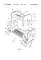
- FIG. 1is a view of one embodiment of the weightlifting system of the present invention with the weightlifting bar shown above a plurality of nested weights.
- FIG. 2is a cutaway view of the weightlifting bar of FIG. 1 .
- FIG. 3is a cross-sectional view of the grip of the weightlifting bar shown in FIG. 2 demonstrating a springloaded knob which selectively engages a pair of desired slots within the grip.
- FIG. 4is a view of the weightlifting bar of FIG. 1 having one of the weights from the weight nest shown in FIG. 1 coupled thereto.
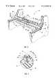
- FIG. 5is a view of yet another embodiment of a weightlifting system of the present invention comprising a handle having a weight affixed thereto.
- FIG. 6is a cross sectional, cutaway view of one example of the means for selectively attaching each end of the handle to a corresponding end of the weight when the handle is disposed between the first and second ends of the weight.
- FIG. 7is a view of the weightlifting system of FIG. 5 showing the handle of the system disposed within the weight nest of the system.
- Weightlifting system 10comprises (i) one or more weights 12 ; and (ii) a weightlifting bar 14 configured to selectively engage the one or more weights 12 .
- First weight 16 of weight nest 12has a first upstanding end 17 , a second upstanding end 18 , and a cross member 19 extending therebetween.
- Weightlifting bar 14comprises (i) a handle 20 having first and second opposing ends 22 , 24 ; and (ii) means for selectively attaching each end 22 , 24 to a corresponding end 17 , 18 of weight 16 when handle 20 is disposed between first end 17 and second end 18 of weight 16 . Weightlifting bar 14 is readily placed between first and second ends 17 , 18 of weight 16 .
- System 10enables the user to select a desired number of weights 12 to be lifted, then conveniently couple the desired weights 12 to weightlifting bar 14 .
- the userBy placing bar 14 within first weight 16 , then actuating the attaching means, the user selectively couples one or more weights 12 to bar 14 .
- the usermay couple one, two, three, four, five or even more weights 12 to bar 14 , depending upon the amount of weight desired to be lifted by the user. If certain weights are not selected by a user, they are maintained in a nested relationship with respect to each other, thereby conserving space.
- the useris able to readily release the weights from bar 14 and leave the weights in the weight nest 12 .
- System 10thus conserves space, provides for easy adjustment of weights 12 , and maintains weights on bar 14 without risk of weights 12 falling off.
- First weight 16is shown in FIG. 1 as being nested within second weight 28 .
- Second weight 28has a first end 30 , a second end 32 , and a pair of cross members 34 extending between first end 30 and second end 32 .
- a third weight 36has a first end 38 , a second end 40 and a pair of cross members 42 extending between first and second ends 38 , 40 .
- a fourth weight 44includes a first end 46 , a second end 48 , and a pair of cross members 50 extending between first and second ends 46 , 48 .
- a fifth weight 54includes first and second ends 56 , 58 and a pair of cross members 60 extending between first and second ends 56 , 58 .
- weights 16 , 28 , 36 , 44 and 54may be added in the nested relationship between weights 16 , 28 , 36 , 44 and 54 . It will also be appreciated that one, two, three or more cross members may be disposed between ends of weights.
- Each of the upstanding ends of first and second ends of weights 16 , 28 , 36 , 44 and 54is preferably comprised of a disk having an aperture 62 , 63 extending therethrough.
- the diskmay be a variety of different shapes, sizes or configurations but preferably has planar side faces 59 , 61 on opposing sides thereof in order to conveniently and efficiently enable neighboring ends of weights to mate with and be stacked next to each other and to allow weightlifting bar 14 to be disposed between first and second ends 17 , 18 of weight 16 .
- each diskhas a slot 65 in a lower portion thereof which receives each cross member corresponding to each disk and allows inner weights to nest atop cross members of neighboring weights.
- Cross members 19 , 34 , 42 , 50 and 60may be coupled to respective weights 16 , 28 , 36 , 44 , 54 in a variety of different manners such as by being integrally connected to respective first and second ends, by being welded to respective ends, by being bolted or screwed into respective ends, or in a variety of other methods as is known by those skilled in the art.
- the cross membersBy being coupled to the lower portions of the first and second upstanding ends of their respective weight, such as by being coupled to the lower surface (as shown in FIG. 1) of the upstanding ends or by being coupled to the lower inside portion of the upstanding ends, the cross members avoid interference with the wrist of the user.
- each end of each weighthas an aperture 62 , 63 extending therethrough.
- Each weightis also configured such that the apertures 62 in the first upstanding ends of each weight in the nest 12 are in axial alignment and such that the apertures 63 in the second upstanding ends of each weight in the nest 12 are in axial alignment.
- second weight 28is configured to receive first weight 16 between ends 30 , 32 such that the apertures in the ends 17 , 30 are in axial alignment and such that the apertures in ends 18 , 32 are in axial alignment.
- each aperture extending through respective first ends of weights 16 , 28 , 36 , 44 and 54has the same size and axis as neighboring apertures
- a single passageway 62is formed through each of the first ends of weights 16 , 28 , 36 , 44 and 54 .
- a single passageway 63is formed through each of the second ends of weights 16 , 28 , 36 , 44 and 54 . This alignment allows rods from bar 14 to be selectively disposed through one or more weights, as will be discussed in greater detail below.
- Handle 20 of weightlifting bar 14has (i) an exterior surface 64 ; and (ii) an interior surface 66 defining a channel 68 extending between first end 22 and second end 24 .
- weightlifting bar 14includes means for selectively attaching each end 22 , 24 of handle 20 to a corresponding end 17 , 18 of weight 16 when handle 20 is disposed between first end 17 and second end 18 of weight 16 .
- the means for selectively attaching each end 22 , 24 of handle to a corresponding end 17 , 18 of weight 16comprises (i) first and second rods 94 , 98 movably disposed within the channel 68 of handle 20 ; and (ii) means for selectively advancing the first and second rods 94 , 98 out of opposing ends of handle 20 .
- the means for selectively advancing the first and second rods 94 , 98 out of handle 20comprises a pinion gear 92 rotatably disposed within channel 68 of handle 20 .
- First rod 94has a first end 95 positioned at the first end 22 of the handle and an opposing second end having teeth 96 formed along a length thereof, teeth 96 engaging pinion gear 92 .
- Second rod 98has a first end 99 positioned at the second end 24 of handle 20 and an opposing second end having teeth 100 formed along a length thereof. Teeth 100 of second rod 98 engage pinion gear 92 on a side opposite first rod 94 .
- Pinion gear 92is pivotally coupled to interior surface 66 of handle 20 through the use of a pin (not shown) disposed through gear 92 and coupled to interior surface 66 .
- the inventionfurther comprises means for selectively advancing the first and second rods 94 , 98 in desired increments out of opposing ends 22 , 24 of handle 20 .
- Thisselectively retains rods 94 , 98 in a desired, locked position and may also permit the user to select one additional weight for each increment used, for example.
- the means for selectively advancing rods 94 , 98 in desired incrementscomprises a springloaded knob 72 coupled to first rod, or, as shown in FIGS. 1-3, second rod 98 .
- Knob 72selectively engages one of a plurality of longitudinally aligned slots 74 formed along one side of channel 68 and, preferably, one of a plurality of longitudinally aligned slots 75 formed along another side of channel 68 .
- Handle 20thus preferably includes first and second rows of longitudinally aligned slots 74 , 75 formed within the channel, each slot being separated by a tooth 76 . Only the first row 74 is featured in FIG. 2, but handle 20 includes an identical row of slots 75 on an opposing side of channel 68 .
- FIG. 3depicts knob 72 as engaging a pair of slots, 74 , 75 one from each of the rows of slots.
- Knob 72is thus preferably configured to selectively engage a pair of desired slots on opposing sides of channel 68 , thereby maintaining rods 94 , 98 in a desired orientation with respect to handle 20 until knob 72 is selectively moved from the pair of slots by a user.
- Springloaded knob 72is selectively depressed in order to move knob 72 between slots.
- knob 72includes a button 106 and first and second flanges 114 , 116 extending from button 106 and configured to selectively engage respective first and second slots 74 , 75 . Depression of button 106 enables flanges 114 , 116 to bypass teeth 76 as knob 72 is adjusted as desired by the user. Thus, if the user desires to lift additional weight, the user moves knob 72 further toward end 24 , thereby advancing rods 94 , 98 further from handle 20 into additional weights.
- channel 68includes three openings.
- Knob 72selectively moves back and forth within first opening 70 of channel 68 .
- Rod 94selectively extends through a second opening 78 , while rod 98 selectively extends through a third opening 80 in handle 20 .
- L-shaped member 108is disposed within a recess within rod 94 .
- L-shaped member 108has first and second recesses for receiving first and second springs 102 , 104 and a third recess between the first and second recesses for receiving a cylindrically shaped guide pin (not shown in FIGS. 2 and 3 ).
- Knob 72also has recesses in the lower surface 112 thereof for receiving springs 102 , 104 .
- the guide pinextends integrally from the lower surface 112 of knob 72 between springs 102 , 104 .
- the guide pininsures the smooth, aligned movement of knob 72 along a substantially perpendicular axis with respect to the longitudinal axis of handle 20 .
- Springs 102 , 104allow button 106 to be selectively depressed when desired by the user, but maintain knob 72 a nondepressed, desired orientation when knob 72 is not compressed by the user.
- Button 106includes an upper recess 118 for placement of the thumb or finger of the user therein, thereby allowing the user to more readily push button 106 to a desired orientation.
- knob 72is freely movable within cavity 68 .
- second rod 98moves within cavity 68 , causing first rod 94 to move in an opposing direction within cavity 68 .
- the outer tip 120 of rod 94extends through opening 78 and into first end 17 of weight 16 .
- outer tip 122 of rod 98is moved into second end 18 of weight 16 .
- outer tips 120 , 122 of first and second rods 94 , 98extend into weights 28 , 36 , 44 , 54 and so on as desired while weightlifting bar 14 is disposed within weight nest 12 .
- outer ends 120 , 122are selectively retracted into weightlifting bar 14 by depressing button 106 , then sliding button 106 toward the center of handle 20 , thereby retracting rods 94 , 98 and allowing the desired weights to slide off weightlifting bar 14 .
- rods 94 , 98pick up or release successive weights.
- rods 94 , 98may be advanced manually without knob 72 by pressing against one of rods 94 , 98 , for example.
- the means for selectively advancing rods 94 , 98comprises first and second rods 94 , 98 and pinion gear 92 without knob 72 .
- handle 20comprises (i) a cylindrically-shaped, hollow grip 81 ; and (ii) first and second end plates 82 , 84 coupled to opposing sides of grip 81 .
- End plates 82 , 84are preferably flat on the exterior surfaces 86 thereof, thereby providing a smooth mating surface corresponding to the ends of weights 12 .
- end plates 82 , 84are optional and that weights 12 may also be coupled to handle 20 by being coupled directly to grip 81 .
- End plates 82 , 84include a respective lower slot 88 , 90 which receives cross-members 19 , 34 , 42 , 50 and 60 .
- weightlifting bar 14can be conveniently placed in a mating relationship with weight 16 when weightlifting bar 14 is lowered onto the nest of weights 12 .
- Slots 88 , 90also assist by orienting rods 94 , 98 into respective apertures 62 , 63 when handle 20 is placed onto the cross members of weights 12 .
- weight 16may be deposited conveniently within the nest or, optionally, additional weights 28 , 36 , 44 , and/or 54 may be grasped by weightlifting bar 14 .
- ends 120 , 122 of rods 94 , 98are tapered at the tips thereof to permit smooth sliding thereof into the ends of desired weights.
- Adjustment of the weights coupled to handle 20may be accomplished using a single hand. Once handle 20 is disposed within weight 16 , the user conveniently presses knob 72 (or, optionally one of rods 94 , 98 ) with the user's thumb or finger, thereby advancing rods 94 , 98 out of handle 20 and into a desired number of weights.
- This one-handed weight adjustment capabilityhas many advantages. The user is not required to release the handle 20 in order to adjust the weight. The user may use one hand to hold handle 20 and adjust the weight thereon while another hand performs another operation. In addition, it is possible for the user to hold two different handles 20 , i.e., by holding one in each hand, and simultaneously adjust the number of weights on each handle 20 .
- the weightsmay have their respective weights stamped thereon or otherwise displayed in order to show the user the total amount of weight lifted.
- knob 72is shown in FIGS. 1-4 as extending slightly above grip 81 of handle 20 , it is possible to orient knob 72 within channel 68 such that knob 72 does not extend above grip 81 during use.
- rods 94 , 98are essentially cylindrical. In another embodiment, however, the rods are D-shaped, having a flat surface in which the teeth for coupling with a pinion gear are formed. In this alternative embodiment, there is a corresponding D shape of the holes within the ends of the weights.
- handle 151comprises a grip 152 and end plates 154 , 156 extending from grip 152 .
- End plates 154 , 156 of handle 151are each comprised of a respective first end plate portion 158 , 160 and a respective second end plate portion 162 , 164 .
- Second end plate portion 162 , 164is substantially similar to first and second ends 17 , 18 of weight 16 shown in FIG. 1 .
- first end plate portions 158 , 160extend integrally from grip 152 .
- Grip 152 and first and second end plate portions 158 , 160may be comprised of a plastic or metal material, for example.
- grip 152 and portions 158 , 160are manufactured in first and second half sections which are combined by being screwed or bolted together (the screws or bolts extending between half sections of the grip) to form a single unit.
- handle 151further includes a cross member 165 disposed between portions 162 , 164 , assisting in indexing handle 151 when handle 151 is placed within weight nest 167 .
- cross member 165is placed in the appropriate location between cross members 168 of weight 169 of nest 167 , the rods 170 , 172 of handle 151 are properly aligned 119 to be placed within respective apertures 174 , 176 of weights 167 .
- FIG. 6is a cross sectional, cutaway view of another example of means for selectively attaching each end of handle, such as handle 151 , to a corresponding end of weight, such as weight 169 when handle 151 is disposed between the first and second ends of the weight.
- first and second rods 170 , 172are aligned vertically within handle 151 , the pinion 178 being disposed between rods 170 , 172 .
- knob 180has guide pins 182 , 184 extending integrally therefrom which couple directly into respective recesses 186 , 188 within rod 170 .
- a spring 190is disposed between knob 180 and another recess 192 in rod 170 , thereby springloading knob 180 .
- Knob 180further includes a flange (not shown) which selectively engages a pair of slots 194 (see FIG. 5) within first and second longitudinal rows of slots in handle 151 (second row not shown).
- FIG. 7demonstrates weights 169 , 200 , 202 , 204 being removably coupled to handle 151 .
- each end of each weight 169 , 200 , 202 , 204 and the outer faces of end plates 154 , 156are oriented slightly at an angle outwardly with respect to an axis 206 perpendicular to the longitudinal axis of the grip 152 , thereby enabling the weights to conveniently fit within each other and receive bar 151 .
- the angleis more dramatic.
- Yet another example of the means for selectively attaching each end of the handle to a corresponding end of the weight when the handle is disposed between the first end and second end of the weightcomprises a single rod moving within the handle rather than two rods having a pinion therebetween.
- a single rodis movably disposed within the channel of the handle.
- the rodis selectively advanced out of a first end of the handle, by pressing against a springloaded knob on the rod, for example, or by pressing against the rod without a knob.
- the means for selectively advancing the rodmay comprise the rod being configured to be pressed by the user out of an aperture in the handle, for example.
- the springloaded knobmay be incrementally advanced within one or more slots in the channel as discussed above with reference to FIGS. 1-4, for example.
- the second end of the handleis configured to fit within the aperture of a one end of a weight such as weight 16 . Upon placing the second end into one end of the weight such as end 17 , then advancing the rod out of the first end of the handle into the second end 18 of the weight, both ends of the handle are selectively coupled to the weight.
- the weight lifting system of the present inventionhas many advantages over previous weightlifting systems.
- the weightlifting barmay be readily placed within a variety of different weights in order to selectively lift one or more of the weights, thereby allowing the user to select fewer or more weights as desired.
- the weightsare retained within a nested relationship in order to conserve space and the weights are readily placed onto or removed from the weightlifting bar, thereby allowing quick and efficient placement of weights onto the bar and permitting quick and efficient removal of weights therefrom.
- the weightsare weighted equally on opposing sides thereon thereby providing even weight distribution upon being lifted by a user.
- Another advantageis that both sides of a weight may be added at the same time.
- a weightmay be added to the handle merely by pushing a button in the intermediate portion of the handle once the handle has been disposed within the weight.
Landscapes
- Health & Medical Sciences (AREA)
- Life Sciences & Earth Sciences (AREA)
- Biophysics (AREA)
- Orthopedic Medicine & Surgery (AREA)
- General Health & Medical Sciences (AREA)
- Physical Education & Sports Medicine (AREA)
- Motorcycle And Bicycle Frame (AREA)
Abstract
Description
Claims (27)
Priority Applications (2)
| Application Number | Priority Date | Filing Date | Title |
|---|---|---|---|
| US09/042,755US6228003B1 (en) | 1998-03-17 | 1998-03-17 | Adjustable dumbbell and system |
| US09/247,160US6261022B1 (en) | 1998-03-17 | 1999-02-09 | Adjustable dumbbell and system |
Applications Claiming Priority (1)
| Application Number | Priority Date | Filing Date | Title |
|---|---|---|---|
| US09/042,755US6228003B1 (en) | 1998-03-17 | 1998-03-17 | Adjustable dumbbell and system |
Related Child Applications (1)
| Application Number | Title | Priority Date | Filing Date |
|---|---|---|---|
| US09/247,160Continuation-In-PartUS6261022B1 (en) | 1998-03-17 | 1999-02-09 | Adjustable dumbbell and system |
Publications (1)
| Publication Number | Publication Date |
|---|---|
| US6228003B1true US6228003B1 (en) | 2001-05-08 |
Family
ID=21923581
Family Applications (1)
| Application Number | Title | Priority Date | Filing Date |
|---|---|---|---|
| US09/042,755Expired - LifetimeUS6228003B1 (en) | 1998-03-17 | 1998-03-17 | Adjustable dumbbell and system |
Country Status (1)
| Country | Link |
|---|---|
| US (1) | US6228003B1 (en) |
Cited By (116)
| Publication number | Priority date | Publication date | Assignee | Title |
|---|---|---|---|---|
| US20020055426A1 (en)* | 1997-09-29 | 2002-05-09 | Krull Mark A. | Exercise resistance methods and apparatus |
| US20020101880A1 (en)* | 2001-01-30 | 2002-08-01 | Byoung-Jo Kim | Network service for adaptive mobile applications |
| US20020183174A1 (en)* | 2001-05-31 | 2002-12-05 | Paul Chen | Adjustable dumbbell having easily adjusting structure |
| US6500101B1 (en)* | 2000-08-07 | 2002-12-31 | James Chen | Adjustable dumbbell |
| US20030096683A1 (en)* | 2000-02-09 | 2003-05-22 | Fenelon Paul J. | Balanced stackable dumbbell system |
| US20030114276A1 (en)* | 2001-12-13 | 2003-06-19 | Schiff Jon D. | Weightlifting apparatus |
| WO2003063969A3 (en)* | 2002-01-31 | 2003-09-04 | Mark A Krull | Adjustable weight exercise methods and apparatus |
| US20030199369A1 (en)* | 2002-04-18 | 2003-10-23 | Krull Mark A. | Adjustable mass exercise methods and apparatus |
| US20030199368A1 (en)* | 2002-04-18 | 2003-10-23 | Krull Mark A. | Weight selection methods and apparatus |
| US20040005968A1 (en)* | 2002-06-07 | 2004-01-08 | Nautilus, Inc. | Adjustable dumbbell system |
| US6679816B1 (en)* | 1999-04-13 | 2004-01-20 | Mark A. Krull | Adjustable weight exercise methods and apparatus |
| US20040072661A1 (en)* | 2002-10-11 | 2004-04-15 | Krull Mark A. | Methods and apparatus for adjusting weight resistance to exercise |
| EP1447115A1 (en)* | 2003-02-14 | 2004-08-18 | Intellex Inc. | Selectorized dumbbell using commodity weights |
| US20040162196A1 (en)* | 2003-02-11 | 2004-08-19 | Degroot Karl | Fixed dumbbell |
| US20040198569A1 (en)* | 2003-04-02 | 2004-10-07 | Anthony Sanford-Schwentke | Weight adjustable dumbbell |
| USD498272S1 (en) | 2003-06-20 | 2004-11-09 | Northpole Limited | Adjustable dumbbell |
| USD500820S1 (en)* | 2003-07-29 | 2005-01-11 | Mark A. Krull | Selectorized dumbbell handle |
| US20050079961A1 (en)* | 2003-10-13 | 2005-04-14 | Dalebout William T. | Weight lifting system with internal cam mechanism |
| US6899661B1 (en)* | 1997-07-01 | 2005-05-31 | Mark A. Krull | Exercise resistance methods and apparatus |
| USD508628S1 (en) | 2002-07-31 | 2005-08-23 | Nautilus, Inc. | Adjustable dumbbell support base |
| US20050233873A1 (en)* | 2004-04-14 | 2005-10-20 | James Chen | Weight-adjustable dumbbell |
| US20060003876A1 (en)* | 2004-07-01 | 2006-01-05 | Francois Duhamel | Dumbbell with angled bar |
| US20060025287A1 (en)* | 2002-09-25 | 2006-02-02 | Chermack Darren P | Dumbell adjustable in weight |
| US6997856B1 (en)* | 2002-05-23 | 2006-02-14 | Krull Mark A | Adjustable weight exercise methods and apparatus |
| US20060105889A1 (en)* | 2004-10-04 | 2006-05-18 | Nautilus, Inc. | Exercise machine having rotatable weight selection index |
| US7087000B1 (en) | 2003-10-27 | 2006-08-08 | Morris Wayne Walker | Collarless barbell sleeve |
| USD528173S1 (en) | 2003-06-05 | 2006-09-12 | Nautilus, Inc. | Adjustable dumbbell base |
| USD528611S1 (en) | 2004-08-16 | 2006-09-19 | Nautilus, Inc. | Adjustable dumbbell |
| US20060217245A1 (en)* | 2005-03-17 | 2006-09-28 | Nautilus, Inc. | Weight selection apparatus for a weight stack |
| US7128696B1 (en)* | 2002-05-02 | 2006-10-31 | Krull Mark A | Adjustable mass exercise apparatus and methods |
| US7128697B1 (en)* | 1999-12-21 | 2006-10-31 | Krull Mark A | Exercise weight selection methods and apparatus |
| US20070004569A1 (en)* | 2005-06-30 | 2007-01-04 | Guofang Cao | Weight plates stacking system for fitness training equipment |
| USD536752S1 (en)* | 2005-02-04 | 2007-02-13 | D.K.B. Group, Llc | Weight training device |
| USD540405S1 (en) | 2002-07-31 | 2007-04-10 | Nautilus, Inc. | Adjustable dumbbell |
| USD540894S1 (en) | 2002-08-01 | 2007-04-17 | Nautilus, Inc. | Adjustable dumbbell |
| US20070161474A1 (en)* | 2006-01-09 | 2007-07-12 | Stamina Products, Inc. | Adjustable weight |
| US20070184945A1 (en)* | 2006-02-08 | 2007-08-09 | Asia Regent Limited | Adjustable dumbbell |
| US20070254785A1 (en)* | 2006-02-08 | 2007-11-01 | Asia Regent Limited | Adjustable dumbbell and method |
| WO2007123461A1 (en)* | 2006-04-26 | 2007-11-01 | Svenberg, Tomas | Dumbbell |
| US20080032873A1 (en)* | 2006-08-02 | 2008-02-07 | Towley Carl K | Selectorized dumbbell having shock absorbing system |
| US20080070761A1 (en)* | 2006-09-13 | 2008-03-20 | Stamina Products, Inc | Dumbbell |
| US20080085821A1 (en)* | 2006-10-04 | 2008-04-10 | Nautilus, Inc. | Exercise machine having rotatable weight selection index |
| US20090048079A1 (en)* | 2007-08-15 | 2009-02-19 | Mark Nalley | Dumbbell weight training device having detachable weight plates |
| US7497814B1 (en)* | 1997-09-29 | 2009-03-03 | Krull Mark A | Adjustable weight exercise dumbbell |
| US20090186748A1 (en)* | 2008-01-23 | 2009-07-23 | Nautilus, Inc. | Adjustable dumbbell with an orientation feature |
| US20090197745A1 (en)* | 2008-02-01 | 2009-08-06 | Olson Lawrence B | Freestanding Selectable Free Weight Assembly |
| US7621855B1 (en) | 2004-01-27 | 2009-11-24 | Krull Mark A | Exercise dumbbell methods and apparatus |
| US7625322B1 (en) | 2007-09-19 | 2009-12-01 | Krull Mark A | Exercise weight adjustment methods and apparatus |
| US20100304940A1 (en)* | 2007-11-29 | 2010-12-02 | Thomas Svenberg | Dumbbell |
| US20100304938A1 (en)* | 2008-02-01 | 2010-12-02 | Olson Lawrence B | Freestanding Selectable Free Weight Assembly |
| US20100304939A1 (en)* | 2007-11-29 | 2010-12-02 | Tomas Svenberg | Dumbbell |
| US20110045956A1 (en)* | 2009-07-31 | 2011-02-24 | Matthew Colledge | Weightlifting device with mechanism for disengaging weight plates |
| EP2069030A4 (en)* | 2006-08-02 | 2011-03-16 | Intellex Inc | WEIGHT SELECTION HALFER EQUIPPED WITH KEYBOARD SELECTOR WITH DISCRETE CONNECTION PIN FOR INDIVIDUAL WEIGHTS |
| US8007415B1 (en)* | 2009-05-22 | 2011-08-30 | Recreation Supply, Inc. | Adjustable dumbbell and system |
| US20120004080A1 (en)* | 2010-03-31 | 2012-01-05 | Nautilus, Inc. | Lockout mechanism for a weight stack exercise machine |
| US8206274B2 (en) | 2009-10-21 | 2012-06-26 | Personality Gym Ab | Dumbbell |
| US8529415B2 (en) | 2007-11-29 | 2013-09-10 | Tomas Svenberg | Dumbbell |
| US8568279B2 (en) | 2010-03-31 | 2013-10-29 | Nautilus, Inc. | Engagement interface for an exercise machine |
| US8771153B2 (en) | 2010-11-08 | 2014-07-08 | Icon Ip, Inc. | Exercise weight bar with rotating handle and cam selection device |
| US8876674B2 (en) | 2010-03-31 | 2014-11-04 | Nautilus, Inc. | Selectable weight stack |
| US20160089560A1 (en)* | 2014-09-30 | 2016-03-31 | Icon Health & Fitness, Inc. | Weight Selector for Multiple Dumbbells |
| US9375602B2 (en) | 2013-03-15 | 2016-06-28 | Nautilus, Inc. | Exercise dumbbells |
| EP2956218A4 (en)* | 2013-02-13 | 2016-10-26 | Vintage Gold Holdings Ltd | WEIGHT SETTING SELECTION DEVICE AND LOCKING MECHANISM |
| US9643042B2 (en) | 2012-10-26 | 2017-05-09 | Vintage Gold Holdings Limited | Freestanding selectable free weight assembly |
| CN108721831A (en)* | 2018-07-24 | 2018-11-02 | 贵港市瑞成科技有限公司 | A kind of dumbbell weight regulating device |
| US10166431B2 (en)* | 2016-01-26 | 2019-01-01 | Powerblock Holdings, Inc. | Selectorized dumbbell with a weight selector having a continuous periphery that encloses an open interior |
| US10188890B2 (en) | 2013-12-26 | 2019-01-29 | Icon Health & Fitness, Inc. | Magnetic resistance mechanism in a cable machine |
| US10252109B2 (en) | 2016-05-13 | 2019-04-09 | Icon Health & Fitness, Inc. | Weight platform treadmill |
| US10279212B2 (en) | 2013-03-14 | 2019-05-07 | Icon Health & Fitness, Inc. | Strength training apparatus with flywheel and related methods |
| US10293211B2 (en) | 2016-03-18 | 2019-05-21 | Icon Health & Fitness, Inc. | Coordinated weight selection |
| US10426989B2 (en) | 2014-06-09 | 2019-10-01 | Icon Health & Fitness, Inc. | Cable system incorporated into a treadmill |
| US10441840B2 (en) | 2016-03-18 | 2019-10-15 | Icon Health & Fitness, Inc. | Collapsible strength exercise machine |
| US10449416B2 (en) | 2015-08-26 | 2019-10-22 | Icon Health & Fitness, Inc. | Strength exercise mechanisms |
| US10561894B2 (en) | 2016-03-18 | 2020-02-18 | Icon Health & Fitness, Inc. | Treadmill with removable supports |
| US20200147440A1 (en)* | 2018-11-09 | 2020-05-14 | Carl K. Towley, III | Dumbbell handle having a dislodgement preventing interface with the weight selector of a selectorized dumbbell |
| US10661114B2 (en) | 2016-11-01 | 2020-05-26 | Icon Health & Fitness, Inc. | Body weight lift mechanism on treadmill |
| US10786706B2 (en) | 2018-07-13 | 2020-09-29 | Icon Health & Fitness, Inc. | Cycling shoe power sensors |
| DE112013007455B3 (en)* | 2012-06-05 | 2020-11-12 | Personality Gym Ab | Weight device with weight adjustment device |
| US10918905B2 (en) | 2016-10-12 | 2021-02-16 | Icon Health & Fitness, Inc. | Systems and methods for reducing runaway resistance on an exercise device |
| US10933272B2 (en) | 2018-06-22 | 2021-03-02 | Glenn Polinsky | Auto-adjustable weight device, system, and method |
| US10940360B2 (en) | 2015-08-26 | 2021-03-09 | Icon Health & Fitness, Inc. | Strength exercise mechanisms |
| US10953305B2 (en) | 2015-08-26 | 2021-03-23 | Icon Health & Fitness, Inc. | Strength exercise mechanisms |
| US11000730B2 (en) | 2018-03-16 | 2021-05-11 | Icon Health & Fitness, Inc. | Elliptical exercise machine |
| US11033777B1 (en) | 2019-02-12 | 2021-06-15 | Icon Health & Fitness, Inc. | Stationary exercise machine |
| US11058914B2 (en) | 2016-07-01 | 2021-07-13 | Icon Health & Fitness, Inc. | Cooling methods for exercise equipment |
| US11058913B2 (en) | 2017-12-22 | 2021-07-13 | Icon Health & Fitness, Inc. | Inclinable exercise machine |
| US11187285B2 (en) | 2017-12-09 | 2021-11-30 | Icon Health & Fitness, Inc. | Systems and methods for selectively rotationally fixing a pedaled drivetrain |
| US11244751B2 (en) | 2012-10-19 | 2022-02-08 | Finish Time Holdings, Llc | Method and device for providing a person with training data of an athlete as the athlete is performing a swimming workout |
| US11298577B2 (en) | 2019-02-11 | 2022-04-12 | Ifit Inc. | Cable and power rack exercise machine |
| US11326673B2 (en) | 2018-06-11 | 2022-05-10 | Ifit Inc. | Increased durability linear actuator |
| US11451108B2 (en) | 2017-08-16 | 2022-09-20 | Ifit Inc. | Systems and methods for axial impact resistance in electric motors |
| US11534654B2 (en) | 2019-01-25 | 2022-12-27 | Ifit Inc. | Systems and methods for an interactive pedaled exercise device |
| US11534651B2 (en)* | 2019-08-15 | 2022-12-27 | Ifit Inc. | Adjustable dumbbell system |
| US11673036B2 (en) | 2019-11-12 | 2023-06-13 | Ifit Inc. | Exercise storage system |
| US11700905B2 (en) | 2014-03-10 | 2023-07-18 | Ifit Inc. | Pressure sensor to quantify work |
| US11794070B2 (en) | 2019-05-23 | 2023-10-24 | Ifit Inc. | Systems and methods for cooling an exercise device |
| USD1006920S1 (en)* | 2023-08-23 | 2023-12-05 | Duoming Zhong | Dumbbell |
| US11850497B2 (en) | 2019-10-11 | 2023-12-26 | Ifit Inc. | Modular exercise device |
| US11878199B2 (en) | 2021-02-16 | 2024-01-23 | Ifit Inc. | Safety mechanism for an adjustable dumbbell |
| US11931621B2 (en) | 2020-03-18 | 2024-03-19 | Ifit Inc. | Systems and methods for treadmill drift avoidance |
| US11951377B2 (en) | 2020-03-24 | 2024-04-09 | Ifit Inc. | Leaderboard with irregularity flags in an exercise machine system |
| US12029935B2 (en) | 2021-08-19 | 2024-07-09 | Ifit Inc. | Adjustment mechanism for an adjustable kettlebell |
| US12029961B2 (en) | 2020-03-24 | 2024-07-09 | Ifit Inc. | Flagging irregularities in user performance in an exercise machine system |
| USD1048247S1 (en)* | 2024-07-30 | 2024-10-22 | Zhongjie Chen | Dumbbell |
| US12176009B2 (en) | 2021-12-30 | 2024-12-24 | Ifit Inc. | Systems and methods for synchronizing workout equipment with video files |
| US12219201B2 (en) | 2021-08-05 | 2025-02-04 | Ifit Inc. | Synchronizing video workout programs across multiple devices |
| US12233305B2 (en)* | 2022-02-21 | 2025-02-25 | Zhejiang Kangwang Industry & Trade Co., Ltd | Dumbbell convenient for adjusting load |
| USD1064131S1 (en)* | 2023-10-17 | 2025-02-25 | Jinghua Li | Dumbbell |
| USD1064129S1 (en)* | 2023-06-20 | 2025-02-25 | Guanhua ZHOU | Dumbbell |
| US12263371B2 (en) | 2021-04-27 | 2025-04-01 | Ifit Inc. | Devices, systems, and methods for rotating a tread belt in two directions |
| US12280294B2 (en) | 2021-10-15 | 2025-04-22 | Ifit Inc. | Magnetic clutch for a pedaled drivetrain |
| USD1078880S1 (en)* | 2023-08-23 | 2025-06-10 | Ven Diagnostics, LLC | Swiveling exercise weight |
| US12350573B2 (en) | 2021-04-27 | 2025-07-08 | Ifit Inc. | Systems and methods for cross-training on exercise devices |
| US12350547B2 (en) | 2022-02-28 | 2025-07-08 | Ifit Inc. | Devices, systems, and methods for moving a movable step through a transition zone |
| US12409375B2 (en) | 2022-03-18 | 2025-09-09 | Ifit Inc. | Systems and methods for haptic simulation in incline exercise devices |
| US12433815B2 (en) | 2020-10-02 | 2025-10-07 | Ifit Inc. | Massage roller with pressure sensors |
Citations (6)
| Publication number | Priority date | Publication date | Assignee | Title |
|---|---|---|---|---|
| US4529198A (en)* | 1983-10-17 | 1985-07-16 | Hettick Jr Edward K | Weight lifting apparatus |
| SU1258447A1 (en)* | 1985-03-26 | 1986-09-23 | Белорусский Ордена Трудового Красного Знамени Политехнический Институт | Apparatus for developing the leg muscle force |
| US4822035A (en)* | 1986-07-25 | 1989-04-18 | Weider Health & Fitness | Adjustable barbell bar with rotating handles |
| US5637064A (en)* | 1993-02-05 | 1997-06-10 | Intellbell Ventures | Adjustable dumbbell |
| US5769762A (en)* | 1996-07-03 | 1998-06-23 | Intellbell, Inc. | Exercise weight system |
| US5779604A (en)* | 1993-02-05 | 1998-07-14 | Intellbell Ventures | Adjustable dumbbell |
- 1998
- 1998-03-17USUS09/042,755patent/US6228003B1/ennot_activeExpired - Lifetime
Patent Citations (6)
| Publication number | Priority date | Publication date | Assignee | Title |
|---|---|---|---|---|
| US4529198A (en)* | 1983-10-17 | 1985-07-16 | Hettick Jr Edward K | Weight lifting apparatus |
| SU1258447A1 (en)* | 1985-03-26 | 1986-09-23 | Белорусский Ордена Трудового Красного Знамени Политехнический Институт | Apparatus for developing the leg muscle force |
| US4822035A (en)* | 1986-07-25 | 1989-04-18 | Weider Health & Fitness | Adjustable barbell bar with rotating handles |
| US5637064A (en)* | 1993-02-05 | 1997-06-10 | Intellbell Ventures | Adjustable dumbbell |
| US5779604A (en)* | 1993-02-05 | 1998-07-14 | Intellbell Ventures | Adjustable dumbbell |
| US5769762A (en)* | 1996-07-03 | 1998-06-23 | Intellbell, Inc. | Exercise weight system |
Non-Patent Citations (1)
| Title |
|---|
| PowerBlock, The Worlds' Only Selectorized Dumbbell, 1995 IntellBell, Inc.* |
Cited By (212)
| Publication number | Priority date | Publication date | Assignee | Title |
|---|---|---|---|---|
| US6899661B1 (en)* | 1997-07-01 | 2005-05-31 | Mark A. Krull | Exercise resistance methods and apparatus |
| US7497814B1 (en)* | 1997-09-29 | 2009-03-03 | Krull Mark A | Adjustable weight exercise dumbbell |
| US20020055426A1 (en)* | 1997-09-29 | 2002-05-09 | Krull Mark A. | Exercise resistance methods and apparatus |
| US6733424B2 (en)* | 1997-09-29 | 2004-05-11 | Mark A. Krull | Exercise resistance methods and apparatus |
| US6679816B1 (en)* | 1999-04-13 | 2004-01-20 | Mark A. Krull | Adjustable weight exercise methods and apparatus |
| US7128697B1 (en)* | 1999-12-21 | 2006-10-31 | Krull Mark A | Exercise weight selection methods and apparatus |
| US20030096683A1 (en)* | 2000-02-09 | 2003-05-22 | Fenelon Paul J. | Balanced stackable dumbbell system |
| US7491155B2 (en)* | 2000-02-09 | 2009-02-17 | Fenelon Paul J | Balanced stackable dumbbell system |
| US6500101B1 (en)* | 2000-08-07 | 2002-12-31 | James Chen | Adjustable dumbbell |
| US20020101880A1 (en)* | 2001-01-30 | 2002-08-01 | Byoung-Jo Kim | Network service for adaptive mobile applications |
| US20020183174A1 (en)* | 2001-05-31 | 2002-12-05 | Paul Chen | Adjustable dumbbell having easily adjusting structure |
| US6656093B2 (en)* | 2001-05-31 | 2003-12-02 | Paul Chen | Adjustable dumbbell having easily adjusting structure |
| US20030114276A1 (en)* | 2001-12-13 | 2003-06-19 | Schiff Jon D. | Weightlifting apparatus |
| WO2003063969A3 (en)* | 2002-01-31 | 2003-09-04 | Mark A Krull | Adjustable weight exercise methods and apparatus |
| US7077790B1 (en) | 2002-01-31 | 2006-07-18 | Krull Mark A | Adjustable weight exercise methods and apparatus |
| AU2003205292B2 (en)* | 2002-01-31 | 2008-06-19 | Krull, Mark A | Adjustable weight exercise methods and apparatus |
| US20030199368A1 (en)* | 2002-04-18 | 2003-10-23 | Krull Mark A. | Weight selection methods and apparatus |
| US7534199B2 (en)* | 2002-04-18 | 2009-05-19 | Nautilus, Inc. | Weight selection methods and apparatus |
| US20060223684A1 (en)* | 2002-04-18 | 2006-10-05 | Nautilus, Inc. | Weight selection methods and apparatus |
| US20030199369A1 (en)* | 2002-04-18 | 2003-10-23 | Krull Mark A. | Adjustable mass exercise methods and apparatus |
| US6855097B2 (en)* | 2002-04-18 | 2005-02-15 | Mark A. Krull | Adjustable mass exercise methods and apparatus |
| US7077791B2 (en)* | 2002-04-18 | 2006-07-18 | Mautilus, Inc. | Weight selection methods and apparatus |
| US7128696B1 (en)* | 2002-05-02 | 2006-10-31 | Krull Mark A | Adjustable mass exercise apparatus and methods |
| US6997856B1 (en)* | 2002-05-23 | 2006-02-14 | Krull Mark A | Adjustable weight exercise methods and apparatus |
| US20110003668A1 (en)* | 2002-06-07 | 2011-01-06 | Nautilus, Inc. | Adjustable dumbbell system |
| US20080039299A1 (en)* | 2002-06-07 | 2008-02-14 | Nautilus, Inc. | Adjustable dumbbell system |
| US8002680B2 (en) | 2002-06-07 | 2011-08-23 | Nautilus, Inc. | Adjustable dumbbell system |
| US7794373B2 (en) | 2002-06-07 | 2010-09-14 | Nautilus, Inc. | Adjustable dumbbell system |
| US20040005968A1 (en)* | 2002-06-07 | 2004-01-08 | Nautilus, Inc. | Adjustable dumbbell system |
| US20060211550A1 (en)* | 2002-06-07 | 2006-09-21 | Nautilus, Inc. | Adjustable dumbbell system |
| US7553265B2 (en) | 2002-06-07 | 2009-06-30 | Nautilus, Inc. | Adjustable dumbbell system |
| US7261678B2 (en) | 2002-06-07 | 2007-08-28 | Nautilus, Inc. | Adjustable dumbbell system |
| US20100035736A1 (en)* | 2002-06-07 | 2010-02-11 | Nautilus, Inc. | Adjustable dumbbell system |
| US7614982B2 (en) | 2002-06-07 | 2009-11-10 | Nautilus, Inc. | Adjustable dumbbell system |
| USD540405S1 (en) | 2002-07-31 | 2007-04-10 | Nautilus, Inc. | Adjustable dumbbell |
| USD508628S1 (en) | 2002-07-31 | 2005-08-23 | Nautilus, Inc. | Adjustable dumbbell support base |
| USD540894S1 (en) | 2002-08-01 | 2007-04-17 | Nautilus, Inc. | Adjustable dumbbell |
| US20060025287A1 (en)* | 2002-09-25 | 2006-02-02 | Chermack Darren P | Dumbell adjustable in weight |
| US7090625B2 (en) | 2002-09-25 | 2006-08-15 | Darren Patrick Chermack | Dumbbell adjustable in weight |
| US20040072661A1 (en)* | 2002-10-11 | 2004-04-15 | Krull Mark A. | Methods and apparatus for adjusting weight resistance to exercise |
| US7066867B2 (en)* | 2002-10-11 | 2006-06-27 | Krull Mark A | Methods and apparatus for adjusting weight resistance to exercise |
| US20040162196A1 (en)* | 2003-02-11 | 2004-08-19 | Degroot Karl | Fixed dumbbell |
| EP1447115A1 (en)* | 2003-02-14 | 2004-08-18 | Intellex Inc. | Selectorized dumbbell using commodity weights |
| US7153244B2 (en) | 2003-02-14 | 2006-12-26 | Intellex, Inc. | Selectorized dumbbell using commodity weights |
| US7387596B2 (en)* | 2003-02-14 | 2008-06-17 | Intellex, Inc. | Selectorized dumbbell using commodity weights |
| US20090163335A1 (en)* | 2003-02-14 | 2009-06-25 | Towley Iii Carl K | Selectorized dumbbell using commodity weights |
| US20040162198A1 (en)* | 2003-02-14 | 2004-08-19 | Towley Carl K. | Selectorized dumbbell using commodity weights |
| US20070117692A1 (en)* | 2003-02-14 | 2007-05-24 | Towley Carl K Iii | Selectorized dumbbell using commodity weights |
| US7722511B2 (en)* | 2003-02-14 | 2010-05-25 | Powerblock Holdings, Inc. | Selectorized dumbbell using commodity weights |
| US8157711B2 (en)* | 2003-02-14 | 2012-04-17 | Power Block Holdings, Inc. | Selectorized dumbbell using commodity weights |
| US20040198569A1 (en)* | 2003-04-02 | 2004-10-07 | Anthony Sanford-Schwentke | Weight adjustable dumbbell |
| USD528173S1 (en) | 2003-06-05 | 2006-09-12 | Nautilus, Inc. | Adjustable dumbbell base |
| USD498272S1 (en) | 2003-06-20 | 2004-11-09 | Northpole Limited | Adjustable dumbbell |
| USD500820S1 (en)* | 2003-07-29 | 2005-01-11 | Mark A. Krull | Selectorized dumbbell handle |
| US20050079961A1 (en)* | 2003-10-13 | 2005-04-14 | Dalebout William T. | Weight lifting system with internal cam mechanism |
| US7025713B2 (en) | 2003-10-13 | 2006-04-11 | Icon Ip, Inc. | Weight lifting system with internal cam mechanism |
| US7087000B1 (en) | 2003-10-27 | 2006-08-08 | Morris Wayne Walker | Collarless barbell sleeve |
| US7621855B1 (en) | 2004-01-27 | 2009-11-24 | Krull Mark A | Exercise dumbbell methods and apparatus |
| US20050233873A1 (en)* | 2004-04-14 | 2005-10-20 | James Chen | Weight-adjustable dumbbell |
| US7381167B2 (en)* | 2004-07-01 | 2008-06-03 | Duhamel Francois | Dumbbell with angled bar |
| US20060003876A1 (en)* | 2004-07-01 | 2006-01-05 | Francois Duhamel | Dumbbell with angled bar |
| USD528611S1 (en) | 2004-08-16 | 2006-09-19 | Nautilus, Inc. | Adjustable dumbbell |
| US7740568B2 (en) | 2004-10-04 | 2010-06-22 | Nautilus, Inc. | Exercise machine having rotatable weight selection index |
| US7662074B2 (en) | 2004-10-04 | 2010-02-16 | Nautilus, Inc. | Exercise machine having rotatable weight selection index |
| US20060105889A1 (en)* | 2004-10-04 | 2006-05-18 | Nautilus, Inc. | Exercise machine having rotatable weight selection index |
| US8016729B2 (en) | 2004-10-04 | 2011-09-13 | Nautilus, Inc. | Exercise machine having rotatable weight selection index |
| US20100311550A1 (en)* | 2004-10-04 | 2010-12-09 | Nautilus, Inc. | Exercise machine having rotatable weight selection index |
| USD536752S1 (en)* | 2005-02-04 | 2007-02-13 | D.K.B. Group, Llc | Weight training device |
| US20060217245A1 (en)* | 2005-03-17 | 2006-09-28 | Nautilus, Inc. | Weight selection apparatus for a weight stack |
| US7758478B2 (en) | 2005-03-17 | 2010-07-20 | Nautilus, Inc. | Weight selection apparatus for a weight stack |
| US20070004569A1 (en)* | 2005-06-30 | 2007-01-04 | Guofang Cao | Weight plates stacking system for fitness training equipment |
| US20070161474A1 (en)* | 2006-01-09 | 2007-07-12 | Stamina Products, Inc. | Adjustable weight |
| US7578772B2 (en) | 2006-01-09 | 2009-08-25 | Stamina Products, Inc. | Adjustable weight |
| US7604577B2 (en)* | 2006-02-08 | 2009-10-20 | Asia Regent Limited | Adjustable dumbbell and method |
| US7413533B2 (en) | 2006-02-08 | 2008-08-19 | Asai Regent Limited | Adjustable dumbbell |
| US20070254785A1 (en)* | 2006-02-08 | 2007-11-01 | Asia Regent Limited | Adjustable dumbbell and method |
| US20070184945A1 (en)* | 2006-02-08 | 2007-08-09 | Asia Regent Limited | Adjustable dumbbell |
| GB2452433A (en)* | 2006-04-26 | 2009-03-04 | Tomas Svenberg | Dumbbell |
| GB2452433B (en)* | 2006-04-26 | 2010-10-06 | Tomas Svenberg | Dumbbell |
| WO2007123461A1 (en)* | 2006-04-26 | 2007-11-01 | Svenberg, Tomas | Dumbbell |
| US20090305852A1 (en)* | 2006-04-26 | 2009-12-10 | Tomas Svenberg | Dumbbell |
| US7771330B2 (en) | 2006-08-02 | 2010-08-10 | Power Block Holdings, Inc. | Selectorized dumbbell having shock absorbing system |
| EP2069030A4 (en)* | 2006-08-02 | 2011-03-16 | Intellex Inc | WEIGHT SELECTION HALFER EQUIPPED WITH KEYBOARD SELECTOR WITH DISCRETE CONNECTION PIN FOR INDIVIDUAL WEIGHTS |
| US7850581B2 (en) | 2006-08-02 | 2010-12-14 | Powerblock Holdings, Inc. | Selectorized dumbbell having shock absorbing nested weights and a shock absorbing selector |
| US20080032873A1 (en)* | 2006-08-02 | 2008-02-07 | Towley Carl K | Selectorized dumbbell having shock absorbing system |
| US20100255961A1 (en)* | 2006-08-02 | 2010-10-07 | Towley Iii Carl K | Selectorized dumbbell having shock absorbing nested weights and a shock absorbing selector |
| US20100255962A1 (en)* | 2006-08-02 | 2010-10-07 | Towley Iii Carl K | Selectorized dumbbell having a selector comprising a pin with flexible connecting prong(s) |
| US7857735B2 (en) | 2006-08-02 | 2010-12-28 | Power Block Holdings, Inc. | Selectorized dumbbell having a selector comprising a pin with flexible connecting prong(s) |
| US7429235B2 (en)* | 2006-09-13 | 2008-09-30 | Stamina Products, Inc. | Dumbbell |
| US20080070761A1 (en)* | 2006-09-13 | 2008-03-20 | Stamina Products, Inc | Dumbbell |
| US20080085821A1 (en)* | 2006-10-04 | 2008-04-10 | Nautilus, Inc. | Exercise machine having rotatable weight selection index |
| US7736283B2 (en) | 2006-10-04 | 2010-06-15 | Nautilus, Inc. | Exercise machine having rotatable weight selection index |
| US7588520B2 (en)* | 2007-08-15 | 2009-09-15 | Mark Nalley | Dumbbell weight training device having detachable weight plates |
| US20090048079A1 (en)* | 2007-08-15 | 2009-02-19 | Mark Nalley | Dumbbell weight training device having detachable weight plates |
| US7625322B1 (en) | 2007-09-19 | 2009-12-01 | Krull Mark A | Exercise weight adjustment methods and apparatus |
| US12208301B2 (en)* | 2007-11-29 | 2025-01-28 | Personality Gym Ab | Dumbbell |
| US20140206510A1 (en)* | 2007-11-29 | 2014-07-24 | Tomas Svenberg | Dumbbell |
| US9669252B2 (en)* | 2007-11-29 | 2017-06-06 | Tomas Svenberg | Dumbbell |
| US8715143B2 (en) | 2007-11-29 | 2014-05-06 | Tomas Svenberg | Dumbbell |
| US20100304939A1 (en)* | 2007-11-29 | 2010-12-02 | Tomas Svenberg | Dumbbell |
| US20210402243A1 (en)* | 2007-11-29 | 2021-12-30 | Personality Gym Ab | Dumbbell |
| US20240108937A1 (en)* | 2007-11-29 | 2024-04-04 | Personality Gym Ab | Dumbbell |
| US8529415B2 (en) | 2007-11-29 | 2013-09-10 | Tomas Svenberg | Dumbbell |
| US20100304940A1 (en)* | 2007-11-29 | 2010-12-02 | Thomas Svenberg | Dumbbell |
| US11872435B2 (en)* | 2007-11-29 | 2024-01-16 | Personality Gym Ab | Dumbbell |
| US20090186748A1 (en)* | 2008-01-23 | 2009-07-23 | Nautilus, Inc. | Adjustable dumbbell with an orientation feature |
| US7862487B2 (en)* | 2008-02-01 | 2011-01-04 | Olson Lawrence B | Freestanding selectable free weight assembly |
| US20100304938A1 (en)* | 2008-02-01 | 2010-12-02 | Olson Lawrence B | Freestanding Selectable Free Weight Assembly |
| US20090197745A1 (en)* | 2008-02-01 | 2009-08-06 | Olson Lawrence B | Freestanding Selectable Free Weight Assembly |
| US8007415B1 (en)* | 2009-05-22 | 2011-08-30 | Recreation Supply, Inc. | Adjustable dumbbell and system |
| US8298125B2 (en) | 2009-07-31 | 2012-10-30 | Icon Health & Fitness, Inc. | Weightlifting device with mechanism for disengaging weight plates |
| US20110045956A1 (en)* | 2009-07-31 | 2011-02-24 | Matthew Colledge | Weightlifting device with mechanism for disengaging weight plates |
| US8206274B2 (en) | 2009-10-21 | 2012-06-26 | Personality Gym Ab | Dumbbell |
| US20120004080A1 (en)* | 2010-03-31 | 2012-01-05 | Nautilus, Inc. | Lockout mechanism for a weight stack exercise machine |
| US8568279B2 (en) | 2010-03-31 | 2013-10-29 | Nautilus, Inc. | Engagement interface for an exercise machine |
| US8845498B2 (en)* | 2010-03-31 | 2014-09-30 | Nautilus, Inc. | Lockout mechanism for a weight stack exercise machine |
| US8876674B2 (en) | 2010-03-31 | 2014-11-04 | Nautilus, Inc. | Selectable weight stack |
| US8771153B2 (en) | 2010-11-08 | 2014-07-08 | Icon Ip, Inc. | Exercise weight bar with rotating handle and cam selection device |
| DE112013007455B3 (en)* | 2012-06-05 | 2020-11-12 | Personality Gym Ab | Weight device with weight adjustment device |
| US11244751B2 (en) | 2012-10-19 | 2022-02-08 | Finish Time Holdings, Llc | Method and device for providing a person with training data of an athlete as the athlete is performing a swimming workout |
| US12340891B2 (en) | 2012-10-19 | 2025-06-24 | Finish Time Network LLC | System and method for providing a trainer with live training data of an individual as the individual is performing a training workout |
| US11923066B2 (en) | 2012-10-19 | 2024-03-05 | Finish Time Holdings, Llc | System and method for providing a trainer with live training data of an individual as the individual is performing a training workout |
| US11322240B2 (en) | 2012-10-19 | 2022-05-03 | Finish Time Holdings, Llc | Method and device for providing a person with training data of an athlete as the athlete is performing a running workout |
| US11810656B2 (en) | 2012-10-19 | 2023-11-07 | Finish Time Holdings, Llc | System for providing a coach with live training data of an athlete as the athlete is training |
| US9643042B2 (en) | 2012-10-26 | 2017-05-09 | Vintage Gold Holdings Limited | Freestanding selectable free weight assembly |
| USRE49161E1 (en) | 2013-02-13 | 2022-08-09 | Vintage Gold Holdings Limited | Weight set selector and locking mechanism |
| US10166427B2 (en) | 2013-02-13 | 2019-01-01 | Vintage Gold Holdings Limited | Weight set selector and locking mechanism |
| EP2956218A4 (en)* | 2013-02-13 | 2016-10-26 | Vintage Gold Holdings Ltd | WEIGHT SETTING SELECTION DEVICE AND LOCKING MECHANISM |
| US10279212B2 (en) | 2013-03-14 | 2019-05-07 | Icon Health & Fitness, Inc. | Strength training apparatus with flywheel and related methods |
| US11878206B2 (en) | 2013-03-14 | 2024-01-23 | Ifit Inc. | Strength training apparatus |
| US11338169B2 (en) | 2013-03-14 | 2022-05-24 | IFIT, Inc. | Strength training apparatus |
| US10953268B1 (en) | 2013-03-14 | 2021-03-23 | Icon Health & Fitness, Inc. | Strength training apparatus |
| US10709925B2 (en) | 2013-03-14 | 2020-07-14 | Icon Health & Fitness, Inc. | Strength training apparatus |
| US9604092B2 (en) | 2013-03-15 | 2017-03-28 | Nautilus, Inc. | Exercise dumbbells |
| US9375602B2 (en) | 2013-03-15 | 2016-06-28 | Nautilus, Inc. | Exercise dumbbells |
| US10758767B2 (en) | 2013-12-26 | 2020-09-01 | Icon Health & Fitness, Inc. | Resistance mechanism in a cable exercise machine |
| US10188890B2 (en) | 2013-12-26 | 2019-01-29 | Icon Health & Fitness, Inc. | Magnetic resistance mechanism in a cable machine |
| US10967214B1 (en) | 2013-12-26 | 2021-04-06 | Icon Health & Fitness, Inc. | Cable exercise machine |
| US11700905B2 (en) | 2014-03-10 | 2023-07-18 | Ifit Inc. | Pressure sensor to quantify work |
| US10426989B2 (en) | 2014-06-09 | 2019-10-01 | Icon Health & Fitness, Inc. | Cable system incorporated into a treadmill |
| US20160089560A1 (en)* | 2014-09-30 | 2016-03-31 | Icon Health & Fitness, Inc. | Weight Selector for Multiple Dumbbells |
| US9795822B2 (en)* | 2014-09-30 | 2017-10-24 | Icon Health & Fitness, Inc. | Weight selector for multiple dumbbells |
| US10449416B2 (en) | 2015-08-26 | 2019-10-22 | Icon Health & Fitness, Inc. | Strength exercise mechanisms |
| US10940360B2 (en) | 2015-08-26 | 2021-03-09 | Icon Health & Fitness, Inc. | Strength exercise mechanisms |
| US10953305B2 (en) | 2015-08-26 | 2021-03-23 | Icon Health & Fitness, Inc. | Strength exercise mechanisms |
| US10864403B2 (en)* | 2016-01-26 | 2020-12-15 | Powerblock Holdings, Inc. | Selectorized dumbbell with a weight selector having a continuous periphery that encloses an open interior |
| US10166431B2 (en)* | 2016-01-26 | 2019-01-01 | Powerblock Holdings, Inc. | Selectorized dumbbell with a weight selector having a continuous periphery that encloses an open interior |
| US20190192896A1 (en)* | 2016-01-26 | 2019-06-27 | Powerblock Holdings, Inc. | Selectorized dumbbell with a weight selector having a continuous periphery that encloses an open interior |
| US12029943B2 (en) | 2016-03-18 | 2024-07-09 | Ifit Inc. | Stationary exercise machine configured to execute a programmed workout with aerobic portions and lifting portions |
| US10441840B2 (en) | 2016-03-18 | 2019-10-15 | Icon Health & Fitness, Inc. | Collapsible strength exercise machine |
| US12029944B2 (en) | 2016-03-18 | 2024-07-09 | Ifit Inc. | Stationary exercise machine configured to execute a programmed workout with aerobic portions and lifting portions |
| US11794075B2 (en) | 2016-03-18 | 2023-10-24 | Ifit Inc. | Stationary exercise machine configured to execute a programmed workout with aerobic portions and lifting portions |
| US11013960B2 (en) | 2016-03-18 | 2021-05-25 | Icon Health & Fitness, Inc. | Exercise system including a stationary bicycle and a free weight cradle |
| US10293211B2 (en) | 2016-03-18 | 2019-05-21 | Icon Health & Fitness, Inc. | Coordinated weight selection |
| US12023549B2 (en) | 2016-03-18 | 2024-07-02 | Ifit Inc. | Stationary exercise machine configured to execute a programmed workout with aerobic portions and lifting portions |
| US10561894B2 (en) | 2016-03-18 | 2020-02-18 | Icon Health & Fitness, Inc. | Treadmill with removable supports |
| US11565148B2 (en) | 2016-03-18 | 2023-01-31 | Ifit Inc. | Treadmill with a scale mechanism in a motor cover |
| US10864407B2 (en) | 2016-03-18 | 2020-12-15 | Icon Health & Fitness, Inc. | Coordinated weight selection |
| US10252109B2 (en) | 2016-05-13 | 2019-04-09 | Icon Health & Fitness, Inc. | Weight platform treadmill |
| US11779812B2 (en) | 2016-05-13 | 2023-10-10 | Ifit Inc. | Treadmill configured to automatically determine user exercise movement |
| US10994173B2 (en) | 2016-05-13 | 2021-05-04 | Icon Health & Fitness, Inc. | Weight platform treadmill |
| US11058914B2 (en) | 2016-07-01 | 2021-07-13 | Icon Health & Fitness, Inc. | Cooling methods for exercise equipment |
| US10918905B2 (en) | 2016-10-12 | 2021-02-16 | Icon Health & Fitness, Inc. | Systems and methods for reducing runaway resistance on an exercise device |
| US10661114B2 (en) | 2016-11-01 | 2020-05-26 | Icon Health & Fitness, Inc. | Body weight lift mechanism on treadmill |
| US11451108B2 (en) | 2017-08-16 | 2022-09-20 | Ifit Inc. | Systems and methods for axial impact resistance in electric motors |
| US11187285B2 (en) | 2017-12-09 | 2021-11-30 | Icon Health & Fitness, Inc. | Systems and methods for selectively rotationally fixing a pedaled drivetrain |
| US12270441B2 (en) | 2017-12-09 | 2025-04-08 | Ifit Inc. | Systems and methods for selectively rotationally fixing a pedaled drivetrain |
| US11708874B2 (en) | 2017-12-09 | 2023-07-25 | Ifit Inc. | Systems and methods for selectively rotationally fixing a pedaled drivetrain |
| US11680611B2 (en) | 2017-12-09 | 2023-06-20 | Ifit Inc. | Systems and methods for selectively rotationally fixing a pedaled drivetrain |
| US11058913B2 (en) | 2017-12-22 | 2021-07-13 | Icon Health & Fitness, Inc. | Inclinable exercise machine |
| US11000730B2 (en) | 2018-03-16 | 2021-05-11 | Icon Health & Fitness, Inc. | Elliptical exercise machine |
| US11596830B2 (en) | 2018-03-16 | 2023-03-07 | Ifit Inc. | Elliptical exercise machine |
| US11326673B2 (en) | 2018-06-11 | 2022-05-10 | Ifit Inc. | Increased durability linear actuator |
| US10933272B2 (en) | 2018-06-22 | 2021-03-02 | Glenn Polinsky | Auto-adjustable weight device, system, and method |
| US12005315B2 (en) | 2018-07-13 | 2024-06-11 | Ifit Inc. | Cycling shoe power sensors |
| US10786706B2 (en) | 2018-07-13 | 2020-09-29 | Icon Health & Fitness, Inc. | Cycling shoe power sensors |
| CN108721831A (en)* | 2018-07-24 | 2018-11-02 | 贵港市瑞成科技有限公司 | A kind of dumbbell weight regulating device |
| US10953264B2 (en)* | 2018-11-09 | 2021-03-23 | Powerblock Holdings, Inc. | Dumbbell handle having a dislodgement preventing interface with the weight selector of a selectorized dumbbell |
| US20200147440A1 (en)* | 2018-11-09 | 2020-05-14 | Carl K. Towley, III | Dumbbell handle having a dislodgement preventing interface with the weight selector of a selectorized dumbbell |
| US11534654B2 (en) | 2019-01-25 | 2022-12-27 | Ifit Inc. | Systems and methods for an interactive pedaled exercise device |
| US11452903B2 (en) | 2019-02-11 | 2022-09-27 | Ifit Inc. | Exercise machine |
| US11298577B2 (en) | 2019-02-11 | 2022-04-12 | Ifit Inc. | Cable and power rack exercise machine |
| US11642564B2 (en) | 2019-02-11 | 2023-05-09 | Ifit Inc. | Exercise machine |
| US11426633B2 (en) | 2019-02-12 | 2022-08-30 | Ifit Inc. | Controlling an exercise machine using a video workout program |
| US11058918B1 (en) | 2019-02-12 | 2021-07-13 | Icon Health & Fitness, Inc. | Producing a workout video to control a stationary exercise machine |
| US11033777B1 (en) | 2019-02-12 | 2021-06-15 | Icon Health & Fitness, Inc. | Stationary exercise machine |
| US11951358B2 (en) | 2019-02-12 | 2024-04-09 | Ifit Inc. | Encoding exercise machine control commands in subtitle streams |
| US11794070B2 (en) | 2019-05-23 | 2023-10-24 | Ifit Inc. | Systems and methods for cooling an exercise device |
| US11534651B2 (en)* | 2019-08-15 | 2022-12-27 | Ifit Inc. | Adjustable dumbbell system |
| US11850497B2 (en) | 2019-10-11 | 2023-12-26 | Ifit Inc. | Modular exercise device |
| US12296247B2 (en) | 2019-10-11 | 2025-05-13 | Ifit Inc. | Modular exercise device |
| US11673036B2 (en) | 2019-11-12 | 2023-06-13 | Ifit Inc. | Exercise storage system |
| US11931621B2 (en) | 2020-03-18 | 2024-03-19 | Ifit Inc. | Systems and methods for treadmill drift avoidance |
| US11951377B2 (en) | 2020-03-24 | 2024-04-09 | Ifit Inc. | Leaderboard with irregularity flags in an exercise machine system |
| US12029961B2 (en) | 2020-03-24 | 2024-07-09 | Ifit Inc. | Flagging irregularities in user performance in an exercise machine system |
| US12433815B2 (en) | 2020-10-02 | 2025-10-07 | Ifit Inc. | Massage roller with pressure sensors |
| US11878199B2 (en) | 2021-02-16 | 2024-01-23 | Ifit Inc. | Safety mechanism for an adjustable dumbbell |
| US12239872B2 (en) | 2021-02-16 | 2025-03-04 | Ifit Inc. | Safety mechanism for an adjustable dumbbell |
| US12350573B2 (en) | 2021-04-27 | 2025-07-08 | Ifit Inc. | Systems and methods for cross-training on exercise devices |
| US12263371B2 (en) | 2021-04-27 | 2025-04-01 | Ifit Inc. | Devices, systems, and methods for rotating a tread belt in two directions |
| US12219201B2 (en) | 2021-08-05 | 2025-02-04 | Ifit Inc. | Synchronizing video workout programs across multiple devices |
| US12029935B2 (en) | 2021-08-19 | 2024-07-09 | Ifit Inc. | Adjustment mechanism for an adjustable kettlebell |
| US12280294B2 (en) | 2021-10-15 | 2025-04-22 | Ifit Inc. | Magnetic clutch for a pedaled drivetrain |
| US12176009B2 (en) | 2021-12-30 | 2024-12-24 | Ifit Inc. | Systems and methods for synchronizing workout equipment with video files |
| US12233305B2 (en)* | 2022-02-21 | 2025-02-25 | Zhejiang Kangwang Industry & Trade Co., Ltd | Dumbbell convenient for adjusting load |
| US12350547B2 (en) | 2022-02-28 | 2025-07-08 | Ifit Inc. | Devices, systems, and methods for moving a movable step through a transition zone |
| US12409375B2 (en) | 2022-03-18 | 2025-09-09 | Ifit Inc. | Systems and methods for haptic simulation in incline exercise devices |
| USD1064129S1 (en)* | 2023-06-20 | 2025-02-25 | Guanhua ZHOU | Dumbbell |
| USD1006920S1 (en)* | 2023-08-23 | 2023-12-05 | Duoming Zhong | Dumbbell |
| USD1078880S1 (en)* | 2023-08-23 | 2025-06-10 | Ven Diagnostics, LLC | Swiveling exercise weight |
| USD1064131S1 (en)* | 2023-10-17 | 2025-02-25 | Jinghua Li | Dumbbell |
| USD1048247S1 (en)* | 2024-07-30 | 2024-10-22 | Zhongjie Chen | Dumbbell |
Similar Documents
| Publication | Publication Date | Title |
|---|---|---|
| US6228003B1 (en) | Adjustable dumbbell and system | |
| US6261022B1 (en) | Adjustable dumbbell and system | |
| US7025713B2 (en) | Weight lifting system with internal cam mechanism | |
| US12011634B2 (en) | Adjustable barbell system | |
| US7588520B2 (en) | Dumbbell weight training device having detachable weight plates | |
| US20060025287A1 (en) | Dumbell adjustable in weight | |
| US7121988B2 (en) | Weight-training apparatus having selectable weight plates | |
| US11324989B2 (en) | Weight-adjustable free-weight exercise device | |
| US6328680B1 (en) | Abdominal exercise wheel | |
| US5257964A (en) | Barbell for use in weight training | |
| US6991590B2 (en) | Ergonomic handgrip for weight lifting plates | |
| DE69516405T2 (en) | EXERCISE DEVICE | |
| US5779604A (en) | Adjustable dumbbell | |
| US5421797A (en) | Combination weight plate and dumbbell and bar for use with the same | |
| US6682464B2 (en) | Adjustable dumbbell/barbell | |
| US20020022557A1 (en) | Weightlifting plate | |
| US5230684A (en) | Triceps pyramid exerciser | |
| US20120172182A1 (en) | Multi-grip dumbbell | |
| US11045683B2 (en) | Weight lifting apparatus and system | |
| US20240181287A1 (en) | Pinion lock for adjustable barbell system | |
| GB2468857A (en) | Weight adjustable exercise device | |
| EP2961493B1 (en) | Exercise aid | |
| US12246218B2 (en) | Grip exercise assembly | |
| WO2022187535A1 (en) | Handheld weight exercise system | |
| CA3171725C (en) | Barbell system and method of use thereof |
Legal Events
| Date | Code | Title | Description |
|---|---|---|---|
| AS | Assignment | Owner name:ICON HEALTH & FITNESS, INC., UTAH Free format text:ASSIGNMENT OF ASSIGNORS INTEREST;ASSIGNORS:HALD, PATRICK J.;DALEBOUT, WILLIAM T.;MILLER, F. TROY;REEL/FRAME:009265/0436;SIGNING DATES FROM 19980415 TO 19980423 | |
| STCF | Information on status: patent grant | Free format text:PATENTED CASE | |
| AS | Assignment | Owner name:GENERAL ELECTRIC CAPITAL CORPORATION, ILLINOIS Free format text:ASSIGNMENT OF ASSIGNORS INTEREST;ASSIGNOR:ICON IP, INC.;REEL/FRAME:012036/0191 Effective date:20010629 Owner name:GENERAL ELECTRIC CAPITAL CORPORATION, ILLINOIS Free format text:SECURITY AGREEMENT;ASSIGNOR:ICON IP, INC.;REEL/FRAME:012036/0191 Effective date:20010629 | |
| AS | Assignment | Owner name:ICON IP, INC., UTAH Free format text:ASSIGNMENT OF ASSIGNORS INTEREST;ASSIGNOR:ICON HEALTH & FITNESS, INC.;REEL/FRAME:012365/0100 Effective date:20010629 | |
| AS | Assignment | Owner name:GENERAL ELECTRIC CAPITAL CORPORATION, AS AGENT, CONNECTICUT Free format text:SECURITY INTEREST;ASSIGNOR:ICON IP, INC.;REEL/FRAME:012841/0049 Effective date:20020409 Owner name:GENERAL ELECTRIC CAPITAL CORPORATION, AS AGENT, CO Free format text:SECURITY INTEREST;ASSIGNOR:ICON IP, INC.;REEL/FRAME:012841/0049 Effective date:20020409 | |
| CC | Certificate of correction | ||
| FPAY | Fee payment | Year of fee payment:4 | |
| AS | Assignment | Owner name:ICON IP, INC., UTAH Free format text:RELEASE OF SECURITY INTEREST IN PATENTS;ASSIGNOR:GENERAL ELECTRIC CAPITAL CORPORATION, AS AGENT;REEL/FRAME:016722/0632 Effective date:20051031 Owner name:ICON IP, INC., UTAH Free format text:RELEASE OF SECURITY INTEREST IN PATENTS;ASSIGNOR:GENERAL ELECTRIC CAPITAL CORPORATION, AS AGENT;REEL/FRAME:016722/0811 Effective date:20051031 | |
| AS | Assignment | Owner name:BANK OF AMERICA, N.A., AS ADMINISTRATIVE AGENT, MASSACHUSETTS Free format text:PATENT COLLATERAL ASSIGNMENT AND SECURITY AGREEMENT;ASSIGNOR:ICON IP, INC.;REEL/FRAME:016735/0410 Effective date:20051031 Owner name:BANK OF AMERICA, N.A., AS ADMINISTRATIVE AGENT,MAS Free format text:PATENT COLLATERAL ASSIGNMENT AND SECURITY AGREEMENT;ASSIGNOR:ICON IP, INC.;REEL/FRAME:016735/0410 Effective date:20051031 Owner name:BANK OF AMERICA, N.A., AS ADMINISTRATIVE AGENT, MA Free format text:PATENT COLLATERAL ASSIGNMENT AND SECURITY AGREEMENT;ASSIGNOR:ICON IP, INC.;REEL/FRAME:016735/0410 Effective date:20051031 | |
| AS | Assignment | Owner name:BACK BAY CAPITAL FUNDING LLC, MASSACHUSETTS Free format text:SECURITY AGREEMENT;ASSIGNOR:ICON IP, INC.;REEL/FRAME:016844/0452 Effective date:20051031 | |
| AS | Assignment | Owner name:BANK OF AMERICA, N.A., AS ADMINISTRATIVE AGENT, CA Free format text:PATENT COLLATERAL ASSIGNMENT AND SECURITY AGREEMENT;ASSIGNOR:ICON IP, INC.;REEL/FRAME:020666/0637 Effective date:20070906 Owner name:ICON IP, INC., UTAH Free format text:RELEASE OF SECURITY INTEREST;ASSIGNOR:BACK BAY CAPITAL FUNDING LLC;REEL/FRAME:020666/0617 Effective date:20070906 | |
| FPAY | Fee payment | Year of fee payment:8 | |
| AS | Assignment | Owner name:ICON IP, INC., A DELAWARE CORPORATION, UTAH Free format text:RELEASE OF SECURITY INTEREST;ASSIGNOR:BANK OF AMERICA, N.A., AS ADMINISTRATIVE AGENT;REEL/FRAME:025105/0106 Effective date:20100820 | |
| AS | Assignment | Owner name:BANK OF AMERICA, N.A., AS ADMINISTRATIVE AGENT, MA Free format text:SECURITY INTEREST;ASSIGNORS:ICON HEALTH & FITNESS, INC., A DELAWARE CORPORATION;HF HOLDINGS, INC., A DELAWARE CORPORATION;ICON INTERNATIONAL HOLDINGS, INC., A DELAWARE CORPORATION;AND OTHERS;REEL/FRAME:024953/0310 Effective date:20100729 | |
| AS | Assignment | Owner name:WILMINGTON TRUST FSB, AS COLLATERAL AGENT, MINNESO Free format text:SECURITY AGREEMENT;ASSIGNORS:ICON HEALTH & FITNESS, INC., A DELAWARE CORPORATION;ICON INTERNATIONAL HOLDINGS, INC., A DELAWARE CORPORATION;UNIVERSAL TECHNICAL SERVICES, A UTAH CORPORATION;AND OTHERS;REEL/FRAME:025309/0683 Effective date:20101008 | |
| AS | Assignment | Owner name:ICON IP, INC., UTAH Free format text:RELEASE OF SECURITY INTEREST;ASSIGNOR:BANK OF AMERICA, N.A., AS ADMINISTRATIVE AGENT;REEL/FRAME:025304/0570 Effective date:20100820 | |
| FPAY | Fee payment | Year of fee payment:12 | |
| AS | Assignment | Owner name:ICON HEALTH & FITNESS, INC., UTAH Free format text:ASSIGNMENT OF ASSIGNORS INTEREST;ASSIGNOR:ICON IP, INC.;REEL/FRAME:034650/0013 Effective date:20141216 | |
| AS | Assignment | Owner name:BANK OF AMERICA, N.A., AS ADMINISTRATIVE AGENT, MA Free format text:SECURITY AGREEMENT;ASSIGNORS:ICON HEALTH & FITNESS, INC.;ICON IP, INC.;REEL/FRAME:036104/0833 Effective date:20150710 | |
| AS | Assignment | Owner name:ICON IP, INC., UTAH Free format text:RELEASE OF SECURITY INTEREST IN PATENTS;ASSIGNOR:BANK OF AMERICA, N.A., ACTING IN ITS CAPACITY AS AGENT FOR THE LENDERS;REEL/FRAME:039584/0575 Effective date:20160803 Owner name:ICON HEALTH & FITNESS, INC, UTAH Free format text:RELEASE OF SECURITY INTEREST IN PATENTS;ASSIGNOR:BANK OF AMERICA, N.A., ACTING IN ITS CAPACITY AS AGENT FOR THE LENDERS;REEL/FRAME:039584/0575 Effective date:20160803 Owner name:ICON INTERNATIONAL HOLDINGS, INC., UTAH Free format text:RELEASE OF SECURITY INTEREST IN PATENTS;ASSIGNOR:BANK OF AMERICA, N.A., ACTING IN ITS CAPACITY AS AGENT FOR THE LENDERS;REEL/FRAME:039584/0886 Effective date:20160803 Owner name:ICON - ALTRA LLC, UTAH Free format text:RELEASE OF SECURITY INTEREST IN PATENTS;ASSIGNOR:BANK OF AMERICA, N.A., ACTING IN ITS CAPACITY AS AGENT FOR THE LENDERS;REEL/FRAME:039584/0886 Effective date:20160803 Owner name:HF HOLDINGS, INC., UTAH Free format text:RELEASE OF SECURITY INTEREST IN PATENTS;ASSIGNOR:BANK OF AMERICA, N.A., ACTING IN ITS CAPACITY AS AGENT FOR THE LENDERS;REEL/FRAME:039584/0886 Effective date:20160803 Owner name:UNIVERSAL TECHNICAL SERVICES, UTAH Free format text:RELEASE OF SECURITY INTEREST IN PATENTS;ASSIGNOR:BANK OF AMERICA, N.A., ACTING IN ITS CAPACITY AS AGENT FOR THE LENDERS;REEL/FRAME:039584/0886 Effective date:20160803 Owner name:ICON HEALTH & FITNESS, INC, UTAH Free format text:RELEASE OF SECURITY INTEREST IN PATENTS;ASSIGNOR:BANK OF AMERICA, N.A., ACTING IN ITS CAPACITY AS AGENT FOR THE LENDERS;REEL/FRAME:039584/0886 Effective date:20160803 Owner name:FREE MOTION FITNESS, INC., UTAH Free format text:RELEASE OF SECURITY INTEREST IN PATENTS;ASSIGNOR:BANK OF AMERICA, N.A., ACTING IN ITS CAPACITY AS AGENT FOR THE LENDERS;REEL/FRAME:039584/0575 Effective date:20160803 Owner name:UNIVERSAL TECHNICAL SERVICES, UTAH Free format text:RELEASE OF SECURITY INTEREST IN PATENTS;ASSIGNOR:BANK OF AMERICA, N.A., ACTING IN ITS CAPACITY AS AGENT FOR THE LENDERS;REEL/FRAME:039584/0575 Effective date:20160803 Owner name:ICON IP, INC., UTAH Free format text:RELEASE OF SECURITY INTEREST IN PATENTS;ASSIGNOR:BANK OF AMERICA, N.A., ACTING IN ITS CAPACITY AS AGENT FOR THE LENDERS;REEL/FRAME:039584/0886 Effective date:20160803 Owner name:ICON - ALTRA LLC, UTAH Free format text:RELEASE OF SECURITY INTEREST IN PATENTS;ASSIGNOR:BANK OF AMERICA, N.A., ACTING IN ITS CAPACITY AS AGENT FOR THE LENDERS;REEL/FRAME:039584/0575 Effective date:20160803 Owner name:ICON DU CANADA INC., CANADA Free format text:RELEASE OF SECURITY INTEREST IN PATENTS;ASSIGNOR:BANK OF AMERICA, N.A., ACTING IN ITS CAPACITY AS AGENT FOR THE LENDERS;REEL/FRAME:039584/0575 Effective date:20160803 Owner name:ICON DU CANADA INC., CANADA Free format text:RELEASE OF SECURITY INTEREST IN PATENTS;ASSIGNOR:BANK OF AMERICA, N.A., ACTING IN ITS CAPACITY AS AGENT FOR THE LENDERS;REEL/FRAME:039584/0886 Effective date:20160803 Owner name:ICON INTERNATIONAL HOLDINGS, INC., UTAH Free format text:RELEASE OF SECURITY INTEREST IN PATENTS;ASSIGNOR:BANK OF AMERICA, N.A., ACTING IN ITS CAPACITY AS AGENT FOR THE LENDERS;REEL/FRAME:039584/0575 Effective date:20160803 Owner name:FREE MOTION FITNESS, INC., UTAH Free format text:RELEASE OF SECURITY INTEREST IN PATENTS;ASSIGNOR:BANK OF AMERICA, N.A., ACTING IN ITS CAPACITY AS AGENT FOR THE LENDERS;REEL/FRAME:039584/0886 Effective date:20160803 Owner name:HF HOLDINGS, INC., UTAH Free format text:RELEASE OF SECURITY INTEREST IN PATENTS;ASSIGNOR:BANK OF AMERICA, N.A., ACTING IN ITS CAPACITY AS AGENT FOR THE LENDERS;REEL/FRAME:039584/0575 Effective date:20160803 | |
| AS | Assignment | Owner name:ICON DU CANADA INC., UTAH Free format text:RELEASE OF SECURITY INTEREST IN INTELLECTUAL PROPERTY;ASSIGNOR:WILMINGTON TRUST,NATIONAL ASSOCIATION (AS SUCCESSOR BY MERGER TO WILMINGTON TRUST FSB), AS COLLATERAL AGENT;REEL/FRAME:039610/0346 Effective date:20160803 Owner name:ICON INTERNATIONAL HOLDINGS, INC., UTAH Free format text:RELEASE OF SECURITY INTEREST IN INTELLECTUAL PROPERTY;ASSIGNOR:WILMINGTON TRUST,NATIONAL ASSOCIATION (AS SUCCESSOR BY MERGER TO WILMINGTON TRUST FSB), AS COLLATERAL AGENT;REEL/FRAME:039610/0346 Effective date:20160803 Owner name:UNIVERSAL TECHNICAL SERVICES, UTAH Free format text:RELEASE OF SECURITY INTEREST IN INTELLECTUAL PROPERTY;ASSIGNOR:WILMINGTON TRUST,NATIONAL ASSOCIATION (AS SUCCESSOR BY MERGER TO WILMINGTON TRUST FSB), AS COLLATERAL AGENT;REEL/FRAME:039610/0346 Effective date:20160803 Owner name:ICON HEALTH & FITNESS, INC., UTAH Free format text:RELEASE OF SECURITY INTEREST IN INTELLECTUAL PROPERTY;ASSIGNOR:WILMINGTON TRUST,NATIONAL ASSOCIATION (AS SUCCESSOR BY MERGER TO WILMINGTON TRUST FSB), AS COLLATERAL AGENT;REEL/FRAME:039610/0346 Effective date:20160803 Owner name:ICON IP, INC., UTAH Free format text:RELEASE OF SECURITY INTEREST IN INTELLECTUAL PROPERTY;ASSIGNOR:WILMINGTON TRUST,NATIONAL ASSOCIATION (AS SUCCESSOR BY MERGER TO WILMINGTON TRUST FSB), AS COLLATERAL AGENT;REEL/FRAME:039610/0346 Effective date:20160803 Owner name:FREE MOTION FITNESS, INC., UTAH Free format text:RELEASE OF SECURITY INTEREST IN INTELLECTUAL PROPERTY;ASSIGNOR:WILMINGTON TRUST,NATIONAL ASSOCIATION (AS SUCCESSOR BY MERGER TO WILMINGTON TRUST FSB), AS COLLATERAL AGENT;REEL/FRAME:039610/0346 Effective date:20160803 | |
| AS | Assignment | Owner name:JPMORGAN CHASE BANK, N.A., AS ADMINISTRATIVE AGENT Free format text:PATENT SECURITY AGREEMENT;ASSIGNORS:ICON HEALTH FITNESS, INC.;HF HOLDINGS, INC.;UNIVERSAL TECHNICAL SERVICES;AND OTHERS;REEL/FRAME:039669/0311 Effective date:20160803 Owner name:JPMORGAN CHASE BANK, N.A., AS ADMINISTRATIVE AGENT Free format text:PATENT SECURITY AGREEMENT;ASSIGNORS:ICON HEALTH & FITNESS, INC.;HF HOLDINGS, INC.;UNIVERSAL TECHNICAL SERVICES;AND OTHERS;REEL/FRAME:039669/0311 Effective date:20160803 | |
| AS | Assignment | Owner name:ICON HEALTH & FITNESS, INC., UTAH Free format text:TERMINATION AND RELEASE OF SECURITY INTEREST IN PATENT RIGHTS;ASSIGNOR:JPMORGAN CHASE BANK, N.A., AS ADMINISTRATIVE AGENT;REEL/FRAME:052671/0737 Effective date:20200427 Owner name:ICON IP, INC., UTAH Free format text:TERMINATION AND RELEASE OF SECURITY INTEREST IN PATENT RIGHTS;ASSIGNOR:JPMORGAN CHASE BANK, N.A., AS ADMINISTRATIVE AGENT;REEL/FRAME:052671/0737 Effective date:20200427 |