US6227797B1 - Rotary pump with hydrodynamically suspended impeller - Google Patents
Rotary pump with hydrodynamically suspended impellerDownload PDFInfo
- Publication number
- US6227797B1 US6227797B1US09/281,608US28160899AUS6227797B1US 6227797 B1US6227797 B1US 6227797B1US 28160899 AUS28160899 AUS 28160899AUS 6227797 B1US6227797 B1US 6227797B1
- Authority
- US
- United States
- Prior art keywords
- pump
- impeller
- blades
- housing
- thrust
- Prior art date
- Legal status (The legal status is an assumption and is not a legal conclusion. Google has not performed a legal analysis and makes no representation as to the accuracy of the status listed.)
- Expired - Lifetime
Links
Images


Classifications
- F—MECHANICAL ENGINEERING; LIGHTING; HEATING; WEAPONS; BLASTING
- F04—POSITIVE - DISPLACEMENT MACHINES FOR LIQUIDS; PUMPS FOR LIQUIDS OR ELASTIC FLUIDS
- F04D—NON-POSITIVE-DISPLACEMENT PUMPS
- F04D13/00—Pumping installations or systems
- A—HUMAN NECESSITIES
- A61—MEDICAL OR VETERINARY SCIENCE; HYGIENE
- A61M—DEVICES FOR INTRODUCING MEDIA INTO, OR ONTO, THE BODY; DEVICES FOR TRANSDUCING BODY MEDIA OR FOR TAKING MEDIA FROM THE BODY; DEVICES FOR PRODUCING OR ENDING SLEEP OR STUPOR
- A61M60/00—Blood pumps; Devices for mechanical circulatory actuation; Balloon pumps for circulatory assistance
- A61M60/10—Location thereof with respect to the patient's body
- A61M60/122—Implantable pumps or pumping devices, i.e. the blood being pumped inside the patient's body
- A61M60/165—Implantable pumps or pumping devices, i.e. the blood being pumped inside the patient's body implantable in, on, or around the heart
- A61M60/178—Implantable pumps or pumping devices, i.e. the blood being pumped inside the patient's body implantable in, on, or around the heart drawing blood from a ventricle and returning the blood to the arterial system via a cannula external to the ventricle, e.g. left or right ventricular assist devices
- A—HUMAN NECESSITIES
- A61—MEDICAL OR VETERINARY SCIENCE; HYGIENE
- A61M—DEVICES FOR INTRODUCING MEDIA INTO, OR ONTO, THE BODY; DEVICES FOR TRANSDUCING BODY MEDIA OR FOR TAKING MEDIA FROM THE BODY; DEVICES FOR PRODUCING OR ENDING SLEEP OR STUPOR
- A61M60/00—Blood pumps; Devices for mechanical circulatory actuation; Balloon pumps for circulatory assistance
- A61M60/20—Type thereof
- A61M60/205—Non-positive displacement blood pumps
- A61M60/216—Non-positive displacement blood pumps including a rotating member acting on the blood, e.g. impeller
- A61M60/237—Non-positive displacement blood pumps including a rotating member acting on the blood, e.g. impeller the blood flow through the rotating member having mainly axial components, e.g. axial flow pumps
- A—HUMAN NECESSITIES
- A61—MEDICAL OR VETERINARY SCIENCE; HYGIENE
- A61M—DEVICES FOR INTRODUCING MEDIA INTO, OR ONTO, THE BODY; DEVICES FOR TRANSDUCING BODY MEDIA OR FOR TAKING MEDIA FROM THE BODY; DEVICES FOR PRODUCING OR ENDING SLEEP OR STUPOR
- A61M60/00—Blood pumps; Devices for mechanical circulatory actuation; Balloon pumps for circulatory assistance
- A61M60/40—Details relating to driving
- A61M60/403—Details relating to driving for non-positive displacement blood pumps
- A61M60/422—Details relating to driving for non-positive displacement blood pumps the force acting on the blood contacting member being electromagnetic, e.g. using canned motor pumps
- A—HUMAN NECESSITIES
- A61—MEDICAL OR VETERINARY SCIENCE; HYGIENE
- A61M—DEVICES FOR INTRODUCING MEDIA INTO, OR ONTO, THE BODY; DEVICES FOR TRANSDUCING BODY MEDIA OR FOR TAKING MEDIA FROM THE BODY; DEVICES FOR PRODUCING OR ENDING SLEEP OR STUPOR
- A61M60/00—Blood pumps; Devices for mechanical circulatory actuation; Balloon pumps for circulatory assistance
- A61M60/50—Details relating to control
- A61M60/508—Electronic control means, e.g. for feedback regulation
- A—HUMAN NECESSITIES
- A61—MEDICAL OR VETERINARY SCIENCE; HYGIENE
- A61M—DEVICES FOR INTRODUCING MEDIA INTO, OR ONTO, THE BODY; DEVICES FOR TRANSDUCING BODY MEDIA OR FOR TAKING MEDIA FROM THE BODY; DEVICES FOR PRODUCING OR ENDING SLEEP OR STUPOR
- A61M60/00—Blood pumps; Devices for mechanical circulatory actuation; Balloon pumps for circulatory assistance
- A61M60/80—Constructional details other than related to driving
- A61M60/802—Constructional details other than related to driving of non-positive displacement blood pumps
- A61M60/818—Bearings
- A61M60/824—Hydrodynamic or fluid film bearings
- F—MECHANICAL ENGINEERING; LIGHTING; HEATING; WEAPONS; BLASTING
- F01—MACHINES OR ENGINES IN GENERAL; ENGINE PLANTS IN GENERAL; STEAM ENGINES
- F01D—NON-POSITIVE DISPLACEMENT MACHINES OR ENGINES, e.g. STEAM TURBINES
- F01D25/00—Component parts, details, or accessories, not provided for in, or of interest apart from, other groups
- F01D25/18—Lubricating arrangements
- F01D25/22—Lubricating arrangements using working-fluid or other gaseous fluid as lubricant
- F—MECHANICAL ENGINEERING; LIGHTING; HEATING; WEAPONS; BLASTING
- F04—POSITIVE - DISPLACEMENT MACHINES FOR LIQUIDS; PUMPS FOR LIQUIDS OR ELASTIC FLUIDS
- F04D—NON-POSITIVE-DISPLACEMENT PUMPS
- F04D13/00—Pumping installations or systems
- F04D13/02—Units comprising pumps and their driving means
- F04D13/06—Units comprising pumps and their driving means the pump being electrically driven
- F04D13/0606—Canned motor pumps
- F04D13/064—Details of the magnetic circuit
- F—MECHANICAL ENGINEERING; LIGHTING; HEATING; WEAPONS; BLASTING
- F04—POSITIVE - DISPLACEMENT MACHINES FOR LIQUIDS; PUMPS FOR LIQUIDS OR ELASTIC FLUIDS
- F04D—NON-POSITIVE-DISPLACEMENT PUMPS
- F04D29/00—Details, component parts, or accessories
- F04D29/04—Shafts or bearings, or assemblies thereof
- F04D29/046—Bearings
- F04D29/047—Bearings hydrostatic; hydrodynamic
- F—MECHANICAL ENGINEERING; LIGHTING; HEATING; WEAPONS; BLASTING
- F16—ENGINEERING ELEMENTS AND UNITS; GENERAL MEASURES FOR PRODUCING AND MAINTAINING EFFECTIVE FUNCTIONING OF MACHINES OR INSTALLATIONS; THERMAL INSULATION IN GENERAL
- F16C—SHAFTS; FLEXIBLE SHAFTS; ELEMENTS OR CRANKSHAFT MECHANISMS; ROTARY BODIES OTHER THAN GEARING ELEMENTS; BEARINGS
- F16C32/00—Bearings not otherwise provided for
- F16C32/04—Bearings not otherwise provided for using magnetic or electric supporting means
- F16C32/0406—Magnetic bearings
- F16C32/044—Active magnetic bearings
- A—HUMAN NECESSITIES
- A61—MEDICAL OR VETERINARY SCIENCE; HYGIENE
- A61M—DEVICES FOR INTRODUCING MEDIA INTO, OR ONTO, THE BODY; DEVICES FOR TRANSDUCING BODY MEDIA OR FOR TAKING MEDIA FROM THE BODY; DEVICES FOR PRODUCING OR ENDING SLEEP OR STUPOR
- A61M60/00—Blood pumps; Devices for mechanical circulatory actuation; Balloon pumps for circulatory assistance
- A61M60/10—Location thereof with respect to the patient's body
- A61M60/122—Implantable pumps or pumping devices, i.e. the blood being pumped inside the patient's body
- A61M60/126—Implantable pumps or pumping devices, i.e. the blood being pumped inside the patient's body implantable via, into, inside, in line, branching on, or around a blood vessel
- A61M60/148—Implantable pumps or pumping devices, i.e. the blood being pumped inside the patient's body implantable via, into, inside, in line, branching on, or around a blood vessel in line with a blood vessel using resection or like techniques, e.g. permanent endovascular heart assist devices
- F—MECHANICAL ENGINEERING; LIGHTING; HEATING; WEAPONS; BLASTING
- F16—ENGINEERING ELEMENTS AND UNITS; GENERAL MEASURES FOR PRODUCING AND MAINTAINING EFFECTIVE FUNCTIONING OF MACHINES OR INSTALLATIONS; THERMAL INSULATION IN GENERAL
- F16C—SHAFTS; FLEXIBLE SHAFTS; ELEMENTS OR CRANKSHAFT MECHANISMS; ROTARY BODIES OTHER THAN GEARING ELEMENTS; BEARINGS
- F16C2316/00—Apparatus in health or amusement
- F16C2316/10—Apparatus in health or amusement in medical appliances, e.g. in diagnosis, dentistry, instruments, prostheses, medical imaging appliances
- F16C2316/18—Pumps for pumping blood
- F—MECHANICAL ENGINEERING; LIGHTING; HEATING; WEAPONS; BLASTING
- F16—ENGINEERING ELEMENTS AND UNITS; GENERAL MEASURES FOR PRODUCING AND MAINTAINING EFFECTIVE FUNCTIONING OF MACHINES OR INSTALLATIONS; THERMAL INSULATION IN GENERAL
- F16C—SHAFTS; FLEXIBLE SHAFTS; ELEMENTS OR CRANKSHAFT MECHANISMS; ROTARY BODIES OTHER THAN GEARING ELEMENTS; BEARINGS
- F16C2360/00—Engines or pumps
- F16C2360/44—Centrifugal pumps
- Y—GENERAL TAGGING OF NEW TECHNOLOGICAL DEVELOPMENTS; GENERAL TAGGING OF CROSS-SECTIONAL TECHNOLOGIES SPANNING OVER SEVERAL SECTIONS OF THE IPC; TECHNICAL SUBJECTS COVERED BY FORMER USPC CROSS-REFERENCE ART COLLECTIONS [XRACs] AND DIGESTS
- Y10—TECHNICAL SUBJECTS COVERED BY FORMER USPC
- Y10S—TECHNICAL SUBJECTS COVERED BY FORMER USPC CROSS-REFERENCE ART COLLECTIONS [XRACs] AND DIGESTS
- Y10S415/00—Rotary kinetic fluid motors or pumps
- Y10S415/90—Rotary blood pump
- Y—GENERAL TAGGING OF NEW TECHNOLOGICAL DEVELOPMENTS; GENERAL TAGGING OF CROSS-SECTIONAL TECHNOLOGIES SPANNING OVER SEVERAL SECTIONS OF THE IPC; TECHNICAL SUBJECTS COVERED BY FORMER USPC CROSS-REFERENCE ART COLLECTIONS [XRACs] AND DIGESTS
- Y10—TECHNICAL SUBJECTS COVERED BY FORMER USPC
- Y10T—TECHNICAL SUBJECTS COVERED BY FORMER US CLASSIFICATION
- Y10T29/00—Metal working
- Y10T29/49—Method of mechanical manufacture
- Y10T29/49316—Impeller making
- Y10T29/49336—Blade making
Definitions
- This inventionrelates to rotary pumps adapted, but not exclusively, for use as artificial hearts or ventricular assist devices and, in particular, discloses in preferred forms a seal-less shaft-less pump featuring open or closed (shrouded) impeller blades with the edges of the blades used as hydrodynamic thrust bearings and with electromagnetic torque provided by the interaction between magnets embedded in the blades and a rotating current pattern generated in coils fixed relative to the pump housing.
- This inventionrelates to the art of continuous or pulsatile flow rotary pumps and, in particular, to electrically driven pumps suitable for use although not exclusively as an artificial heart or ventricular assist device.
- such pumpsshould ideally have the following characteristics: no leakage of fluids into or from the bloodstream; parts exposed to minimal or no wear; minimum residence time of blood in pump to avoid thrombosis (clotting); minimum shear stress on blood to avoid blood cell damage such as haemolysis; maximum efficiency to maximise battery duration and minimise blood heating; and absolute reliability.
- Magnetic bearingsas exemplified by U.S. Pat. No. 5,350,283 to Nakazeki et al., U.S. Pat. No. 5,326,344 to Bramm et al. and U.S. Pat. No. 4,779,614 to Moise et al., offer contactless suspension, but require rotor position measurement and active control of electric current for stabilisation of the position in at least one direction, according to Earnshaw's theorem. Position measurement and feedback control introduce significant complexity, increasing the failure risk. Power use by the control current implies reduced overall efficiency. Furthermore, size, mass, component count and cost are all increased.
- pumps employing hydrodynamic suspensionsuch as U.S. Pat. No. 5,211,546 to Isaacson et al. and U.S. Pat. No. 5,324,177 to Golding et al., have used journal bearings, in which radial suspension is provided by the fluid motion between two cylinders in relative rotation, an inner cylinder lying within and slightly off axis to a slightly larger diameter outer cylinder.
- Axial suspensionis provided magnetically in U.S. Pat. No. 5,324,177 and by either a contact bearing or a hydrodynamic thrust bearing in U.S. Pat. No. 5,211,546.
- a purging flowis needed through the journal bearing, a high shear region, in order to remove dissipated heat and to prevent long fluid residence time. It would be inefficient to pass all the fluid through the bearing gap, of small cross-sectional area, as this would demand an excessive pressure drop across the bearing. Instead a leakage path is generally provided from the high pressure pump outlet, through the bearings and back to the low pressure pump inlet, implying a small reduction in outflow and pumping efficiency.
- U.S. Pat. No. 5,324,177provides a combination of additional means to increase the purge flow, namely helical grooves in one of the bearing surfaces, and a small additional set of impellers.
- U.S. Pat. No. 5,211,546provides 10 embodiments with various locations of cylindrical bearing surfaces.
- Embodiments of the present inventionoffer a relatively low cost and/or relatively low complexity means of suspending the rotor of a seal-less blood pump, thereby overcoming or ameliorating the problems of existing devices mentioned above.
- a rotary blood pump with impeller suspended hydrodynamically by thrust forces generated on the edges of the impeller bladesThe blade edges are shaped such that the gap between the edges and the housing at the leading edge is greater than at the trailing edge and thus the fluid which is drawn through the gap experiences a wedge shaped restriction which generates a thrust away from the housing, as described in Reynold's theory of lubrication.
- the pumpis of centrifugal or mixed flow type with impeller blades open on both the front and back faces of the housing.
- At least one face of the housingis made conical, in order that the thrust perpendicular to it has a radial component, which provides a radial restoring force to a radial displacement of the impeller axis.
- an axial displacement toward either the front or the back faceincreases the thrust from that face and reduces the thrust from the other face.
- the impeller driving torquederives from the magnetic interaction between permanent magnets within the blades of the impeller and oscillating currents in windings encapsulated in the pump housing.
- the principleis applied in a pump of axial type.
- tapered blade edgesform a radial hydrodynamic bearing. If the pump housing is made with reducing radius at the two ends, then the end hydrodynamic thrust forces have an axial component which can provide the axial bearing. Alternatively, magnetic forces or other means can provide the axial bearing.
- a rotary blood pumphaving an impeller suspended hydrodynamically by thrust forces generated by the impeller during movement in use of the impeller.
- said thrust forcesare generated by blades of said impeller or by deformities therein.
- said thrust forcesare generated by edges of said blades of said impeller.
- edges of said bladesare tapered.
- said pumpis of axial type.
- tapered blade edgesform a radial hydrodynamic bearing.
- the pump housingis made with reducing radius at the two ends, and wherein the end hydrodynamic thrust forces have an axial component which can provide the axial bearing.
- magnetic forces or other meanscan provide the axial bearing.
- a rotary blood pumphaving a housing within which an impeller acts by rotation about an axis to cause a pressure differential between an inlet side of a housing of said pump and an outlet side of the housing of said pump; said impeller suspended hydrodynamically by thrust forces generated by the impeller during movement in use of the impeller.
- FIG. 1is a longitudinal cross-sectional view of a preferred embodiment of the invention
- FIG. 2is a cross-sectional view taken generally along the line Z—Z of FIG. 1;
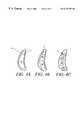
- FIG. 3Ais a cross-sectional view of an impeller blade taken generally along the line A—A of FIG. 2;
- FIG. 3Bis an enlargement of the blade-pump housing interface portion of FIG. 3A;
- FIG. 3Cis an alternative impeller blade shape
- FIGS. 4A, 4 B and 4 Cillustrate various possible locations of magnet material within a blade
- FIG. 5is a left-hand end view of a possible winding geometry taken generally along the line S—S of FIG. 1;
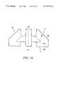
- FIG. 6is a diagrammatic cross-sectional view of an alternative embodiment of the invention as an axial pump
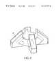
- FIG. 7is an exploded, perspective view of a centrifugal pump assembly according to a further embodiment of the invention.
- FIG. 8is a perspective view of the impeller of the assembly of FIG. 7;
- FIG. 9is a perspective, cut away view of the impeller of FIG. 8 within the pump assembly of FIG. 7;
- FIG. 10is a side section indicative view of the impeller of FIG. 8;
- FIG. 11is a detailed view in side section of edge portions of the impeller of FIG. 10;
- FIG. 12is a block diagram of an electronic driver circuit for the pump assembly of FIG. 7;
- FIG. 13is a graph of head versus flow for the pump assembly of FIG. 7;
- FIG. 14is a graph of pump efficiency versus flow for the pump assembly of FIG. 7;
- FIG. 15is a graph of electrical power consumption versus flow for the pump assembly of FIG. 7;
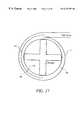
- FIG. 16is a plan, section view of the pump assembly showing a volute arrangement according to a preferred embodiment
- FIG. 17is a plan, section view of a pump assembly showing an alternative volute arrangement
- FIG. 18is a plan view of an impeller according to a further embodiment of the invention.
- FIG. 19is a plan view of an impeller according to a further embodiment of the invention.
- FIG. 20is a perspective view of an impeller according to a further embodiment of the invention.
- the pump assemblies according to various preferred embodiments to be described belowall have particular, although not exclusive, application for implantation in a mammalian body so as to at least assist, if not take over, the function of the mammalian heart. In practice this is performed by placing the pump assembly entirely within the body of the mammal and connecting the pump between the left ventricle and the aorta so as to assist left side heart function. It may also be connected to the right ventricle and pulmonary artery to assist the right side of the heart.
- the pump assemblyincludes an impeller which is fully sealed within the pump body and so does not require a shaft extending through the pump body to support it.
- the impelleris suspended, in use, within the pump body by, at least, the operation of hydrodynamic forces imparted as a result of the interaction between the rotating impeller, the internal pump walls and the fluid which the impeller causes to be urged from an inlet of the pump assembly to an outlet thereof.
- a preferred embodiment of the inventionis the centrifugal pump 1 , as depicted in FIGS. 1 and 2, intended for implantation into a human body, in which case the fluid referred to below is blood.
- the pump housing 2can be fabricated in two parts, a front part 3 in the form of a housing body and a back part 4 in the form of a housing cover, with a smooth join therebetween, for example at 5 in FIG. 1 .
- the pump 1has an axial inlet 6 and a tangential outlet 7 .
- the rotating part or impeller 100is of very simple form, comprising only blades 8 and a blade support 9 to hold those blades fixed relative to each other. The blades may be curved as depicted in FIG.
- This rotating part 100will hereafter be called the impeller 100 , but it also serves as a bearing component and as the rotor of a motor configuration as to be further described below whereby a torque is applied by electromagnetic means to the impeller 100 .
- the impellerhas no shaft and that the fluid enters the impeller from the region of its axis RR. Some of the fluid passes in front of the support cone 9 and some behind it, so that the pump 1 can be considered of two-sided open type, as compared to conventional open centrifugal pumps, which are only open on the front side.
- Approximate dimensions found adequate for the pump 1 to perform as a ventricular assist device, when operating at speeds in the range 2,000 rpm to 4,000 rpm,are outer blade diameter 40 mm, outer housing average diameter 60 mm, and housing axial length 40 mm.
- the gapsare made small because this leakage flow lowers the pump hydrodynamic efficiency.
- the gapsare made slightly smaller than is conventional in order that the leakage flow can be utilised to create a hydrodynamic bearing.
- the bladesmust also be tapered as depicted in FIGS. 3A and 3B, so that the gap 104 is larger at the leading edge 102 of the blade 8 than at the trailing edge 103 .
- the fluid 105 which passes through the gapthus experiences a wedge shaped restriction which generates a thrust, as described in Reynolds' theory of lubrication (see, for example, “Modern Fluid Dynamics, Vol. 1 Incompressible Flow”, by N. Curle and H. J. Davies, Van Nostrand, 1968).
- the thrustis proportional to the square of the blade thickness at the edge, and thus thick blades are favoured, since if the proportion of the pump cavity filled by blades is constant, then the net thrust force will be inversely proportional to the number of blades.
- the blade edgescan be made to extend as tails from thin blades as depicted in FIG. 3C in order to increase the blade area adjacent the walls.
- the tailsjoin adjacent blades so as to form a complete shroud with wedges or tapers incorporated therein.
- a shroud designas well as other variations on the blade structure will be described later in this specification.
- the housing front face 10can be made conical, with an angle of around 450 so that it provides both axial and radial hydrodynamic forces. Other angles are suitable that achieve the functional requirements of this pump including the requirements for both axial and radial hydrodynamic forces.
- the housing back face 11can include a roughly conical extension 12 pointing into the pump cavity 106 , to eliminate or minimise the effect of the flow stagnation point on the axis of the back housing.
- extension 12can resemble an impeller eye to make the flow mixed.
- the housing back face 11is made flat over the bearing surfaces, i.e. under the blade edges. With this the case, a slacker tolerance on the alignment between the axes of the front part 3 and back part 4 of the housing 2 is permissible.
- An alternativeis to make the back face 11 conical at the bearing surfaces, with taper in the opposite direction to the front face 10 , so that the hydrodynamic forces from the back face will also have radial components. Tighter tolerance on the axes alignment would then be required, and some of the flow would have to undergo a reversal in its axial direction. Again a roughly conical extension (like 12 ) will be needed. There may be some advantage in making the housing surfaces and blade edges non-straight, with varying tangent angle, although this will impose greater manufacturing complexity.
- the amount of material removedsimply varies linearly or approximately linearly across the blade.
- the resulting blade edgesare then planes at a slight inclination to the back face.
- the initial blade edgesare curved and the taper only removes a relatively small amount of material so they still appear curved.
- Alternative taper shapescan include a step in the blade edge, though the corner in that step would represent a stagnation line posing a thrombosis risk.
- the hydrodynamic forceis maximal if the gap at the leading edge is approximately double that at the trailing edge.
- the taperwhich equals the leading edge gap minus the trailing edge gap, should be chosen to match a nominal minimum gap, once the impeller has shifted towards that edge.
- Dimensions which have been found to give adequate thrust forcesare a tape r of around 0.05 mm for a nominal minimum gap of around 0.05 mm, and an average circumferential blade edge thickness of around 5 mm for 4 blades.
- the taperis measured within the plane perpendicular to the axis.
- the axial length of the housing between the front and back faces at any positionshould then be made about 0.2 mm greater than the axial length of the blade, when it is coaxial with the housing, so that the minimum gaps are both about 0.1 mm axially when the impeller 100 is centrally positioned within the housing 2 . Then, for example, if the impeller shifts axially by 0.05 mm, the minimum gaps will be 0.05 mm at one face and 0.15 mm at the other face. The thrust increases with decreasing gap and would be much larger from the 0.05 mm gap than from the 0.15 mm gap, about 14 times larger for the above dimensions. Thus there is a net restoring force away from the smaller gap.
- the impellerwill continually shift its position and alignment, varying the gaps in such a way that the total force and torque on the impeller 100 match that demanded by inertia.
- the gapsare so small, however, that the variation in hydrodynamic efficiency will be small, and the pumping action of the blades will be approximately the same as when the impeller is centrally located.
- a major advantage of the open blades of the present inventionis that a fluid element that does pass through a blade edge gap will have very short residence time in that gap, around 2 ⁇ 10 ⁇ 3 S, and the fluid element will most likely be swept though the pump without passing another blade edge.
- One method of minimising the bulk radial hydrodynamic forceis to use straight radial blades so that pressure acting on the blade sides has virtually no radial component.
- the radial force on the impellerdepends critically on the shape of the output flow collector or volute 13 .
- the shapeshould be designed to minimise the radial impeller force over the desired range of pump speeds, without excessively lowering the pump efficiency.
- the optimal shapewill have a roughly helical perimeter between the “cut water” and outlet.
- the radial forcecan also be reduced by the introduction of an internal division in the volute 13 to create a second output flow collector passage, with tongue approximately diametrically opposite to the tongue of the first passage.
- FIG. 2An indicative plan view of impeller 100 relative to housing 2 is shown in FIG. 2 having a concentric volute 13 .
- FIG. 17illustrates the alternative volute arrangement comprising a split volute created by volute barrier 107 which causes volute 108 in a first hemisphere of the housing 2 to split into first half volute 109 and second half volute 110 over the second hemisphere.
- the hemispheresare defined respectively on each side of a diameter of the housing 2 which passes through or near exit point 111 of outlet 7 .
- concentric volutescan be utilised, particularly where specific speed is relatively low.
- a vaneless diffusermay also reduce the radial force.
- the blade support cone 9must then be shaped to minimise axial thrust on the impeller and minimise disturbance to the flow over the range of speeds, while maintaining sufficient strength to prevent relative blade movement.
- the key design parameter affecting the axial forceis the angle of the cone.
- the coneis drawn in FIG. 1 as having the same internal diameter as the blades, which may aid manufacture. However, the cone could be made with larger or smaller internal diameter to the blades.
- any bulk hydrodynamic axial force on themcan be balanced by shaping the support cone to produce an opposite bulk hydrodynamic axial force on it.
- the means of providing the driving torque on the impeller 100 of the preferred embodiment of the inventionis to encapsulate permanent magnets 14 in the blades 8 of the impeller 100 and to drive them with a rotating magnetic field pattern from oscillating currents in windings 15 and 16 , fixed relative to the housing 2 .
- Magnets of high remanencesuch as sintered rare-earth magnets should be used to maximise motor efficiency.
- the magnetsshould be aligned axially or approximately axially, with alternating polarity for adjacent blades. Thus there must be an even number of blades.
- blade numberis preferred for the bearing force, and since two blades would not have sufficient bearing stiffness to rotation about an axis through the blades and perpendicular to the pump housing (unless the blades are very curved), four blades are recommended. A higher number of blades, for example 6 or 8 will also work.
- FIG. 4Some possible options for locating the magnets 14 within the blades 8 are shown in FIG. 4 .
- the coatingshould also be sufficiently durable especially at blade corners to withstand rubbing during start-up or during inadvertent bearing touch down.
- inside walls of the pump housing 2are also coated with a biologically compatible and wear resistant material such as diamond coating or titanium nitride so that wear on both of the touching surfaces is minimised.
- a biologically compatible and wear resistant materialsuch as diamond coating or titanium nitride
- An acceptable coating thicknessis approximately 1 micron.
- a suitable impeller manufacturing methodis to die-press the entire impeller, blades and support cone, as a single axially aligned magnet.
- the die-pressingis much simplified if near axially uniform blades are used (blades with an overhang such as in FIG. 3C are precluded).
- the crushed rare-earth particlesmust be aligned in an axial magnetic field.
- This method of die-pressing with parallel alignment directionis cheaper for rare-earth magnets, although it produces slightly lower remanence magnets.
- the tolerance in die-pressingis poor, and grinding of the tapered blade edges is required.
- the magnet impellercan be coated, for example by physical vapour deposition, of titanium nitride for example, or by chemical vapour deposition, of a thin diamond coating or a teflon coating.
- the magnet materialcan be potted in titanium or a polymeric housing which is then, in turn, coated with a biologically compatible and tough material such as diamond coating or titanium nitride.
- the impellermust be placed in a special pulse magnetisation fixture, with an individual coil surrounding each blade.
- the support conemay acquire some magnetisation near the blades, with negligible influence.
- FIG. 4 B and FIG. 4CAlternative magnet locations are sketched in FIG. 4 B and FIG. 4C in which quadrilateral or circular cross-section magnets 14 are inserted into the blades. Sealing and smoothing of the blade edges over the insertion holes is then required to reinstate the taper.
- All edges in the pumpshould be radiused and surfaces smoothed to avoid possible damage to formed elements of the blood.
- the windings 15 and 16 of the preferred embodimentare slotless or air-gap windings, following the blade curvature, with the same pole number as the impeller, namely four poles in the preferred embodiment.
- a ferromagnetic iron yoke 17 of conical form for the front winding and an iron ferromagnetic yoke 18 of annular form for the back windingmay be placed on the outside of the windings to increase the magnetic flux densities and hence increase motor efficiency.
- the winding thicknessesshould be designed for maximum motor efficiency, with the sum of their axial thicknesses somewhat less than but comparable to the magnet axial length.
- the yokescan be made of solid ferromagnetic material such as iron.
- the yokes 17can be laminated, for example by helically winding thin strip, or can be made of iron/powder epoxy composite. Alternatively they can be helically wound to reduce iron losses.
- the yokesshould be positioned such that there is zero net axial magnetic force on the impeller when it is positioned centrally in the housing.
- the magnetic forceis unstable and increases linearly with axial displacement of the impeller away from the central position, with the gradient being called the positive stiffness of the magnetic force. This unstable magnetic force must be countered by the hydrodynamic bearings, and so the stiffness should be made as small as possible. Choosing the yoke thickness such that the flux density is at the saturation level reduces the stiffness and gives minimum mass.
- FIG. 5depicts one suitable topology for the front face winding 15 .
- the back face winding 16looks similar from the back end of the motor, except the hole on the axis is smaller.
- Each windinghas three phases, A, B and C, and two coils connected in series or parallel per phase.
- Each coilcomprises a number of turns of an insulated conductor such as copper, with the number of turns chosen to suit the desired voltage.
- the conductormay need to be stranded to reduce eddy losses.
- the winding constructioncan be simplified by laying the coils around pins protruding from a temporary conical former, the pins shown as dots in two rings of six pins each in FIG. 5 .
- the coilsare labelled alphabetically in the order in which they would be layed, coils a and d for phase A, b and e for phase B, and c and f for phase C.
- the coil locationscan be defined by thin curved fins, running between the pins in FIG. 5, along the boundary between the coils.
- the winding connection of the preferred embodimentis for three wires, one wire per phase, to connect a sensorless electronic controller to winding 15 , three wires to pass between windings 15 and 16 , and for a neutral point termination of the wires within winding 16 .
- a neutral lead, N in FIG. 5, between the controller and the neutral pointis optional.
- a standard sensorless controllercan be used, in which two out of six semiconducting switches in a three phase bridge are turned on at any one time, with the switching synchronised with the impeller position via the back-emf in the unenergised phase.
- the two housing components 3 and 4are made by injection moulding from non-conducting plastic materials such as Lexan polycarbonate plastic or ceramics.
- the windings and yokesare encapsulated within the housing during fabrication moulding. In this way, the separation between the winding and the magnets is minimised, increasing the motor efficiency, and the housing is thick, increasing its mechanical stiffness.
- the windingscan be positioned outside the housing, of thickness at least around 2 mm for sufficient stiffness.
- the housing material plasticis hygroscopic or if the windings are outside the housing, it may be necessary to first enclose the windings and yoke in a very thin impermeable shell.
- the shellshould be non-conducting (such as ceramic or plastic), but titanium of around 0.1 mm to 0.2 mm thickness would give sufficiently low eddy losses. Encapsulation within such a shell would be needed to prevent winding movement.
- the windingscan be moulded into the front and back housing parts.
- the combining of the motor and bearing components into the impeller in the preferred embodimentprovides several key advantages.
- the rotorconsequently has very simple form, with the only cost of the bearing being tight manufacturing tolerances.
- the rotor massis very low, minimising the bearing force needed to overcome weight. Also, with the bearings and the motor in the same region of the rotor, the bearings forces are smaller than if they had to provide a torque to support magnets at an extremity of the rotor.
- a disadvantage of the combination of functions in the impelleris that its design is a coupled problem.
- the optimisationshould ideally link the fluid dynamics, magnetics and bearing thrust calculations.
- the blade thicknesscan be first roughly sized to give adequate motor efficiency and sufficient bearing forces with a safety margin.
- both requirementsare met for four blades of approximate average circumferential thickness 5 mm.
- the housing, blade, and support cone shapescan then be designed using computational fluid dynamics, maintaining the above minimum average blade thickness.
- the motor statori.e. winding and yoke, can be optimised for maximum motor efficiency.
- FIG. 6depicts an alternative embodiment of the invention as an axial pump.
- the pump housingis made of two parts, a front part 19 and a back part 20 , joined for example at 21 .
- the pumphas an axial inlet 22 and axial outlet 23 .
- the impellercomprises only blades 24 mounted on a support cylinder 25 of reducing radius at each end.
- An important feature of this embodimentis that the blade edges are tapered to generate hydrodynamic thrust forces which suspend the impeller. These forces could be used for radial suspension alone from the straight section 26 of the housing, with some alternative means used for axial suspension, such as stable axial magnetic forces or a conventional tapered-land type hydrodynamic thrust bearing.
- FIG. 6proposes a design which uses the tapered blade edges to also provide an axial hydrodynamic bearing.
- the housingis made with a reducing radius at its ends to form a front face 27 and a back face 28 from which the axial thrusts can suspend the motor axially.
- Magnetsare embedded in the blades with blades having alternating polarity and four blades being recommended. Iron in the outer radius of the support cylinder 25 can be used to increase the magnet flux density. Alternatively, the magnets could be housed in the support cylinder and iron could be used in the blades.
- a slotless helical winding 29is recommended, with outward bending end-windings 30 at one end to enable insertion of the impeller and inward bending windings 31 at the other end to enable insertion of the winding into a cylindrical magnetic yoke 32 .
- the windingcan be encapsulated in the back housing part 20 .
- FIGS. 7 to 15 inclusivethere is shown a further preferred embodiment of the pump assembly 200 .
- the pump assembly 200comprises a housing body 201 adapted for bolted connection to a housing cover 202 and so as to define a centrifugal pump cavity 203 therewithin.
- the cavity 203houses an impeller 204 adapted to receive magnets 205 within cavities 206 defined within blades 207 .
- the blades 207are supported from a support cone 208 .
- a body winding 209symmetrically mounted around inlet 210 and housed between the housing body 201 and a body yoke 211 .
- cover winding 212located within winding cavity 213 which, in turn, is located within housing cover 202 and closed by cover yoke 214 .
- the windings 212 and 209are supplied from the electronic controller of FIG. 12 .
- the windingsare arranged to receive a three phase electrical supply and so as to set up a rotating electrical field within cavity 203 which exerts a torque on magnets 205 within the impeller 204 so as to urge the impeller 204 to rotate substantially about central axis TT of cavity 203 and in line with the longitudinal axis of inlet 210 .
- the impeller 204is caused to rotate so as to urge fluid (in this case blood liquid) around volute 215 and through outlet 216 .
- the assemblyis bolted together in the manner indicated by screws 217 .
- the yokes 211 , 214are held in place by fasteners 218 .
- press fittingis possible provided sufficient integrity of seal can be maintained.
- FIG. 8shows the impeller 204 of this embodiment and clearly shows the support cone 208 from which the blades 207 extend.
- the axial cavity 219which is arranged, in use, to be aligned with the longitudinal axis of inlet 210 and through which blood is received for urging by blades 207 is clearly visible.
- FIG. 9shows the axial cavity 219 and also the magnet cavities 206 located within each blade 207 .
- the preferred cone structure 220 extending from housing cover 202 aligned with the axis of inlet 210 and axial cavity 219 of impeller 204is also shown.
- FIG. 10is a side section, indicative view of the impeller 204 defining the orientations of central axis FF, top taper edge DD and bottom taper edge BB, which tapers are illustrated in FIG. 11 in side section view.
- FIG. 11Ais a section of a blade 207 of impeller 204 taken through plane DD as defined in FIG. 10 and shows the top edge 221 to be profiled from a leading edge 223 to a trailing edge 224 as follows: central portion 227 comprises an ellipse having a semi-major axis of radius 113 mm and a semi-minor axis of radius 80 mm subtended on either side by a region of no radius and then followed by leading conical surface 225 and trailing conical surface 226 on either side thereof as illustrated in FIG. 11 A.
- the leading edge 223is radiused as illustrated.
- FIG. 11Billustrates in cross-section the bottom edge 222 of blade 207 cut along plane BB of FIG. 10 .
- the bottom edgeincludes cap 228 utilised for sealing magnet 205 within cavity 206 .
- substantially the entire edgecomprises a straight taper with a radius of 0.05 mm at leading edge 229 and a radius of 0.25 mm at trailing edge 230 .
- the blade 207is 5.4 mm in width excluding the radii at either end.
- FIG. 12comprises a block diagram of the electrical controller suitable for driving the pump assembly 200 and comprises a three phase commutation controller 232 adapted to drive the windings 209 , 212 of the pump assembly.
- the commutation controller 232determines relative phase and frequency values for driving the windings with reference to set point speed input 233 derived from physiological controller 234 which, in turn, receives control inputs 235 comprising motor current input and motor speed (derived from the commutation controller 232 ), patient blood flow 236 , and venous oxygen saturation 237 .
- FIG. 13is a graph of pressure against flow for the pump assembly 200 where the fluid pumped is 18% glycerol for impeller rotation velocity over the range 1500 RPM to 2500 RPM.
- the 18% glycerol liquidis believed to be a good analogue for blood under certain circumstances.
- FIG. 14graphs pump efficiency against flow for the same fluid over the same speed ranges as for FIG. 13 .
- FIG. 15is a graph of electrical power consumption against flow for the same fluid over the same speed ranges as for FIG. 13 .
- the common theme running through the first, second and third embodiments described thus faris the inclusion in the impeller of a taper or other deformed surface which, in use, moves relative to the adjacent housing wall thereby to cause a restriction with respect to the line of movement of the taper or deformity thereby to generate thrust upon the impeller which includes a component substantially normal to the line of movement of the surface and also normal to the adjacent internal pump wall with respect to which the restriction is defined for fluid located therebetween.
- At least one set of surfacesmust be angled with respect to the longitudinal axis of the impeller (preferably at approximately 45° thereto) thereby to generate or resolve opposed radial forces and an axial force which can be balanced by a corresponding axial force generated by at least one other tapered or deformed surface located elsewhere on the impeller.
- top surfaces of the blades 8 , 207are angled at approximately 450 with respect to the longitudinal axis of the impeller 100 , 204 and arranged for rotation with respect to the internal walls of a similarly angled conical pump housing.
- the top surfacesare deformed so as to create the-necessary restriction in the gap between the top surfaces of the blades and the internal walls of the conical pump housing thereby to generate a thrust which can be resolved to both radial and axial components.
- the bottom faces of the blades 8 , 207comprise surfaces substantially lying in a plane at right angles to the axis of rotation of the impeller and, with their deformities define a gap with respect to a lower inside face of the pump housing against which a substantially only axial thrust is generated.
- Such arrangementscan include a double cone arrangement where the conical top surface of the blades is mirrored in a corresponding bottom conical surface.
- the only concern with this arrangementis the increased depth of pump which can be a problem for in vivo applications where size minimisation is an important criteria.
- FIG. 18a further embodiment of the invention is illustrated comprising a plan view of the impeller 300 forming part of a “channel” pump.
- the blades 301have been widened relative to the blades 207 of the third embodiment to the point where they are almost sector-shaped and the flow gaps between adjacent blades 301 , as a result, take the form of a channel 302 , all in communication with axial cavity 303 .
- impeller 304includes sector-shaped blades 305 having curved leading and trailing portions 306 , 307 respectively thereby defining channels 308 having fluted exit portions 309 .
- the radial and axial hydrodynamic forcesare generated by appropriate profiling of the top and bottom faces of the blades 301 , 305 (not shown in FIGS. 18 and 19 ).
- a further embodiment of a pump assembly according to the inventioncomprises an impeller 310 as illustrated in FIG. 20 where, conceptually, the upper and lower surfaces of the blades of previous embodiments are interconnected by a top shroud 311 and a bottom shroud 312 .
- the blades 313can be reduced to a very small width as the hydrodynamic behaviour imparted by their surfaces in previous embodiments is now given effect by the profiling of the shrouds 311 , 312 which, in this instance, comprises a series of smooth-edged wedges with the leading surface of one wedge directly interconnected to the trailing edge of the next leading wedge 314 .
- top shroud 311is of overall conical shape thereby to impart both radial and axial thrust forces whilst the bottom shroud 312 is substantially planar thereby to impart substantially only axial thrust forces.
- the pump assembly 1 , 200is applicable to pump fluids such as blood on a continuous basis. With its expected reliability it is particularly applicable as an in vivo heart assist pump.
- the pump assemblycan also be used with advantage for the pumping of other fluids where damage to the fluid due to high shear stresses must be avoided or where leakage of the fluid must be prevented with a very high degree of reliability—for example where the fluid is a dangerous fluid.
Landscapes
- Engineering & Computer Science (AREA)
- Health & Medical Sciences (AREA)
- Heart & Thoracic Surgery (AREA)
- Mechanical Engineering (AREA)
- Cardiology (AREA)
- General Engineering & Computer Science (AREA)
- Anesthesiology (AREA)
- Biomedical Technology (AREA)
- Hematology (AREA)
- Life Sciences & Earth Sciences (AREA)
- Animal Behavior & Ethology (AREA)
- General Health & Medical Sciences (AREA)
- Public Health (AREA)
- Veterinary Medicine (AREA)
- Fluid Mechanics (AREA)
- Physics & Mathematics (AREA)
- External Artificial Organs (AREA)
- Structures Of Non-Positive Displacement Pumps (AREA)
Abstract
Description
Claims (26)
Priority Applications (10)
| Application Number | Priority Date | Filing Date | Title |
|---|---|---|---|
| US09/299,038US6250880B1 (en) | 1997-09-05 | 1999-04-23 | Rotary pump with exclusively hydrodynamically suspended impeller |
| US09/734,532US6609883B2 (en) | 1997-05-09 | 2000-12-11 | Rotary pump with hydrodynamically suspended impeller |
| US09/893,319US6638011B2 (en) | 1997-09-05 | 2001-06-26 | Rotary pump with exclusively hydrodynamically suspended impeller |
| US10/634,211US6966748B2 (en) | 1997-09-05 | 2003-08-05 | Rotary pump with exclusively hydrodynamically suspended impeller |
| US10/634,538US7156802B2 (en) | 1997-09-05 | 2003-08-05 | Rotary pump with hydrodynamically suspended impeller |
| US11/212,227US7476077B2 (en) | 1997-09-05 | 2005-08-26 | Rotary pump with exclusively hydrodynamically suspended impeller |
| US11/238,400US20060030748A1 (en) | 1997-09-05 | 2005-09-29 | Rotary pump with hydrodynamically suspended impeller |
| US12/347,263US8002518B2 (en) | 1997-09-05 | 2008-12-31 | Rotary pump with hydrodynamically suspended impeller |
| US13/181,452US8366381B2 (en) | 1997-09-05 | 2011-07-12 | Rotary pump with hydrodynamically suspended impeller |
| US13/758,887US20130225910A1 (en) | 1997-09-05 | 2013-02-04 | Rotary Pump with Hydrodynamically Suspended Impeller |
Applications Claiming Priority (2)
| Application Number | Priority Date | Filing Date | Title |
|---|---|---|---|
| AUPO9027AAUPO902797A0 (en) | 1997-09-05 | 1997-09-05 | A rotary blood pump with hydrodynamically suspended impeller |
| PCT/AU1998/000725WO1999012587A1 (en) | 1997-09-05 | 1998-09-07 | A rotary pump with hydrodynamically suspended impeller |
Related Parent Applications (1)
| Application Number | Title | Priority Date | Filing Date |
|---|---|---|---|
| PCT/AU1998/000725ContinuationWO1999012587A1 (en) | 1997-05-09 | 1998-09-07 | A rotary pump with hydrodynamically suspended impeller |
Related Child Applications (2)
| Application Number | Title | Priority Date | Filing Date |
|---|---|---|---|
| US09/299,038Continuation-In-PartUS6250880B1 (en) | 1997-09-05 | 1999-04-23 | Rotary pump with exclusively hydrodynamically suspended impeller |
| US09/734,532ContinuationUS6609883B2 (en) | 1997-05-09 | 2000-12-11 | Rotary pump with hydrodynamically suspended impeller |
Publications (1)
| Publication Number | Publication Date |
|---|---|
| US6227797B1true US6227797B1 (en) | 2001-05-08 |
Family
ID=3803312
Family Applications (7)
| Application Number | Title | Priority Date | Filing Date |
|---|---|---|---|
| US09/281,608Expired - LifetimeUS6227797B1 (en) | 1997-05-09 | 1999-03-30 | Rotary pump with hydrodynamically suspended impeller |
| US09/734,532Expired - LifetimeUS6609883B2 (en) | 1997-05-09 | 2000-12-11 | Rotary pump with hydrodynamically suspended impeller |
| US10/634,538Expired - LifetimeUS7156802B2 (en) | 1997-09-05 | 2003-08-05 | Rotary pump with hydrodynamically suspended impeller |
| US11/238,400AbandonedUS20060030748A1 (en) | 1997-09-05 | 2005-09-29 | Rotary pump with hydrodynamically suspended impeller |
| US12/347,263Expired - Fee RelatedUS8002518B2 (en) | 1997-09-05 | 2008-12-31 | Rotary pump with hydrodynamically suspended impeller |
| US13/181,452Expired - Fee RelatedUS8366381B2 (en) | 1997-09-05 | 2011-07-12 | Rotary pump with hydrodynamically suspended impeller |
| US13/758,887AbandonedUS20130225910A1 (en) | 1997-09-05 | 2013-02-04 | Rotary Pump with Hydrodynamically Suspended Impeller |
Family Applications After (6)
| Application Number | Title | Priority Date | Filing Date |
|---|---|---|---|
| US09/734,532Expired - LifetimeUS6609883B2 (en) | 1997-05-09 | 2000-12-11 | Rotary pump with hydrodynamically suspended impeller |
| US10/634,538Expired - LifetimeUS7156802B2 (en) | 1997-09-05 | 2003-08-05 | Rotary pump with hydrodynamically suspended impeller |
| US11/238,400AbandonedUS20060030748A1 (en) | 1997-09-05 | 2005-09-29 | Rotary pump with hydrodynamically suspended impeller |
| US12/347,263Expired - Fee RelatedUS8002518B2 (en) | 1997-09-05 | 2008-12-31 | Rotary pump with hydrodynamically suspended impeller |
| US13/181,452Expired - Fee RelatedUS8366381B2 (en) | 1997-09-05 | 2011-07-12 | Rotary pump with hydrodynamically suspended impeller |
| US13/758,887AbandonedUS20130225910A1 (en) | 1997-09-05 | 2013-02-04 | Rotary Pump with Hydrodynamically Suspended Impeller |
Country Status (8)
| Country | Link |
|---|---|
| US (7) | US6227797B1 (en) |
| EP (1) | EP1019116B1 (en) |
| JP (1) | JP3725027B2 (en) |
| CN (1) | CN1278188A (en) |
| AT (1) | ATE292987T1 (en) |
| AU (1) | AUPO902797A0 (en) |
| DE (1) | DE69829766T2 (en) |
| WO (1) | WO1999012587A1 (en) |
Cited By (157)
| Publication number | Priority date | Publication date | Assignee | Title |
|---|---|---|---|---|
| US6368083B1 (en)* | 1996-02-20 | 2002-04-09 | Kriton Medical, Inc. | Sealless rotary blood pump |
| US20030091450A1 (en)* | 2001-11-13 | 2003-05-15 | Davis William D. | Pump with electrodynamically supported impeller |
| US6623475B1 (en)* | 1998-12-02 | 2003-09-23 | Impella Cardiosystems Ag | Blood pump without bearing |
| US6676383B2 (en)* | 2001-08-16 | 2004-01-13 | Levitronix Llc | Method and a pump apparatus for the generation of an adjustable, substantially constant volume flow of a fluid and a use of this method |
| US20040030216A1 (en)* | 1997-09-05 | 2004-02-12 | Woodard John Campbell | Rotary pump with hydrodynamically suspended impeller |
| US20040028525A1 (en)* | 1997-09-05 | 2004-02-12 | Woodard John C. | Rotary pump with exclusively hydrodynamically suspended impeller |
| US20040062648A1 (en)* | 2002-09-30 | 2004-04-01 | Makinson Ian Douglas | Impeller |
| US6761532B2 (en) | 2001-03-14 | 2004-07-13 | Vascor, Inc. | Touch down of blood pump impellers |
| US20050000580A1 (en)* | 2002-12-20 | 2005-01-06 | Tranovich Stephen J. | Predictive maintenance and initialization system for a digital servovalve |
| US20050025630A1 (en)* | 1999-04-23 | 2005-02-03 | Ayre Peter Joseph | Rotary blood pump and control system therefor |
| DE10330434A1 (en)* | 2003-07-04 | 2005-02-03 | Jostra Ag | Centrifugal pump |
| WO2005032620A1 (en)* | 2003-10-09 | 2005-04-14 | Ventracor Limited | Impeller |
| US20050084398A1 (en)* | 2003-09-18 | 2005-04-21 | Wampler Richard K. | Rotary blood pump |
| US20050196293A1 (en)* | 1999-04-23 | 2005-09-08 | Ayre Peter J. | Rotary blood pump and control system therefor |
| USD514126S1 (en) | 2004-03-10 | 2006-01-31 | Ventracor Limited | Impeller |
| USD514125S1 (en) | 2004-09-03 | 2006-01-31 | Ventracor Limited | Impeller |
| US20060024182A1 (en)* | 2004-03-18 | 2006-02-02 | Mustafa Akdis | Pump |
| US20060083642A1 (en)* | 2004-10-18 | 2006-04-20 | Cook Martin C | Rotor stability of a rotary pump |
| US20060122456A1 (en)* | 2004-12-03 | 2006-06-08 | Larose Jeffrey A | Wide blade, axial flow pump |
| US20060245959A1 (en)* | 2005-04-29 | 2006-11-02 | Larose Jeffrey A | Multiple rotor, wide blade, axial flow pump |
| US20070053781A1 (en)* | 2003-05-15 | 2007-03-08 | Davis William D | Pump with electrodynamically supported impeller |
| US20070052389A1 (en)* | 2005-07-19 | 2007-03-08 | Michiel Kooij | Battery receptacle |
| US20070054256A1 (en)* | 2005-09-06 | 2007-03-08 | Jeremy Low | Mock circulatory apparatus |
| US20070078293A1 (en)* | 2005-10-05 | 2007-04-05 | Shambaugh Charles R Jr | Impeller for a rotary ventricular assist device |
| US20070142696A1 (en)* | 2005-12-08 | 2007-06-21 | Ventrassist Pty Ltd | Implantable medical devices |
| US20070238915A1 (en)* | 2006-03-23 | 2007-10-11 | Woodard John C | System for preventing diastolic heart failure |
| EP1847281A1 (en) | 2006-04-20 | 2007-10-24 | Ventrassist Pty Ltd | System and method of controlling a rotary blood pump |
| US20070247968A1 (en)* | 2006-04-21 | 2007-10-25 | V & P Scientific, Inc. | Sandwich magnetic stir elements for stirring the contents of vessels |
| US20070265703A1 (en)* | 2006-05-09 | 2007-11-15 | Ventrassist Pty Ltd. | Pulsatile control system for a rotary blood pump |
| US20070270633A1 (en)* | 2003-10-31 | 2007-11-22 | Cook Martin C | Blood Pump Comprising Polymeric Components |
| US20070280841A1 (en)* | 2006-01-13 | 2007-12-06 | Larose Jeffrey A | Hydrodynamic thrust bearings for rotary blood pumps |
| US20080114339A1 (en)* | 2006-03-23 | 2008-05-15 | The Penn State Research Foundation | Heart assist device with expandable impeller pump |
| US20080133006A1 (en)* | 2006-10-27 | 2008-06-05 | Ventrassist Pty Ltd | Blood Pump With An Ultrasonic Transducer |
| US20080200750A1 (en)* | 2006-11-17 | 2008-08-21 | Natalie James | Polymer encapsulation for medical device |
| WO2008152425A1 (en) | 2007-06-14 | 2008-12-18 | Calon Cardio Technology Limited | Reduced diameter axial rotary pump for cardiac assist |
| US20090060743A1 (en)* | 2004-09-17 | 2009-03-05 | The Penn State Research Foundation | Expandable impeller pump |
| US20090203957A1 (en)* | 2008-02-08 | 2009-08-13 | Larose Jeffrey A | Ventricular assist device for intraventricular placement |
| US20090306492A1 (en)* | 2005-07-12 | 2009-12-10 | Nicholas Andrew Earl | Restraining device for a percutaneous lead assembly |
| US20100016960A1 (en)* | 1997-10-09 | 2010-01-21 | Bolling Steven F | Implantable Heart Assist System And Method Of Applying Same |
| US20100106225A1 (en)* | 2003-08-01 | 2010-04-29 | Ventracor Limited | Transcutaneous Power And/Or Data Transceiver |
| US20100160801A1 (en)* | 2007-05-10 | 2010-06-24 | Setsuo Takatani | Cardiac function change evaluating device |
| AU2004220728B2 (en)* | 2004-10-14 | 2010-06-24 | Thoratec Corporation | Improvements in Rotor Stability of a Rotary Pump |
| EP2150289A4 (en)* | 2007-04-25 | 2010-11-24 | Robert Jarvik | BLOOD PUMP STORAGE WITH SEPARATE CONTACT SURFACES |
| US20100305692A1 (en)* | 2009-05-27 | 2010-12-02 | Thomas Douglas C | Monitoring of redundant conductors |
| US20110015465A1 (en)* | 2005-11-04 | 2011-01-20 | Peter Joseph Ayre | Control systems for rotary blood pumps |
| US7963905B2 (en) | 2006-10-11 | 2011-06-21 | Thoratec Corporation | Control system for a blood pump |
| US20120114504A1 (en)* | 2010-11-10 | 2012-05-10 | Hamilton Sundstrand Corporation | Vertical shaft pumping system |
| US20130022481A1 (en)* | 2011-07-20 | 2013-01-24 | Levitronix Gmbh | Magnetic rotor and rotary pump having a magnetic rotor |
| AU2006297779B2 (en)* | 2005-10-05 | 2013-02-28 | Heartware, Inc. | Axial flow pump with multi-grooved rotor |
| US8388649B2 (en) | 2001-05-21 | 2013-03-05 | Thoratec Corporation | Staged implantation of ventricular assist devices |
| US8485961B2 (en) | 2011-01-05 | 2013-07-16 | Thoratec Corporation | Impeller housing for percutaneous heart pump |
| AU2013205145B2 (en)* | 2005-10-05 | 2013-08-15 | Heartware, Inc. | Axial flow pump with multi-grooved rotor |
| US8535211B2 (en) | 2009-07-01 | 2013-09-17 | Thoratec Corporation | Blood pump with expandable cannula |
| US8551163B2 (en) | 2010-10-07 | 2013-10-08 | Everheart Systems Inc. | Cardiac support systems and methods for chronic use |
| US8591393B2 (en) | 2011-01-06 | 2013-11-26 | Thoratec Corporation | Catheter pump |
| US8597170B2 (en) | 2011-01-05 | 2013-12-03 | Thoratec Corporation | Catheter pump |
| US8632449B2 (en) | 2009-04-16 | 2014-01-21 | Bivacor Pty Ltd | Heart pump controller |
| US8636638B2 (en) | 2009-04-16 | 2014-01-28 | Bivacor Pty Ltd | Heart pump controller |
| US8672611B2 (en) | 2006-01-13 | 2014-03-18 | Heartware, Inc. | Stabilizing drive for contactless rotary blood pump impeller |
| US8690749B1 (en) | 2009-11-02 | 2014-04-08 | Anthony Nunez | Wireless compressible heart pump |
| US8721517B2 (en) | 2012-05-14 | 2014-05-13 | Thoratec Corporation | Impeller for catheter pump |
| US8827661B2 (en) | 2008-06-23 | 2014-09-09 | Thoratec Corporation | Blood pump apparatus |
| US8864643B2 (en) | 2011-10-13 | 2014-10-21 | Thoratec Corporation | Pump and method for mixed flow blood pumping |
| US8894561B2 (en) | 2012-03-05 | 2014-11-25 | Thoratec Corporation | Modular implantable medical pump |
| US8905910B2 (en) | 2010-06-22 | 2014-12-09 | Thoratec Corporation | Fluid delivery system and method for monitoring fluid delivery system |
| US20150047639A1 (en)* | 2003-06-20 | 2015-02-19 | Resmed Limited | Method and apparatus for improving the comfort of cpap |
| WO2015085076A1 (en)* | 2013-12-04 | 2015-06-11 | Heartware, Inc. | Molded vad |
| US9068572B2 (en) | 2010-07-12 | 2015-06-30 | Thoratec Corporation | Centrifugal pump apparatus |
| US9067005B2 (en) | 2008-12-08 | 2015-06-30 | Thoratec Corporation | Centrifugal pump apparatus |
| US9089635B2 (en) | 2010-06-22 | 2015-07-28 | Thoratec Corporation | Apparatus and method for modifying pressure-flow characteristics of a pump |
| US9091271B2 (en) | 2010-08-20 | 2015-07-28 | Thoratec Corporation | Implantable blood pump |
| US9107992B2 (en) | 2011-11-28 | 2015-08-18 | MI-VAD, Inc. | Ventricular assist device and method |
| US9133854B2 (en) | 2010-03-26 | 2015-09-15 | Thoratec Corporation | Centrifugal blood pump device |
| US9132215B2 (en) | 2010-02-16 | 2015-09-15 | Thoratee Corporation | Centrifugal pump apparatus |
| US9138518B2 (en) | 2011-01-06 | 2015-09-22 | Thoratec Corporation | Percutaneous heart pump |
| US20150283324A1 (en)* | 2012-11-14 | 2015-10-08 | Ams Research Corporation | Cell delivery device and system with anti-clumping feature and methods for pelvic tissue treatment |
| US9155827B2 (en) | 2010-02-17 | 2015-10-13 | Flow Forward Medical, Inc. | System and method to increase the overall diameter of veins |
| US9227001B2 (en) | 2010-10-07 | 2016-01-05 | Everheart Systems Inc. | High efficiency blood pump |
| US9308302B2 (en) | 2013-03-15 | 2016-04-12 | Thoratec Corporation | Catheter pump assembly including a stator |
| US9309862B2 (en)* | 2013-11-25 | 2016-04-12 | Halliburton Energy Services, Inc. | Nutating fluid-mechanical energy converter |
| US9327067B2 (en) | 2012-05-14 | 2016-05-03 | Thoratec Corporation | Impeller for catheter pump |
| US9358329B2 (en) | 2012-07-03 | 2016-06-07 | Thoratec Corporation | Catheter pump |
| US9366261B2 (en) | 2012-01-18 | 2016-06-14 | Thoratec Corporation | Centrifugal pump device |
| US9371826B2 (en) | 2013-01-24 | 2016-06-21 | Thoratec Corporation | Impeller position compensation using field oriented control |
| US9381285B2 (en) | 2009-03-05 | 2016-07-05 | Thoratec Corporation | Centrifugal pump apparatus |
| US9382908B2 (en) | 2010-09-14 | 2016-07-05 | Thoratec Corporation | Centrifugal pump apparatus |
| US9381288B2 (en) | 2013-03-13 | 2016-07-05 | Thoratec Corporation | Fluid handling system |
| US9410549B2 (en) | 2009-03-06 | 2016-08-09 | Thoratec Corporation | Centrifugal pump apparatus |
| US20160235900A1 (en)* | 2015-02-13 | 2016-08-18 | Thoratec Corporation | Impeller suspension mechanism for heart pump |
| US9421311B2 (en) | 2012-07-03 | 2016-08-23 | Thoratec Corporation | Motor assembly for catheter pump |
| US9427510B2 (en) | 2012-08-31 | 2016-08-30 | Thoratec Corporation | Start-up algorithm for an implantable blood pump |
| US9429160B2 (en) | 2012-03-23 | 2016-08-30 | Terumo Kabushiki Kaisha | Centrifugal pump and method of manufacturing centrifugal pump |
| US9446179B2 (en) | 2012-05-14 | 2016-09-20 | Thoratec Corporation | Distal bearing support |
| US9496924B2 (en) | 2010-12-10 | 2016-11-15 | Everheart Systems, Inc. | Mobile wireless power system |
| US9492599B2 (en) | 2012-08-31 | 2016-11-15 | Thoratec Corporation | Hall sensor mounting in an implantable blood pump |
| US9512852B2 (en) | 2006-03-31 | 2016-12-06 | Thoratec Corporation | Rotary blood pump |
| US9539380B2 (en) | 2011-08-17 | 2017-01-10 | Flow Forward Medical, Inc. | System and method to increase the overall diameter of veins and arteries |
| US9555174B2 (en) | 2010-02-17 | 2017-01-31 | Flow Forward Medical, Inc. | Blood pump systems and methods |
| US9556873B2 (en) | 2013-02-27 | 2017-01-31 | Tc1 Llc | Startup sequence for centrifugal pump with levitated impeller |
| US9623161B2 (en) | 2014-08-26 | 2017-04-18 | Tc1 Llc | Blood pump and method of suction detection |
| US9657519B2 (en) | 2014-01-30 | 2017-05-23 | Halliburton Energy Services, Inc. | Nutating fluid-mechanical energy converter to power wellbore drilling |
| US9662431B2 (en) | 2010-02-17 | 2017-05-30 | Flow Forward Medical, Inc. | Blood pump systems and methods |
| US9675738B2 (en) | 2015-01-22 | 2017-06-13 | Tc1 Llc | Attachment mechanisms for motor of catheter pump |
| US9675739B2 (en) | 2015-01-22 | 2017-06-13 | Tc1 Llc | Motor assembly with heat exchanger for catheter pump |
| US9713663B2 (en) | 2013-04-30 | 2017-07-25 | Tc1 Llc | Cardiac pump with speed adapted for ventricle unloading |
| US9770543B2 (en) | 2015-01-22 | 2017-09-26 | Tc1 Llc | Reduced rotational mass motor assembly for catheter pump |
| US9827356B2 (en) | 2014-04-15 | 2017-11-28 | Tc1 Llc | Catheter pump with access ports |
| US9850906B2 (en) | 2011-03-28 | 2017-12-26 | Tc1 Llc | Rotation drive device and centrifugal pump apparatus employing same |
| US9872947B2 (en) | 2012-05-14 | 2018-01-23 | Tc1 Llc | Sheath system for catheter pump |
| US9872976B2 (en) | 2010-08-20 | 2018-01-23 | Thoratec Corporation | Assembly and method for stabilizing a percutaneous cable |
| US9907890B2 (en) | 2015-04-16 | 2018-03-06 | Tc1 Llc | Catheter pump with positioning brace |
| US10001129B2 (en) | 2013-05-23 | 2018-06-19 | Reinheart Gmbh | Impeller of a centrifugal pump apparatus |
| US10029037B2 (en) | 2014-04-15 | 2018-07-24 | Tc1 Llc | Sensors for catheter pumps |
| US20180209448A1 (en)* | 2017-01-24 | 2018-07-26 | ORP Innovation LLC | Cavitation pump unit |
| US10052420B2 (en) | 2013-04-30 | 2018-08-21 | Tc1 Llc | Heart beat identification and pump speed synchronization |
| US20180245596A1 (en)* | 2016-07-26 | 2018-08-30 | RELIAX MOTORES SA de CV | Integrated electric motor and pump assembly |
| US10105475B2 (en) | 2014-04-15 | 2018-10-23 | Tc1 Llc | Catheter pump introducer systems and methods |
| US10117983B2 (en) | 2015-11-16 | 2018-11-06 | Tc1 Llc | Pressure/flow characteristic modification of a centrifugal pump in a ventricular assist device |
| US10166318B2 (en) | 2015-02-12 | 2019-01-01 | Tc1 Llc | System and method for controlling the position of a levitated rotor |
| US20190055946A1 (en)* | 2017-08-18 | 2019-02-21 | Cooltera Limited | Cooling unit |
| US10258730B2 (en) | 2012-08-17 | 2019-04-16 | Flow Forward Medical, Inc. | Blood pump systems and methods |
| US10294944B2 (en) | 2013-03-08 | 2019-05-21 | Everheart Systems Inc. | Flow thru mechanical blood pump bearings |
| US10371152B2 (en) | 2015-02-12 | 2019-08-06 | Tc1 Llc | Alternating pump gaps |
| US10377097B2 (en)* | 2016-06-20 | 2019-08-13 | Terumo Cardiovascular Systems Corporation | Centrifugal pumps for medical uses |
| US10426878B2 (en) | 2011-08-17 | 2019-10-01 | Flow Forward Medical, Inc. | Centrifugal blood pump systems |
| US10426880B2 (en) | 2014-02-25 | 2019-10-01 | MI-VAD, Inc. | Ventricular assist device and method |
| US10449279B2 (en) | 2014-08-18 | 2019-10-22 | Tc1 Llc | Guide features for percutaneous catheter pump |
| US10506935B2 (en) | 2015-02-11 | 2019-12-17 | Tc1 Llc | Heart beat identification and pump speed synchronization |
| US10525178B2 (en) | 2013-03-15 | 2020-01-07 | Tc1 Llc | Catheter pump assembly including a stator |
| US10543301B2 (en) | 2016-01-06 | 2020-01-28 | Bivacor Inc. | Heart pump |
| US10583232B2 (en) | 2014-04-15 | 2020-03-10 | Tc1 Llc | Catheter pump with off-set motor position |
| US10660998B2 (en) | 2016-08-12 | 2020-05-26 | Tci Llc | Devices and methods for monitoring bearing and seal performance |
| US10724534B2 (en) | 2014-11-26 | 2020-07-28 | Tc1 Llc | Pump and method for mixed flow blood pumping |
| US10857273B2 (en) | 2016-07-21 | 2020-12-08 | Tc1 Llc | Rotary seal for cantilevered rotor pump and methods for axial flow blood pumping |
| US20210079922A1 (en)* | 2019-09-18 | 2021-03-18 | Levitronix Gmbh | Centrifugal pump and a pump housing |
| US10973967B2 (en) | 2018-01-10 | 2021-04-13 | Tc1 Llc | Bearingless implantable blood pump |
| US11033728B2 (en) | 2013-03-13 | 2021-06-15 | Tc1 Llc | Fluid handling system |
| US11077294B2 (en) | 2013-03-13 | 2021-08-03 | Tc1 Llc | Sheath assembly for catheter pump |
| US20210260414A1 (en)* | 2018-07-23 | 2021-08-26 | Dyson Technology Limited | Wearable air purifier |
| US11160970B2 (en) | 2016-07-21 | 2021-11-02 | Tc1 Llc | Fluid seals for catheter pump motor assembly |
| US11219756B2 (en) | 2012-07-03 | 2022-01-11 | Tc1 Llc | Motor assembly for catheter pump |
| US11229786B2 (en) | 2012-05-14 | 2022-01-25 | Tc1 Llc | Impeller for catheter pump |
| US11235138B2 (en) | 2015-09-25 | 2022-02-01 | Procyrion, Inc. | Non-occluding intravascular blood pump providing reduced hemolysis |
| US11241569B2 (en) | 2004-08-13 | 2022-02-08 | Procyrion, Inc. | Method and apparatus for long-term assisting a left ventricle to pump blood |
| US11324940B2 (en) | 2019-12-03 | 2022-05-10 | Procyrion, Inc. | Blood pumps |
| US11344716B2 (en) | 2013-08-14 | 2022-05-31 | Heartware, Inc. | Impeller for axial flow pump |
| US11351359B2 (en) | 2019-12-13 | 2022-06-07 | Procyrion, Inc. | Support structures for intravascular blood pumps |
| US11491322B2 (en) | 2016-07-21 | 2022-11-08 | Tc1 Llc | Gas-filled chamber for catheter pump motor assembly |
| US11534593B2 (en) | 2016-04-29 | 2022-12-27 | Artio Medical, Inc. | Conduit tips and systems and methods for use |
| US11654274B2 (en) | 2017-04-05 | 2023-05-23 | Bivacor Inc. | Heart pump drive and bearing |
| US11712501B2 (en) | 2019-11-12 | 2023-08-01 | Fresenius Medical Care Deutschland Gmbh | Blood treatment systems |
| US11730871B2 (en) | 2019-11-12 | 2023-08-22 | Fresenius Medical Care Deutschland Gmbh | Blood treatment systems |
| US11752247B2 (en) | 2019-11-12 | 2023-09-12 | Fresenius Medical Care Deutschland Gmbh | Blood treatment systems |
| US11925736B2 (en) | 2019-11-12 | 2024-03-12 | Fresenius Medical Care Deutschland Gmbh | Blood treatment systems |
| US12285553B2 (en) | 2019-11-12 | 2025-04-29 | Fresenius Medical Care Deutschland Gmbh | Blood treatment systems |
| US12311204B2 (en) | 2018-07-23 | 2025-05-27 | Dyson Technology Limited | Wearable air purifier |
| US12329890B2 (en) | 2019-11-12 | 2025-06-17 | Fresenius Medical Care Deutschland Gmbh | Blood treatment systems |
Families Citing this family (69)
| Publication number | Priority date | Publication date | Assignee | Title |
|---|---|---|---|---|
| CA2370755C (en)* | 1999-04-23 | 2009-11-24 | Peter Joseph Ayre | A rotary blood pump and control system therefor |
| AU2003201358C1 (en)* | 1999-04-23 | 2003-06-12 | Thoratec Corporation | A Rotary Blood Pump and Control System Therefor |
| AU760610C (en)* | 1999-04-23 | 2004-03-11 | Thoratec Corporation | A rotary blood pump and control system therefor |
| US6234772B1 (en) | 1999-04-28 | 2001-05-22 | Kriton Medical, Inc. | Rotary blood pump |
| AT412065B (en) | 2000-03-24 | 2004-09-27 | Schima Heinrich Dr | ROTATIONAL PUMP WITH HYDRAULICALLY BEARED ROTOR |
| DE10201405A1 (en)* | 2002-01-15 | 2003-07-24 | Siemens Ag | Pump for pumping fuel has a pump casing with a pumping chamber fitted with inlets and outlets as well as a pumping wheel in the chamber fastened on a drive shaft rotating on bearings in the casing. |
| CA2374989A1 (en)* | 2002-03-08 | 2003-09-08 | Andre Garon | Ventricular assist device comprising a dual inlet hybrid flow blood pump |
| US7070398B2 (en)* | 2003-09-25 | 2006-07-04 | Medforte Research Foundation | Axial-flow blood pump with magnetically suspended, radially and axially stabilized impeller |
| US7229258B2 (en)* | 2003-09-25 | 2007-06-12 | Medforte Research Foundation | Streamlined unobstructed one-pass axial-flow pump |
| JP4767488B2 (en) | 2003-10-23 | 2011-09-07 | Ntn株式会社 | Magnetic levitation pump |
| DE602004005297T2 (en)* | 2004-01-26 | 2007-12-20 | Nidec Shibaura Corp., Obama | Centrifugal pump for washing machines |
| WO2005093257A1 (en)* | 2004-03-05 | 2005-10-06 | Waters Investments Limited | Device and methods of measuring pressure |
| DE102004022141A1 (en)* | 2004-05-05 | 2005-11-24 | Heidelberger Druckmaschinen Ag | Device for conveying and simultaneously aligning sheets |
| CN1596999B (en)* | 2004-08-20 | 2010-04-28 | 清华大学 | Spiral Wing Type Micro Blood Pump |
| CN100363632C (en)* | 2005-09-16 | 2008-01-23 | 清华大学 | A shaftless open impeller suitable for micropumps |
| DE102005045597B4 (en)* | 2005-09-23 | 2017-05-18 | Siemens Healthcare Gmbh | In the human or animal body implantable pumping device and pumping device comprising such a pumping device |
| US20070177995A1 (en)* | 2006-02-01 | 2007-08-02 | Yoshio Yano | Pump device |
| US20070183908A1 (en)* | 2006-02-06 | 2007-08-09 | Yoshio Yano | Contactless centrifugal pump |
| US8152493B2 (en)* | 2007-04-30 | 2012-04-10 | Hearthware Inc. | Centrifugal rotary blood pump with impeller having a hydrodynamic thrust bearing surface |
| TWI331272B (en)* | 2007-06-29 | 2010-10-01 | Inventec Corp | Heat dissipation module |
| US8167593B2 (en)* | 2009-04-16 | 2012-05-01 | The Board Of Regents Of The University Of Texas System | System and method for pump with deformable bearing surface |
| CN101810891B (en)* | 2009-06-08 | 2012-10-24 | 钱逸 | Self-suspending artificial heart |
| EP2273124B1 (en)* | 2009-07-06 | 2015-02-25 | Levitronix GmbH | Centrifugal pump and method for compensating for the axial impulse in a centrifugal pump |
| US8821365B2 (en) | 2009-07-29 | 2014-09-02 | Thoratec Corporation | Rotation drive device and centrifugal pump apparatus using the same |
| CN101732769B (en)* | 2010-01-26 | 2011-10-05 | 浙江大学 | Implantable blood pump with passive suspension bearing |
| EP2532897A4 (en) | 2010-02-02 | 2015-05-27 | Mitsubishi Heavy Ind Ltd | Centrifugal pump |
| EP2582414B1 (en)* | 2010-06-18 | 2021-08-04 | Heartware, Inc. | Rotor for a blood pump with hydrodynamic chamfer thrust bearings |
| WO2012051454A2 (en) | 2010-10-13 | 2012-04-19 | Thoratec Corporation | Pumping blood |
| WO2013082621A1 (en) | 2011-12-03 | 2013-06-06 | Indiana University Research And Technology Corporation | Cavopulmonary viscous impeller assist device and method |
| WO2013145134A1 (en)* | 2012-03-27 | 2013-10-03 | 株式会社サンメディカル技術研究所 | Ventricular assist device pump |
| JP6345113B2 (en)* | 2012-03-27 | 2018-06-20 | 株式会社サンメディカル技術研究所 | Assisted artificial heart system |
| CN102755672A (en)* | 2012-06-21 | 2012-10-31 | 北京工业大学 | Blood pump with high permeability material impeller |
| EP4252823A3 (en)* | 2012-08-15 | 2023-11-15 | Artio Medical, Inc. | Blood pump systems and methods |
| US9217435B2 (en) | 2012-10-23 | 2015-12-22 | Nidec Motor Corporation | Axial flow pump with integrated motor |
| US9144638B2 (en) | 2013-03-14 | 2015-09-29 | Thoratec Corporation | Blood pump rotor bearings |
| US10556050B2 (en) | 2014-07-10 | 2020-02-11 | Thorvascular Pty Ltd | Low cost ventricular device and system thereof |
| EP4548956A3 (en)* | 2015-08-04 | 2025-08-06 | Abiomed Europe GmbH | Blood pump with self-flushing bearing |
| CN106160315A (en)* | 2016-08-02 | 2016-11-23 | 天津飞旋科技研发有限公司 | The pure air-cooled heat dissipation structure of magnetic suspension motor with two impellers |
| RU2629054C1 (en)* | 2016-08-10 | 2017-08-24 | Федеральное государственное бюджетное учреждение "Национальный исследовательский центр "Курчатовский институт" | Axial pump of auxiliary circulation |
| CN107100855B (en)* | 2017-06-05 | 2019-02-05 | 兰州理工大学 | A solid-liquid two-phase flow pump |
| CN107143527B (en)* | 2017-06-06 | 2023-09-08 | 湖南司诺精密机械有限公司 | Multistage pre-rotation micro screw pump and working flow thereof |
| CN109420207B (en)* | 2017-08-29 | 2024-02-20 | 航天泰心科技有限公司 | Blood pump device |
| CN107551341B (en)* | 2017-09-08 | 2024-04-26 | 美茵(北京)医疗器械研发有限公司 | Centrifugal blood pump with stable rotation |
| CN107476989A (en)* | 2017-09-21 | 2017-12-15 | 上海中侨职业技术学院 | A kind of adjustable speed cooling device of agricultural water pump lubricating oil |
| CN111163814A (en)* | 2017-09-29 | 2020-05-15 | 株式会社太阳医疗技术研究所 | Auxiliary artificial heart pump |
| CN107834734A (en)* | 2017-11-27 | 2018-03-23 | 苏州惠琪特电子科技有限公司 | A kind of permanent-magnet DC brushless formula motor |
| CN108223442A (en)* | 2018-01-29 | 2018-06-29 | 东莞市卓奇电子科技有限公司 | Split-forming mixed-flow turbine |
| CN108386367B (en)* | 2018-02-07 | 2024-04-23 | 宁波利佳青石电气科技有限公司 | Novel RO purifier vane pump |
| CN109092575B (en)* | 2018-09-19 | 2024-01-30 | 中国工程物理研究院总体工程研究所 | Centrifugal machine balancing device and method based on rotation center position adjustment |
| CN109322832A (en)* | 2018-11-21 | 2019-02-12 | 兴城市水泵制造有限公司 | Multistage shaftless blade electric pump |
| CN109281844A (en)* | 2018-11-21 | 2019-01-29 | 兴城市水泵制造有限公司 | Shaftless Vane Pump |
| CN109530041B (en)* | 2018-12-05 | 2023-08-15 | 温州大学 | A crushing tool module and fluid crushing device |
| CA3143977A1 (en)* | 2019-06-28 | 2020-12-30 | Abiomed, Inc. | Intravascular blood pump having multilayer coreless coils |
| CN110180668B (en)* | 2019-07-01 | 2024-01-30 | 河南黎明重工科技股份有限公司 | Shaftless driving impeller powder concentrator for powder sorting |
| TWI704291B (en)* | 2019-08-12 | 2020-09-11 | 訊凱國際股份有限公司 | Magnetic drive pump |
| US11583672B2 (en)* | 2019-08-30 | 2023-02-21 | Boston Scientific Scimed, Inc. | Glass impeller for a blood pump |
| DE102020130487A1 (en)* | 2019-12-16 | 2021-06-17 | ECO Holding 1 GmbH | Device for handling fluid within an at least partially electrically powered vehicle |
| TWI714437B (en)* | 2020-01-17 | 2020-12-21 | 建準電機工業股份有限公司 | Liquid-cooling heat dissipation system and pump |
| CN111563320B (en)* | 2020-04-18 | 2022-03-15 | 西北工业大学 | Design method of structure and water elasticity integrated propeller |
| CN111467245A (en)* | 2020-04-26 | 2020-07-31 | 杭州市红十字会医院 | Medicine feeder for nasal feeding |
| CN111514393B (en)* | 2020-04-30 | 2024-11-05 | 李欣阳 | An artificial heart blood pump with axial flow and centrifugal structure |
| CN111637053B (en)* | 2020-07-01 | 2022-02-22 | 邱德泉 | Liquid-gas direct pressure device |
| JP2022145462A (en)* | 2021-03-19 | 2022-10-04 | コアレスモータ株式会社 | Fluid transfer device |
| CN112963359A (en)* | 2021-04-12 | 2021-06-15 | 合肥仙湖半导体科技有限公司 | Shaftless fluid jet equipment |
| CN113082507B (en)* | 2021-05-12 | 2023-01-13 | 苏州大学 | Apply to artificial heart's magnetic suspension device |
| CN115143139B (en)* | 2022-07-20 | 2023-05-05 | 扬州大学 | Floating impeller centrifugal pump with automatic limiting function and design method thereof |
| CN115282472A (en)* | 2022-08-03 | 2022-11-04 | 上海炫脉医疗科技有限公司 | Miniature blood pump |
| TWM638533U (en)* | 2022-09-28 | 2023-03-11 | 訊凱國際股份有限公司 | proportional valve |
| US11805765B1 (en) | 2023-02-07 | 2023-11-07 | Bradley Toschlog | Centrifugal pump system |
Citations (16)
| Publication number | Priority date | Publication date | Assignee | Title |
|---|---|---|---|---|
| US4382199A (en) | 1980-11-06 | 1983-05-03 | Nu-Tech Industries, Inc. | Hydrodynamic bearing system for a brushless DC motor |
| US4688998A (en)* | 1981-03-18 | 1987-08-25 | Olsen Don B | Magnetically suspended and rotated impellor pump apparatus and method |
| US4944748A (en) | 1986-10-12 | 1990-07-31 | Bramm Gunter W | Magnetically suspended and rotated rotor |
| US5055005A (en)* | 1990-10-05 | 1991-10-08 | Kletschka Harold D | Fluid pump with levitated impeller |
| WO1991019103A1 (en) | 1990-05-29 | 1991-12-12 | Nu-Tech Industries, Inc. | Hydrodynamically suspended rotor axial flow blood pump |
| US5195877A (en)* | 1990-10-05 | 1993-03-23 | Kletschka Harold D | Fluid pump with magnetically levitated impeller |
| US5322413A (en)* | 1990-07-16 | 1994-06-21 | Dideco S.P.A. | Centrifugal pump for liquids, in particular for blood in extracorporeal circulation |
| WO1994013955A1 (en) | 1992-12-16 | 1994-06-23 | Kletschka Harold D | Fluid pump with improved magnetically levitated impeller |
| US5324177A (en)* | 1989-05-08 | 1994-06-28 | The Cleveland Clinic Foundation | Sealless rotodynamic pump with radially offset rotor |
| US5685700A (en)* | 1995-06-01 | 1997-11-11 | Advanced Bionics, Inc. | Bearing and seal-free blood pump |
| US5800559A (en)* | 1994-02-01 | 1998-09-01 | Howmedica Inc. | Coated femoral stem prosthesis |
| US5924848A (en)* | 1995-06-01 | 1999-07-20 | Advanced Bionics, Inc. | Blood pump having radial vanes with enclosed magnetic drive components |
| US5938412A (en)* | 1995-06-01 | 1999-08-17 | Advanced Bionics, Inc. | Blood pump having rotor with internal bore for fluid flow |
| US5947892A (en)* | 1993-11-10 | 1999-09-07 | Micromed Technology, Inc. | Rotary blood pump |
| US6015272A (en)* | 1996-06-26 | 2000-01-18 | University Of Pittsburgh | Magnetically suspended miniature fluid pump and method of designing the same |
| US6042347A (en)* | 1998-07-27 | 2000-03-28 | Scholl; Frank G. | Pedia-cadio pump |
Family Cites Families (95)
| Publication number | Priority date | Publication date | Assignee | Title |
|---|---|---|---|---|
| USRE28742E (en)* | 1967-10-26 | 1976-03-23 | Pumps capable of use as heart pumps | |
| US3957389A (en) | 1967-10-26 | 1976-05-18 | Bio-Medicus, Inc. | Pumping apparatus and process characterized by gentle operation |
| US4135253A (en) | 1976-11-30 | 1979-01-23 | Medtronic, Inc. | Centrifugal blood pump for cardiac assist |
| US4253798A (en) | 1978-08-08 | 1981-03-03 | Eiichi Sugiura | Centrifugal pump |
| FR2451480A1 (en) | 1979-03-16 | 1980-10-10 | Belenger Jacques | MEDICAL CENTRIFUGAL PUMP |
| US4235798A (en)* | 1979-06-28 | 1980-11-25 | Union Carbide Corporation | Process for producing two-carbon atom oxygenated compounds from synthesis gas with minimal production of methane |
| US5078741A (en) | 1986-10-12 | 1992-01-07 | Life Extenders Corporation | Magnetically suspended and rotated rotor |
| US4549860A (en)* | 1983-04-04 | 1985-10-29 | Yakich Sam S | Blood pump improvements |
| US4806080A (en) | 1983-07-06 | 1989-02-21 | Ebara Corporation | Pump with shaftless impeller |
| US4625712A (en) | 1983-09-28 | 1986-12-02 | Nimbus, Inc. | High-capacity intravascular blood pump utilizing percutaneous access |
| US4704121A (en) | 1983-09-28 | 1987-11-03 | Nimbus, Inc. | Anti-thrombogenic blood pump |
| DE3343186A1 (en) | 1983-11-29 | 1985-06-05 | Fraunhofer-Gesellschaft zur Förderung der angewandten Forschung e.V., 8000 München | MAGNETIC ROTOR BEARING |
| US4779614A (en) | 1987-04-09 | 1988-10-25 | Nimbus Medical, Inc. | Magnetically suspended rotor axial flow blood pump |
| US4781525A (en) | 1987-07-17 | 1988-11-01 | Minnesota Mining And Manufacturing Company | Flow measurement system |
| US4846152A (en) | 1987-11-24 | 1989-07-11 | Nimbus Medical, Inc. | Single-stage axial flow blood pump |
| US5092879A (en) | 1988-02-17 | 1992-03-03 | Jarvik Robert K | Intraventricular artificial hearts and methods of their surgical implantation and use |
| US4994078A (en) | 1988-02-17 | 1991-02-19 | Jarvik Robert K | Intraventricular artificial hearts and methods of their surgical implantation and use |
| US4908012A (en) | 1988-08-08 | 1990-03-13 | Nimbus Medical, Inc. | Chronic ventricular assist system |
| JPH0653161B2 (en) | 1988-09-28 | 1994-07-20 | 東洋紡績株式会社 | Circulator |
| US4957504A (en) | 1988-12-02 | 1990-09-18 | Chardack William M | Implantable blood pump |
| US5017103A (en) | 1989-03-06 | 1991-05-21 | St. Jude Medical, Inc. | Centrifugal blood pump and magnetic coupling |
| US5049134A (en) | 1989-05-08 | 1991-09-17 | The Cleveland Clinic Foundation | Sealless heart pump |
| JPH03111697A (en) | 1989-09-22 | 1991-05-13 | Jidosha Denki Kogyo Co Ltd | Small centrifugal pump |
| US5112202A (en) | 1990-01-31 | 1992-05-12 | Ntn Corporation | Turbo pump with magnetically supported impeller |
| JP2636057B2 (en)* | 1990-02-19 | 1997-07-30 | 財団法人国際超電導産業技術研究センター | Manufacturing method of oxide superconductor |
| US5145333A (en) | 1990-03-01 | 1992-09-08 | The Cleveland Clinic Foundation | Fluid motor driven blood pump |
| JPH0636821B2 (en) | 1990-03-08 | 1994-05-18 | 健二 山崎 | Implantable auxiliary artificial heart |
| DE69111664T2 (en) | 1990-04-16 | 1996-04-04 | Nikkiso Co Ltd | Blood pump and apparatus for extracorporeal blood circulation. |
| US5211546A (en) | 1990-05-29 | 1993-05-18 | Nu-Tech Industries, Inc. | Axial flow blood pump with hydrodynamically suspended rotor |
| US5158440A (en) | 1990-10-04 | 1992-10-27 | Ingersoll-Rand Company | Integrated centrifugal pump and motor |
| US5316440A (en) | 1991-05-10 | 1994-05-31 | Terumo Kabushiki Kaisha | Blood pump apparatus |
| US5290236A (en) | 1991-09-25 | 1994-03-01 | Baxter International Inc. | Low priming volume centrifugal blood pump |
| US5360445A (en) | 1991-11-06 | 1994-11-01 | International Business Machines Corporation | Blood pump actuator |
| US5350283A (en) | 1991-12-04 | 1994-09-27 | Ntn Corporation | Clean pump |
| GB2262080B (en)* | 1991-12-05 | 1996-05-29 | Tanks & Drums Ltd | Container and closure assembly |
| US5306295A (en) | 1992-04-30 | 1994-04-26 | University Of Utah Research Foundation | Electrohydraulic heart with septum mounted pump |
| JPH06101740A (en)* | 1992-08-07 | 1994-04-12 | Sumitomo Rubber Ind Ltd | Lamination rubber support |
| US5399074A (en) | 1992-09-04 | 1995-03-21 | Kyocera Corporation | Motor driven sealless blood pump |
| US5713730A (en)* | 1992-09-04 | 1998-02-03 | Kyocera Corporation | Ceramic pivot bearing arrangement for a sealless blood pump |
| US5294848A (en)* | 1992-10-26 | 1994-03-15 | Eastman Kodak Company | Wide variation timed delayed digital signal producing circuit |
| EP0599138A3 (en) | 1992-11-27 | 1994-12-07 | Urawa Kohgyo Co Ltd | Blood pump for circulating blood. |
| JP2569419B2 (en) | 1993-02-18 | 1997-01-08 | 工業技術院長 | Artificial heart pump |
| US5385074A (en)* | 1993-02-23 | 1995-01-31 | Cavendish Farms Limited | Apparatus and method for cutting helically shaped potato pieces |
| JP3085835B2 (en) | 1993-04-28 | 2000-09-11 | 京セラ株式会社 | Blood pump |
| DE4321260C1 (en) | 1993-06-25 | 1995-03-09 | Westphal Dieter Dipl Ing Dipl | Blood pump as a centrifugal pump |
| US5289821A (en) | 1993-06-30 | 1994-03-01 | Swartz William M | Method of ultrasonic Doppler monitoring of blood flow in a blood vessel |
| US5527159A (en) | 1993-11-10 | 1996-06-18 | The United States Of America As Represented By The Administrator Of The National Aeronautics And Space Administration | Rotary blood pump |
| US5507629A (en) | 1994-06-17 | 1996-04-16 | Jarvik; Robert | Artificial hearts with permanent magnet bearings |
| US5569111A (en) | 1994-10-11 | 1996-10-29 | The United States Of America As Represented By The Secretary Of The Navy | Permanent magnet torque/force transfer apparatus |
| US5613935A (en) | 1994-12-16 | 1997-03-25 | Jarvik; Robert | High reliability cardiac assist system |
| CA2210762C (en) | 1995-04-03 | 2008-06-17 | Sulzer Electronics Ag | Rotary machine with an electromagnetic rotary drive |
| US5725357A (en) | 1995-04-03 | 1998-03-10 | Ntn Corporation | Magnetically suspended type pump |
| US5588812A (en) | 1995-04-19 | 1996-12-31 | Nimbus, Inc. | Implantable electric axial-flow blood pump |
| US6206659B1 (en) | 1995-06-01 | 2001-03-27 | Advanced Bionics, Inc. | Magnetically driven rotor for blood pump |
| US5575630A (en) | 1995-08-08 | 1996-11-19 | Kyocera Corporation | Blood pump having magnetic attraction |
| US5924975A (en) | 1995-08-30 | 1999-07-20 | International Business Machines Corporation | Linear pump |
| US5607329A (en) | 1995-12-21 | 1997-03-04 | The United States Of America As Represented By The Secretary Of The Navy | Integrated motor/marine propulsor with permanent magnet blades |
| US5947703A (en) | 1996-01-31 | 1999-09-07 | Ntn Corporation | Centrifugal blood pump assembly |
| US5840070A (en) | 1996-02-20 | 1998-11-24 | Kriton Medical, Inc. | Sealless rotary blood pump |
| US5695471A (en) | 1996-02-20 | 1997-12-09 | Kriton Medical, Inc. | Sealless rotary blood pump with passive magnetic radial bearings and blood immersed axial bearings |
| US5649811A (en) | 1996-03-06 | 1997-07-22 | The United States Of America As Represented By The Secretary Of The Navy | Combination motor and pump assembly |
| US5611679A (en)* | 1996-04-22 | 1997-03-18 | Eastman Kodak Company | Corrosion-resistant pump |
| US6394769B1 (en) | 1996-05-03 | 2002-05-28 | Medquest Products, Inc. | Pump having a magnetically suspended rotor with one active control axis |
| US6302661B1 (en) | 1996-05-03 | 2001-10-16 | Pratap S. Khanwilkar | Electromagnetically suspended and rotated centrifugal pumping apparatus and method |
| US6074180A (en) | 1996-05-03 | 2000-06-13 | Medquest Products, Inc. | Hybrid magnetically suspended and rotated centrifugal pumping apparatus and method |
| JPH09313600A (en) | 1996-05-28 | 1997-12-09 | Terumo Corp | Centrifugal liquid pump |
| JP2807786B2 (en)* | 1996-07-26 | 1998-10-08 | 工業技術院長 | Artificial heart pump |
| US6053705A (en) | 1996-09-10 | 2000-04-25 | Sulzer Electronics Ag | Rotary pump and process to operate it |
| US6071093A (en)* | 1996-10-18 | 2000-06-06 | Abiomed, Inc. | Bearingless blood pump and electronic drive system |
| US5888242A (en) | 1996-11-01 | 1999-03-30 | Nimbus, Inc. | Speed control system for implanted blood pumps |
| US5890883A (en)* | 1997-03-19 | 1999-04-06 | The Cleveland Clinic Foundation | Rotodynamic pump with non-circular hydrodynamic bearing journal |
| AUPO902797A0 (en) | 1997-09-05 | 1997-10-02 | Cortronix Pty Ltd | A rotary blood pump with hydrodynamically suspended impeller |
| EP0900572B1 (en)* | 1997-09-04 | 2005-01-12 | Levitronix LLC | Centrifugal pump |
| US6250880B1 (en) | 1997-09-05 | 2001-06-26 | Ventrassist Pty. Ltd | Rotary pump with exclusively hydrodynamically suspended impeller |
| US6293901B1 (en)* | 1997-11-26 | 2001-09-25 | Vascor, Inc. | Magnetically suspended fluid pump and control system |
| US6159683A (en)* | 1997-12-16 | 2000-12-12 | Spectral Diagnostics, Inc. | Method of determining stage of sepsis |
| US6120537A (en) | 1997-12-23 | 2000-09-19 | Kriton Medical, Inc. | Sealless blood pump with means for avoiding thrombus formation |
| EP0967475B1 (en) | 1998-06-22 | 2007-11-28 | Levitronix LLC | Method for the determination of the viscosity of a liquid |
| DE59915262D1 (en) | 1998-07-10 | 2011-06-01 | Levitronix Llc | Method for determining the pressure loss and the flow through a pump |
| US6149683A (en) | 1998-10-05 | 2000-11-21 | Kriton Medical, Inc. | Power system for an implantable heart pump |
| CA2352295C (en) | 1998-11-30 | 2008-07-15 | Novo Nordisk A/S | A method and a system for assisting a user in a medical self treatment, said self treatment comprising a plurality of actions |
| US6264635B1 (en) | 1998-12-03 | 2001-07-24 | Kriton Medical, Inc. | Active magnetic bearing system for blood pump |
| US6158984A (en) | 1998-12-28 | 2000-12-12 | Kriton Medical, Inc. | Rotary blood pump with ceramic members |
| US6217541B1 (en) | 1999-01-19 | 2001-04-17 | Kriton Medical, Inc. | Blood pump using cross-flow principles |
| US6234772B1 (en) | 1999-04-28 | 2001-05-22 | Kriton Medical, Inc. | Rotary blood pump |
| JP2001207988A (en) | 2000-01-26 | 2001-08-03 | Nipro Corp | Magnetic driving type axial flow pump |
| DE10037821A1 (en) | 2000-08-03 | 2002-02-21 | Bosch Gmbh Robert | Assembly, in particular wafer assembly |
| US20020183628A1 (en) | 2001-06-05 | 2002-12-05 | Sanford Reich | Pressure sensing endograft |
| US6640617B2 (en) | 2001-08-16 | 2003-11-04 | Levitronix Llc | Apparatus and a method for determining the viscosity of a fluid |
| AU2002331563A1 (en) | 2001-08-16 | 2003-03-03 | Apex Medical, Inc. | Physiological heart pump control |
| US6991595B2 (en) | 2002-04-19 | 2006-01-31 | Thoratec Corporation | Adaptive speed control for blood pump |
| KR20030091824A (en) | 2002-05-28 | 2003-12-03 | 쉬플리 캄파니, 엘.엘.씨. | Process of producing printed circuit boards and the circuit boards formed thereby |
| US7416525B2 (en) | 2003-09-18 | 2008-08-26 | Myrakelle, Llc | Rotary blood pump |
| US7591777B2 (en) | 2004-05-25 | 2009-09-22 | Heartware Inc. | Sensorless flow estimation for implanted ventricle assist device |
| KR20090074110A (en) | 2006-03-31 | 2009-07-06 | 오퀴스 메디컬 코포레이션 | Rotary Blood Pump |
- 1997
- 1997-09-05AUAUPO9027Apatent/AUPO902797A0/ennot_activeAbandoned
- 1998
- 1998-09-07ATAT98941153Tpatent/ATE292987T1/ennot_activeIP Right Cessation
- 1998-09-07WOPCT/AU1998/000725patent/WO1999012587A1/enactiveIP Right Grant
- 1998-09-07CNCN98810882Apatent/CN1278188A/enactivePending
- 1998-09-07EPEP98941153Apatent/EP1019116B1/ennot_activeExpired - Lifetime
- 1998-09-07JPJP2000510484Apatent/JP3725027B2/ennot_activeExpired - Fee Related
- 1998-09-07DEDE69829766Tpatent/DE69829766T2/ennot_activeExpired - Lifetime
- 1999
- 1999-03-30USUS09/281,608patent/US6227797B1/ennot_activeExpired - Lifetime
- 2000
- 2000-12-11USUS09/734,532patent/US6609883B2/ennot_activeExpired - Lifetime
- 2003
- 2003-08-05USUS10/634,538patent/US7156802B2/ennot_activeExpired - Lifetime
- 2005
- 2005-09-29USUS11/238,400patent/US20060030748A1/ennot_activeAbandoned
- 2008
- 2008-12-31USUS12/347,263patent/US8002518B2/ennot_activeExpired - Fee Related
- 2011
- 2011-07-12USUS13/181,452patent/US8366381B2/ennot_activeExpired - Fee Related
- 2013
- 2013-02-04USUS13/758,887patent/US20130225910A1/ennot_activeAbandoned
Patent Citations (18)
| Publication number | Priority date | Publication date | Assignee | Title |
|---|---|---|---|---|
| US4382199A (en) | 1980-11-06 | 1983-05-03 | Nu-Tech Industries, Inc. | Hydrodynamic bearing system for a brushless DC motor |
| US4688998A (en)* | 1981-03-18 | 1987-08-25 | Olsen Don B | Magnetically suspended and rotated impellor pump apparatus and method |
| US5326344A (en)* | 1985-04-04 | 1994-07-05 | Life Extenders Corporation | Magnetically suspended and rotated rotor |
| US4944748A (en) | 1986-10-12 | 1990-07-31 | Bramm Gunter W | Magnetically suspended and rotated rotor |
| US5324177A (en)* | 1989-05-08 | 1994-06-28 | The Cleveland Clinic Foundation | Sealless rotodynamic pump with radially offset rotor |
| WO1991019103A1 (en) | 1990-05-29 | 1991-12-12 | Nu-Tech Industries, Inc. | Hydrodynamically suspended rotor axial flow blood pump |
| US5322413A (en)* | 1990-07-16 | 1994-06-21 | Dideco S.P.A. | Centrifugal pump for liquids, in particular for blood in extracorporeal circulation |
| US5195877A (en)* | 1990-10-05 | 1993-03-23 | Kletschka Harold D | Fluid pump with magnetically levitated impeller |
| US5055005A (en)* | 1990-10-05 | 1991-10-08 | Kletschka Harold D | Fluid pump with levitated impeller |
| US5470208A (en)* | 1990-10-05 | 1995-11-28 | Kletschka; Harold D. | Fluid pump with magnetically levitated impeller |
| WO1994013955A1 (en) | 1992-12-16 | 1994-06-23 | Kletschka Harold D | Fluid pump with improved magnetically levitated impeller |
| US5947892A (en)* | 1993-11-10 | 1999-09-07 | Micromed Technology, Inc. | Rotary blood pump |
| US5800559A (en)* | 1994-02-01 | 1998-09-01 | Howmedica Inc. | Coated femoral stem prosthesis |
| US5685700A (en)* | 1995-06-01 | 1997-11-11 | Advanced Bionics, Inc. | Bearing and seal-free blood pump |
| US5924848A (en)* | 1995-06-01 | 1999-07-20 | Advanced Bionics, Inc. | Blood pump having radial vanes with enclosed magnetic drive components |
| US5938412A (en)* | 1995-06-01 | 1999-08-17 | Advanced Bionics, Inc. | Blood pump having rotor with internal bore for fluid flow |
| US6015272A (en)* | 1996-06-26 | 2000-01-18 | University Of Pittsburgh | Magnetically suspended miniature fluid pump and method of designing the same |
| US6042347A (en)* | 1998-07-27 | 2000-03-28 | Scholl; Frank G. | Pedia-cadio pump |
Cited By (394)
| Publication number | Priority date | Publication date | Assignee | Title |
|---|---|---|---|---|
| US6688861B2 (en) | 1996-02-20 | 2004-02-10 | Heartware, Inc. | Sealless rotary blood pump |
| US6368083B1 (en)* | 1996-02-20 | 2002-04-09 | Kriton Medical, Inc. | Sealless rotary blood pump |
| US7575423B2 (en) | 1996-02-20 | 2009-08-18 | Heartware, Inc. | Sealless rotary blood pump |
| US20050281685A1 (en)* | 1997-09-05 | 2005-12-22 | Woodard John C | Rotary pump with exclusively hydrodynamically suspended impeller |
| US6966748B2 (en) | 1997-09-05 | 2005-11-22 | Ventrassist PTY Ltd. and University of Technology at Sydney | Rotary pump with exclusively hydrodynamically suspended impeller |
| US20040030216A1 (en)* | 1997-09-05 | 2004-02-12 | Woodard John Campbell | Rotary pump with hydrodynamically suspended impeller |
| US20040028525A1 (en)* | 1997-09-05 | 2004-02-12 | Woodard John C. | Rotary pump with exclusively hydrodynamically suspended impeller |
| US7476077B2 (en) | 1997-09-05 | 2009-01-13 | Ventrassist Pty Ltd. | Rotary pump with exclusively hydrodynamically suspended impeller |
| US20090155049A1 (en)* | 1997-09-05 | 2009-06-18 | Ventrassist Pty Ltd. | Rotary pump with exclusively hydrodynamically suspended impeller |
| US7156802B2 (en) | 1997-09-05 | 2007-01-02 | Ventrassist Pty Ltd. And University Of Technology, Sydney | Rotary pump with hydrodynamically suspended impeller |
| US20060030748A1 (en)* | 1997-09-05 | 2006-02-09 | Ventrassist Pty Ltd | Rotary pump with hydrodynamically suspended impeller |
| US8002518B2 (en) | 1997-09-05 | 2011-08-23 | Thoratec Corporation | Rotary pump with hydrodynamically suspended impeller |
| US8900115B2 (en) | 1997-10-09 | 2014-12-02 | Thoratec Corporation | Implantable heart assist system and method of applying same |
| US20100016960A1 (en)* | 1997-10-09 | 2010-01-21 | Bolling Steven F | Implantable Heart Assist System And Method Of Applying Same |
| US7993260B2 (en) | 1997-10-09 | 2011-08-09 | Thoratec Corporation | Implantable heart assist system and method of applying same |
| US7998054B2 (en) | 1997-10-09 | 2011-08-16 | Thoratec Corporation | Implantable heart assist system and method of applying same |
| US6623475B1 (en)* | 1998-12-02 | 2003-09-23 | Impella Cardiosystems Ag | Blood pump without bearing |
| US20050196293A1 (en)* | 1999-04-23 | 2005-09-08 | Ayre Peter J. | Rotary blood pump and control system therefor |
| US8282359B2 (en)* | 1999-04-23 | 2012-10-09 | Thoratec Corporation | Rotary blood pump and control system therefor |
| US20100185280A1 (en)* | 1999-04-23 | 2010-07-22 | Ventrassist Pty. Ltd | Rotary blood pump and control system therefor |
| US8870552B2 (en) | 1999-04-23 | 2014-10-28 | Thoratec Corporation | Rotary blood pump and control system therefor |
| US20050025630A1 (en)* | 1999-04-23 | 2005-02-03 | Ayre Peter Joseph | Rotary blood pump and control system therefor |
| US6761532B2 (en) | 2001-03-14 | 2004-07-13 | Vascor, Inc. | Touch down of blood pump impellers |
| US20040228724A1 (en)* | 2001-03-14 | 2004-11-18 | Capone Christopher D. | Touch down of blood pump impellers |
| US8388649B2 (en) | 2001-05-21 | 2013-03-05 | Thoratec Corporation | Staged implantation of ventricular assist devices |
| US6676383B2 (en)* | 2001-08-16 | 2004-01-13 | Levitronix Llc | Method and a pump apparatus for the generation of an adjustable, substantially constant volume flow of a fluid and a use of this method |
| US6846168B2 (en)* | 2001-11-13 | 2005-01-25 | William D. Davis | Pump with an electrodynamically supported impeller and a hydrodynamic bearing between the impeller and the stator |
| US20030091450A1 (en)* | 2001-11-13 | 2003-05-15 | Davis William D. | Pump with electrodynamically supported impeller |
| US7210226B2 (en) | 2002-09-30 | 2007-05-01 | Fisher & Paykel Healthcare Limited | Method of manufacturing an impeller |
| US20040123459A1 (en)* | 2002-09-30 | 2004-07-01 | Makinson Ian Douglas | Method of manufacturing an impeller |
| US6881033B2 (en)* | 2002-09-30 | 2005-04-19 | Fisher & Paykel Healthcare Limited | Impeller |
| US20040062648A1 (en)* | 2002-09-30 | 2004-04-01 | Makinson Ian Douglas | Impeller |
| US20050000580A1 (en)* | 2002-12-20 | 2005-01-06 | Tranovich Stephen J. | Predictive maintenance and initialization system for a digital servovalve |
| US20070053781A1 (en)* | 2003-05-15 | 2007-03-08 | Davis William D | Pump with electrodynamically supported impeller |
| US7598643B2 (en) | 2003-05-15 | 2009-10-06 | Davis William D | Motor with electrodynamically and hydrodynamically supported rotor |
| US20150047639A1 (en)* | 2003-06-20 | 2015-02-19 | Resmed Limited | Method and apparatus for improving the comfort of cpap |
| US10293127B2 (en)* | 2003-06-20 | 2019-05-21 | Resmed Limited | Method and apparatus for improving the comfort of CPAP |
| DE10330434A1 (en)* | 2003-07-04 | 2005-02-03 | Jostra Ag | Centrifugal pump |
| US7699588B2 (en) | 2003-07-04 | 2010-04-20 | Jostra Ag | Centrifugal pump |
| US20100106225A1 (en)* | 2003-08-01 | 2010-04-29 | Ventracor Limited | Transcutaneous Power And/Or Data Transceiver |
| US7753645B2 (en) | 2003-09-18 | 2010-07-13 | Thoratec Corporation | Rotary blood pump with opposing spindle magnets and contoured housing |
| US7431688B2 (en) | 2003-09-18 | 2008-10-07 | Myrakelle, Llc | Rotary blood pump |
| US7802966B2 (en) | 2003-09-18 | 2010-09-28 | Thoratec Corporation | Rotary blood pump |
| US7682301B2 (en) | 2003-09-18 | 2010-03-23 | Thoratec Corporation | Rotary blood pump |
| US8834342B2 (en) | 2003-09-18 | 2014-09-16 | Thoratec Corporation | Rotary blood pump |
| US10034972B2 (en) | 2003-09-18 | 2018-07-31 | Tc1 Llc | Rotary blood pump with opposing spindle magnets, bore and drive windings |
| US9533083B2 (en) | 2003-09-18 | 2017-01-03 | Thoratec Corporation | Methods of operating a rotary blood pump |
| US10391215B2 (en) | 2003-09-18 | 2019-08-27 | Tc1 Llc | Rotary blood pump with opposing spindle magnets, bore and drive windings |
| US20080080983A1 (en)* | 2003-09-18 | 2008-04-03 | Wampler Richard K | Rotary Blood Pump With Opposing Spindle Magnets, Bore And Drive Windings |
| US20080085184A1 (en)* | 2003-09-18 | 2008-04-10 | Wampler Richard K | Rotary Blood Pump With Opposing Spindle Magnets And Contoured Housing |
| US20080089779A1 (en)* | 2003-09-18 | 2008-04-17 | Wampler Richard K | Rotary Blood Pump |
| US8118724B2 (en) | 2003-09-18 | 2012-02-21 | Thoratec Corporation | Rotary blood pump |
| US8807968B2 (en) | 2003-09-18 | 2014-08-19 | Thoratec Corporation | Rotary blood pump with opposing spindle magnets, bore and drive windings |
| US10751454B2 (en) | 2003-09-18 | 2020-08-25 | Tc1 Llc | Rotary blood pump with opposing spindle magnets, bore and drive windings |
| US7416525B2 (en) | 2003-09-18 | 2008-08-26 | Myrakelle, Llc | Rotary blood pump |
| US8684902B2 (en) | 2003-09-18 | 2014-04-01 | Thoratec Corporation | Rotary blood pump |
| US9545467B2 (en) | 2003-09-18 | 2017-01-17 | Thoratec Corporation | Rotary blood pump with opposing spindle magnets, bore and drive windings |
| US20050095151A1 (en)* | 2003-09-18 | 2005-05-05 | Wampler Richard K. | Rotary blood pump |
| US20050084398A1 (en)* | 2003-09-18 | 2005-04-21 | Wampler Richard K. | Rotary blood pump |
| US8579607B2 (en) | 2003-09-18 | 2013-11-12 | Thoratec Corporation | Rotary blood pump with opposing spindle magnets, bore and drive windings |
| US9844617B2 (en) | 2003-09-18 | 2017-12-19 | Tc1 Llc | Rotary blood pump with opposing spindle magnets, bore and drive windings |
| US20050084399A1 (en)* | 2003-09-18 | 2005-04-21 | Wampler Richard K. | Rotary blood pump |
| US7798952B2 (en)* | 2003-10-09 | 2010-09-21 | Thoratec Corporation | Axial flow blood pump |
| US20110065978A1 (en)* | 2003-10-09 | 2011-03-17 | Thoratec Corporation | Axial flow blood pump |
| WO2005032620A1 (en)* | 2003-10-09 | 2005-04-14 | Ventracor Limited | Impeller |
| US8366599B2 (en) | 2003-10-09 | 2013-02-05 | Thoratec Corporation | Axial flow blood pump |
| US20070276480A1 (en)* | 2003-10-09 | 2007-11-29 | Tansley Geoffrey D | Impeller |
| US20070270633A1 (en)* | 2003-10-31 | 2007-11-22 | Cook Martin C | Blood Pump Comprising Polymeric Components |
| USD514126S1 (en) | 2004-03-10 | 2006-01-31 | Ventracor Limited | Impeller |
| US8512012B2 (en)* | 2004-03-18 | 2013-08-20 | Circulite, Inc. | Pump |
| US20060024182A1 (en)* | 2004-03-18 | 2006-02-02 | Mustafa Akdis | Pump |
| US11241569B2 (en) | 2004-08-13 | 2022-02-08 | Procyrion, Inc. | Method and apparatus for long-term assisting a left ventricle to pump blood |
| US11642511B2 (en) | 2004-08-13 | 2023-05-09 | Procyrion, Inc. | Method and apparatus for long-term assisting a left ventricle to pump blood |
| USD514125S1 (en) | 2004-09-03 | 2006-01-31 | Ventracor Limited | Impeller |
| US20090060743A1 (en)* | 2004-09-17 | 2009-03-05 | The Penn State Research Foundation | Expandable impeller pump |
| US8992163B2 (en) | 2004-09-17 | 2015-03-31 | Thoratec Corporation | Expandable impeller pump |
| US10215187B2 (en) | 2004-09-17 | 2019-02-26 | Tc1 Llc | Expandable impeller pump |
| US9364592B2 (en) | 2004-09-17 | 2016-06-14 | The Penn State Research Foundation | Heart assist device with expandable impeller pump |
| US8376707B2 (en) | 2004-09-17 | 2013-02-19 | Thoratec Corporation | Expandable impeller pump |
| US9364593B2 (en) | 2004-09-17 | 2016-06-14 | The Penn State Research Foundation | Heart assist device with expandable impeller pump |
| US20110236210A1 (en)* | 2004-09-17 | 2011-09-29 | The Penn State Research Foundation | Expandable impeller pump |
| US11428236B2 (en) | 2004-09-17 | 2022-08-30 | Tc1 Llc | Expandable impeller pump |
| US11434921B2 (en) | 2004-09-17 | 2022-09-06 | Tc1 Llc | Expandable impeller pump |
| US9717833B2 (en) | 2004-09-17 | 2017-08-01 | The Penn State Research Foundation | Heart assist device with expandable impeller pump |
| US7927068B2 (en) | 2004-09-17 | 2011-04-19 | Thoratec Corporation | Expandable impeller pump |
| AU2004220728B2 (en)* | 2004-10-14 | 2010-06-24 | Thoratec Corporation | Improvements in Rotor Stability of a Rotary Pump |
| US20060083642A1 (en)* | 2004-10-18 | 2006-04-20 | Cook Martin C | Rotor stability of a rotary pump |
| US8827663B2 (en) | 2004-10-18 | 2014-09-09 | Thoratec Corporation | Rotary stability of a rotary pump |
| US8007254B2 (en)* | 2004-12-03 | 2011-08-30 | Heartware, Inc. | Axial flow pump with multi-grooved rotor |
| US20150031936A1 (en)* | 2004-12-03 | 2015-01-29 | Heartware, Inc. | Axial flow pump with multi-grooved rotor |
| US7699586B2 (en)* | 2004-12-03 | 2010-04-20 | Heartware, Inc. | Wide blade, axial flow pump |
| US8668473B2 (en)* | 2004-12-03 | 2014-03-11 | Heartware, Inc. | Axial flow pump with multi-grooved rotor |
| US20070100196A1 (en)* | 2004-12-03 | 2007-05-03 | Larose Jeffrey A | Axial flow pump with mult-grooved rotor |
| WO2006060260A3 (en)* | 2004-12-03 | 2009-04-09 | Heartware Inc | Wide blade axial flow pump |
| US20110301403A1 (en)* | 2004-12-03 | 2011-12-08 | Heartware Inc. | Axial flow pump with multi-grooved rotor |
| US9956332B2 (en)* | 2004-12-03 | 2018-05-01 | Heartware, Inc. | Axial flow pump with multi-grooved rotor |
| US20060122456A1 (en)* | 2004-12-03 | 2006-06-08 | Larose Jeffrey A | Wide blade, axial flow pump |
| US7972122B2 (en) | 2005-04-29 | 2011-07-05 | Heartware, Inc. | Multiple rotor, wide blade, axial flow pump |
| US20060245959A1 (en)* | 2005-04-29 | 2006-11-02 | Larose Jeffrey A | Multiple rotor, wide blade, axial flow pump |
| US20090306492A1 (en)* | 2005-07-12 | 2009-12-10 | Nicholas Andrew Earl | Restraining device for a percutaneous lead assembly |
| US8152035B2 (en) | 2005-07-12 | 2012-04-10 | Thoratec Corporation | Restraining device for a percutaneous lead assembly |
| US20070052389A1 (en)* | 2005-07-19 | 2007-03-08 | Michiel Kooij | Battery receptacle |
| US20070054256A1 (en)* | 2005-09-06 | 2007-03-08 | Jeremy Low | Mock circulatory apparatus |
| AU2006297779B2 (en)* | 2005-10-05 | 2013-02-28 | Heartware, Inc. | Axial flow pump with multi-grooved rotor |
| US20100069847A1 (en)* | 2005-10-05 | 2010-03-18 | Larose Jeffrey A | Axial Flow-Pump With Multi-Grooved Rotor |
| US8790236B2 (en) | 2005-10-05 | 2014-07-29 | Heartware, Inc. | Axial flow-pump with multi-grooved rotor |
| US9737652B2 (en) | 2005-10-05 | 2017-08-22 | Heartware, Inc. | Axial flow pump with multi-grooved rotor |
| US20070078293A1 (en)* | 2005-10-05 | 2007-04-05 | Shambaugh Charles R Jr | Impeller for a rotary ventricular assist device |
| EP1931403A4 (en)* | 2005-10-05 | 2013-12-04 | Heartware Inc | AXIAL PUMP WITH ROTOR MULTI-GROOVES |
| AU2006297779B8 (en)* | 2005-10-05 | 2013-03-21 | Heartware, Inc. | Axial flow pump with multi-grooved rotor |
| AU2006297779A8 (en)* | 2005-10-05 | 2013-03-21 | Heartware, Inc. | Axial flow pump with multi-grooved rotor |
| US8419609B2 (en) | 2005-10-05 | 2013-04-16 | Heartware Inc. | Impeller for a rotary ventricular assist device |
| US10251985B2 (en) | 2005-10-05 | 2019-04-09 | Heartware, Inc. | Axial flow pump with multi-grooved rotor |
| US9339598B2 (en) | 2005-10-05 | 2016-05-17 | Heartware, Inc. | Axial flow pump with multi-grooved rotor |
| AU2013205145B2 (en)* | 2005-10-05 | 2013-08-15 | Heartware, Inc. | Axial flow pump with multi-grooved rotor |
| US20110015465A1 (en)* | 2005-11-04 | 2011-01-20 | Peter Joseph Ayre | Control systems for rotary blood pumps |
| US9039595B2 (en) | 2005-11-04 | 2015-05-26 | Thoratec Corporation | Control systems for rotary blood pumps |
| US8657733B2 (en) | 2005-11-04 | 2014-02-25 | Thoratec Corporation | Control systems for rotary blood pumps |
| US20070142696A1 (en)* | 2005-12-08 | 2007-06-21 | Ventrassist Pty Ltd | Implantable medical devices |
| US10471193B2 (en) | 2005-12-08 | 2019-11-12 | Tc1 Llc | Implantable medical devices |
| US8858416B2 (en) | 2005-12-08 | 2014-10-14 | Thoratec Corporation | Implantable medical devices |
| US8540477B2 (en) | 2006-01-13 | 2013-09-24 | Heartware, Inc. | Rotary pump with thrust bearings |
| US20070280841A1 (en)* | 2006-01-13 | 2007-12-06 | Larose Jeffrey A | Hydrodynamic thrust bearings for rotary blood pumps |
| US20080021394A1 (en)* | 2006-01-13 | 2008-01-24 | Larose Jeffrey A | Stabilizing drive for contactless rotary blood pump impeller |
| US9242032B2 (en) | 2006-01-13 | 2016-01-26 | Heartware, Inc. | Rotary pump with thrust bearings |
| US10731652B2 (en) | 2006-01-13 | 2020-08-04 | Heartware, Inc. | Hydrodynamic thrust bearings for rotary blood pump |
| US20080031725A1 (en)* | 2006-01-13 | 2008-02-07 | Larose Jeffrey A | Shrouded thrust bearings |
| US7976271B2 (en) | 2006-01-13 | 2011-07-12 | Heartware, Inc. | Stabilizing drive for contactless rotary blood pump impeller |
| US8672611B2 (en) | 2006-01-13 | 2014-03-18 | Heartware, Inc. | Stabilizing drive for contactless rotary blood pump impeller |
| US9050405B2 (en) | 2006-01-13 | 2015-06-09 | Heartware, Inc. | Stabilizing drive for contactless rotary blood pump impeller |
| US8512013B2 (en)* | 2006-01-13 | 2013-08-20 | Heartware, Inc. | Hydrodynamic thrust bearings for rotary blood pumps |
| US8932006B2 (en) | 2006-01-13 | 2015-01-13 | Heartware, Inc. | Rotary pump with thrust bearings |
| US7997854B2 (en) | 2006-01-13 | 2011-08-16 | Heartware, Inc. | Shrouded thrust bearings |
| US9777732B2 (en) | 2006-01-13 | 2017-10-03 | Heartware, Inc. | Hydrodynamic thrust bearings for rotary blood pump |
| US12404858B2 (en) | 2006-03-23 | 2025-09-02 | The Penn State Research Foundation | Catheter blood pump heart assist device |
| US11708833B2 (en) | 2006-03-23 | 2023-07-25 | The Penn State Research Foundation | Heart assist device with expandable impeller pump |
| US20080114339A1 (en)* | 2006-03-23 | 2008-05-15 | The Penn State Research Foundation | Heart assist device with expandable impeller pump |
| US7862501B2 (en) | 2006-03-23 | 2011-01-04 | Thoratec Corporation | System for preventing diastolic heart failure |
| US10864309B2 (en) | 2006-03-23 | 2020-12-15 | The Penn State Research Foundation | Heart assist device with expandable impeller pump |
| US7841976B2 (en) | 2006-03-23 | 2010-11-30 | Thoratec Corporation | Heart assist device with expandable impeller pump |
| US10149932B2 (en) | 2006-03-23 | 2018-12-11 | The Penn State Research Foundation | Heart assist device with expandable impeller pump |
| US20070238915A1 (en)* | 2006-03-23 | 2007-10-11 | Woodard John C | System for preventing diastolic heart failure |
| US9512852B2 (en) | 2006-03-31 | 2016-12-06 | Thoratec Corporation | Rotary blood pump |
| US20070282298A1 (en)* | 2006-04-20 | 2007-12-06 | Ventrassist Pty Ltd | System and method for controlling a rotary blood pump |
| EP1847281A1 (en) | 2006-04-20 | 2007-10-24 | Ventrassist Pty Ltd | System and method of controlling a rotary blood pump |
| US20070247968A1 (en)* | 2006-04-21 | 2007-10-25 | V & P Scientific, Inc. | Sandwich magnetic stir elements for stirring the contents of vessels |
| US8096935B2 (en)* | 2006-05-09 | 2012-01-17 | Thoratec Corporation | Pulsatile control system for a rotary blood pump |
| US20070265703A1 (en)* | 2006-05-09 | 2007-11-15 | Ventrassist Pty Ltd. | Pulsatile control system for a rotary blood pump |
| US7850594B2 (en) | 2006-05-09 | 2010-12-14 | Thoratec Corporation | Pulsatile control system for a rotary blood pump |
| US20110054239A1 (en)* | 2006-05-09 | 2011-03-03 | Thoratec Corporation | Pulsatile Control System for a Rotary Blood Pump |
| US7963905B2 (en) | 2006-10-11 | 2011-06-21 | Thoratec Corporation | Control system for a blood pump |
| US20080133006A1 (en)* | 2006-10-27 | 2008-06-05 | Ventrassist Pty Ltd | Blood Pump With An Ultrasonic Transducer |
| US20100036487A1 (en)* | 2006-10-27 | 2010-02-11 | Ventrassist Pty. Ltd. | Blood Pump With An Ultrasound Transducer |
| US8876685B2 (en)* | 2006-10-27 | 2014-11-04 | Thoratec Corporation | Blood pump with an ultrasound transducer |
| US20080200750A1 (en)* | 2006-11-17 | 2008-08-21 | Natalie James | Polymer encapsulation for medical device |
| US20110236187A1 (en)* | 2007-04-25 | 2011-09-29 | Robert Jarvik | Blood pump bearings with separated contact surfaces |
| EP2150289A4 (en)* | 2007-04-25 | 2010-11-24 | Robert Jarvik | BLOOD PUMP STORAGE WITH SEPARATE CONTACT SURFACES |
| US8088059B2 (en) | 2007-04-25 | 2012-01-03 | Robert Jarvik | Blood pump bearings with separated contact surfaces |
| CN101730552B (en)* | 2007-04-25 | 2014-08-13 | 罗伯特·贾维克 | Blood pump with separating contact surface |
| US20100160801A1 (en)* | 2007-05-10 | 2010-06-24 | Setsuo Takatani | Cardiac function change evaluating device |
| US8870738B2 (en) | 2007-05-10 | 2014-10-28 | Reinheart Gmbh | Cardiac function change evaluating device |
| WO2008152425A1 (en) | 2007-06-14 | 2008-12-18 | Calon Cardio Technology Limited | Reduced diameter axial rotary pump for cardiac assist |
| US8852072B2 (en) | 2008-02-08 | 2014-10-07 | Heartware, Inc. | Ventricular assist device for intraventricular placement |
| US9579437B2 (en) | 2008-02-08 | 2017-02-28 | Medtronic HeartWare, Inc. | Ventricular assist device for intraventricular placement |
| US9173984B2 (en) | 2008-02-08 | 2015-11-03 | Heartware, Inc. | Ventricular assist device for intraventricular placement |
| US20090203957A1 (en)* | 2008-02-08 | 2009-08-13 | Larose Jeffrey A | Ventricular assist device for intraventricular placement |
| US9956333B2 (en) | 2008-02-08 | 2018-05-01 | Heartware, Inc. | Ventricular assist device for intraventricular placement |
| US9109601B2 (en) | 2008-06-23 | 2015-08-18 | Thoratec Corporation | Blood pump apparatus |
| US8827661B2 (en) | 2008-06-23 | 2014-09-09 | Thoratec Corporation | Blood pump apparatus |
| US9067005B2 (en) | 2008-12-08 | 2015-06-30 | Thoratec Corporation | Centrifugal pump apparatus |
| US9381285B2 (en) | 2009-03-05 | 2016-07-05 | Thoratec Corporation | Centrifugal pump apparatus |
| US9410549B2 (en) | 2009-03-06 | 2016-08-09 | Thoratec Corporation | Centrifugal pump apparatus |
| US8636638B2 (en) | 2009-04-16 | 2014-01-28 | Bivacor Pty Ltd | Heart pump controller |
| US8632449B2 (en) | 2009-04-16 | 2014-01-21 | Bivacor Pty Ltd | Heart pump controller |
| US9782527B2 (en) | 2009-05-27 | 2017-10-10 | Tc1 Llc | Monitoring of redundant conductors |
| US20100305692A1 (en)* | 2009-05-27 | 2010-12-02 | Thomas Douglas C | Monitoring of redundant conductors |
| US10350342B2 (en) | 2009-05-27 | 2019-07-16 | Tc1 Llc | Monitoring of redundant conductors |
| US8684904B2 (en) | 2009-07-01 | 2014-04-01 | Thoratec Corporation | Blood pump with expandable cannula |
| US8535211B2 (en) | 2009-07-01 | 2013-09-17 | Thoratec Corporation | Blood pump with expandable cannula |
| US8690749B1 (en) | 2009-11-02 | 2014-04-08 | Anthony Nunez | Wireless compressible heart pump |
| US9132215B2 (en) | 2010-02-16 | 2015-09-15 | Thoratee Corporation | Centrifugal pump apparatus |
| US9662431B2 (en) | 2010-02-17 | 2017-05-30 | Flow Forward Medical, Inc. | Blood pump systems and methods |
| US10537674B2 (en) | 2010-02-17 | 2020-01-21 | Flow Forward Medical, Inc. | System and method to increase the overall diameter of veins |
| US9555174B2 (en) | 2010-02-17 | 2017-01-31 | Flow Forward Medical, Inc. | Blood pump systems and methods |
| US10293089B2 (en) | 2010-02-17 | 2019-05-21 | Flow Forward Medical, Inc. | System and method to increase the overall diameter of veins |
| US9155827B2 (en) | 2010-02-17 | 2015-10-13 | Flow Forward Medical, Inc. | System and method to increase the overall diameter of veins |
| US10376629B2 (en) | 2010-02-17 | 2019-08-13 | Flow Forward Medical, Inc. | Methods to increase the overall diameter of donating veins and arteries |
| US11724018B2 (en) | 2010-02-17 | 2023-08-15 | Artio Medical, Inc. | System and method to increase the overall diameter of veins |
| US9133854B2 (en) | 2010-03-26 | 2015-09-15 | Thoratec Corporation | Centrifugal blood pump device |
| US8905910B2 (en) | 2010-06-22 | 2014-12-09 | Thoratec Corporation | Fluid delivery system and method for monitoring fluid delivery system |
| US9089635B2 (en) | 2010-06-22 | 2015-07-28 | Thoratec Corporation | Apparatus and method for modifying pressure-flow characteristics of a pump |
| US9839733B2 (en) | 2010-06-22 | 2017-12-12 | Tc1 Llc | Apparatus and method for modifying pressure-flow characteristics of a pump |
| US9068572B2 (en) | 2010-07-12 | 2015-06-30 | Thoratec Corporation | Centrifugal pump apparatus |
| US9872976B2 (en) | 2010-08-20 | 2018-01-23 | Thoratec Corporation | Assembly and method for stabilizing a percutaneous cable |
| US9091271B2 (en) | 2010-08-20 | 2015-07-28 | Thoratec Corporation | Implantable blood pump |
| US9675741B2 (en) | 2010-08-20 | 2017-06-13 | Tc1 Llc | Implantable blood pump |
| US10500321B2 (en) | 2010-08-20 | 2019-12-10 | Tc1 Llc | Implantable blood pump |
| US9638202B2 (en) | 2010-09-14 | 2017-05-02 | Tc1 Llc | Centrifugal pump apparatus |
| US9382908B2 (en) | 2010-09-14 | 2016-07-05 | Thoratec Corporation | Centrifugal pump apparatus |
| US11471662B2 (en) | 2010-10-07 | 2022-10-18 | CORVION, Inc. | High efficiency blood pump |
| US10568998B2 (en) | 2010-10-07 | 2020-02-25 | Everheart Systems Inc. | High efficiency blood pump |
| US11065437B2 (en) | 2010-10-07 | 2021-07-20 | CORVION, Inc. | Cardiac support systems and methods for chronic use |
| US10449277B2 (en) | 2010-10-07 | 2019-10-22 | Everheart Systems Inc. | Cardiac support systems and methods for chronic use |
| US9227001B2 (en) | 2010-10-07 | 2016-01-05 | Everheart Systems Inc. | High efficiency blood pump |
| US8551163B2 (en) | 2010-10-07 | 2013-10-08 | Everheart Systems Inc. | Cardiac support systems and methods for chronic use |
| US9415147B2 (en) | 2010-10-07 | 2016-08-16 | Everheart Systems Inc. | High efficiency blood pump |
| US8435016B2 (en)* | 2010-11-10 | 2013-05-07 | Hamilton Sundstrand Corporation | Vertical shaft pumping system with lubricant impeller arrangement |
| US20120114504A1 (en)* | 2010-11-10 | 2012-05-10 | Hamilton Sundstrand Corporation | Vertical shaft pumping system |
| US8901775B2 (en) | 2010-12-10 | 2014-12-02 | Everheart Systems, Inc. | Implantable wireless power system |
| US9496924B2 (en) | 2010-12-10 | 2016-11-15 | Everheart Systems, Inc. | Mobile wireless power system |
| US9839732B2 (en) | 2010-12-10 | 2017-12-12 | Everheart Systems Inc. | Wireless power system |
| US8485961B2 (en) | 2011-01-05 | 2013-07-16 | Thoratec Corporation | Impeller housing for percutaneous heart pump |
| US8597170B2 (en) | 2011-01-05 | 2013-12-03 | Thoratec Corporation | Catheter pump |
| US9962475B2 (en) | 2011-01-06 | 2018-05-08 | Tc1 Llc | Percutaneous heart pump |
| US10960116B2 (en) | 2011-01-06 | 2021-03-30 | Tci Llc | Percutaneous heart pump |
| US8591393B2 (en) | 2011-01-06 | 2013-11-26 | Thoratec Corporation | Catheter pump |
| US9138518B2 (en) | 2011-01-06 | 2015-09-22 | Thoratec Corporation | Percutaneous heart pump |
| US9850906B2 (en) | 2011-03-28 | 2017-12-26 | Tc1 Llc | Rotation drive device and centrifugal pump apparatus employing same |
| US20130022481A1 (en)* | 2011-07-20 | 2013-01-24 | Levitronix Gmbh | Magnetic rotor and rotary pump having a magnetic rotor |
| US9539380B2 (en) | 2011-08-17 | 2017-01-10 | Flow Forward Medical, Inc. | System and method to increase the overall diameter of veins and arteries |
| US10426878B2 (en) | 2011-08-17 | 2019-10-01 | Flow Forward Medical, Inc. | Centrifugal blood pump systems |
| US11400275B2 (en) | 2011-08-17 | 2022-08-02 | Artio Medical, Inc. | Blood pump system for causing persistent increase in the overall diameter of a target vessel |
| US10279093B2 (en) | 2011-10-13 | 2019-05-07 | Tc1 Llc | Pump and method for mixed flow blood pumping |
| US9533082B2 (en) | 2011-10-13 | 2017-01-03 | Thoratec Corporation | Pump and method for mixed flow blood pumping |
| US8864643B2 (en) | 2011-10-13 | 2014-10-21 | Thoratec Corporation | Pump and method for mixed flow blood pumping |
| US9107992B2 (en) | 2011-11-28 | 2015-08-18 | MI-VAD, Inc. | Ventricular assist device and method |
| US10398822B2 (en) | 2011-11-28 | 2019-09-03 | MI-VAD, Inc. | Ventricular assist device and method |
| US11458295B2 (en) | 2011-11-28 | 2022-10-04 | MI-VAD, Inc. | Ventricular assist device and method |
| US9366261B2 (en) | 2012-01-18 | 2016-06-14 | Thoratec Corporation | Centrifugal pump device |
| US9387285B2 (en) | 2012-03-05 | 2016-07-12 | Thoratec Corporation | Modular implantable medical pump |
| US8894561B2 (en) | 2012-03-05 | 2014-11-25 | Thoratec Corporation | Modular implantable medical pump |
| US9186447B2 (en) | 2012-03-05 | 2015-11-17 | Thoratec Corporation | Modular implantable medical pump |
| US9429160B2 (en) | 2012-03-23 | 2016-08-30 | Terumo Kabushiki Kaisha | Centrifugal pump and method of manufacturing centrifugal pump |
| US11045638B2 (en) | 2012-05-14 | 2021-06-29 | Tc1 Llc | Sheath system for catheter pump |
| US9872947B2 (en) | 2012-05-14 | 2018-01-23 | Tc1 Llc | Sheath system for catheter pump |
| US10765789B2 (en) | 2012-05-14 | 2020-09-08 | Tc1 Llc | Impeller for catheter pump |
| US10039872B2 (en) | 2012-05-14 | 2018-08-07 | Tc1 Llc | Impeller for catheter pump |
| US11964144B2 (en) | 2012-05-14 | 2024-04-23 | Tc1 Llc | Sheath system for catheter pump |
| US9675740B2 (en) | 2012-05-14 | 2017-06-13 | Tc1 Llc | Impeller for catheter pump |
| US11260213B2 (en) | 2012-05-14 | 2022-03-01 | Tc1 Llc | Impeller for catheter pump |
| US9327067B2 (en) | 2012-05-14 | 2016-05-03 | Thoratec Corporation | Impeller for catheter pump |
| US9446179B2 (en) | 2012-05-14 | 2016-09-20 | Thoratec Corporation | Distal bearing support |
| US11229786B2 (en) | 2012-05-14 | 2022-01-25 | Tc1 Llc | Impeller for catheter pump |
| US10117980B2 (en) | 2012-05-14 | 2018-11-06 | Tc1 Llc | Distal bearing support |
| US11357967B2 (en) | 2012-05-14 | 2022-06-14 | Tc1 Llc | Impeller for catheter pump |
| US11311712B2 (en) | 2012-05-14 | 2022-04-26 | Tc1 Llc | Impeller for catheter pump |
| US8721517B2 (en) | 2012-05-14 | 2014-05-13 | Thoratec Corporation | Impeller for catheter pump |
| US11944801B2 (en) | 2012-07-03 | 2024-04-02 | Tc1 Llc | Motor assembly for catheter pump |
| US11058865B2 (en) | 2012-07-03 | 2021-07-13 | Tc1 Llc | Catheter pump |
| US10576193B2 (en) | 2012-07-03 | 2020-03-03 | Tc1 Llc | Motor assembly for catheter pump |
| US9358329B2 (en) | 2012-07-03 | 2016-06-07 | Thoratec Corporation | Catheter pump |
| US11660441B2 (en) | 2012-07-03 | 2023-05-30 | Tc1 Llc | Catheter pump |
| US12337165B2 (en) | 2012-07-03 | 2025-06-24 | Tc1 Llc | Catheter pump |
| US11219756B2 (en) | 2012-07-03 | 2022-01-11 | Tc1 Llc | Motor assembly for catheter pump |
| US9421311B2 (en) | 2012-07-03 | 2016-08-23 | Thoratec Corporation | Motor assembly for catheter pump |
| US12102813B2 (en) | 2012-07-03 | 2024-10-01 | Tc1 Llc | Motor assembly for catheter pump |
| US11833342B2 (en) | 2012-07-03 | 2023-12-05 | Tc1 Llc | Motor assembly for catheter pump |
| US11654276B2 (en) | 2012-07-03 | 2023-05-23 | Tc1 Llc | Catheter pump |
| US10086121B2 (en) | 2012-07-03 | 2018-10-02 | Tc1 Llc | Catheter pump |
| US11944802B2 (en) | 2012-07-03 | 2024-04-02 | Tc1 Llc | Motor assembly for catheter pump |
| US11925796B2 (en) | 2012-07-03 | 2024-03-12 | Tc1 Llc | Motor assembly for catheter pump |
| US11925797B2 (en) | 2012-07-03 | 2024-03-12 | Tc1 Llc | Motor assembly for catheter pump |
| US11160914B2 (en) | 2012-08-17 | 2021-11-02 | Artio Medical, Inc. | Blood pump systems and methods |
| US10258730B2 (en) | 2012-08-17 | 2019-04-16 | Flow Forward Medical, Inc. | Blood pump systems and methods |
| US10413650B2 (en) | 2012-08-31 | 2019-09-17 | Tc1 Llc | Hall sensor mounting in an implantable blood pump |
| US9579436B2 (en) | 2012-08-31 | 2017-02-28 | Thoratec Corporation | Sensor mounting in an implantable blood pump |
| US9427510B2 (en) | 2012-08-31 | 2016-08-30 | Thoratec Corporation | Start-up algorithm for an implantable blood pump |
| US9492599B2 (en) | 2012-08-31 | 2016-11-15 | Thoratec Corporation | Hall sensor mounting in an implantable blood pump |
| US9731058B2 (en) | 2012-08-31 | 2017-08-15 | Tc1 Llc | Start-up algorithm for an implantable blood pump |
| US10485911B2 (en) | 2012-08-31 | 2019-11-26 | Tc1 Llc | Sensor mounting in an implantable blood pump |
| US20150283324A1 (en)* | 2012-11-14 | 2015-10-08 | Ams Research Corporation | Cell delivery device and system with anti-clumping feature and methods for pelvic tissue treatment |
| US9709061B2 (en) | 2013-01-24 | 2017-07-18 | Tc1 Llc | Impeller position compensation using field oriented control |
| US9371826B2 (en) | 2013-01-24 | 2016-06-21 | Thoratec Corporation | Impeller position compensation using field oriented control |
| US9556873B2 (en) | 2013-02-27 | 2017-01-31 | Tc1 Llc | Startup sequence for centrifugal pump with levitated impeller |
| US10294944B2 (en) | 2013-03-08 | 2019-05-21 | Everheart Systems Inc. | Flow thru mechanical blood pump bearings |
| US9381288B2 (en) | 2013-03-13 | 2016-07-05 | Thoratec Corporation | Fluid handling system |
| US11850414B2 (en) | 2013-03-13 | 2023-12-26 | Tc1 Llc | Fluid handling system |
| US11033728B2 (en) | 2013-03-13 | 2021-06-15 | Tc1 Llc | Fluid handling system |
| US11964119B2 (en) | 2013-03-13 | 2024-04-23 | Tc1 Llc | Sheath assembly for catheter pump |
| US10632241B2 (en) | 2013-03-13 | 2020-04-28 | Tc1 Llc | Fluid handling system |
| US11077294B2 (en) | 2013-03-13 | 2021-08-03 | Tc1 Llc | Sheath assembly for catheter pump |
| US11547845B2 (en) | 2013-03-13 | 2023-01-10 | Tc1 Llc | Fluid handling system |
| US10071192B2 (en) | 2013-03-15 | 2018-09-11 | Tc1 Llp | Catheter pump assembly including a stator |
| US9308302B2 (en) | 2013-03-15 | 2016-04-12 | Thoratec Corporation | Catheter pump assembly including a stator |
| US10786610B2 (en) | 2013-03-15 | 2020-09-29 | Tc1 Llc | Catheter pump assembly including a stator |
| US10525178B2 (en) | 2013-03-15 | 2020-01-07 | Tc1 Llc | Catheter pump assembly including a stator |
| US11724094B2 (en) | 2013-04-30 | 2023-08-15 | Tc1 Llc | Cardiac pump with speed adapted for ventricle unloading |
| US10052420B2 (en) | 2013-04-30 | 2018-08-21 | Tc1 Llc | Heart beat identification and pump speed synchronization |
| US10456513B2 (en) | 2013-04-30 | 2019-10-29 | Tc1 Llc | Cardiac pump with speed adapted for ventricle unloading |
| US12343517B2 (en) | 2013-04-30 | 2025-07-01 | Tc1 Llc | Cardiac pump with speed adapted for ventricle unloading |
| US9713663B2 (en) | 2013-04-30 | 2017-07-25 | Tc1 Llc | Cardiac pump with speed adapted for ventricle unloading |
| US10980928B2 (en) | 2013-04-30 | 2021-04-20 | Tc1 Llc | Cardiac pump with speed adapted for ventricle unloading |
| US10001129B2 (en) | 2013-05-23 | 2018-06-19 | Reinheart Gmbh | Impeller of a centrifugal pump apparatus |
| US11344716B2 (en) | 2013-08-14 | 2022-05-31 | Heartware, Inc. | Impeller for axial flow pump |
| US9309862B2 (en)* | 2013-11-25 | 2016-04-12 | Halliburton Energy Services, Inc. | Nutating fluid-mechanical energy converter |
| AU2013405890B2 (en)* | 2013-11-25 | 2017-07-06 | Halliburton Energy Services, Inc. | Nutating fluid-mechanical energy converter |
| US9616158B2 (en) | 2013-12-04 | 2017-04-11 | Heartware, Inc. | Molded VAD |
| WO2015085076A1 (en)* | 2013-12-04 | 2015-06-11 | Heartware, Inc. | Molded vad |
| US9657519B2 (en) | 2014-01-30 | 2017-05-23 | Halliburton Energy Services, Inc. | Nutating fluid-mechanical energy converter to power wellbore drilling |
| US11154700B2 (en) | 2014-02-25 | 2021-10-26 | MI-VAD, Inc. | Ventricular assist device and method |
| US10426880B2 (en) | 2014-02-25 | 2019-10-01 | MI-VAD, Inc. | Ventricular assist device and method |
| US9827356B2 (en) | 2014-04-15 | 2017-11-28 | Tc1 Llc | Catheter pump with access ports |
| US11331470B2 (en) | 2014-04-15 | 2022-05-17 | Tc1 Llc | Catheter pump with access ports |
| US10105475B2 (en) | 2014-04-15 | 2018-10-23 | Tc1 Llc | Catheter pump introducer systems and methods |
| US10029037B2 (en) | 2014-04-15 | 2018-07-24 | Tc1 Llc | Sensors for catheter pumps |
| US12059559B2 (en) | 2014-04-15 | 2024-08-13 | Tc1 Llc | Sensors for catheter pumps |
| US11786720B2 (en) | 2014-04-15 | 2023-10-17 | Tc1 Llc | Catheter pump with off-set motor position |
| US10583232B2 (en) | 2014-04-15 | 2020-03-10 | Tc1 Llc | Catheter pump with off-set motor position |
| US10864308B2 (en) | 2014-04-15 | 2020-12-15 | Tc1 Llc | Sensors for catheter pumps |
| US10709829B2 (en) | 2014-04-15 | 2020-07-14 | Tc1 Llc | Catheter pump introducer systems and methods |
| US10576192B2 (en) | 2014-04-15 | 2020-03-03 | Tc1 Llc | Catheter pump with access ports |
| US11173297B2 (en) | 2014-04-15 | 2021-11-16 | Tc1 Llc | Catheter pump with off-set motor position |
| US10449279B2 (en) | 2014-08-18 | 2019-10-22 | Tc1 Llc | Guide features for percutaneous catheter pump |
| US9623161B2 (en) | 2014-08-26 | 2017-04-18 | Tc1 Llc | Blood pump and method of suction detection |
| US10724534B2 (en) | 2014-11-26 | 2020-07-28 | Tc1 Llc | Pump and method for mixed flow blood pumping |
| US12053598B2 (en) | 2015-01-22 | 2024-08-06 | Tc1 Llc | Reduced rotational mass motor assembly for catheter pump |
| US11998729B2 (en) | 2015-01-22 | 2024-06-04 | Tc1 Llc | Motor assembly with heat exchanger for catheter pump |
| US10709830B2 (en) | 2015-01-22 | 2020-07-14 | Tc1 Llc | Reduced rotational mass motor assembly for catheter pump |
| US9770543B2 (en) | 2015-01-22 | 2017-09-26 | Tc1 Llc | Reduced rotational mass motor assembly for catheter pump |
| US11633586B2 (en) | 2015-01-22 | 2023-04-25 | Tc1 Llc | Motor assembly with heat exchanger for catheter pump |
| US11497896B2 (en) | 2015-01-22 | 2022-11-15 | Tc1 Llc | Reduced rotational mass motor assembly for catheter pump |
| US9675739B2 (en) | 2015-01-22 | 2017-06-13 | Tc1 Llc | Motor assembly with heat exchanger for catheter pump |
| US11911579B2 (en) | 2015-01-22 | 2024-02-27 | Tc1 Llc | Reduced rotational mass motor assembly for catheter pump |
| US9675738B2 (en) | 2015-01-22 | 2017-06-13 | Tc1 Llc | Attachment mechanisms for motor of catheter pump |
| US10737005B2 (en) | 2015-01-22 | 2020-08-11 | Tc1 Llc | Motor assembly with heat exchanger for catheter pump |
| US11759612B2 (en) | 2015-01-22 | 2023-09-19 | Tc1 Llc | Reduced rotational mass motor assembly for catheter pump |
| US9987404B2 (en) | 2015-01-22 | 2018-06-05 | Tc1 Llc | Motor assembly with heat exchanger for catheter pump |
| US12213766B2 (en) | 2015-02-11 | 2025-02-04 | Tc1 Llc | Heart beat identification and pump speed synchronization |
| US10506935B2 (en) | 2015-02-11 | 2019-12-17 | Tc1 Llc | Heart beat identification and pump speed synchronization |
| US10856748B2 (en) | 2015-02-11 | 2020-12-08 | Tc1 Llc | Heart beat identification and pump speed synchronization |
| US11712167B2 (en) | 2015-02-11 | 2023-08-01 | Tc1 Llc | Heart beat identification and pump speed synchronization |
| US12285598B2 (en) | 2015-02-12 | 2025-04-29 | Tc1 Llc | System and method for controlling the position of a levitated rotor |
| US11724097B2 (en) | 2015-02-12 | 2023-08-15 | Tc1 Llc | System and method for controlling the position of a levitated rotor |
| US10166318B2 (en) | 2015-02-12 | 2019-01-01 | Tc1 Llc | System and method for controlling the position of a levitated rotor |
| US10874782B2 (en) | 2015-02-12 | 2020-12-29 | Tc1 Llc | System and method for controlling the position of a levitated rotor |
| US12297836B2 (en) | 2015-02-12 | 2025-05-13 | Tc1 Llc | Alternating pump gaps |
| US11781551B2 (en) | 2015-02-12 | 2023-10-10 | Tc1 Llc | Alternating pump gaps |
| US10371152B2 (en) | 2015-02-12 | 2019-08-06 | Tc1 Llc | Alternating pump gaps |
| US11015605B2 (en) | 2015-02-12 | 2021-05-25 | Tc1 Llc | Alternating pump gaps |
| US20160235900A1 (en)* | 2015-02-13 | 2016-08-18 | Thoratec Corporation | Impeller suspension mechanism for heart pump |
| US10245361B2 (en)* | 2015-02-13 | 2019-04-02 | Tc1 Llc | Impeller suspension mechanism for heart pump |
| US9907890B2 (en) | 2015-04-16 | 2018-03-06 | Tc1 Llc | Catheter pump with positioning brace |
| US12078192B2 (en) | 2015-09-25 | 2024-09-03 | Procyrion, Inc. | Non-occluding intra vascular blood pump providing reduced hemolysis |
| US11235138B2 (en) | 2015-09-25 | 2022-02-01 | Procyrion, Inc. | Non-occluding intravascular blood pump providing reduced hemolysis |
| US11639722B2 (en) | 2015-11-16 | 2023-05-02 | Tc1 Llc | Pressure/flow characteristic modification of a centrifugal pump in a ventricular assist device |
| US10888645B2 (en) | 2015-11-16 | 2021-01-12 | Tc1 Llc | Pressure/flow characteristic modification of a centrifugal pump in a ventricular assist device |
| US10117983B2 (en) | 2015-11-16 | 2018-11-06 | Tc1 Llc | Pressure/flow characteristic modification of a centrifugal pump in a ventricular assist device |
| US11278712B2 (en) | 2016-01-06 | 2022-03-22 | Bivacor Inc. | Heart pump with impeller rotational speed control |
| US10960200B2 (en) | 2016-01-06 | 2021-03-30 | Bivacor Inc. | Heart pump with impeller axial position control |
| US11154703B2 (en) | 2016-01-06 | 2021-10-26 | Bivacor Inc. | Heart pump |
| US10543301B2 (en) | 2016-01-06 | 2020-01-28 | Bivacor Inc. | Heart pump |
| US11833341B2 (en) | 2016-01-06 | 2023-12-05 | Bivacor Inc. | Heart pump |
| US11826558B2 (en) | 2016-01-06 | 2023-11-28 | Bivacor Inc. | Heart pump with impeller rotational speed control |
| US11534593B2 (en) | 2016-04-29 | 2022-12-27 | Artio Medical, Inc. | Conduit tips and systems and methods for use |
| US10377097B2 (en)* | 2016-06-20 | 2019-08-13 | Terumo Cardiovascular Systems Corporation | Centrifugal pumps for medical uses |
| US12168120B2 (en) | 2016-07-21 | 2024-12-17 | Tc1 Llc | Gas-filled chamber for catheter pump motor assembly |
| US12011582B2 (en) | 2016-07-21 | 2024-06-18 | Tc1 Llc | Fluid seals for catheter pump motor assembly |
| US12350483B2 (en) | 2016-07-21 | 2025-07-08 | Tc1 Llc | Fluid seals for catheter pump motor assembly |
| US10857273B2 (en) | 2016-07-21 | 2020-12-08 | Tc1 Llc | Rotary seal for cantilevered rotor pump and methods for axial flow blood pumping |
| US11160970B2 (en) | 2016-07-21 | 2021-11-02 | Tc1 Llc | Fluid seals for catheter pump motor assembly |
| US11491322B2 (en) | 2016-07-21 | 2022-11-08 | Tc1 Llc | Gas-filled chamber for catheter pump motor assembly |
| US11413443B2 (en) | 2016-07-21 | 2022-08-16 | Tc1 Llc | Rotary seal for cantilevered rotor pump and methods for axial flow blood pumping |
| US11925795B2 (en) | 2016-07-21 | 2024-03-12 | Tc1 Llc | Fluid seals for catheter pump motor assembly |
| US11918800B2 (en) | 2016-07-21 | 2024-03-05 | Tc1 Llc | Gas-filled chamber for catheter pump motor assembly |
| US20180245596A1 (en)* | 2016-07-26 | 2018-08-30 | RELIAX MOTORES SA de CV | Integrated electric motor and pump assembly |
| US10660998B2 (en) | 2016-08-12 | 2020-05-26 | Tci Llc | Devices and methods for monitoring bearing and seal performance |
| US20180209448A1 (en)* | 2017-01-24 | 2018-07-26 | ORP Innovation LLC | Cavitation pump unit |
| US10415602B2 (en)* | 2017-01-24 | 2019-09-17 | ORP Innovation LLC | Cavitation pump unit |
| US11654274B2 (en) | 2017-04-05 | 2023-05-23 | Bivacor Inc. | Heart pump drive and bearing |
| US20190055946A1 (en)* | 2017-08-18 | 2019-02-21 | Cooltera Limited | Cooling unit |
| US10876533B2 (en)* | 2017-08-18 | 2020-12-29 | Cooltera Limited | Cooling unit |
| US12383725B2 (en) | 2018-01-10 | 2025-08-12 | Tc1 Llc | Bearingless implantable blood pump |
| US10973967B2 (en) | 2018-01-10 | 2021-04-13 | Tc1 Llc | Bearingless implantable blood pump |
| US12311204B2 (en) | 2018-07-23 | 2025-05-27 | Dyson Technology Limited | Wearable air purifier |
| US20210260414A1 (en)* | 2018-07-23 | 2021-08-26 | Dyson Technology Limited | Wearable air purifier |
| US20210079922A1 (en)* | 2019-09-18 | 2021-03-18 | Levitronix Gmbh | Centrifugal pump and a pump housing |
| US12188475B2 (en)* | 2019-09-18 | 2025-01-07 | Levitronix Gmbh | Centrifugal pump and a pump housing |
| US12285553B2 (en) | 2019-11-12 | 2025-04-29 | Fresenius Medical Care Deutschland Gmbh | Blood treatment systems |
| US11730871B2 (en) | 2019-11-12 | 2023-08-22 | Fresenius Medical Care Deutschland Gmbh | Blood treatment systems |
| US11925736B2 (en) | 2019-11-12 | 2024-03-12 | Fresenius Medical Care Deutschland Gmbh | Blood treatment systems |
| US12329890B2 (en) | 2019-11-12 | 2025-06-17 | Fresenius Medical Care Deutschland Gmbh | Blood treatment systems |
| US11712501B2 (en) | 2019-11-12 | 2023-08-01 | Fresenius Medical Care Deutschland Gmbh | Blood treatment systems |
| US11752247B2 (en) | 2019-11-12 | 2023-09-12 | Fresenius Medical Care Deutschland Gmbh | Blood treatment systems |
| US11779751B2 (en) | 2019-12-03 | 2023-10-10 | Procyrion, Inc. | Blood pumps |
| US11324940B2 (en) | 2019-12-03 | 2022-05-10 | Procyrion, Inc. | Blood pumps |
| US12161854B2 (en) | 2019-12-03 | 2024-12-10 | Procyrion, Inc. | Blood pumps |
| US11452859B2 (en) | 2019-12-03 | 2022-09-27 | Procyrion, Inc. | Blood pumps |
| US11517736B2 (en) | 2019-12-03 | 2022-12-06 | Procyrion, Inc. | Blood pumps |
| US11857777B2 (en) | 2019-12-03 | 2024-01-02 | Procyrion, Inc. | Blood pumps |
| US11571559B2 (en) | 2019-12-13 | 2023-02-07 | Procyrion, Inc. | Support structures for intravascular blood pumps |
| US12017060B2 (en) | 2019-12-13 | 2024-06-25 | Procyrion, Inc. | Support structures for intravascular blood pumps |
| US11351359B2 (en) | 2019-12-13 | 2022-06-07 | Procyrion, Inc. | Support structures for intravascular blood pumps |
| US11471665B2 (en) | 2019-12-13 | 2022-10-18 | Procyrion, Inc. | Support structures for intravascular blood pumps |
| US11697017B2 (en) | 2019-12-13 | 2023-07-11 | Procyrion, Inc. | Support structures for intravascular blood pumps |
Also Published As
| Publication number | Publication date |
|---|---|
| EP1019116A4 (en) | 2000-09-20 |
| US20040030216A1 (en) | 2004-02-12 |
| DE69829766T2 (en) | 2006-02-16 |
| US20060030748A1 (en) | 2006-02-09 |
| JP3725027B2 (en) | 2005-12-07 |
| US8002518B2 (en) | 2011-08-23 |
| US20120016178A1 (en) | 2012-01-19 |
| ATE292987T1 (en) | 2005-04-15 |
| DE69829766D1 (en) | 2005-05-19 |
| WO1999012587A1 (en) | 1999-03-18 |
| EP1019116B1 (en) | 2005-04-13 |
| US20090155049A1 (en) | 2009-06-18 |
| US7156802B2 (en) | 2007-01-02 |
| EP1019116A1 (en) | 2000-07-19 |
| US20010004435A1 (en) | 2001-06-21 |
| JP2001515765A (en) | 2001-09-25 |
| US8366381B2 (en) | 2013-02-05 |
| US6609883B2 (en) | 2003-08-26 |
| US20130225910A1 (en) | 2013-08-29 |
| AUPO902797A0 (en) | 1997-10-02 |
| CN1278188A (en) | 2000-12-27 |
Similar Documents
| Publication | Publication Date | Title |
|---|---|---|
| US6227797B1 (en) | Rotary pump with hydrodynamically suspended impeller | |
| US6250880B1 (en) | Rotary pump with exclusively hydrodynamically suspended impeller | |
| US8870552B2 (en) | Rotary blood pump and control system therefor | |
| CA2370755C (en) | A rotary blood pump and control system therefor | |
| US7972122B2 (en) | Multiple rotor, wide blade, axial flow pump | |
| US7699586B2 (en) | Wide blade, axial flow pump | |
| US20050196293A1 (en) | Rotary blood pump and control system therefor | |
| AU726752B2 (en) | A rotary pump with hydrodynamically suspended impeller | |
| AU760610C (en) | A rotary blood pump and control system therefor | |
| AU2003201358B2 (en) | A Rotary Blood Pump and Control System Therefor |
Legal Events
| Date | Code | Title | Description |
|---|---|---|---|
| AS | Assignment | Owner name:UNIVERSITY OF TECHNOLOGY, SYDNEY, AUSTRALIA Free format text:ASSIGNMENT OF ASSIGNORS INTEREST;ASSIGNORS:WOODARD, JOHN CAMPBELL;WATTERSON, PETER ANDREW;TANSLEY, GEOFFREY DOUGLAS;REEL/FRAME:010112/0962;SIGNING DATES FROM 19990625 TO 19990701 Owner name:VENTRASSIST PTY LTD., AUSTRALIA Free format text:ASSIGNMENT OF ASSIGNORS INTEREST;ASSIGNORS:WOODARD, JOHN CAMPBELL;WATTERSON, PETER ANDREW;TANSLEY, GEOFFREY DOUGLAS;REEL/FRAME:010112/0962;SIGNING DATES FROM 19990625 TO 19990701 | |
| STCF | Information on status: patent grant | Free format text:PATENTED CASE | |
| CC | Certificate of correction | ||
| CC | Certificate of correction | ||
| FPAY | Fee payment | Year of fee payment:4 | |
| FEPP | Fee payment procedure | Free format text:PAYOR NUMBER ASSIGNED (ORIGINAL EVENT CODE: ASPN); ENTITY STATUS OF PATENT OWNER: LARGE ENTITY | |
| FPAY | Fee payment | Year of fee payment:8 | |
| AS | Assignment | Owner name:HEARTWARE, INC., FLORIDA Free format text:AGREEMENT CONTAINING CONVENANT NOT TO SUE;ASSIGNORS:UNIVERSITY OF SYDNEY, AUSTRALIA;VENTRASSIST PTY, LTD.;VENTRACOR, LTD.;REEL/FRAME:023456/0242 Effective date:20051109 Owner name:HEARTWARE, LTD., AUSTRALIA Free format text:AGREEMENT CONTAINING CONVENANT NOT TO SUE;ASSIGNORS:UNIVERSITY OF SYDNEY, AUSTRALIA;VENTRASSIST PTY, LTD.;VENTRACOR, LTD.;REEL/FRAME:023456/0242 Effective date:20051109 | |
| AS | Assignment | Owner name:THORATEC CORPORATION,CALIFORNIA Free format text:ASSIGNMENT OF ASSIGNORS INTEREST;ASSIGNOR:VENTRASSIST PTY LTD.;REEL/FRAME:024091/0386 Effective date:20100121 Owner name:THORATEC CORPORATION,CALIFORNIA Free format text:ASSIGNMENT OF ASSIGNORS INTEREST;ASSIGNOR:UNIVERSITY OF TECHNOLOGY, SYDNEY;REEL/FRAME:024091/0528 Effective date:20100106 Owner name:THORATEC CORPORATION, CALIFORNIA Free format text:ASSIGNMENT OF ASSIGNORS INTEREST;ASSIGNOR:VENTRASSIST PTY LTD.;REEL/FRAME:024091/0386 Effective date:20100121 Owner name:THORATEC CORPORATION, CALIFORNIA Free format text:ASSIGNMENT OF ASSIGNORS INTEREST;ASSIGNOR:UNIVERSITY OF TECHNOLOGY, SYDNEY;REEL/FRAME:024091/0528 Effective date:20100106 | |
| FPAY | Fee payment | Year of fee payment:12 | |
| AS | Assignment | Owner name:TC1 LLC, MINNESOTA Free format text:CONFIRMATORY ASSIGNMENT;ASSIGNOR:THORATEC LLC;REEL/FRAME:045193/0930 Effective date:20180126 | |
| AS | Assignment | Owner name:THORATEC LLC, CALIFORNIA Free format text:ENTITY CONVERSION;ASSIGNOR:THORATEC CORPORATION;REEL/FRAME:048613/0146 Effective date:20151112 |