US6226793B1 - Apparatus and method for allowing rating level control of the viewing of a program - Google Patents
Apparatus and method for allowing rating level control of the viewing of a programDownload PDFInfo
- Publication number
- US6226793B1 US6226793B1US09/546,116US54611600AUS6226793B1US 6226793 B1US6226793 B1US 6226793B1US 54611600 AUS54611600 AUS 54611600AUS 6226793 B1US6226793 B1US 6226793B1
- Authority
- US
- United States
- Prior art keywords
- rating
- video segment
- data
- program
- program video
- Prior art date
- Legal status (The legal status is an assumption and is not a legal conclusion. Google has not performed a legal analysis and makes no representation as to the accuracy of the status listed.)
- Expired - Lifetime
Links
Images


Classifications
- H—ELECTRICITY
- H04—ELECTRIC COMMUNICATION TECHNIQUE
- H04H—BROADCAST COMMUNICATION
- H04H60/00—Arrangements for broadcast applications with a direct linking to broadcast information or broadcast space-time; Broadcast-related systems
- H04H60/09—Arrangements for device control with a direct linkage to broadcast information or to broadcast space-time; Arrangements for control of broadcast-related services
- H04H60/11—Arrangements for counter-measures when a portion of broadcast information is unavailable
- H04H60/12—Arrangements for counter-measures when a portion of broadcast information is unavailable wherein another information is substituted for the portion of broadcast information
- H—ELECTRICITY
- H04—ELECTRIC COMMUNICATION TECHNIQUE
- H04H—BROADCAST COMMUNICATION
- H04H60/00—Arrangements for broadcast applications with a direct linking to broadcast information or broadcast space-time; Broadcast-related systems
- H04H60/09—Arrangements for device control with a direct linkage to broadcast information or to broadcast space-time; Arrangements for control of broadcast-related services
- H04H60/14—Arrangements for conditional access to broadcast information or to broadcast-related services
- H04H60/16—Arrangements for conditional access to broadcast information or to broadcast-related services on playing information
- H—ELECTRICITY
- H04—ELECTRIC COMMUNICATION TECHNIQUE
- H04H—BROADCAST COMMUNICATION
- H04H60/00—Arrangements for broadcast applications with a direct linking to broadcast information or broadcast space-time; Broadcast-related systems
- H04H60/35—Arrangements for identifying or recognising characteristics with a direct linkage to broadcast information or to broadcast space-time, e.g. for identifying broadcast stations or for identifying users
- H04H60/37—Arrangements for identifying or recognising characteristics with a direct linkage to broadcast information or to broadcast space-time, e.g. for identifying broadcast stations or for identifying users for identifying segments of broadcast information, e.g. scenes or extracting programme ID
- H—ELECTRICITY
- H04—ELECTRIC COMMUNICATION TECHNIQUE
- H04H—BROADCAST COMMUNICATION
- H04H60/00—Arrangements for broadcast applications with a direct linking to broadcast information or broadcast space-time; Broadcast-related systems
- H04H60/35—Arrangements for identifying or recognising characteristics with a direct linkage to broadcast information or to broadcast space-time, e.g. for identifying broadcast stations or for identifying users
- H04H60/48—Arrangements for identifying or recognising characteristics with a direct linkage to broadcast information or to broadcast space-time, e.g. for identifying broadcast stations or for identifying users for recognising items expressed in broadcast information
- H—ELECTRICITY
- H04—ELECTRIC COMMUNICATION TECHNIQUE
- H04H—BROADCAST COMMUNICATION
- H04H60/00—Arrangements for broadcast applications with a direct linking to broadcast information or broadcast space-time; Broadcast-related systems
- H04H60/61—Arrangements for services using the result of monitoring, identification or recognition covered by groups H04H60/29-H04H60/54
- H04H60/65—Arrangements for services using the result of monitoring, identification or recognition covered by groups H04H60/29-H04H60/54 for using the result on users' side
- H—ELECTRICITY
- H04—ELECTRIC COMMUNICATION TECHNIQUE
- H04N—PICTORIAL COMMUNICATION, e.g. TELEVISION
- H04N21/00—Selective content distribution, e.g. interactive television or video on demand [VOD]
- H04N21/40—Client devices specifically adapted for the reception of or interaction with content, e.g. set-top-box [STB]; Operations thereof
- H04N21/41—Structure of client; Structure of client peripherals
- H04N21/4104—Peripherals receiving signals from specially adapted client devices
- H04N21/4112—Peripherals receiving signals from specially adapted client devices having fewer capabilities than the client, e.g. thin client having less processing power or no tuning capabilities
- H—ELECTRICITY
- H04—ELECTRIC COMMUNICATION TECHNIQUE
- H04N—PICTORIAL COMMUNICATION, e.g. TELEVISION
- H04N21/00—Selective content distribution, e.g. interactive television or video on demand [VOD]
- H04N21/40—Client devices specifically adapted for the reception of or interaction with content, e.g. set-top-box [STB]; Operations thereof
- H04N21/45—Management operations performed by the client for facilitating the reception of or the interaction with the content or administrating data related to the end-user or to the client device itself, e.g. learning user preferences for recommending movies, resolving scheduling conflicts
- H04N21/4508—Management of client data or end-user data
- H04N21/4532—Management of client data or end-user data involving end-user characteristics, e.g. viewer profile, preferences
- H—ELECTRICITY
- H04—ELECTRIC COMMUNICATION TECHNIQUE
- H04N—PICTORIAL COMMUNICATION, e.g. TELEVISION
- H04N21/00—Selective content distribution, e.g. interactive television or video on demand [VOD]
- H04N21/40—Client devices specifically adapted for the reception of or interaction with content, e.g. set-top-box [STB]; Operations thereof
- H04N21/45—Management operations performed by the client for facilitating the reception of or the interaction with the content or administrating data related to the end-user or to the client device itself, e.g. learning user preferences for recommending movies, resolving scheduling conflicts
- H04N21/454—Content or additional data filtering, e.g. blocking advertisements
- H—ELECTRICITY
- H04—ELECTRIC COMMUNICATION TECHNIQUE
- H04N—PICTORIAL COMMUNICATION, e.g. TELEVISION
- H04N21/00—Selective content distribution, e.g. interactive television or video on demand [VOD]
- H04N21/40—Client devices specifically adapted for the reception of or interaction with content, e.g. set-top-box [STB]; Operations thereof
- H04N21/47—End-user applications
- H—ELECTRICITY
- H04—ELECTRIC COMMUNICATION TECHNIQUE
- H04N—PICTORIAL COMMUNICATION, e.g. TELEVISION
- H04N21/00—Selective content distribution, e.g. interactive television or video on demand [VOD]
- H04N21/80—Generation or processing of content or additional data by content creator independently of the distribution process; Content per se
- H04N21/83—Generation or processing of protective or descriptive data associated with content; Content structuring
- H04N21/84—Generation or processing of descriptive data, e.g. content descriptors
- H—ELECTRICITY
- H04—ELECTRIC COMMUNICATION TECHNIQUE
- H04N—PICTORIAL COMMUNICATION, e.g. TELEVISION
- H04N5/00—Details of television systems
- H04N5/76—Television signal recording
- H04N5/765—Interface circuits between an apparatus for recording and another apparatus
- H04N5/775—Interface circuits between an apparatus for recording and another apparatus between a recording apparatus and a television receiver
- H04N5/7755—Interface circuits between an apparatus for recording and another apparatus between a recording apparatus and a television receiver the recorder being connected to, or coupled with, the antenna of the television receiver
- H—ELECTRICITY
- H04—ELECTRIC COMMUNICATION TECHNIQUE
- H04N—PICTORIAL COMMUNICATION, e.g. TELEVISION
- H04N7/00—Television systems
- H04N7/08—Systems for the simultaneous or sequential transmission of more than one television signal, e.g. additional information signals, the signals occupying wholly or partially the same frequency band, e.g. by time division
- H04N7/087—Systems for the simultaneous or sequential transmission of more than one television signal, e.g. additional information signals, the signals occupying wholly or partially the same frequency band, e.g. by time division with signal insertion during the vertical blanking interval only
- H04N7/088—Systems for the simultaneous or sequential transmission of more than one television signal, e.g. additional information signals, the signals occupying wholly or partially the same frequency band, e.g. by time division with signal insertion during the vertical blanking interval only the inserted signal being digital
- H04N7/0884—Systems for the simultaneous or sequential transmission of more than one television signal, e.g. additional information signals, the signals occupying wholly or partially the same frequency band, e.g. by time division with signal insertion during the vertical blanking interval only the inserted signal being digital for the transmission of additional display-information, e.g. menu for programme or channel selection
- H—ELECTRICITY
- H04—ELECTRIC COMMUNICATION TECHNIQUE
- H04N—PICTORIAL COMMUNICATION, e.g. TELEVISION
- H04N7/00—Television systems
- H04N7/08—Systems for the simultaneous or sequential transmission of more than one television signal, e.g. additional information signals, the signals occupying wholly or partially the same frequency band, e.g. by time division
- H04N7/087—Systems for the simultaneous or sequential transmission of more than one television signal, e.g. additional information signals, the signals occupying wholly or partially the same frequency band, e.g. by time division with signal insertion during the vertical blanking interval only
- H04N7/088—Systems for the simultaneous or sequential transmission of more than one television signal, e.g. additional information signals, the signals occupying wholly or partially the same frequency band, e.g. by time division with signal insertion during the vertical blanking interval only the inserted signal being digital
- H04N7/0887—Systems for the simultaneous or sequential transmission of more than one television signal, e.g. additional information signals, the signals occupying wholly or partially the same frequency band, e.g. by time division with signal insertion during the vertical blanking interval only the inserted signal being digital for the transmission of programme or channel identifying signals
- H—ELECTRICITY
- H04—ELECTRIC COMMUNICATION TECHNIQUE
- H04N—PICTORIAL COMMUNICATION, e.g. TELEVISION
- H04N7/00—Television systems
- H04N7/16—Analogue secrecy systems; Analogue subscription systems
- H04N7/162—Authorising the user terminal, e.g. by paying; Registering the use of a subscription channel, e.g. billing
- H04N7/165—Centralised control of user terminal ; Registering at central
- H—ELECTRICITY
- H04—ELECTRIC COMMUNICATION TECHNIQUE
- H04H—BROADCAST COMMUNICATION
- H04H60/00—Arrangements for broadcast applications with a direct linking to broadcast information or broadcast space-time; Broadcast-related systems
- H04H60/09—Arrangements for device control with a direct linkage to broadcast information or to broadcast space-time; Arrangements for control of broadcast-related services
- H04H60/13—Arrangements for device control affected by the broadcast information
- H—ELECTRICITY
- H04—ELECTRIC COMMUNICATION TECHNIQUE
- H04N—PICTORIAL COMMUNICATION, e.g. TELEVISION
- H04N21/00—Selective content distribution, e.g. interactive television or video on demand [VOD]
- H04N21/40—Client devices specifically adapted for the reception of or interaction with content, e.g. set-top-box [STB]; Operations thereof
- H04N21/47—End-user applications
- H04N21/488—Data services, e.g. news ticker
Definitions
- This inventionrelates generally to television and particularly to apparatus for providing parental control of television viewing.
- Parental controlis presently available in some television receivers, video cassette recorders, and cable boxes on a limited basis. In these devices, certain channels may be locked out. However, the locking out of channels does not prevent children from spending excessive time watching television instead of studying or doing other things. Other devices limit the amount of time, but do not provide for selective viewing to prevent viewing of undesirable programs.
- One example of parental control at the television receiveris disclosed in U.S. Pat. No. 4,510,623 to Bonneau et al.
- a local oscillator for electronically tuning the televisionis controlled by a phase lock loop which is responsive to the output signal from a microprocessor. The microprocessor provides the output signal only if the selected channel has not been inhibited.
- the userTo inhibit a channel for a period of time, the user enters a lockout code which is stored in a non-volatile memory.
- the memoryprovides one input to the microprocessor which is compared to the input by a user selecting a channel to be viewed.
- the microprocessordetermines whether the selected channel is one of the inhibited channels and, if it is, does not generate the necessary signal for tuning to that channel.
- the present state of the art concerning parental controlsuffers from a number of drawbacks.
- the controlis very limited and does not provide a parent the broad control desirable for controlling the viewing or use of a television by a child.
- the parentcan specify a PG (parental guidance) rating as a desired rating level. Then any program video segments with a rating of PG-13, R, or X will be blocked from viewing; however, PG and G program video segments will be displayed.
- PGparental guidance
- an apparatusfor allowing rating level control of the viewing of a program.
- the apparatusincludes a device for entering a desired rating level for controlling the viewing of a program, a device for extracting rating data from a program video segment, the rating data indicating a rating level of the program video segment, and a device for extracting text data representative of the content of the program video segment from the program video segment.
- the apparatusincludes a device for determining whether the extracted rating data indicates that the program video segment has an acceptable rating level for viewing with regard to the entered desired rating level and a device for blocking playing of the program video segment if it is determined that the extracted rating data indicates that the program video segment has an unacceptable rating level for viewing with regard to the entered desired rating level.
- the apparatusfurther includes a device for substituting the display of the extracted text data representative of the content of the program video segment for the blocked program video segment.
- FIG. 1is a schematic showing apparatus including a parental control device that receives the signal source input and blocks or enables programs and attaches to a cable box according to the present invention.
- a remote controlleris included for controlling the parental control device;
- FIG. 2is a schematic showing the details of a parental control device having a programmable multichannel filter according to the present invention
- FIG. 3is a schematic showing a programmable multiple channel filter according to the present invention.
- FIG. 4is an illustration of a frequency spectrum showing channels being blocked according to the present invention.
- FIG. 5is a schematic of a processor for implementing the command controller and compressed code decoder according to the present invention
- FIG. 6is a flow-chart of the operation of apparatus incorporating the parental control device in accordance with the present invention.
- FIGS. 7-11illustrate the different displays on the screen of the TV or the display of the VCR or remote controller employing the present invention
- FIG. 12is a schematic showing the details of a parental control device having a tunable channel jammer according to the present invention.
- FIG. 13is a schematic of a jammer according to the present invention.
- FIG. 14is an illustration of a frequency spectrum showing channels being jammed according to the present invention.
- FIG. 15is a schematic showing the details of a parental control device having a tunable channel selector according to the present invention.
- FIG. 16is a schematic of a tunable channel selector according to the present invention.
- FIG. 17is an illustration of the frequency spectrum at various locations in FIG. 16;
- FIG. 18is a schematic showing a television receiver including a parental control device that receives the signal source input and blocks or enables program according to the present invention
- FIG. 19is a schematic diagram illustrating an interlaced raster scanning pattern of a conventional television
- FIG. 20is a functional block diagram of a television video and data transmission system
- FIG. 21is a timing diagram showing the vertical blanking interval (VBI) lines of field 1 and field 2 ;
- FIG. 22 ais a timing diagram of the standard data format (1X) for transmitting data in the VBI;
- FIG. 22 bis a timing diagram of the accelerated data format (2X) for transmitting data in the VBI;
- FIG. 23is a time line showing a video signal in accordance with the present invention having a program video segment including rating data and text data;
- FIG. 24is another time line of a video signal according to the present invention having multiple video segments including rating data and text data;
- FIG. 25is a schematic of an apparatus according to the present invention for providing rating level control of program viewing
- FIG. 26is a schematic of the rating and text decoder shown in FIG. 25;
- FIG. 27is an illustration of a video tape layout according to the present invention having a video segment including rating data and text data;
- FIG. 28is another illustration of a video tape layout according to the present invention having a video segment including rating data and text data;
- FIG. 29is a schematic of a video cassette recorder according to the present invention that includes apparatus for allowing rating level control of program viewing;
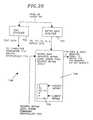
- FIG. 30is a flow diagram of a method for transmitting and recording a program to allow rating level control of viewing of the program according to the present invention
- FIGS. 31 a and 31 bare flow diagrams for a method for allowing rating level control of the viewing of a program according to the present invention.
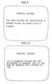
- FIG. 32illustrates the display of text data on a television monitor according to the present invention.
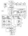
- parental control circuity 40is shown in FIG. 1 for providing parental control of the use of a television receiver.
- the parental control circuitry 40is directly connected to the signal source input line 39 which is attached to parental control circuitry 40 through the tamper proof connector 50 .
- the signal source input line 39may be from one of many typical sources such as an antenna, television cable, or a satellite converter box.
- the signal source input line 39is locked to the parental control circuitry 40 by the tamper proof connector 50 so that the parental control circuitry 40 may not be easily removed from the system and simply bypassed.
- the output of the parental control circuitry 40is sent to cable box 43 , which converts channels for use by the VCR 44 and the television monitor 45 .
- the cable 41 between the parental control circuitry 40 and the cable box 43may also have tamper proof connecters on either end, such as tamper proof connector 52 and tamper proof connector 54 .
- the purpose of the parental control circuitry 40is to allow parents to either enable selected programs for viewing, or to block selected programs. Locating the parental control circuitry 40 between the signal source input line 39 and the cable box 43 allows the enabling or blocking of programs that are purposely scrambled and intended to be unscrambled by the cable box 43 .
- the parental control circuitry 40can be commanded via control keys on the parental control circuitry 40 (not shown) or the remote controller 12 , which is further described below. To communicate with the remote controller 12 , the parental control circuitry 40 has an infrared detector 32 .
- the parental control circuitry 40also has an infrared emitter 46 which can communicate with infrared detector 48 in the cable box 43 .
- infrared detector 48For example, if parental control circuitry 40 is tuned to a particular channel associated with a selected program, then the parental control circuitry 40 can communicate via infrared emitter 46 to switch cable box 43 to the same channel via infrared detector 48 .
- the output of cable box 43is typically channel 3 or channel 4 , and the VCR 44 and the television monitor 45 are typically tuned to the output channel of the cable box 43 .
- FIG. 2is a specific embodiment of parental control circuitry 40 .
- signal source input on line 39is passed through programmable multiple channel filter 60 to form the parental control output on line 41 .
- Programmable multiple channel filter 60is controlled by command controller 36 .
- the command controller 36receives commands from infrared detector 32 and outputs commands to cable box 43 via infrared emitter 46 .
- Command controller 36is coupled to/from the clock 42 and the compressed code decoder 38 , which also has an input from the clock 42 .
- the clock 42 in parental control circuitry 40can be synchronized with a clock in VCR 44 and any other clocks in the parental control system 11 by downloading time encoded as audio tones from telephone 35 to microphone 34 and remote controller 12 , which can then send the time to the various clocks in the system to synchronize them.
- the command controlleralso receives an input from key switch 33 , which has a parental control (PC) position and a normal position.
- the key for key switch 33should be kept by the parent in a secure place. If the key switch is in the normal position then any program can be watched. If the key is in the PC position, then only programs that are enabled can be watched.
- Outputs from command controller 36may include input selection switch 57 and vertical blanking interval decoder 437 , as shown in FIG. 18, when the parental control circuitry is also connected to devices other than the cable loop.
- the parental control circuitry 40may be located inside the television as shown in FIG. 18 or outside the television and somewhere before the input to the television.
- the command controller 36 and compressed code decoder 38can be implemented as shown in FIG. 5 and are described in further detail below. However, before the details of FIG. 5 are described, the programmable multiple channel filter 60 of FIG. 2 and its operation are described.
- the programmable multiple channel filter 60can be implemented as shown in FIG. 3 .
- a userhas specified a number of programs to be blocked from viewing on the television 45 .
- the usercan specify which programs to block by either specifying particular programs to be blocked, or by specifying that all programs on a particular channel be blocked.
- FIG. 3shows a programmable multiple channel filter 60 which can filter multiple channels from the broad band television signal input 39 .
- switch 66is shown as open which indicates that the channel 3 filter 63 will filter channel 3 from the parental control output 41 .
- switch 65 and switch 67are closed allowing the broad band television signal input 39 to bypass channel 2 filter 62 and channel 4 filter 64 .
- channels 2 and 4are not filtered from the parental control output 41 .
- Switches 65 - 71are controlled by switch interface 61 which is in turn controlled by command controller 36 . If a particular program is to be blocked from viewing, then the command controller 36 opens the appropriate switch, for example, switch 66 for channel 3 , at the start of the program and closes the switch 66 at the end of the program. This would block the viewing of that particular program on channel 3 . To perform this function, the command controller needs to know the channel, date, time-of-day and length (CDTL) of the program to be blocked from viewing. This CDTL information can be either input as channel, date, time-of-day and length to the parental control circuitry 40 or can be entered via compressed codes, which are described below, via remote controller 12 .
- CDTLchannel, date, time-of-day and length
- Another method of determining when to block a programis to look for a program identifier in the signal received from the television signal source. If the received program identifier matches the program identifier of a program to be blocked that has been entered in the command controller 36 , then the program is blocked.
- An example of this methodis called VPS, which is a program identification transmitted with the television signal in European broadcasting systems. This technique can also be used to enable programs.
- FIG. 4shows an example frequency spectrum for a broad band television signal that has been filtered by programmable multiple channel filter 60 .
- channels 3 , 6 , and 7have been filtered so that programs in those channels cannot be viewed. Because it is possible with the programmable multiple channel filter 60 to either block the viewing of an entire channel or a particular program, the frequency spectrum of the parental control output 41 will change over time as the command controller 36 sends commands for turning on and off the switches 65 - 71 to the switch interface 61 .
- the remote controller 12shown in FIG. 1 has a number of keys, which include numerical keys 20 , compressed code switch 22 , function keys 24 , program key 26 , and power key 27 .
- the remote controller 12also includes a total parental control key 29 and an enter key 31 .
- the remote controllermay further advantageously include a cursor control having up/down keys 17 and 21 , respectively, right/left keys 19 and 23 , respectively, and an activate key 25 .
- the remote controlleris essentially the same as any other remote controller in function. It is to be noted that the typical keys of remote controllers, such as volume control and channel selection, are not shown on the controller of FIG. 1, but would ordinarily be present.
- the total parental control key 29 and enter key 31are used when selecting programs that are to be blocked or enabled for viewing on the television.
- the enter key 31is used when entering the user's identification code that permits programming of the parental control circuitry to set up the programs to be blocked or enabled for viewing on the television receiver.
- the compressed code switch 22is provided to allow the user to lock the remote controller 12 in the compressed code mode while using a compressed code, which is encoded CDTL information.
- the compressed codesallow easy selection of a program to be enabled or blocked under parental control.
- the remote controller 12also can have a microphone 34 , which can be used together with telephone 35 , to download encoded CDTL information or compressed codes as well as other information such as time and IR codes for the particular devices.
- the compressed codes for programs that are to be enabled for viewing or blocked from viewingare entered via audio tones from telephone 35 .
- the compressed codes or program identifiers from a preselected list of violent programsare downloaded via telephone from a central data base. The parent calls the data base and then holds the television receiver 35 , near the remote controller microphone 34 .
- the received compressed codesare then communicated from the remote controller 12 to command controller 36 .
- the violent programmay be coded and a printed television guide and the parent may enter the compressed code for the selected programs by using the keypad of the remote 12 .
- the command controller 36includes a microprocessor 80 for overall control and for performing the parental control functions, a read only memory 82 for program storage, a random access memory (RAM) 84 , and input/output circuitry 86 .
- This input/output circuitry 86is adapted to receive commands from the infrared detector 32 and the key switch 33 .
- the input/outputhas output interfaces to infrared emitter 46 , and, when appropriate, to input selection switch 57 and vertical blanking interval decoder 437 , the latter two of which are shown in FIG. 18 .
- the input/output circuitry 86has a bidirectional interface to clock 42 .
- the random access memory 84includes a section for the parental control identification code and a section of stack memory for storing the channels, dates, times-of-day, and lengths for programs selected to be enabled for viewing or, alternatively in the case of exclusion, the channels, dates, times-of-day, and lengths for programs selected to be blocked from viewing. Either the ID number section, or the stack memory may be separate from RAM 84 .
- the compressed codewhich are encoded CDTL information, may be advantageously used to simplify the parental control operation of the television.
- FIG. 5One implementation of the compressed code decoder 38 is shown in FIG. 5.
- a microcontroller 90 with a random access memory 92 and a read only memory 94has interfaces to microprocessor 80 .
- the encoded CDTLis sent to microcontroller 90 , which decodes the compressed code and returns CDTL information to microprocessor 80 .
- a compressed code decoder 38is included in the parental control circuitry 40 of FIG. 1 and is further shown in FIGS. 2, 13 , and 16 . If the command controller 36 determines that a compressed code has been received, then the compressed code will be sent to the compressed code decoder 38 for decoding.
- the compressed code decoder 38converts the compressed code into channel, date, time and length (CDTL) information which is stored in RAM 84 and used by the command controller 36 to control the enabling and clocking of particular programs.
- the compressed code encoding and decodingcan be made a function of the time read from the clock 42 . This makes it very difficult for the key and therefore the coding technique to be duplicated or copied. It is also possible to have the decoding and encoding techniques dependent on any other predetermined or preprogrammable algorithm.
- the clock 42is also used for the timing of the operation of the command controller 36 .
- the command controller 36controls the parental control circuitry 40 to block or enable programs going to the cable box 43 .
- the operation of the parental control device 40 of FIG. 1may be better understood by reference to the flow chart set forth in FIG. 6 .
- the TVis turned on at step 300 , and any other ancillary apparatus, such as parental control circuitry 40 in FIG. 1, is also turned on. If the key lock 33 is in the position for normal TV viewing, then the normal viewing of step 301 will be available. After completion of viewing, the TV is shut off (step 302 ). If the key lock 33 is in the parental control position, then upon turning on the TV, the selections that are enabled or blocked for viewing will be displayed on the screen as shown in step 303 . A representative display of programs to be enabled in step 303 is shown in FIG. 7. A similar display is used to display blocked programs.
- the user of the apparatusmay then select one of the programs that is enabled for viewing in step 304 and, upon completion of viewing, the TV is then shut off in step 305 . If the programs to be blocked or enabled are to be modified, then the total parental control key, such as key 29 in FIG. 1, is pushed in step 307 .
- the pushing of the total parental control key 29will cause a message to appear on the screen of the TV such as the one shown in FIG. 8 wherein the user is requested to enter his or her identification (ID) code or number.
- IDidentification
- the userenters his or her ID in step 309 by using the numbers of the key pad 20 , for example, as shown in the remote controller of FIG. 1 .
- the authorized user ID codeswill have been previously stored in the parental control ID section of the RAM 84 , as illustrated in FIG. 3.
- a typical user IDmight be 6823 which, when entered, is compared in the verify step 310 under the control of the microprocessor 80 with the authorized parental control IDs stored in the RAM 84 .
- the ID code numberis entered by pressing keys numbered 6 , 8 , 2 and 3 and then the enter key 31 . If the ID number that is entered is not an authorized number stored in RAM 84 , then the user will be advised in step 311 by a message, such as the message of FIG. 9, displayed on the TV screen that the ID number is incorrect and the entry of another ID number will be requested. Steps 309 and 310 will, again, take place upon the entry of the new ID number and, if this ID number is again incorrect, the user will again be advised in step 311 . Upon the entry of a number of incorrect ID numbers, such as 3, which are monitored in step 312 , then the user will be advised in step 313 by a message such as the one shown in FIG. 10 that the ID numbers that have been entered are not authorized ID numbers and that the TV will be disabled for a period of time. The period of time may, for example, be 30 minutes or one hour or whatever may be selected during set up by the authorized user of the equipment.
- step 315a menu will be displayed on the TV screen, such as shown in FIG. 11 .
- the menu displayed in step 315 as shown in FIG. 11has choices for enabling programs, blocking programs, and enabling V-block, which is a choice that allows the blocking of scenes in programs or entire programs that have objectionable violence, nudity, or language.
- One or more of the possible selections set forth in the menu of FIG. 11may be selected in step 316 .
- the usermay also select entry 6 on the menu to override the parental control operation by pushing number 6 on, for example, the remote controller 12 of FIG. 1, for normal TV viewing. This will cause the override of step 317 to permit normal TV viewing (step 318 ) after which the TV will be shut off in step 319 or the menu of FIG. 11 may again be displayed in step 320 by pushing the MENU key 37 shown in FIG. 1 .
- buttons 1With the menu displayed on the screen of the television in step 315 or 320 , the user need only push one of the numbered keys on key pad 20 to set up the mode for selecting one of the possible selections as shown in the menu of FIG. 11 .
- the pushing of button 1will permit the selection of programs to be enabled, as illustrated in FIG. 7 .
- button key 1Upon pushing button key 1 , for example, (step 321 ), the previous selections that have been made will be displayed along with instructions for making deletions or additional selections.
- step 322If programs are to be deleted in step 322 , the user activates the cursor by pressing button 25 (FIG. 1 ), and then moves the cursor on the TV screen displaying the available programs, e.g., as shown in FIG. 7, by use of the up/down keys 17 and 21 and the right/left keys 19 and 23 to the program that is to be deleted. With the cursor highlighting the program to be deleted, the enter key 31 is depressed to complete the deletion of the program from programs that may be viewed. In step 322 , programs may, alternatively, be deleted by entering a compressed code for a program, as shown in FIG. 7 .
- the compressed codes that appear with the programs listed in the printed TV schedulesmay advantageously be employed.
- the useron deciding which of the programs listed in the TV schedule to make available for viewing, enters the compressed code for each of these programs by using the keypad 20 on the apparatus or on the remote controller, as shown in FIG. 1, and the enter key 31 .
- the TV schedulemay also be made available on a floppy disk, as disclosed in U.S. Patent application Ser. No. 07/882,291 filed May 13, 1992 and incorporated herein by this reference as though set forth in full.
- a floppy disk drivemay be incorporated into the parental control circuitry, the VCR, or the television for reading the TV schedule and displaying same on the screen of the TV.
- programs to be addedmay be selected by use of the cursor keys shown in FIG. 1 or by entry of the compressed code that is listed in the TV schedule retrieved from the floppy disk.
- the TV schedulemay be available as part of the TV broadcast signal in the vertical blanking interval of the TV signal or as the video program.
- the schedule informationmay be retrieved from the TV broadcast signal by a vertical blanking interval decoder 437 , as shown in FIGS. 18 and 19 and displayed on the TV monitor 442 of FIGS. 18 and 19, for example.
- the programs to be addedmay be selected by use of the cursor keys as shown in FIG. 1, or by entry of the compressed code as described above.
- Steps 321 ′, 322 ′, and 323 ′operate in an analogous manner to steps 321 , 322 , and 323 .
- the V-block modemay be selected by pushing button 3 when the menu is being displayed on the TV screen in step 316 .
- the V-block modeenables the automatic blocking of programs or scenes in programs that have objectionable violence, nudity, or language. The V-block operation is described further below.
- each selection to be addedis stored in RAM 84 and at the completion of the selection process transferred to the stack memory portions of RAM 84 for storage in temporal order.
- the menu key 37is depressed to return to step 315 for display of the menu shown in FIG. 11 .
- the key 7may be depressed while the menu is being displayed to compare the selections that have been made for possible inconsistencies, which is done in step 354 . For example, if programs have been both enabled and blocked this will be noted as an inconsistency. If there are no inconsistencies, then the microprocessor 80 causes the selections to be stored in step 356 in the stack memory portion of the RAM 84 .
- step 354If inconsistencies do exist in step 354 , then the program, channel, date, or time that is to be deleted to avoid the inconsistency is selected in step 355 by depressing the appropriate key 1 , 2 or 4 and going through the delete step 322 or 322 ′. Once there are no inconsistencies in the selections and the selections are stored in the stack memory portion of RAM 84 , then the TV is shut off in step 357 .
- FIG. 12Another specific embodiment of the parental control circuitry 40 is shown in FIG. 12 .
- Most of the elements of FIG. 12are the same as those shown in FIG. 2 so an explanation of those will not be repeated.
- tunable channel jammer 400which is imposed between signal source input line 39 and parental control output line 41 .
- the purpose of tunable channel jammer 400is to block the viewing of particular channels, or programs. Implementing the programmable multiple channel filter of FIG. 3 might be fairly expensive, because each channel filter would have to be fairly precise in order to not interfere with adjacent channels and the number of components involved would result in a high cost. Rather than filtering a channel as in FIG. 3, tunable channel jammer 400 instead has the purpose of jamming a channel or multiple channels.
- a channelis selected to be blocked from viewing, then the jamming on that channel can be continuous. If particular programs have been selected to be blocked from viewing, then the respective channels for those programs will be jammed on that date starting with the time of day for that program and end after the program has ended. The start and end time for the programs can be attained from the CDTL information in the G codes.
- FIG. 13shows an apparatus for implementing tunable channel jammer 400 .
- a narrow band noise source 402is mixed with a tunable frequency generator 404 in mixer 406 and then combined with signal source input line 39 in combiner 408 to produce the parental control output on line 41 .
- the tunable frequency generator 404would be tuned to place the narrow band noise inside the channel to be jammed. Multiple channels can be jammed by time sharing the circuity of FIG. 13 . For example, if channels, 2 , 3 , 5 , and 10 are to be jammed at the same time then the tunable frequency generator 404 would be tuned to each of those channels for a set period of time and then would skip to the next channel to be jammed and so on. If the duty cycle of the jamming on any particular channel is high enough, then the channel will be unwatchable. By time sharing the apparatus in this manner considerable costs can be saved.
- a low frequency generator 402is supplied.
- tunable frequency generator 404is used to place the low frequency within the channel to be jammed. Tests have shown that a noise generator with a 1 kilohertz bandwidth centered at 55 megahertz is sufficient to block the viewing of channel 2 .
- the circuity of FIG. 13may be time shared between as many as 10 channels at a time which results in a 10 percent jamming duty cycle on any particular channel.
- FIG. 14is an illustration of a frequency spectrum showing jamming occurring in channels 2 , 4 , and 7 .
- FIG. 15is a specific implementation of parental control circuitry 40 which allows particular channels or programs to be enabled for viewing on a television. Again, most of the elements of FIG. 15 are similar to those in FIG. 2, however, tunable channel selector 420 is different and has the purpose of enabling certain channels or programs for viewing.
- FIG. 16shows an implementation of tunable channel selector 420 .
- the signal on signal source input line 39is frequency down converted by mixing this signal with the output of tunable local oscillator 422 in frequency down-converter 424 .
- the output of frequency down-converter 424is then filtered by intermediate frequency filter 426 to pass only the channel to be enabled for viewing.
- This channelis then frequency up converted by frequency up-converter 428 , which mixes the output of intermediate frequency filter 426 with the output of tunable local oscillator 422 .
- the amount of frequency down conversion in frequency down-converter 424is equal to the amount of frequency up conversion in frequency up-converter 428 .
- the tunable local oscillator 422is the same for frequency down-converter 424 and frequency up-converter 428 .
- FIG. 17illustrates the frequency spectrum at signal source input line 39 , the frequency down-converter 424 output, the intermediate frequency filter 426 output, and the output on parental control output line 41 of FIG. 16 .
- the resultis that on parental control output line 41 only the selected channel is remaining which is channel 10 in FIG. 17 . Since at any one time only one channel is enabled for viewing, the command controller 36 must command the cable box 43 to tune itself to the proper channel. This is done by communicating through infrared emitter 46 to infrared detector 48 on cable box 43 .
- a parental control television 430is shown in FIG. 18 .
- the parental control television 430has parental control circuitry 40 incorporated into it.
- the parental control circuitry 40 inside the parental control television 430can be implemented as previously discussed to either block certain programs and channels from viewing or enable certain programs and channels for viewing.
- parental control circuitry 40can be implemented as shown in FIG. 2, FIG. 12, or FIG. 15 .
- the signal source input line 39is connected to the parental control television 430 by a tamper proof connector 432 to prevent tampering.
- the cable box 43 and VCR 44can be located outside of the parental control television 430 .
- a scene V-Block indication 449can be put into one of the vertical blanking intervals lines, as shown in FIG. 21, which is described below along with FIGS. 19 to 24 .
- the vertical blanking linesare then decoded by vertical blanking interval decoder 437 . If vertical blanking interval decoder 437 detects a scene V-block indication 449 in the vertical blanking interval lines, and if the V-block mode has been enabled by parental control circuitry 40 via line 441 , then the vertical blanking interval decoder 437 will open the V-block switch 439 . This will block the offending scene from the television monitor 442 .
- the V-Block featurewill also operate to block offending scenes from any programs played on the VCR which have a scene V-Block indication in the vertical blanking interval. This provides parental control for programs that are recorded with a scene V-block indication.
- V-Block approachdoes not provide for control by rating levels, such as PG-13, R, X etc.
- Control by rating levelis desirable to give the parent or viewer the ability to select by level rather than on or off approach as provided by V-block.
- data packets indicative of a particular rating levelis associated with a program segment and is transmitted with the segment.
- the segmentmay be as short as one scene in a movie or television program or longer.
- Each segment that has a rating level lower than a standard level, such as G (general audience) for moviesmay be rated and a data packet included at the beginning of the segment.
- Video images in a cathode ray tube (CRT) type-video deviceare generated by scanning a beam along a predefined pattern of lines across a screen. Each time all the lines are scanned, a frame is said to have been produced. In one implementation, such as used in the United States, a frame is scanned 30 times per second.
- Each television framecomprises 525 lines which are divided into two separate fields, referred to as field 1 (“odd field”) and field 2 (“even field”), of 262.5 lines each. Accordingly, these even and odd fields are transmitted alternately at 60 Hz.
- VBIvertical blanking interval
- the VBIis used for conveying auxiliary information from a television network or station to an audience.
- closed caption data associated with the television programare transmitted as encoded composite data signals in VBI line 21 , field 1 of the standard NTSC video signal, as shown in FIG. 21 .
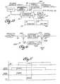
- FIG. 20is a functional block diagram of a data transmission system.
- a network head end 10001transmits a composite television signal containing inserted information in a portion thereof, typically the vertical blanking interval, to a satellite 10002 which rebroadcasts the same to a local affiliate 10003 .
- the affiliate 10003may further insert data into the vertical blanking interval of the received television signal and transmit the same to a local cable head end 10004 .
- the cable head end 10004receives television signals from a plurality of sources (including satellites) and may further insert data into the vertical blanking interval of any of the television signals.
- the network head endhas a video tape recorder (VTR) 10006 for providing a program signal to an inserter 10007 .
- VTRvideo tape recorder
- a controller 10008also at the head end controls the scheduling of loading tapes from a cart (a machine with a plurality of video tape cassettes which are moved by a robotic arm from a storage location and inserted into a video tape recorder and vice versa). Furthermore, the controller 10008 controls the lighting of stages during live broadcasts, such as news broadcasts.
- the controller 10008is typically a microprocessor based system.
- a traffic computer 10009controls the exact timing of playing individual segments of video tapes and inserting commercials therebetween as well as switching between different programs. Some network head ends have both a traffic computer 10009 and a controller 10008 .
- the controller 10008provides data and commands to the inserter 10007 .
- the traffic computer 10009provides data and commands to the controller if present. Otherwise, the traffic computer 10009 provides these signals directly to the inserter 10007 .
- the inserter 10007inserts data into the vertical blanking interval of the composite television signal, as will be described below, and provides the television signal to a transmitter 10010 which in turn provides the television signal on a microwave carrier to a satellite dish 10011 for transmission to the satellite 10002 .
- the satellite 10002retransmits the received signal, which is received by a satellite dish 10012 at the affiliate 10003 .
- the dishprovides the signal to a station inserter 10013 at the local affiliate 10003 .
- the affiliatemay also insert data into the composite television signal as will be described below.
- the television signalis then provided to a transmitter 10014 and then to a transmitting antenna 10015 .
- a local cable operator 10004has a plurality of satellite dishes 10016 and antennas 10017 for receiving signals from a plurality of networks 10001 and affiliates 10003 .
- the received signal from each of the dishes 10016 and antennas 10017is provided to a respective input of a multi-channel inserter 10018 , which can input data into the vertical blanking interval of a received signal.
- the multi-channel output from the inserter 10018is amplified in an amplifier 10019 and provided over a cable 10020 to individual receivers 10005 .
- the receivers 10005could receive broadcast information via antennas or satellite receivers.
- Each receiver 10005includes a VBI decoder, which can include a VBI slicer and closed caption decoder, that scans VBI lines 10 - 21 of both fields 1 and 2 .
- VBI decodercan include a VBI slicer and closed caption decoder, that scans VBI lines 10 - 21 of both fields 1 and 2 .
- lines 22 - 24lines 22 - 24 .
- Lines 1 through 9are typically used for vertical synchronization and equalization and, thus, are not used to transmit data.
- Closed captioning and text mode dataare generally transmitted on VBI line 21 , field 1 of the standard NTSC video signal, at a rate of 2 bytes for each VBI line 21 , field 1 , as shown by closed caption data 612 in FIG. 21 .
- the text mode fieldsfill the entire screen with text.
- the default modeis an open ended mode in which the page is first filled up and then scrolled up.
- the individual recipient of such datahas no control over the data.
- Extended data services (EDS) datacan be transmitted on VBI line 21 , field 2 , as shown by EDS data 616 in FIG. 21, at a rate of 2 bytes per VBI line 21 , field 2 .
- the closed caption data wave formhas a clock run-in followed by a frame code, followed by the data.
- the coding of the datais non-return-to-zero (NRZ) 7 bit odd parity.
- EIA-608Under the extended data services (EDS) proposed in the Recommended Practice for Line 21 Data Service, Electronics Industries Association, EIA-608 (drafts Oct. 12, 1992 and Jun. 17, 1993) (hereinafter referred to as “EIA-608” standard′′), the subject matter of which is incorporated herein by reference, additional data is provided in line 21, field 2 of the vertical blanking interval.
- EIS-608extended data services
- This recommended practiceincludes two closed captioning fields, two text mode fields and the extended data services.
- the extended dataincludes, among other information, program name, program length, length into show, channel number, network affiliation, station call letters, UCT (universal coordinated time) time, time zone, and daylight savings time usage.
- the networkUpstream at the network, the network inserts the program name, the length of the show, the length into the show, the network affiliation, and the UCT time. Downstream at the affiliate, the affiliate inserts the channel number, the time zone, the daylight savings time usage and program names. The network inserts the data that does not differ for different affiliates.
- the data inserted into the television signal by the various insertersincludes closed captioning data and EDS data.
- the inserted datacan include rating data packets, such as PG start data and PG end data, and text 614 , as shown in FIG. 21 .
- rating data packetssuch as PG start data and PG end data, and text 614 , as shown in FIG. 21 .
- this datais inserted into a program video segment.
- the datacan be inserted into either or both fields in any VBI line between 10 and 20.
- the datacan be inserted into line 20 of field 2 , as shown by the data 614 in FIG. 21 .
- the datamay be inserted into the VBI at the closed caption rate (1X format) or at two times the closed caption rate (2X format), which is further explained below.
- the datamay be manually entered from a local terminal 10021 .
- the local terminal 10021may be used to pre-build, recall, or edit messages.
- the terminal 10021typically includes a computer.
- a modem 10022may be used to provide data to the inserter 10007 .
- the datamay be provided manually or automatically from remote sites, such as a television program guide publisher or the network head end.
- the output of the inserter 10007is a composite television signal with the data inserted. This system processes both teletext data (which is not related to the program) and auxiliary information (which is related to the program).
- the timing of video signals in NTSC formatis well known in the art.
- the vertical blanking intervalis the time between the flyback from the bottom of the screen to the top of the screen.
- the horizontal synchronization pulsesare still provided during the VBI.
- the standard data transmission rateis defined in the EIA-608 standard.
- the horizontal synchronization pulse 620is followed by color burst signals 622 .
- a clock run-in cycle 624follows the color burst which in turn is followed by a frame code 626 .
- the clock run-inis “10101010101.”
- the frame codeis “01000011.”
- Two data bytes 628 and 630are transmitted in each VBI line. Each byte is 8 bits including a parity bit. This format is referred to as the standard data rate format (or 1X format).
- Each byte in the VBI lineis arranged with the least significant byte first. The last bit is used as parity for error checking
- Each byte of the transmitted datais parity checked upon receipt.
- the 1X formatis the format used to transmit closed captions in VBI line 21 field 1 , as shown by closed caption data 612 in FIG. 21 . It is also the format used to transmit EDS data in VBI line 21 field 2 , as shown by EDS data 616 in FIG. 21 .
- An accelerated data format (2X format) as shown in FIG. 22 buses a bit rate twice that of the 1X format to thereby provide 4 bytes per VBI line.
- the clock run-in 644is the bit sequence “10101010.”
- the frame code 646is “10011101101.”
- Four data bytes 648 , 650 , 652 and 654are transmitted each VBI line.
- the 2X formatcan be used to transmit data 614 in FIG. 21 .
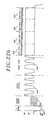
- FIG. 23is an illustration of a video signal having rating data incorporated into the video signal 660 to allowing rating level control of the viewing of a program.
- G-rated video 662is being received and then at a later time a PG-13 rating start data 664 is embedded in the vertical blanking interval.
- the PG-13 rating start data 664is followed by a PG-13 rated video 666 , which is then followed by a PG-13 end data 668 which is embedded in the vertical blanking interval.
- PG-13 rating end data 668After the PG-13 rating end data 668 , a G-rated video 670 portion continues.
- the 20can be used to insert the rating start signal data, rating end signal data, and text into the vertical blanking interval, as shown in FIG. 21 .
- the PG-13 rating start data and PG-13 rating end dataare used to mark the beginning of the PG-13 rated video segment and the end of the PG-13 rated video segment.
- the purpose of the inserted PG-13 rating start data, PG-13 rating end data and text in the vertical blanking interval,is to allow a user such as a parent, rating level control of the viewing of the program contained in the video signal.
- the PG-13 rating start datais extracted from the vertical blanking interval and used to block the following PG-13 rated video segment data 666 from the television monitor.
- the text data 667 embedded in the vertical blanking intervalis extracted from the vertical blanking interval.
- the television screenis switched to a blue screen.
- the text data 667is displayed.
- the textcontains the description of what is happening in the plot during that PG-13 rated video segment in a nonviolent style. For example, a bloody fight might be blocked and then the text of FIG. 32 displayed (e.g. A and B fight. B does not survive.)
- the text data 667remains on the television monitor until the PG-13 rating end data 668 data is extracted from the vertical blanking interval. Then the G-rated video 670 appears on the television screen.
- the text that is extracted from the vertical blanking intervalis sent to an audio synthesizer which is used to voice the text data. This is especially useful for children who cannot yet read.
- FIG. 24is another illustration of a video signal that contains data for allowing rating level control of television viewing.
- G-rated video 682is followed by PG-13 rating start 684 , which in turn is followed by PG-13 rated video segment 686 .
- PG-13 rating end data 688occurs at the end of the PG-13 rated video segment.
- R rating start data 690which is embedded in the vertical blanking interval occurs.
- R rating end data 694is embedded in the vertical blanking interval.
- G-rated video 696 portioncontinues.
- Text 687 and text 693are embedded in the vertical blanking interval during the PG-13 rated video segment and the R rated video segment, respectively.
- the userwishes to allow viewing of PG-13 rated video.
- the usercan enter data for the desired rating level which in this case would be PG-13.
- the apparatuswould play G rated video 682 and continue playing PG-13 rated video segment 686 .
- R rating start data 690the apparatus blocks the R rated video segment from the television screen and instead displays text 693 after it is extracted from the vertical blanking interval.
- R rating end data 694is detected, the display of G rated video 696 portion continues. This example illustrates that the apparatus does not always block a marked video segment. The blocking of a rated video segment depends on the desired rating level entered by the user.
- FIG. 23 and FIG. 24show video signals that can be transmitted on the air or by land based broadcast or satellite broadcast or over a cable, (including fiber optics).
- FIG. 25illustrates an apparatus for allowing rating level control of the viewing of a program.
- a television signal source 702provides the video signal and can be an antenna for receiving over the air video signals or a cable for receiving cable television.
- a tuner 704tunes the apparatus for receiving the video signal.
- a vertical blanking interval slicer 702is coupled to the output of tuner 704 and has outputs to a rating and text decoder 708 , EDS decoder 710 , and closed-captioned decoder 712 .
- the EDS decoder 710 and the closed captioned decode 712are for decoding data sent via extended data services or closed captioned services, as described above.
- the rating and text decoder 708has the purpose of extracting the rating data and the text data from the vertical blanking interval to allow rating level control of the viewing of a program.
- the rating datais decoded by the rating and text decoder 708 and is used to send a video blanking signal on line 716 to switch 718 under the control of command controller 724 .
- the switch 718decouples the output of tuner 704 from the television monitor 722 to preclude display of the relevant program segment.
- Text data in the vertical blanking intervalas described in connection with FIGS. 23 and 24, is decoded by rating and text decoder 708 and sent to character generator 714 and audio synthesizer 715 .
- the output of character generator 714 and audio synthesizer 715are sent to adder 720 which become the characters and the audio sent to the television monitor 722 .
- a desired rating levelis sent to the rating and text decoder 708 from command controller 724 which has a memory 726 which can store the entered desired rating level 728 .
- the desired rating levelcan be entered either via keypad 731 or via remote controller 732 .
- An IR transmitter 734 in the remote controller 732communicates the desired rating levels to the command controller via IR receiver 730 .
- FIG. 26is a more detailed schematic of rating and text decoder 708 .
- the input from VBI slicer 706is sent to text decoder 752 and rating data detector 740 .
- the output of the text decoder 752is the text data which is sent to character generator 714 and to audio synthesizer 715 .
- the output of the rating data detector 740consists of, for example, PG, PG-13, R, and X rating data.
- the rating datacan be inserted at the beginning to mark the beginning of a rated video segment and at the end of a video segment to mark the end of the video segment.
- the rating datacould be sent continuously or near continuously during the rated video segment and embedded in the vertical blanking interval to mark the video segment for control of viewing of the rated video segment.
- the rating data from rating data detector 740is sent to device 748 .
- the device 748has the purpose of determining from the extracted rating data and the entered desired rating level that is sent from the command controller 724 , whether or not to block a received audio and video signal from a television monitor.
- the output of device 748is sent to switch 718 .
- One way of implementing device 748is to provide a table 750 which ranks the order of the rating levels from the highest rating G to the lowest rating X.
- the rating hierarchyis G, PG, PG-13, R, and X.
- the userenters a desired rating level and the device 748 detects whether the rating data indicates a rating level that is lower then the desired rating level.
- the desired rating levelis PG-13 and the rating data indicates a video segment that has a rating level of R then the video segment has a rating level that is lower than the desired rating level.
- a video and audio blocking signalis sent on line 716 to switch 718 and opens switch 718 to block the video and audio of the program segment from the television monitor.
- the desired rating levelis PG-13 and the rating data indicates a rating level of PG, then because the rating data has a higher rating in table 750 than PG-13, the video and audio blocking signal does not open switch 718 and the video and audio signal is sent to the television monitor thereby allowing viewing of the PG material.
- FIG. 27shows a G rated video 760 at the start of the tape followed by a PG-13 start data 762 in the vertical blanking interval followed by a PG-13 rated video segment 764 .
- Text data 765is embedded in the vertical blanking interval during the PG-13 rated video segment 764 .
- a PG-13 end data 766is embedded in the vertical blanking interval followed by a G rated video segment 768 .
- FIG. 28shows a portion of a tape with two rated video segments, a PG-13 rated video segment and an R rated video segment 780 .
- Eachhas a start and an end rating data ( 772 , 776 and 778 , 783 , for example) embedded in the VBI and text in the VBI such as text 775 and 781 .
- the portion shown in FIG. 28starts with G rated video 770 and ends in G rated video 782 .
- a tape that is recorded in the manner shown in FIGS. 27 and 28can be played on a video cassette recorder such as video cassette recorder 800 shown in FIG. 29 .
- the VCR 800which is similar to the VCR disclosed in FIG. 1 of the above referenced application Ser. No. 08/176,852, contains a vertical blanking interval decoder 860 that decodes the vertical blanking interval from video signals read from the tape 842 by video logic 807 or received from a television signal source through tuner 861 .
- the VBI decoder 860is coupled to VCR control logic 821 .
- the VBI decoder 860 and the VCR control logic 821perform the functions of vertical blanking interval slicer 706 and rating data and text data decoder 708 shown in FIG. 25.
- a video and audio blocking signal on line 873controls switch 874 in the same manner as the video and audio blocking signal on line 716 controls switch 718 .
- the VCR control logicdecodes the text data and sends the text data to character generator 870 and audio synthesizer 871 which have outputs that communicate to adder 876 that inserts the characters or the voiced text from the audio synthesizer as the signal sent to the television monitor.
- a desired rating levelcan be entered via remote controller 880 via IR transmitter 882 and remote signal receiver 872 .
- the desired rating levelcan also be entered via keypad 877 into VCR control logic 821 or by a similar keypad remote 880 .
- the VCR 800can also contain a tuner 861 and can record or apply to the television monitor a program from a television signal source.
- the transmitted programcan be recorded onto the tape 842 and then when the program is later played the feature of the VCR that allows rating level control of the viewing of a program can be used.
- the operation of the feature for allowing rating controlis the same for VCR 800 as for the apparatus described in FIG. 25 .
- FIG. 30is a flow diagram for a method for allowing rating level control of the viewing of a program.
- rating dataindicating the rating level of each program video segment is inserted into the program video segments.
- text datarepresenting the plot of the video segment is inserted into the program video segment.
- the rating data and the text datacan be inserted into the vertical blanking interval of the program video segments.
- the videois recorded along with the rating data and the text data in the vertical blanking interval.
- step 906the video is transmitted along with the rating data and the text data inserted in the program video segments.
- the transmitted videois recorded along with the rating data and the text data onto a tape.
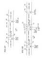
- FIG. 31 a and FIG. 31 bare flow diagrams of a method for allowing rating level control of a program.
- rating datais extracted from the beginning of a program video segment.
- the rating dataindicates the rating level of the programmed video segment.
- the extracted rating datais compared with a desired rating level.
- step 914it is determined whether the extracted rating data has a lower rating than the desired rating levels. If the rating data is equal to or higher than the desired rating level then the method returns to step 910 . If the extracted rating data has a lower rating level than the desired rating level, then step 916 is performed. In step 916 the video and audio are blocked from the television monitor. Then in step 918 text data is extracted from the program video segment.
- the text datais used to generate characters for the text in step 920 and audio in step 921 .
- step 922the characters are displayed on a television monitor.
- audiois synthesized for voicing the text, and in step 923 the audio is applied to the television monitor.
- step 924(shown in FIG. 31 b ) it is determined whether an end rating data has been extracted from the video signal. If not, then the text displayed in step 922 , and audio applied in step 923 continues.
- FIG. 32illustrates an example text display. If the end rating data is extracted from the video signal in step 924 then in step 926 the text and audio is discontinued and the video and audio signal of the programs are unblocked from the television monitor and the program is again available for viewing.
Landscapes
- Engineering & Computer Science (AREA)
- Signal Processing (AREA)
- Multimedia (AREA)
- Databases & Information Systems (AREA)
- Human Computer Interaction (AREA)
- Computer Security & Cryptography (AREA)
- Two-Way Televisions, Distribution Of Moving Picture Or The Like (AREA)
Abstract
Description
Claims (21)
Priority Applications (1)
| Application Number | Priority Date | Filing Date | Title |
|---|---|---|---|
| US09/546,116US6226793B1 (en) | 1995-02-14 | 2000-04-10 | Apparatus and method for allowing rating level control of the viewing of a program |
Applications Claiming Priority (3)
| Application Number | Priority Date | Filing Date | Title |
|---|---|---|---|
| US38802595A | 1995-02-14 | 1995-02-14 | |
| US69829696A | 1996-08-15 | 1996-08-15 | |
| US09/546,116US6226793B1 (en) | 1995-02-14 | 2000-04-10 | Apparatus and method for allowing rating level control of the viewing of a program |
Related Parent Applications (1)
| Application Number | Title | Priority Date | Filing Date |
|---|---|---|---|
| US69829696AContinuation | 1995-02-14 | 1996-08-15 |
Publications (1)
| Publication Number | Publication Date |
|---|---|
| US6226793B1true US6226793B1 (en) | 2001-05-01 |
Family
ID=23532319
Family Applications (1)
| Application Number | Title | Priority Date | Filing Date |
|---|---|---|---|
| US09/546,116Expired - LifetimeUS6226793B1 (en) | 1995-02-14 | 2000-04-10 | Apparatus and method for allowing rating level control of the viewing of a program |
Country Status (3)
| Country | Link |
|---|---|
| US (1) | US6226793B1 (en) |
| AU (1) | AU5132796A (en) |
| WO (1) | WO1996025821A1 (en) |
Cited By (74)
| Publication number | Priority date | Publication date | Assignee | Title |
|---|---|---|---|---|
| US20010039657A1 (en)* | 2000-04-28 | 2001-11-08 | Tvmentor, Inc. | Methods, systems and devices for selectively presenting and sorting data content |
| US20010054179A1 (en)* | 2000-05-31 | 2001-12-20 | Koichi Nakamura | Broadcast program receiving apparatus and control method thereof |
| US20020057286A1 (en)* | 2000-08-25 | 2002-05-16 | Markel Steven O. | Device independent video enhancement scripting language |
| US20020059629A1 (en)* | 2000-08-21 | 2002-05-16 | Markel Steven O. | Detection and recognition of data receiver to facilitate proper transmission of enhanced data |
| US20020065678A1 (en)* | 2000-08-25 | 2002-05-30 | Steven Peliotis | iSelect video |
| US20020073421A1 (en)* | 1999-12-10 | 2002-06-13 | Gutman Levitan | System for targeted advertisement, personal editing and parental control in a television network |
| US20020120929A1 (en)* | 2001-02-28 | 2002-08-29 | Schwalb Eddie M. | Method and system for mass customization of digital television broadcasts |
| US20020120931A1 (en)* | 2001-02-20 | 2002-08-29 | Thomas Huber | Content based video selection |
| WO2002089473A1 (en)* | 2001-05-02 | 2002-11-07 | Koninklijke Philips Electronics N.V. | Alternative video program display control system |
| WO2002089482A1 (en)* | 2001-05-02 | 2002-11-07 | Koninklijke Philips Electronics N.V. | Television access control system |
| US20030009766A1 (en)* | 2001-07-06 | 2003-01-09 | Koninklijke Philips Electronics N.V. | Person-to-person scheduling and notification of automatic program recording for personalized television |
| US20030103627A1 (en)* | 2001-12-03 | 2003-06-05 | Nierzwick Mark Alan | Method and apparatus for providing parental control |
| US20030107470A1 (en)* | 1997-10-27 | 2003-06-12 | Darren Kady | Locking device for electronic equipment |
| US6636607B1 (en)* | 1998-10-08 | 2003-10-21 | Ati International Srl | Method and apparatus for controlling display of content signals |
| US20040006767A1 (en)* | 2002-07-02 | 2004-01-08 | Robson Gary D. | System, method, and computer program product for selective filtering of objectionable content from a program |
| US6684240B1 (en)* | 1999-12-15 | 2004-01-27 | Gateway, Inc. | Method of setting parental lock levels based on example content |
| WO2003073744A3 (en)* | 2002-02-26 | 2004-02-26 | Kevin S Martin | Apparatus and method for a real time movie editing device |
| WO2004034701A1 (en)* | 2002-10-10 | 2004-04-22 | Thomson Licensing S.A. | Method for the uninterrupted display of television programs with suppressed program segments |
| US6785901B1 (en)* | 2000-05-19 | 2004-08-31 | Webtv Networks, Inc. | Altering locks on programming content |
| US20040187160A1 (en)* | 2003-03-17 | 2004-09-23 | Qwest Communications International Inc. | Methods and systems for providing video on demand |
| WO2004095797A1 (en)* | 2003-04-24 | 2004-11-04 | Koninklijke Philips Electronics N.V. | Class-based content transfer between devices |
| US20050102701A1 (en)* | 2003-11-12 | 2005-05-12 | Lin Charlie K. | Attention parental switch system of video/audio device |
| US20050151882A1 (en)* | 2003-12-17 | 2005-07-14 | Donato Davide S. | Controlling viewing distance to a television receiver |
| US7089576B1 (en)* | 1999-12-30 | 2006-08-08 | Thomson Licensing | Ratings control system with temporary override capability and conflict resolution feature |
| US20060288366A1 (en)* | 1998-07-07 | 2006-12-21 | Boylan Peter C Iii | Interactive television program guide system with local advertisements |
| US20060294539A1 (en)* | 2005-06-27 | 2006-12-28 | Samsung Electronics Co., Ltd. | Display apparatus and control method thereof and broadcast processing apparatus |
| US20070180068A1 (en)* | 2006-01-27 | 2007-08-02 | Sbc Knowledge Ventures L.P. | System and method for controlling settings for television services |
| US20070183746A1 (en)* | 2006-02-07 | 2007-08-09 | Sbc Knowledge Ventures L.P. | System and method for controlling provision of content over a television network |
| US20070186231A1 (en)* | 2006-02-03 | 2007-08-09 | Sbc Knowledge Ventures L.P. | System and method for controlling settings for television services |
| US20070266049A1 (en)* | 2005-07-01 | 2007-11-15 | Searete Llc, A Limited Liability Corportion Of The State Of Delaware | Implementation of media content alteration |
| US20070288616A1 (en)* | 2006-06-12 | 2007-12-13 | Microsoft Corporation Microsoft Patent Group | Management of media content ratings information |
| US20080013859A1 (en)* | 2005-07-01 | 2008-01-17 | Searete Llc, A Limited Liability Corporation Of The State Of Delaware | Implementation of media content alteration |
| US20080052104A1 (en)* | 2005-07-01 | 2008-02-28 | Searete Llc | Group content substitution in media works |
| US7421729B2 (en) | 2000-08-25 | 2008-09-02 | Intellocity Usa Inc. | Generation and insertion of indicators using an address signal applied to a database |
| US20090034786A1 (en)* | 2007-06-02 | 2009-02-05 | Newell Steven P | Application for Non-Display of Images Having Adverse Content Categorizations |
| US20090150236A1 (en)* | 2007-12-10 | 2009-06-11 | Rhapline, Inc. | Digital asset management system and method |
| US20090151008A1 (en)* | 2005-07-01 | 2009-06-11 | Searete Llc. A Limited Liability Corporation Of The State Of Delaware | Media markup system for content alteration in derivative works |
| US20100050216A1 (en)* | 2008-08-19 | 2010-02-25 | Cisco Technology, Inc. | On-demand content control based on parental control setting |
| US20100069589A1 (en)* | 2007-05-23 | 2010-03-18 | David Bradin | Production of polypropylene from renewable resources |
| US20100269129A1 (en)* | 2009-04-20 | 2010-10-21 | Samsung Electronics Co., Ltd. | Broadcasting processing apparatus and control method of the same |
| US20100274694A1 (en)* | 2009-04-24 | 2010-10-28 | Ntt Docomo, Inc. | Relay server, content distribution system and content distribution method |
| US7921440B1 (en) | 2002-12-30 | 2011-04-05 | Arris Group, Inc. | Method and system for managing television viewing habits |
| US7950032B1 (en)* | 1999-12-30 | 2011-05-24 | Thomson Licensing | Ratings control system with temporary override capability |
| US20110131608A1 (en)* | 1999-05-18 | 2011-06-02 | Sony Corporation | Receiving apparatus and receiving method, broadcasting apparatus and broadcasting method, information processing apparatus and information procesing method, bidirectional communication system and bidirectional communication method, and providing medium |
| US8108891B1 (en)* | 1999-04-21 | 2012-01-31 | Mitsubishi Electric Visual Solutions America, Inc. | V-chip hours |
| US8432034B2 (en) | 2011-05-25 | 2013-04-30 | International Business Machines Corporation | Use of a local constraint to enhance attachment of an IC device to a mounting platform |
| US20130254795A1 (en)* | 2012-03-23 | 2013-09-26 | Thomson Licensing | Method for setting a watching level for an audiovisual content |
| US8677410B2 (en) | 2011-05-18 | 2014-03-18 | International Business Machines Corporation | Dynamic media configuration |
| US20140196074A1 (en)* | 1996-04-01 | 2014-07-10 | Gemstar Development Corporation | Apparatus and method for parental control using v-chip plus+ and master password |
| US8793738B2 (en) | 1994-05-04 | 2014-07-29 | Starsight Telecast Incorporated | Television system with downloadable features |
| US8910033B2 (en) | 2005-07-01 | 2014-12-09 | The Invention Science Fund I, Llc | Implementing group content substitution in media works |
| US8949871B2 (en) | 2010-09-08 | 2015-02-03 | Opentv, Inc. | Smart media selection based on viewer user presence |
| US8965908B1 (en) | 2012-01-24 | 2015-02-24 | Arrabon Management Services Llc | Methods and systems for identifying and accessing multimedia content |
| US8963681B2 (en) | 1997-10-27 | 2015-02-24 | Direct Source International, Llc | Operating control system for electronic equipment |
| US8996543B2 (en) | 2012-01-24 | 2015-03-31 | Arrabon Management Services, LLC | Method and system for identifying and accessing multimedia content |
| US20150100977A1 (en)* | 2013-10-04 | 2015-04-09 | Samsung Electronics Co., Ltd. | Content control system with filtering mechanism and method of operation thereof |
| US9026544B2 (en) | 2012-01-24 | 2015-05-05 | Arrabon Management Services, LLC | Method and system for identifying and accessing multimedia content |
| US9065979B2 (en) | 2005-07-01 | 2015-06-23 | The Invention Science Fund I, Llc | Promotional placement in media works |
| US9092928B2 (en) | 2005-07-01 | 2015-07-28 | The Invention Science Fund I, Llc | Implementing group content substitution in media works |
| US9098510B2 (en) | 2012-01-24 | 2015-08-04 | Arrabon Management Services, LLC | Methods and systems for identifying and accessing multimedia content |
| US9137491B2 (en) | 2000-02-01 | 2015-09-15 | Rovi Guides, Inc. | Methods and systems for forced advertising |
| US9172987B2 (en) | 1998-07-07 | 2015-10-27 | Rovi Guides, Inc. | Methods and systems for updating functionality of a set-top box using markup language |
| US9215512B2 (en) | 2007-04-27 | 2015-12-15 | Invention Science Fund I, Llc | Implementation of media content alteration |
| US9426387B2 (en) | 2005-07-01 | 2016-08-23 | Invention Science Fund I, Llc | Image anonymization |
| US9583141B2 (en) | 2005-07-01 | 2017-02-28 | Invention Science Fund I, Llc | Implementing audio substitution options in media works |
| US9860584B2 (en) | 1998-06-16 | 2018-01-02 | Rovi Guides, Inc. | Interactive television program guide with simultaneous watch and record capabilities |
| US9955218B2 (en) | 2015-04-28 | 2018-04-24 | Rovi Guides, Inc. | Smart mechanism for blocking media responsive to user environment |
| US9961403B2 (en) | 2012-12-20 | 2018-05-01 | Lenovo Enterprise Solutions (Singapore) PTE., LTD. | Visual summarization of video for quick understanding by determining emotion objects for semantic segments of video |
| US9980004B1 (en)* | 2017-06-30 | 2018-05-22 | Paypal, Inc. | Display level content blocker |
| CN108377388A (en)* | 2018-03-29 | 2018-08-07 | 珠海迈科智能科技股份有限公司 | A kind of double Tuner modules TV signal measuring instruments and method |
| US10051298B2 (en)* | 1999-04-23 | 2018-08-14 | Monkeymedia, Inc. | Wireless seamless expansion and video advertising player |
| US10419817B2 (en) | 2010-09-07 | 2019-09-17 | Opentv, Inc. | Smart playlist |
| US10929878B2 (en)* | 2018-10-19 | 2021-02-23 | International Business Machines Corporation | Targeted content identification and tracing |
| US11074308B2 (en) | 2010-09-07 | 2021-07-27 | Opentv, Inc. | Collecting data from different sources |
Families Citing this family (41)
| Publication number | Priority date | Publication date | Assignee | Title |
|---|---|---|---|---|
| US6115057A (en)* | 1995-02-14 | 2000-09-05 | Index Systems, Inc. | Apparatus and method for allowing rating level control of the viewing of a program |
| US6769128B1 (en) | 1995-06-07 | 2004-07-27 | United Video Properties, Inc. | Electronic television program guide schedule system and method with data feed access |
| JP3416007B2 (en)* | 1995-12-06 | 2003-06-16 | インターナショナル・ビジネス・マシーンズ・コーポレーション | Apparatus and method for screening audiovisual material |
| BR9708052A (en) | 1996-03-15 | 1999-07-27 | Guide E Inc | Combination of vcr index and epg |
| US5940073A (en) | 1996-05-03 | 1999-08-17 | Starsight Telecast Inc. | Method and system for displaying other information in a TV program guide |
| US5969748A (en) | 1996-05-29 | 1999-10-19 | Starsight Telecast, Inc. | Television schedule system with access control |
| US5801787A (en) | 1996-06-14 | 1998-09-01 | Starsight Telecast, Inc. | Television schedule system and method of operation for multiple program occurrences |
| US6020910A (en)* | 1996-09-20 | 2000-02-01 | Soundview Technologies Incorporated | Broadcast signal receiver retrofit apparatus and method |
| US6081290A (en)* | 1996-09-20 | 2000-06-27 | Soundview Technologies Incorporated | Broadcast signal receiver retrofit apparatus and method |
| CA2286776C (en) | 1997-04-16 | 2004-07-06 | Starsight Telecast Incorporated | Multiple database, user-choice-compiled program and event guide |
| US9113122B2 (en) | 1997-04-21 | 2015-08-18 | Rovi Guides, Inc. | Method and apparatus for time-shifting video and text in a text-enhanced television program |
| CN1941863B (en) | 1997-07-21 | 2011-06-29 | 骏升发展(美国)有限公司 | Method for displaying target advertisement to user in electronic program guide system |
| FR2768002B1 (en)* | 1997-08-28 | 1999-11-19 | Laurent Urban | METHOD AND DEVICE FOR AUTOMATIC FILTERING OF AUDIOVISUAL SIGNALS |
| DE19745357A1 (en)* | 1997-10-14 | 1999-04-15 | Grundig Ag | Device for enabling programming for a consumer electronics and / or communication technology device |
| US6742183B1 (en) | 1998-05-15 | 2004-05-25 | United Video Properties, Inc. | Systems and methods for advertising television networks, channels, and programs |
| CN1867068A (en) | 1998-07-14 | 2006-11-22 | 联合视频制品公司 | Client-server based interactive television program guide system with remote server recording |
| US6898762B2 (en) | 1998-08-21 | 2005-05-24 | United Video Properties, Inc. | Client-server electronic program guide |
| TW465235B (en) | 1998-09-17 | 2001-11-21 | United Video Properties Inc | Electronic program guide with digital storage |
| US6859799B1 (en) | 1998-11-30 | 2005-02-22 | Gemstar Development Corporation | Search engine for video and graphics |
| US6732367B1 (en) | 1998-11-30 | 2004-05-04 | United Video Properties, Inc. | Interactive television program guide system with title and description blocking |
| CN1606871A (en) | 2000-03-31 | 2005-04-13 | 联合视频制品公司 | Systems and methods for reducing truncation in program recordings |
| EP1273167B1 (en) | 2000-04-10 | 2005-12-07 | United Video Properties, Inc. | Interactive media guide with media guidance interface |
| US7103906B1 (en) | 2000-09-29 | 2006-09-05 | International Business Machines Corporation | User controlled multi-device media-on-demand system |
| WO2002031701A2 (en) | 2000-10-11 | 2002-04-18 | United Video Properties, Inc. | Systems and methods for providing storage of data on servers in an on-demand media delivery system |
| TW545060B (en) | 2000-10-11 | 2003-08-01 | United Video Properties Inc | Systems and methods for caching data in media-on-demand systems |
| FR2818861B1 (en)* | 2000-12-22 | 2003-03-21 | Codiam | METHOD FOR OPERATING TELEVISION BROADCASTS AND INSTALLATION FOR IMPLEMENTING SAME |
| US7493646B2 (en) | 2003-01-30 | 2009-02-17 | United Video Properties, Inc. | Interactive television systems with digital video recording and adjustable reminders |
| US20060051059A1 (en) | 2004-09-08 | 2006-03-09 | Krakirian Haig H | Video recorder having user extended and automatically extended time slots |
| US9973817B1 (en) | 2005-04-08 | 2018-05-15 | Rovi Guides, Inc. | System and method for providing a list of video-on-demand programs |
| US20070079342A1 (en) | 2005-09-30 | 2007-04-05 | Guideworks, Llc | Systems and methods for managing local storage of on-demand content |
| US7646962B1 (en) | 2005-09-30 | 2010-01-12 | Guideworks, Llc | System and methods for recording and playing back programs having desirable recording attributes |
| US9681105B2 (en) | 2005-12-29 | 2017-06-13 | Rovi Guides, Inc. | Interactive media guidance system having multiple devices |
| US7801888B2 (en) | 2007-03-09 | 2010-09-21 | Microsoft Corporation | Media content search results ranked by popularity |
| US20090019492A1 (en) | 2007-07-11 | 2009-01-15 | United Video Properties, Inc. | Systems and methods for mirroring and transcoding media content |
| US10063934B2 (en) | 2008-11-25 | 2018-08-28 | Rovi Technologies Corporation | Reducing unicast session duration with restart TV |
| US9166714B2 (en) | 2009-09-11 | 2015-10-20 | Veveo, Inc. | Method of and system for presenting enriched video viewing analytics |
| US9014546B2 (en) | 2009-09-23 | 2015-04-21 | Rovi Guides, Inc. | Systems and methods for automatically detecting users within detection regions of media devices |
| US9049073B2 (en) | 2011-06-28 | 2015-06-02 | Rovi Guides, Inc. | Systems and methods for initializing allocations of transport streams based on historical data |
| US8805418B2 (en) | 2011-12-23 | 2014-08-12 | United Video Properties, Inc. | Methods and systems for performing actions based on location-based rules |
| US9848276B2 (en) | 2013-03-11 | 2017-12-19 | Rovi Guides, Inc. | Systems and methods for auto-configuring a user equipment device with content consumption material |
| US9674563B2 (en) | 2013-11-04 | 2017-06-06 | Rovi Guides, Inc. | Systems and methods for recommending content |
Citations (12)
| Publication number | Priority date | Publication date | Assignee | Title |
|---|---|---|---|---|
| US4081754A (en) | 1977-01-31 | 1978-03-28 | Jackson Joseph N | Programmable television receiver controllers |
| US4228543A (en) | 1978-03-24 | 1980-10-14 | Jackson Joseph N | Programmable television receiver controllers |
| US4390901A (en) | 1979-12-14 | 1983-06-28 | Edmond Keiser | Method and apparatus for controlling the operation of a television signal receiver |
| US4605964A (en)* | 1981-12-19 | 1986-08-12 | Chard Frederick W | Method and apparatus for editing the output of a television set |
| US4768229A (en)* | 1986-07-21 | 1988-08-30 | Zenith Electronics Corporation | Restrictive access control system |
| US4888796A (en)* | 1987-08-31 | 1989-12-19 | Olivo Jr John W | Program material screening device |
| US4930160A (en)* | 1987-09-02 | 1990-05-29 | Vogel Peter S | Automatic censorship of video programs |
| DE4026399A1 (en) | 1990-08-21 | 1992-02-27 | Nokia Unterhaltungselektronik | Receiver remote controller with memory for selected programmes - which can be viewed at preset signalled by acoustic alarm and subject to supervisory authority |
| US5195135A (en)* | 1991-08-12 | 1993-03-16 | Palmer Douglas A | Automatic multivariate censorship of audio-video programming by user-selectable obscuration |
| US5253066A (en) | 1989-06-01 | 1993-10-12 | Vogel Peter S | TV recording and viewing control system |
| US5369440A (en)* | 1992-11-19 | 1994-11-29 | Sussman; Barry | System and method for automatically controlling the audio output of a television |
| US5434678A (en)* | 1993-01-11 | 1995-07-18 | Abecassis; Max | Seamless transmission of non-sequential video segments |
- 1996
- 1996-02-14AUAU51327/96Apatent/AU5132796A/ennot_activeAbandoned
- 1996-02-14WOPCT/US1996/002167patent/WO1996025821A1/enactiveApplication Filing
- 2000
- 2000-04-10USUS09/546,116patent/US6226793B1/ennot_activeExpired - Lifetime
Patent Citations (14)
| Publication number | Priority date | Publication date | Assignee | Title |
|---|---|---|---|---|
| US4081754A (en) | 1977-01-31 | 1978-03-28 | Jackson Joseph N | Programmable television receiver controllers |
| US4228543A (en) | 1978-03-24 | 1980-10-14 | Jackson Joseph N | Programmable television receiver controllers |
| US4390901A (en) | 1979-12-14 | 1983-06-28 | Edmond Keiser | Method and apparatus for controlling the operation of a television signal receiver |
| US4605964A (en)* | 1981-12-19 | 1986-08-12 | Chard Frederick W | Method and apparatus for editing the output of a television set |
| US4768229A (en)* | 1986-07-21 | 1988-08-30 | Zenith Electronics Corporation | Restrictive access control system |
| US4888796A (en)* | 1987-08-31 | 1989-12-19 | Olivo Jr John W | Program material screening device |
| US4930160A (en)* | 1987-09-02 | 1990-05-29 | Vogel Peter S | Automatic censorship of video programs |
| US4930158A (en) | 1987-09-02 | 1990-05-29 | Vogel Peter S | Selective video playing system |
| US5253066A (en) | 1989-06-01 | 1993-10-12 | Vogel Peter S | TV recording and viewing control system |
| US5253066C1 (en) | 1989-06-01 | 2001-05-22 | United Video Properties Inc | Tv recording and viewing control system |
| DE4026399A1 (en) | 1990-08-21 | 1992-02-27 | Nokia Unterhaltungselektronik | Receiver remote controller with memory for selected programmes - which can be viewed at preset signalled by acoustic alarm and subject to supervisory authority |
| US5195135A (en)* | 1991-08-12 | 1993-03-16 | Palmer Douglas A | Automatic multivariate censorship of audio-video programming by user-selectable obscuration |
| US5369440A (en)* | 1992-11-19 | 1994-11-29 | Sussman; Barry | System and method for automatically controlling the audio output of a television |
| US5434678A (en)* | 1993-01-11 | 1995-07-18 | Abecassis; Max | Seamless transmission of non-sequential video segments |
Cited By (102)
| Publication number | Priority date | Publication date | Assignee | Title |
|---|---|---|---|---|
| US8793738B2 (en) | 1994-05-04 | 2014-07-29 | Starsight Telecast Incorporated | Television system with downloadable features |
| US9392332B2 (en)* | 1996-04-01 | 2016-07-12 | Rovi Guides, Inc. | Apparatus and method for parental control using V-Chip plus+ and master password |
| US20140196074A1 (en)* | 1996-04-01 | 2014-07-10 | Gemstar Development Corporation | Apparatus and method for parental control using v-chip plus+ and master password |
| US7394347B2 (en) | 1997-10-27 | 2008-07-01 | World Wide Innovations, Llc | Locking device for electronic equipment |
| US8963681B2 (en) | 1997-10-27 | 2015-02-24 | Direct Source International, Llc | Operating control system for electronic equipment |
| US20030107470A1 (en)* | 1997-10-27 | 2003-06-12 | Darren Kady | Locking device for electronic equipment |
| US9860584B2 (en) | 1998-06-16 | 2018-01-02 | Rovi Guides, Inc. | Interactive television program guide with simultaneous watch and record capabilities |
| US20060288366A1 (en)* | 1998-07-07 | 2006-12-21 | Boylan Peter C Iii | Interactive television program guide system with local advertisements |
| US9172987B2 (en) | 1998-07-07 | 2015-10-27 | Rovi Guides, Inc. | Methods and systems for updating functionality of a set-top box using markup language |
| US6636607B1 (en)* | 1998-10-08 | 2003-10-21 | Ati International Srl | Method and apparatus for controlling display of content signals |
| US8108891B1 (en)* | 1999-04-21 | 2012-01-31 | Mitsubishi Electric Visual Solutions America, Inc. | V-chip hours |
| US10051298B2 (en)* | 1999-04-23 | 2018-08-14 | Monkeymedia, Inc. | Wireless seamless expansion and video advertising player |
| US20110131608A1 (en)* | 1999-05-18 | 2011-06-02 | Sony Corporation | Receiving apparatus and receiving method, broadcasting apparatus and broadcasting method, information processing apparatus and information procesing method, bidirectional communication system and bidirectional communication method, and providing medium |
| US8108886B1 (en)* | 1999-05-18 | 2012-01-31 | Sony Corporation | Receiving apparatus and receiving method, broadcasting apparatus and broadcasting method, information processing apparatus and information processing method, bidirectional communication system and bidirectional communication method, and providing medium |
| US8918800B2 (en) | 1999-05-18 | 2014-12-23 | Sony Corporation | Receiving apparatus and receiving method, broadcasting apparatus and broadcasting method, information processing apparatus and information processing method, bidirectional communication system and bidirectional communication method, and providing medium |
| US20020073421A1 (en)* | 1999-12-10 | 2002-06-13 | Gutman Levitan | System for targeted advertisement, personal editing and parental control in a television network |
| US6684240B1 (en)* | 1999-12-15 | 2004-01-27 | Gateway, Inc. | Method of setting parental lock levels based on example content |
| US7950032B1 (en)* | 1999-12-30 | 2011-05-24 | Thomson Licensing | Ratings control system with temporary override capability |
| US7089576B1 (en)* | 1999-12-30 | 2006-08-08 | Thomson Licensing | Ratings control system with temporary override capability and conflict resolution feature |
| US9137491B2 (en) | 2000-02-01 | 2015-09-15 | Rovi Guides, Inc. | Methods and systems for forced advertising |
| US20010039657A1 (en)* | 2000-04-28 | 2001-11-08 | Tvmentor, Inc. | Methods, systems and devices for selectively presenting and sorting data content |
| US6785901B1 (en)* | 2000-05-19 | 2004-08-31 | Webtv Networks, Inc. | Altering locks on programming content |
| US20010054179A1 (en)* | 2000-05-31 | 2001-12-20 | Koichi Nakamura | Broadcast program receiving apparatus and control method thereof |
| US20020059629A1 (en)* | 2000-08-21 | 2002-05-16 | Markel Steven O. | Detection and recognition of data receiver to facilitate proper transmission of enhanced data |
| US7421729B2 (en) | 2000-08-25 | 2008-09-02 | Intellocity Usa Inc. | Generation and insertion of indicators using an address signal applied to a database |
| US20020057286A1 (en)* | 2000-08-25 | 2002-05-16 | Markel Steven O. | Device independent video enhancement scripting language |
| US20020065678A1 (en)* | 2000-08-25 | 2002-05-30 | Steven Peliotis | iSelect video |
| US20020120931A1 (en)* | 2001-02-20 | 2002-08-29 | Thomas Huber | Content based video selection |
| US20020120929A1 (en)* | 2001-02-28 | 2002-08-29 | Schwalb Eddie M. | Method and system for mass customization of digital television broadcasts |
| US20030028875A1 (en)* | 2001-05-02 | 2003-02-06 | Koninklijke Philips Electronics N.V. | Television access control system |
| WO2002089473A1 (en)* | 2001-05-02 | 2002-11-07 | Koninklijke Philips Electronics N.V. | Alternative video program display control system |
| WO2002089482A1 (en)* | 2001-05-02 | 2002-11-07 | Koninklijke Philips Electronics N.V. | Television access control system |
| US20030037329A1 (en)* | 2001-05-02 | 2003-02-20 | Koninklijke Philips Electronics N.V. | Alternative video program display control system |
| US20030009766A1 (en)* | 2001-07-06 | 2003-01-09 | Koninklijke Philips Electronics N.V. | Person-to-person scheduling and notification of automatic program recording for personalized television |
| US20030103627A1 (en)* | 2001-12-03 | 2003-06-05 | Nierzwick Mark Alan | Method and apparatus for providing parental control |
| WO2003073744A3 (en)* | 2002-02-26 | 2004-02-26 | Kevin S Martin | Apparatus and method for a real time movie editing device |
| US20090049467A1 (en)* | 2002-07-02 | 2009-02-19 | Caption Tv, Inc. | System, method and computer program product for selective filtering of objectionable content from a program |
| US20040006767A1 (en)* | 2002-07-02 | 2004-01-08 | Robson Gary D. | System, method, and computer program product for selective filtering of objectionable content from a program |
| US7360234B2 (en)* | 2002-07-02 | 2008-04-15 | Caption Tv, Inc. | System, method, and computer program product for selective filtering of objectionable content from a program |
| US8312485B2 (en)* | 2002-07-02 | 2012-11-13 | Caption Tv, Inc. | System, method and computer program product for selective filtering of objectionable content from a program |
| WO2004006063A3 (en)* | 2002-07-02 | 2004-10-07 | Ip Co Llc | System, method, and computer program for selective feltering of objectionable content from a program |
| CN100539675C (en)* | 2002-10-10 | 2009-09-09 | 汤姆森许可公司 | Method for uninterrupted display of TV programs with suppressed program segments |
| WO2004034701A1 (en)* | 2002-10-10 | 2004-04-22 | Thomson Licensing S.A. | Method for the uninterrupted display of television programs with suppressed program segments |
| US20070055980A1 (en)* | 2002-10-10 | 2007-03-08 | Magdy Megeid | Method for the uninterrupted display of television programs with suppressed program segments |
| CN101510992B (en)* | 2002-10-10 | 2011-07-27 | 汤姆森许可公司 | Method for uninterrupted display of TV programs with suppressed program segments |
| US7921440B1 (en) | 2002-12-30 | 2011-04-05 | Arris Group, Inc. | Method and system for managing television viewing habits |
| US20040187160A1 (en)* | 2003-03-17 | 2004-09-23 | Qwest Communications International Inc. | Methods and systems for providing video on demand |
| US8832758B2 (en)* | 2003-03-17 | 2014-09-09 | Qwest Communications International Inc. | Methods and systems for providing video on demand |
| WO2004095797A1 (en)* | 2003-04-24 | 2004-11-04 | Koninklijke Philips Electronics N.V. | Class-based content transfer between devices |
| US20050102701A1 (en)* | 2003-11-12 | 2005-05-12 | Lin Charlie K. | Attention parental switch system of video/audio device |
| US7315334B2 (en) | 2003-12-17 | 2008-01-01 | Davide Salvatore Donato | Controlling viewing distance to a television receiver |
| US20050151882A1 (en)* | 2003-12-17 | 2005-07-14 | Donato Davide S. | Controlling viewing distance to a television receiver |
| US20060294539A1 (en)* | 2005-06-27 | 2006-12-28 | Samsung Electronics Co., Ltd. | Display apparatus and control method thereof and broadcast processing apparatus |
| US20070266049A1 (en)* | 2005-07-01 | 2007-11-15 | Searete Llc, A Limited Liability Corportion Of The State Of Delaware | Implementation of media content alteration |
| US9092928B2 (en) | 2005-07-01 | 2015-07-28 | The Invention Science Fund I, Llc | Implementing group content substitution in media works |
| US9230601B2 (en) | 2005-07-01 | 2016-01-05 | Invention Science Fund I, Llc | Media markup system for content alteration in derivative works |
| US8910033B2 (en) | 2005-07-01 | 2014-12-09 | The Invention Science Fund I, Llc | Implementing group content substitution in media works |
| US9426387B2 (en) | 2005-07-01 | 2016-08-23 | Invention Science Fund I, Llc | Image anonymization |
| US20090151008A1 (en)* | 2005-07-01 | 2009-06-11 | Searete Llc. A Limited Liability Corporation Of The State Of Delaware | Media markup system for content alteration in derivative works |
| US9583141B2 (en) | 2005-07-01 | 2017-02-28 | Invention Science Fund I, Llc | Implementing audio substitution options in media works |
| US20080052104A1 (en)* | 2005-07-01 | 2008-02-28 | Searete Llc | Group content substitution in media works |
| US20080013859A1 (en)* | 2005-07-01 | 2008-01-17 | Searete Llc, A Limited Liability Corporation Of The State Of Delaware | Implementation of media content alteration |
| US9065979B2 (en) | 2005-07-01 | 2015-06-23 | The Invention Science Fund I, Llc | Promotional placement in media works |
| US8566875B2 (en) | 2006-01-27 | 2013-10-22 | At&T Intellectual Property I, L.P. | System and method for controlling settings for television services |
| US20070180068A1 (en)* | 2006-01-27 | 2007-08-02 | Sbc Knowledge Ventures L.P. | System and method for controlling settings for television services |
| US20070186231A1 (en)* | 2006-02-03 | 2007-08-09 | Sbc Knowledge Ventures L.P. | System and method for controlling settings for television services |
| US20070183746A1 (en)* | 2006-02-07 | 2007-08-09 | Sbc Knowledge Ventures L.P. | System and method for controlling provision of content over a television network |
| US20070288616A1 (en)* | 2006-06-12 | 2007-12-13 | Microsoft Corporation Microsoft Patent Group | Management of media content ratings information |
| US7769841B2 (en) | 2006-06-12 | 2010-08-03 | Microsoft Corporation | Management of media content ratings information communicated discretely from media content |
| US9215512B2 (en) | 2007-04-27 | 2015-12-15 | Invention Science Fund I, Llc | Implementation of media content alteration |
| US20100069589A1 (en)* | 2007-05-23 | 2010-03-18 | David Bradin | Production of polypropylene from renewable resources |
| US20090034786A1 (en)* | 2007-06-02 | 2009-02-05 | Newell Steven P | Application for Non-Display of Images Having Adverse Content Categorizations |
| US20090041294A1 (en)* | 2007-06-02 | 2009-02-12 | Newell Steven P | System for Applying Content Categorizations of Images |
| US20090240684A1 (en)* | 2007-06-02 | 2009-09-24 | Steven Newell | Image Content Categorization Database |
| US20090150236A1 (en)* | 2007-12-10 | 2009-06-11 | Rhapline, Inc. | Digital asset management system and method |
| US20100050216A1 (en)* | 2008-08-19 | 2010-02-25 | Cisco Technology, Inc. | On-demand content control based on parental control setting |
| US8832725B2 (en)* | 2008-08-19 | 2014-09-09 | Cisco Technology, Inc. | On-demand content control based on parental control setting |
| US8613010B2 (en)* | 2009-04-20 | 2013-12-17 | Samsung Electronics Co., Ltd. | Broadcasting processing apparatus and control method of the same |
| US20100269129A1 (en)* | 2009-04-20 | 2010-10-21 | Samsung Electronics Co., Ltd. | Broadcasting processing apparatus and control method of the same |
| US20100274694A1 (en)* | 2009-04-24 | 2010-10-28 | Ntt Docomo, Inc. | Relay server, content distribution system and content distribution method |
| US11593444B2 (en) | 2010-09-07 | 2023-02-28 | Opentv, Inc. | Collecting data from different sources |
| US10419817B2 (en) | 2010-09-07 | 2019-09-17 | Opentv, Inc. | Smart playlist |
| US11843827B2 (en) | 2010-09-07 | 2023-12-12 | Opentv, Inc. | Smart playlist |
| US11074308B2 (en) | 2010-09-07 | 2021-07-27 | Opentv, Inc. | Collecting data from different sources |
| US8949871B2 (en) | 2010-09-08 | 2015-02-03 | Opentv, Inc. | Smart media selection based on viewer user presence |
| US9800927B2 (en) | 2010-09-08 | 2017-10-24 | Opentv, Inc. | Smart media selection based on viewer user presence |
| US8677410B2 (en) | 2011-05-18 | 2014-03-18 | International Business Machines Corporation | Dynamic media configuration |
| US8432034B2 (en) | 2011-05-25 | 2013-04-30 | International Business Machines Corporation | Use of a local constraint to enhance attachment of an IC device to a mounting platform |
| US9026544B2 (en) | 2012-01-24 | 2015-05-05 | Arrabon Management Services, LLC | Method and system for identifying and accessing multimedia content |
| US8965908B1 (en) | 2012-01-24 | 2015-02-24 | Arrabon Management Services Llc | Methods and systems for identifying and accessing multimedia content |
| US8996543B2 (en) | 2012-01-24 | 2015-03-31 | Arrabon Management Services, LLC | Method and system for identifying and accessing multimedia content |
| US9098510B2 (en) | 2012-01-24 | 2015-08-04 | Arrabon Management Services, LLC | Methods and systems for identifying and accessing multimedia content |
| US9247296B2 (en)* | 2012-03-23 | 2016-01-26 | Thomson Licensing | Method for setting a watching level for an audiovisual content |
| US20130254795A1 (en)* | 2012-03-23 | 2013-09-26 | Thomson Licensing | Method for setting a watching level for an audiovisual content |
| US9961403B2 (en) | 2012-12-20 | 2018-05-01 | Lenovo Enterprise Solutions (Singapore) PTE., LTD. | Visual summarization of video for quick understanding by determining emotion objects for semantic segments of video |
| US10397653B2 (en)* | 2013-10-04 | 2019-08-27 | Samsung Electronics Co., Ltd. | Content control system with filtering mechanism and method of operation thereof |
| US20150100977A1 (en)* | 2013-10-04 | 2015-04-09 | Samsung Electronics Co., Ltd. | Content control system with filtering mechanism and method of operation thereof |
| US9955218B2 (en) | 2015-04-28 | 2018-04-24 | Rovi Guides, Inc. | Smart mechanism for blocking media responsive to user environment |
| US9980004B1 (en)* | 2017-06-30 | 2018-05-22 | Paypal, Inc. | Display level content blocker |
| CN108377388A (en)* | 2018-03-29 | 2018-08-07 | 珠海迈科智能科技股份有限公司 | A kind of double Tuner modules TV signal measuring instruments and method |
| CN108377388B (en)* | 2018-03-29 | 2023-09-08 | 珠海迈科智能科技股份有限公司 | Dual Tuner module television signal measuring instrument and method |
| US10929878B2 (en)* | 2018-10-19 | 2021-02-23 | International Business Machines Corporation | Targeted content identification and tracing |
Also Published As
| Publication number | Publication date |
|---|---|
| AU5132796A (en) | 1996-09-04 |
| WO1996025821A1 (en) | 1996-08-22 |
Similar Documents
| Publication | Publication Date | Title |
|---|---|---|
| US6226793B1 (en) | Apparatus and method for allowing rating level control of the viewing of a program | |
| US6115057A (en) | Apparatus and method for allowing rating level control of the viewing of a program | |
| US6321381B1 (en) | Apparatus and method for improved parental control of television use | |
| US5640484A (en) | Switch for automatic selection of television signal sources for delivery of television guide data | |
| US5659367A (en) | Television on/off detector for use in a video cassette recorder | |
| JP3908258B2 (en) | How to download recorder programming data in a video signal | |
| US5485518A (en) | Electronic media program recognition and choice | |
| US5382983A (en) | Apparatus and method for total parental control of television use | |
| EP0904658B1 (en) | Television | |
| US8635642B2 (en) | Apparatus and method for parental control using V-Chip plus+ and master password | |
| US6341195B1 (en) | Apparatus and methods for a television on-screen guide | |
| WO1995007003A1 (en) | Transmission of data using full frame video | |
| WO1998014009A1 (en) | Method and device for disabling sound and/or visual display | |
| KR100697898B1 (en) | Method and method for disabling acoustic and / or visual display of television programs | |
| MXPA96005481A (en) | Title or subtitulation of automatic description for a recording of a reproductor of tapes of vi | |
| WO1995010916A1 (en) | A television receiver for providing control of television viewing | |
| JP3836501B2 (en) | Television apparatus and television signal processing method | |
| JP3619608B2 (en) | Digital broadcast receiver | |
| WO1996020562A1 (en) | Apparatus and methods for extracting data from video signals | |
| USRE41993E1 (en) | Apparatus and method for improved parental control of television use | |
| EP0903037A1 (en) | Television | |
| CA2346300C (en) | Apparatus and method for preventing unauthorized circumvention of television program blocking function |
Legal Events
| Date | Code | Title | Description |
|---|---|---|---|
| STCF | Information on status: patent grant | Free format text:PATENTED CASE | |
| FPAY | Fee payment | Year of fee payment:4 | |
| AS | Assignment | Owner name:JPMORGAN CHASE BANK, N.A., NEW YORK Free format text:SECURITY AGREEMENT;ASSIGNORS:APTIV DIGITAL, INC.;GEMSTAR DEVELOPMENT CORPORATION;GEMSTAR-TV GUIDE INTERNATIONAL, INC.;AND OTHERS;REEL/FRAME:020986/0074 Effective date:20080502 Owner name:JPMORGAN CHASE BANK, N.A.,NEW YORK Free format text:SECURITY AGREEMENT;ASSIGNORS:APTIV DIGITAL, INC.;GEMSTAR DEVELOPMENT CORPORATION;GEMSTAR-TV GUIDE INTERNATIONAL, INC.;AND OTHERS;REEL/FRAME:020986/0074 Effective date:20080502 | |
| FPAY | Fee payment | Year of fee payment:8 | |
| AS | Assignment | Owner name:ROVI DATA SOLUTIONS, INC. (FORMERLY KNOWN AS TV GU Free format text:RELEASE BY SECURED PARTY;ASSIGNOR:JPMORGAN CHASE BANK, N.A. (A NATIONAL ASSOCIATION);REEL/FRAME:025222/0731 Effective date:20100317 Owner name:ODS PROPERTIES, INC., CALIFORNIA Free format text:RELEASE BY SECURED PARTY;ASSIGNOR:JPMORGAN CHASE BANK, N.A. (A NATIONAL ASSOCIATION);REEL/FRAME:025222/0731 Effective date:20100317 Owner name:UNITED VIDEO PROPERTIES, INC., CALIFORNIA Free format text:RELEASE BY SECURED PARTY;ASSIGNOR:JPMORGAN CHASE BANK, N.A. (A NATIONAL ASSOCIATION);REEL/FRAME:025222/0731 Effective date:20100317 Owner name:TV GUIDE ONLINE, LLC, CALIFORNIA Free format text:RELEASE BY SECURED PARTY;ASSIGNOR:JPMORGAN CHASE BANK, N.A. (A NATIONAL ASSOCIATION);REEL/FRAME:025222/0731 Effective date:20100317 Owner name:GEMSTAR DEVELOPMENT CORPORATION, CALIFORNIA Free format text:RELEASE BY SECURED PARTY;ASSIGNOR:JPMORGAN CHASE BANK, N.A. (A NATIONAL ASSOCIATION);REEL/FRAME:025222/0731 Effective date:20100317 Owner name:ROVI SOLUTIONS CORPORATION (FORMERLY KNOWN AS MACR Free format text:RELEASE BY SECURED PARTY;ASSIGNOR:JPMORGAN CHASE BANK, N.A. (A NATIONAL ASSOCIATION);REEL/FRAME:025222/0731 Effective date:20100317 Owner name:ROVI SOLUTIONS LIMITED (FORMERLY KNOWN AS MACROVIS Free format text:RELEASE BY SECURED PARTY;ASSIGNOR:JPMORGAN CHASE BANK, N.A. (A NATIONAL ASSOCIATION);REEL/FRAME:025222/0731 Effective date:20100317 Owner name:ALL MEDIA GUIDE, LLC, CALIFORNIA Free format text:RELEASE BY SECURED PARTY;ASSIGNOR:JPMORGAN CHASE BANK, N.A. (A NATIONAL ASSOCIATION);REEL/FRAME:025222/0731 Effective date:20100317 Owner name:STARSIGHT TELECAST, INC., CALIFORNIA Free format text:RELEASE BY SECURED PARTY;ASSIGNOR:JPMORGAN CHASE BANK, N.A. (A NATIONAL ASSOCIATION);REEL/FRAME:025222/0731 Effective date:20100317 Owner name:INDEX SYSTEMS INC., CALIFORNIA Free format text:RELEASE BY SECURED PARTY;ASSIGNOR:JPMORGAN CHASE BANK, N.A. (A NATIONAL ASSOCIATION);REEL/FRAME:025222/0731 Effective date:20100317 Owner name:TV GUIDE, INC., CALIFORNIA Free format text:RELEASE BY SECURED PARTY;ASSIGNOR:JPMORGAN CHASE BANK, N.A. (A NATIONAL ASSOCIATION);REEL/FRAME:025222/0731 Effective date:20100317 Owner name:ROVI TECHNOLOGIES CORPORATION, CALIFORNIA Free format text:RELEASE BY SECURED PARTY;ASSIGNOR:JPMORGAN CHASE BANK, N.A. (A NATIONAL ASSOCIATION);REEL/FRAME:025222/0731 Effective date:20100317 Owner name:APTIV DIGITAL, INC., CALIFORNIA Free format text:RELEASE BY SECURED PARTY;ASSIGNOR:JPMORGAN CHASE BANK, N.A. (A NATIONAL ASSOCIATION);REEL/FRAME:025222/0731 Effective date:20100317 Owner name:ROVI GUIDES, INC. (FORMERLY KNOWN AS GEMSTAR-TV GU Free format text:RELEASE BY SECURED PARTY;ASSIGNOR:JPMORGAN CHASE BANK, N.A. (A NATIONAL ASSOCIATION);REEL/FRAME:025222/0731 Effective date:20100317 | |
| AS | Assignment | Owner name:JPMORGAN CHASE BANK, N.A., AS COLLATERAL AGENT, NE Free format text:SECURITY INTEREST;ASSIGNORS:APTIV DIGITAL, INC., A DELAWARE CORPORATION;GEMSTAR DEVELOPMENT CORPORATION, A CALIFORNIA CORPORATION;INDEX SYSTEMS INC, A BRITISH VIRGIN ISLANDS COMPANY;AND OTHERS;REEL/FRAME:027039/0168 Effective date:20110913 | |
| FPAY | Fee payment | Year of fee payment:12 | |
| AS | Assignment | Owner name:MORGAN STANLEY SENIOR FUNDING, INC., AS COLLATERAL AGENT, MARYLAND Free format text:PATENT SECURITY AGREEMENT;ASSIGNORS:APTIV DIGITAL, INC.;GEMSTAR DEVELOPMENT CORPORATION;INDEX SYSTEMS INC.;AND OTHERS;REEL/FRAME:033407/0035 Effective date:20140702 Owner name:INDEX SYSTEMS INC., CALIFORNIA Free format text:PATENT RELEASE;ASSIGNOR:JPMORGAN CHASE BANK, N.A., AS COLLATERAL AGENT;REEL/FRAME:033396/0001 Effective date:20140702 Owner name:ALL MEDIA GUIDE, LLC, CALIFORNIA Free format text:PATENT RELEASE;ASSIGNOR:JPMORGAN CHASE BANK, N.A., AS COLLATERAL AGENT;REEL/FRAME:033396/0001 Effective date:20140702 Owner name:UNITED VIDEO PROPERTIES, INC., CALIFORNIA Free format text:PATENT RELEASE;ASSIGNOR:JPMORGAN CHASE BANK, N.A., AS COLLATERAL AGENT;REEL/FRAME:033396/0001 Effective date:20140702 Owner name:TV GUIDE INTERNATIONAL, INC., CALIFORNIA Free format text:PATENT RELEASE;ASSIGNOR:JPMORGAN CHASE BANK, N.A., AS COLLATERAL AGENT;REEL/FRAME:033396/0001 Effective date:20140702 Owner name:ROVI TECHNOLOGIES CORPORATION, CALIFORNIA Free format text:PATENT RELEASE;ASSIGNOR:JPMORGAN CHASE BANK, N.A., AS COLLATERAL AGENT;REEL/FRAME:033396/0001 Effective date:20140702 Owner name:ROVI SOLUTIONS CORPORATION, CALIFORNIA Free format text:PATENT RELEASE;ASSIGNOR:JPMORGAN CHASE BANK, N.A., AS COLLATERAL AGENT;REEL/FRAME:033396/0001 Effective date:20140702 Owner name:APTIV DIGITAL, INC., CALIFORNIA Free format text:PATENT RELEASE;ASSIGNOR:JPMORGAN CHASE BANK, N.A., AS COLLATERAL AGENT;REEL/FRAME:033396/0001 Effective date:20140702 Owner name:GEMSTAR DEVELOPMENT CORPORATION, CALIFORNIA Free format text:PATENT RELEASE;ASSIGNOR:JPMORGAN CHASE BANK, N.A., AS COLLATERAL AGENT;REEL/FRAME:033396/0001 Effective date:20140702 Owner name:MORGAN STANLEY SENIOR FUNDING, INC., AS COLLATERAL Free format text:PATENT SECURITY AGREEMENT;ASSIGNORS:APTIV DIGITAL, INC.;GEMSTAR DEVELOPMENT CORPORATION;INDEX SYSTEMS INC.;AND OTHERS;REEL/FRAME:033407/0035 Effective date:20140702 Owner name:ROVI GUIDES, INC., CALIFORNIA Free format text:PATENT RELEASE;ASSIGNOR:JPMORGAN CHASE BANK, N.A., AS COLLATERAL AGENT;REEL/FRAME:033396/0001 Effective date:20140702 Owner name:ROVI CORPORATION, CALIFORNIA Free format text:PATENT RELEASE;ASSIGNOR:JPMORGAN CHASE BANK, N.A., AS COLLATERAL AGENT;REEL/FRAME:033396/0001 Effective date:20140702 Owner name:STARSIGHT TELECAST, INC., CALIFORNIA Free format text:PATENT RELEASE;ASSIGNOR:JPMORGAN CHASE BANK, N.A., AS COLLATERAL AGENT;REEL/FRAME:033396/0001 Effective date:20140702 | |
| AS | Assignment | Owner name:ROVI SOLUTIONS CORPORATION, CALIFORNIA Free format text:RELEASE OF SECURITY INTEREST IN PATENT RIGHTS;ASSIGNOR:MORGAN STANLEY SENIOR FUNDING, INC., AS COLLATERAL AGENT;REEL/FRAME:051145/0090 Effective date:20191122 Owner name:APTIV DIGITAL INC., CALIFORNIA Free format text:RELEASE OF SECURITY INTEREST IN PATENT RIGHTS;ASSIGNOR:MORGAN STANLEY SENIOR FUNDING, INC., AS COLLATERAL AGENT;REEL/FRAME:051145/0090 Effective date:20191122 Owner name:GEMSTAR DEVELOPMENT CORPORATION, CALIFORNIA Free format text:RELEASE OF SECURITY INTEREST IN PATENT RIGHTS;ASSIGNOR:MORGAN STANLEY SENIOR FUNDING, INC., AS COLLATERAL AGENT;REEL/FRAME:051145/0090 Effective date:20191122 Owner name:INDEX SYSTEMS INC., CALIFORNIA Free format text:RELEASE OF SECURITY INTEREST IN PATENT RIGHTS;ASSIGNOR:MORGAN STANLEY SENIOR FUNDING, INC., AS COLLATERAL AGENT;REEL/FRAME:051145/0090 Effective date:20191122 Owner name:UNITED VIDEO PROPERTIES, INC., CALIFORNIA Free format text:RELEASE OF SECURITY INTEREST IN PATENT RIGHTS;ASSIGNOR:MORGAN STANLEY SENIOR FUNDING, INC., AS COLLATERAL AGENT;REEL/FRAME:051145/0090 Effective date:20191122 Owner name:ROVI GUIDES, INC., CALIFORNIA Free format text:RELEASE OF SECURITY INTEREST IN PATENT RIGHTS;ASSIGNOR:MORGAN STANLEY SENIOR FUNDING, INC., AS COLLATERAL AGENT;REEL/FRAME:051145/0090 Effective date:20191122 Owner name:VEVEO, INC., CALIFORNIA Free format text:RELEASE OF SECURITY INTEREST IN PATENT RIGHTS;ASSIGNOR:MORGAN STANLEY SENIOR FUNDING, INC., AS COLLATERAL AGENT;REEL/FRAME:051145/0090 Effective date:20191122 Owner name:ROVI TECHNOLOGIES CORPORATION, CALIFORNIA Free format text:RELEASE OF SECURITY INTEREST IN PATENT RIGHTS;ASSIGNOR:MORGAN STANLEY SENIOR FUNDING, INC., AS COLLATERAL AGENT;REEL/FRAME:051145/0090 Effective date:20191122 Owner name:STARSIGHT TELECAST, INC., CALIFORNIA Free format text:RELEASE OF SECURITY INTEREST IN PATENT RIGHTS;ASSIGNOR:MORGAN STANLEY SENIOR FUNDING, INC., AS COLLATERAL AGENT;REEL/FRAME:051145/0090 Effective date:20191122 Owner name:SONIC SOLUTIONS LLC, CALIFORNIA Free format text:RELEASE OF SECURITY INTEREST IN PATENT RIGHTS;ASSIGNOR:MORGAN STANLEY SENIOR FUNDING, INC., AS COLLATERAL AGENT;REEL/FRAME:051145/0090 Effective date:20191122 |