US6226554B1 - Catheter system having a ball electrode and methods thereof - Google Patents
Catheter system having a ball electrode and methods thereofDownload PDFInfo
- Publication number
- US6226554B1 US6226554B1US09/200,907US20090798AUS6226554B1US 6226554 B1US6226554 B1US 6226554B1US 20090798 AUS20090798 AUS 20090798AUS 6226554 B1US6226554 B1US 6226554B1
- Authority
- US
- United States
- Prior art keywords
- catheter system
- catheter
- tip section
- electrode
- distal tip
- Prior art date
- Legal status (The legal status is an assumption and is not a legal conclusion. Google has not performed a legal analysis and makes no representation as to the accuracy of the status listed.)
- Expired - Lifetime
Links
- 238000000034methodMethods0.000titleclaimsdescription16
- 239000012530fluidSubstances0.000claimsabstractdescription67
- 238000002679ablationMethods0.000claimsabstractdescription45
- 230000003902lesionEffects0.000claimsabstractdescription13
- 238000001816coolingMethods0.000claimsdescription8
- 210000005242cardiac chamberAnatomy0.000claimsdescription7
- 239000003550markerSubstances0.000claimsdescription7
- BASFCYQUMIYNBI-UHFFFAOYSA-NplatinumChemical compound[Pt]BASFCYQUMIYNBI-UHFFFAOYSA-N0.000claimsdescription6
- FAPWRFPIFSIZLT-UHFFFAOYSA-MSodium chlorideChemical compound[Na+].[Cl-]FAPWRFPIFSIZLT-UHFFFAOYSA-M0.000claimsdescription4
- 239000011780sodium chlorideSubstances0.000claimsdescription4
- BQCADISMDOOEFD-UHFFFAOYSA-NSilverChemical compound[Ag]BQCADISMDOOEFD-UHFFFAOYSA-N0.000claimsdescription3
- 210000004204blood vesselAnatomy0.000claimsdescription3
- 229920001971elastomerPolymers0.000claimsdescription3
- 239000000806elastomerSubstances0.000claimsdescription3
- PCHJSUWPFVWCPO-UHFFFAOYSA-NgoldChemical compound[Au]PCHJSUWPFVWCPO-UHFFFAOYSA-N0.000claimsdescription3
- 229910052737goldInorganic materials0.000claimsdescription3
- 239000010931goldSubstances0.000claimsdescription3
- 229910052741iridiumInorganic materials0.000claimsdescription3
- GKOZUEZYRPOHIO-UHFFFAOYSA-Niridium atomChemical compound[Ir]GKOZUEZYRPOHIO-UHFFFAOYSA-N0.000claimsdescription3
- 229910001000nickel titaniumInorganic materials0.000claimsdescription3
- HLXZNVUGXRDIFK-UHFFFAOYSA-Nnickel titaniumChemical compound[Ti].[Ti].[Ti].[Ti].[Ti].[Ti].[Ti].[Ti].[Ti].[Ti].[Ti].[Ni].[Ni].[Ni].[Ni].[Ni].[Ni].[Ni].[Ni].[Ni].[Ni].[Ni].[Ni].[Ni].[Ni]HLXZNVUGXRDIFK-UHFFFAOYSA-N0.000claimsdescription3
- 229910052697platinumInorganic materials0.000claimsdescription3
- 229910052709silverInorganic materials0.000claimsdescription3
- 239000004332silverSubstances0.000claimsdescription3
- 229910001220stainless steelInorganic materials0.000claimsdescription3
- 239000010935stainless steelSubstances0.000claimsdescription3
- HTTJABKRGRZYRN-UHFFFAOYSA-NHeparinChemical compoundOC1C(NC(=O)C)C(O)OC(COS(O)(=O)=O)C1OC1C(OS(O)(=O)=O)C(O)C(OC2C(C(OS(O)(=O)=O)C(OC3C(C(O)C(O)C(O3)C(O)=O)OS(O)(=O)=O)C(CO)O2)NS(O)(=O)=O)C(C(O)=O)O1HTTJABKRGRZYRN-UHFFFAOYSA-N0.000claimsdescription2
- 239000003242anti bacterial agentSubstances0.000claimsdescription2
- 229940088710antibiotic agentDrugs0.000claimsdescription2
- 238000002512chemotherapyMethods0.000claimsdescription2
- 229960002897heparinDrugs0.000claimsdescription2
- 229920000669heparinPolymers0.000claimsdescription2
- 239000000463materialSubstances0.000claimsdescription2
- 230000001225therapeutic effectEffects0.000claims1
- 238000003973irrigationMethods0.000abstractdescription24
- 230000002262irrigationEffects0.000abstractdescription24
- 238000001802infusionMethods0.000abstractdescription15
- 230000003126arrythmogenic effectEffects0.000abstractdescription7
- 210000005003heart tissueAnatomy0.000abstractdescription5
- 238000007674radiofrequency ablationMethods0.000abstractdescription3
- 210000001519tissueAnatomy0.000description29
- 208000001871TachycardiaDiseases0.000description9
- 230000006794tachycardiaEffects0.000description9
- 230000037361pathwayEffects0.000description7
- 238000011282treatmentMethods0.000description6
- 206010028980NeoplasmDiseases0.000description4
- 238000003384imaging methodMethods0.000description4
- 238000013507mappingMethods0.000description4
- 230000002159abnormal effectEffects0.000description3
- 238000013459approachMethods0.000description3
- 239000003814drugSubstances0.000description3
- 238000002001electrophysiologyMethods0.000description3
- 230000007831electrophysiologyEffects0.000description3
- 206010003119arrhythmiaDiseases0.000description2
- 210000001367arteryAnatomy0.000description2
- 238000013153catheter ablationMethods0.000description2
- 229940079593drugDrugs0.000description2
- 238000012377drug deliveryMethods0.000description2
- 230000000694effectsEffects0.000description2
- 239000011241protective layerSubstances0.000description2
- 230000033764rhythmic processEffects0.000description2
- 208000024891symptomDiseases0.000description2
- 210000003462veinAnatomy0.000description2
- 208000034053Accessory Atrioventricular BundleDiseases0.000description1
- 239000004593EpoxySubstances0.000description1
- 206010029412NightmareDiseases0.000description1
- 229910045601alloyInorganic materials0.000description1
- 239000000956alloySubstances0.000description1
- 230000006793arrhythmiaEffects0.000description1
- 210000004369bloodAnatomy0.000description1
- 239000008280bloodSubstances0.000description1
- 210000001124body fluidAnatomy0.000description1
- 239000010839body fluidSubstances0.000description1
- 201000011510cancerDiseases0.000description1
- 238000004891communicationMethods0.000description1
- 239000004020conductorSubstances0.000description1
- 238000010276constructionMethods0.000description1
- 230000003247decreasing effectEffects0.000description1
- 238000003745diagnosisMethods0.000description1
- 210000004013groinAnatomy0.000description1
- 230000010247heart contractionEffects0.000description1
- 239000010410layerSubstances0.000description1
- 230000000670limiting effectEffects0.000description1
- 238000007726management methodMethods0.000description1
- 229910052751metalInorganic materials0.000description1
- 239000002184metalSubstances0.000description1
- 150000002739metalsChemical class0.000description1
- 239000000203mixtureSubstances0.000description1
- 238000012986modificationMethods0.000description1
- 230000004048modificationEffects0.000description1
- 230000007935neutral effectEffects0.000description1
- 230000000149penetrating effectEffects0.000description1
- 229920001296polysiloxanePolymers0.000description1
- 230000000135prohibitive effectEffects0.000description1
- 230000001681protective effectEffects0.000description1
- 230000002829reductive effectEffects0.000description1
- 238000001356surgical procedureMethods0.000description1
- 239000011800void materialSubstances0.000description1
Images


Classifications
- A—HUMAN NECESSITIES
- A61—MEDICAL OR VETERINARY SCIENCE; HYGIENE
- A61N—ELECTROTHERAPY; MAGNETOTHERAPY; RADIATION THERAPY; ULTRASOUND THERAPY
- A61N1/00—Electrotherapy; Circuits therefor
- A61N1/40—Applying electric fields by inductive or capacitive coupling ; Applying radio-frequency signals
- A61N1/403—Applying electric fields by inductive or capacitive coupling ; Applying radio-frequency signals for thermotherapy, e.g. hyperthermia
- A—HUMAN NECESSITIES
- A61—MEDICAL OR VETERINARY SCIENCE; HYGIENE
- A61B—DIAGNOSIS; SURGERY; IDENTIFICATION
- A61B18/00—Surgical instruments, devices or methods for transferring non-mechanical forms of energy to or from the body
- A61B18/04—Surgical instruments, devices or methods for transferring non-mechanical forms of energy to or from the body by heating
- A61B18/12—Surgical instruments, devices or methods for transferring non-mechanical forms of energy to or from the body by heating by passing a current through the tissue to be heated, e.g. high-frequency current
- A61B18/14—Probes or electrodes therefor
- A61B18/1492—Probes or electrodes therefor having a flexible, catheter-like structure, e.g. for heart ablation
- A—HUMAN NECESSITIES
- A61—MEDICAL OR VETERINARY SCIENCE; HYGIENE
- A61N—ELECTROTHERAPY; MAGNETOTHERAPY; RADIATION THERAPY; ULTRASOUND THERAPY
- A61N1/00—Electrotherapy; Circuits therefor
- A61N1/02—Details
- A61N1/04—Electrodes
- A61N1/06—Electrodes for high-frequency therapy
- A—HUMAN NECESSITIES
- A61—MEDICAL OR VETERINARY SCIENCE; HYGIENE
- A61B—DIAGNOSIS; SURGERY; IDENTIFICATION
- A61B17/00—Surgical instruments, devices or methods
- A61B17/00234—Surgical instruments, devices or methods for minimally invasive surgery
- A61B2017/00292—Surgical instruments, devices or methods for minimally invasive surgery mounted on or guided by flexible, e.g. catheter-like, means
- A61B2017/003—Steerable
- A—HUMAN NECESSITIES
- A61—MEDICAL OR VETERINARY SCIENCE; HYGIENE
- A61B—DIAGNOSIS; SURGERY; IDENTIFICATION
- A61B18/00—Surgical instruments, devices or methods for transferring non-mechanical forms of energy to or from the body
- A61B2018/00005—Cooling or heating of the probe or tissue immediately surrounding the probe
- A61B2018/00011—Cooling or heating of the probe or tissue immediately surrounding the probe with fluids
- A61B2018/00029—Cooling or heating of the probe or tissue immediately surrounding the probe with fluids open
- A—HUMAN NECESSITIES
- A61—MEDICAL OR VETERINARY SCIENCE; HYGIENE
- A61B—DIAGNOSIS; SURGERY; IDENTIFICATION
- A61B18/00—Surgical instruments, devices or methods for transferring non-mechanical forms of energy to or from the body
- A61B2018/00315—Surgical instruments, devices or methods for transferring non-mechanical forms of energy to or from the body for treatment of particular body parts
- A61B2018/00345—Vascular system
- A61B2018/00351—Heart
- A61B2018/00357—Endocardium
- A—HUMAN NECESSITIES
- A61—MEDICAL OR VETERINARY SCIENCE; HYGIENE
- A61B—DIAGNOSIS; SURGERY; IDENTIFICATION
- A61B18/00—Surgical instruments, devices or methods for transferring non-mechanical forms of energy to or from the body
- A61B2018/00315—Surgical instruments, devices or methods for transferring non-mechanical forms of energy to or from the body for treatment of particular body parts
- A61B2018/00559—Female reproductive organs
- A—HUMAN NECESSITIES
- A61—MEDICAL OR VETERINARY SCIENCE; HYGIENE
- A61B—DIAGNOSIS; SURGERY; IDENTIFICATION
- A61B18/00—Surgical instruments, devices or methods for transferring non-mechanical forms of energy to or from the body
- A61B2018/00571—Surgical instruments, devices or methods for transferring non-mechanical forms of energy to or from the body for achieving a particular surgical effect
- A61B2018/00577—Ablation
- A—HUMAN NECESSITIES
- A61—MEDICAL OR VETERINARY SCIENCE; HYGIENE
- A61B—DIAGNOSIS; SURGERY; IDENTIFICATION
- A61B18/00—Surgical instruments, devices or methods for transferring non-mechanical forms of energy to or from the body
- A61B2018/00636—Sensing and controlling the application of energy
- A61B2018/00773—Sensed parameters
- A61B2018/00791—Temperature
- A61B2018/00815—Temperature measured by a thermistor
- A—HUMAN NECESSITIES
- A61—MEDICAL OR VETERINARY SCIENCE; HYGIENE
- A61B—DIAGNOSIS; SURGERY; IDENTIFICATION
- A61B18/00—Surgical instruments, devices or methods for transferring non-mechanical forms of energy to or from the body
- A61B2018/00636—Sensing and controlling the application of energy
- A61B2018/00773—Sensed parameters
- A61B2018/00791—Temperature
- A61B2018/00821—Temperature measured by a thermocouple
- A—HUMAN NECESSITIES
- A61—MEDICAL OR VETERINARY SCIENCE; HYGIENE
- A61B—DIAGNOSIS; SURGERY; IDENTIFICATION
- A61B18/00—Surgical instruments, devices or methods for transferring non-mechanical forms of energy to or from the body
- A61B18/04—Surgical instruments, devices or methods for transferring non-mechanical forms of energy to or from the body by heating
- A61B18/12—Surgical instruments, devices or methods for transferring non-mechanical forms of energy to or from the body by heating by passing a current through the tissue to be heated, e.g. high-frequency current
- A61B18/14—Probes or electrodes therefor
- A61B2018/1405—Electrodes having a specific shape
- A61B2018/1417—Ball
Definitions
- the present inventiongenerally relates to improved constructions for a catheter system. More particularly, this invention relates to catheters and methods for ablating cardiac tissues via a steerable ablation catheter having a movable ball electrode at its tip section with fluid infusion and irrigation capabilities for ablating intracardiac tissues resulting in a deeper and larger lesion in the cardiac tissue of the heart.
- Symptoms of abnormal heart rhythmsare generally referred to as cardiac arrhythmias, with an abnormally rapid rhythm being referred to as a tachycardia.
- the present inventionis concerned with the treatment of tachycardias that are frequently caused by the presence of an “arrhythmogenic site” or “accessory atrioventricular pathway” close to the inner surface of the chambers of a heart.
- the heartincludes a number of normal pathways that are responsible for the propagation of electrical signals from the upper chamber to the lower chamber necessary for performing normal systole and diastole function.
- the presence of arrhythmogenic site or accessory pathwaycan bypass or short circuit the normal pathway, potentially resulting in very rapid heart contractions, referred to here as tachycardias.
- Treatment of tachycardiasmay be accomplished by a variety of approaches, including drugs, surgery, implantable pacemakers/defibrillators, and catheter ablation. While drugs may be the treatment of choice for many patients, they only mask the symptoms and do not cure the underlying causes. Implantable devices only correct the arrhythmia after it occurs. Surgical and catheter-based treatments, in contrast, will actually cure the problem, usually by ablating the abnormal arrhythmogenic tissue or accessory pathway responsible for the tachycardia. It is important for a physician to accurately steer the catheter to the exact site for ablation. Once at the site, it is important for a physician to control the emission of energy to ablate the tissues within the heart.
- Radiofrequency (RF) ablation protocolsthat have been proven to be highly effective in tachycardia treatment while exposing a patient to minimal side effects and risks.
- Radiofrequency catheter ablationis generally performed after conducting an initial mapping study where the locations of the arrhythmogenic site and/or accessory pathway are determined. After a mapping study, an ablation catheter is usually introduced to the target heart chamber and is manipulated so that the ablation tip electrode lies exactly at the target tissue site. Radiofrequency energy or other suitable energy is then applied through the tip electrode to the cardiac tissue in order to ablate the tissue of arrhythmogenic site or the accessory pathway. By successfully destroying that tissue, the abnormal signal patterns responsible for the tachycardia may be eliminated.
- the impedanceusually rises at the tissue contact site when RF energy is delivered through an electrode.
- the surface of the tissue contact sitesneeds to maintain a proper temperature by a cooled fluid irrigation or infusion to partially compensate for the temperature rise due to heat reflection from the lesion site following a RF energy delivery.
- the following U.S. patentsdisclose use of irrigation ports in different manners to cool the tissue contact surface. Those patents are U.S. Pat. No. 5,545,161 to Imran, U.S. Pat. No. 5,462,521 to Brucker et al., U.S. Pat. No. 5,437,662 to Nardella, U.S. Pat. No.
- the tip section of a catheteris referred to herein as the portion of that catheter shaft containing at least one electrode.
- a catheter utilized in the endocardial radiofrequency ablationis inserted into a major vein or artery, usually in the neck or groin area. The catheter is then guided into an appropriate chamber of the heart by appropriate manipulation through the vein or artery.
- the tip of a cathetermust be manipulatable by a physician from the proximal end of the catheter, so that the electrodes at the tip section can be positioned against the tissue site to be ablated.
- the cathetermust have a great deal of flexibility in order to follow the pathway of major blood vessels into the heart. It must permit user manipulation of the tip even when the catheter body is in a curved and/or twisted configuration.
- a guiding cathetermay be used to introduce the ablation catheter to near the lesion site.
- the tip section of a conventional electrophysiology catheter that is deflectableusually contains one large electrode about 4 to 8 mm in length for ablation purpose.
- the lesionis generally not deep because of potential impedance rise of the tissue in contact with the “stationary” catheter electrode and thereafter the ablation time needs to be cut short.
- the word “stationary”means that the contact point of the electrode with the tissue is the same point unless the electrode is rotatable or movable so that the contact point changes from time to time. In some cases, the contact of a stationary electrode of the conventional catheter with tissues reportedly results in potential tissue adhering to said electrode.
- a rotatable electrodeis in need to reduce the tissue contact impedance rise and temperature rise by slightly moving the rotatable electrode around in a micro-moving manner so that the temperature rise is decreased by the surrounding fluid or by the irrigation fluid. Even in the case of a conventional catheter having irrigation capabilities by utilizing an irrigation port, the cooled fluid does not evenly and uniformly rinses the electrode, because the electrode is not rotatable and the electrode-to-tissue contact point is not accessible to the irrigation fluid.
- the ablation cathetermay still not easily approach the target site even with assistance of an internal viewing means. This viewing situation may turn into a nightmare when an internal viewing approach becomes prohibitive or unavailable during procedures. An external ultrasonic imaging capability therefore becomes in need so that ablation is not taking place in an inappropriate location.
- the fluoroscope timecan be substantially cut short when an external ultrasonic imaging is used instead.
- U.S. Pat. No. 4,794,931there has been disclosed a catheter and system which can be utilized for ultrasonic imaging. However, there is no disclosure to how such a catheter and system can be utilized in conjunction with an endocardial or epicardial ablation catheter having a rotatable electrode with irrigation capabilities to achieve the desired ultrasonic imaging and ultimately the desired ablation.
- Avitall in the U.S. Pat. No. 5,242,441teaches a rotatable tip electrode. Said electrode is secured to a high torque wire for rotation and electrical conductivity. The tissue contact site is always the same spot even the electrode is rotated. The potential coagulum at the contact spot due to impedance rise would not go away because of its relatively stationary position of the rotatable tip electrode and absence of fluid irrigation to the electrode-to-tissue contact site.
- a rotatable ball-type electrodecan be moved axially along the distal section of the catheter shaft to create a long linear lesion without dragging the catheter. This can be achieved by a movable ball electrode of the present invention.
- the tip section of a known catheterusually has a fixed non-rotatable electrode and a fluid infusion port which may not evenly rinse the electrode when contacting the tissue for ablation purpose. Therefore there is a need for an improved catheter and methods for making a deeper and larger lesion in the cardiac tissue.
- This capability of even fluid infusionmay be applicable to the drug delivery means for treating tumors or cancers.
- the capability of even fluid irrigationmay be applicable to special means of cooling off the tissue contact site due to impedance rise as a result of RF ablation operation.
- the free rotatable moving electrodecan move longitudinally along the distal tip section of the catheter shaft for creating a long linear lesion.
- This catheteris particularly useful for treating the patient with tachycardia as a result of its cooled electrode by applying fluid irrigation means for cooling down the electrode-to-tissue contact site.
- the fluidmay be selected from the group of saline, cold saline, heparin, antibiotics, chemotherapy and therapeutics fluids.
- an ablation catheter systemcomprises a catheter shaft having a distal tip section, a distal end, a proximal end and at least one lumen extending therebetween.
- a handleis attached to the proximal end of said catheter shaft.
- a distal tip section of the catheter shaft that is proximal to the distal endcomprises a hollow pocket having a ball electrode inside it, wherein the elongated hollow pocket allows the ball to move freely longitudinally inside the hollow pocket.
- the catheter shaftcomprises at least one lumen having fluid infusion and irrigation capabilities.
- the ball of the ball electrodeis free to float, roll, rotate, or move within the elongated pocket, wherein the shape of the ball is not limited to the round shape.
- a fluid sourceis positioned at one end of the catheter for supplying a fluid flow through the lumen of said catheter shaft to the tip section that has a ball electrode. Therefore at ablation time, the tip section with a ball electrode is positioned against the tissues to be ablated.
- the fluidis continuously or intermittently supplied through the lumen to evenly cover and rinse the electrode so that the impedance rise at the contact site is substantially reduced. Cooling off the electrode during RF energy delivery will result in optimal ablation efficiency and a desired deep and large lesion.
- the cathetercomprises a flat wire means that is disposed inside the lumen of the catheter shaft.
- the proximal end of said flat wire meansis secured to a deployment means on the handle of said catheter system, and is further connected to a conducting wire which is soldered to a contact pin of the connector which is secured at the proximal end of the handle.
- the conducting wireis connected to an external RF generator for ablation operations using the ball electrode and/or to an EKG monitor for recording and displaying of the endocardial electrical signal.
- the distal end of the flat wire meansmay be shaped as a receptive concave bowl.
- the concave bowlcomprises an appropriate radius as that of the ball, and contacts the surface of the ball appropriately when the ball is pressed inwardly during contacting the tissue.
- the distal end of the flat wire meansis equipped with a brush-like pick off mechanism for the ball to intimately contact the flat wire means when the deployment means is deployed.
- the contact of the flat wire means with the ballconstitutes the ball electrode for mapping and/or ablation purpose.
- a flat wire deployment means on the handlecan be deployed so that the flat wire means is pushed forward or pulled backward, wherein the movable ball electrode is forced to tightly position itself against the wall of the catheter shaft.
- the ballis held inside the elongated hollow pocket by the flat wire means and the wall of the catheter shaft.
- the ball electrodecan be used as a mapping electrode for recording and displaying the endocardial electrical signal with assistance of an external EKG monitor, and as an ablation electrode in association with an external RF generator energy source.
- the contacting site of the ballcan be rotated and/or the fluid irrigation to the ball electrode can be applied.
- a fluid passagewayis located within or alongside the flat wire means so that fluid is irrigated right on the ball even the ball is moving inside the elongated hollow pocket.
- the ablation catheterfurther comprises a steering mechanism at the handle for controlling the deflection of said distal tip section having fluid infusion and irrigation capabilities.
- a steering mechanismat the handle for controlling the deflection of said distal tip section having fluid infusion and irrigation capabilities.
- a rotating ring or a push-pull plungeris employed in the steering mechanism.
- the steerable ablation cathetercomprises a bi-directional deflection or multiple curves deflection of the tip section.
- One end of the steering wireis attached at certain point of the tip section of said catheter shaft. The other end is attached to the steering mechanism at the handle.
- the steering mechanism on a steerable catheter or deviceis well known to those who are skilled in the art.
- a fluid conveying lumenis associated the elongate catheter shaft, and is preferably disposed within the catheter shaft along the longitudinal axis thereof.
- the lumenis adapted to communicate with a fluid supply source to convey fluid from the source and through the lumen to be discharged out of the tip section containing a movable ball electrode.
- the inventionalso comprises a method and system for controlling the flow rate of fluid through the lumen to optimize the cooling effect of the energy-delivering electrode of the catheter.
- the control systempreferably regulates the flow rate based on signals representative of the temperature of the catheter tip and/or tissue impedance.
- At least one other electrodeis disposed at the tip section of the catheter shaft.
- One conducting wire which is soldered to said electrodepasses through the lumen of the catheter shaft and the interior void of the handle and is thereafter soldered to a contact pin of the connector secured at the proximal end of the handle. Therefrom, the conducting wire is connected to an external RF generator for ablation operations and/or to an EKG monitor for recording and displaying of the endocardial or epicardial electrical signal.
- the ablation systemfurther comprises a temperature sensing and a closed-loop temperature control mechanism for the electrode having at least one temperature sensor at the tissue contact site of the electrode.
- the location of the temperature sensoris preferably in the very proximity of one of the electrodes.
- a method for operating an ablation catheter systemfurther comprises a programmed temperature control mechanism for independently controlling the delivery of RF energy of each electrode of the ablation catheter, in a simultaneous mode, a sequential mode, or a pulsed mode.
- said catheter system with a side ball electrodecomprises fluid irrigation capabilities.
- the material for the electrodesmay consist of conductive metals such as platinum, iridium, gold, silver, stainless steel, Nitinol, conductive elastomer, or an alloy of their mixture.
- a method for operating a steerable ablation catheter system having a movable ball electrode at the tip section having fluid irrigation means, within a heart chambercomprises: percutaneously introducing the catheter system through a blood vessel to the heart chamber; deflecting the distal section of the catheter about a transverse axis to position the tip section with a movable ball electrode near a target region on an interior wall of the heart chamber; intimately contacting the electrode with the intracardiac tissue; applying radiofrequency energy to the target location through the electrode; and cooling the electrodes by releasing fluid through the lumen or fluid passageway at the distal tip section.
- Another object of the inventionis to provide a catheter and methods in which it is possible to view the area to be ablated prior to ablation to ensure that ablation is being carried out in an appropriate location.
- the tip section having a movable ball electrodeis encoded with at least one marker that is visible to ultrasonic energy.
- the markerhas been provided in the form of encapsulated air bubbles.
- the catheter system of the present inventionhas several significant advantages over known catheters or ablation techniques.
- the evenly cooled, rotatable movable ball electrode of a steerable ablation catheter of this inventionmay result in a deeper and larger lesion that is highly desirable in the tachycardia treatment.
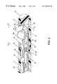
- FIG. 1is an overall view of a catheter system having a movable ball electrode at its distal tip section constructed in accordance with the principles of the present invention.
- FIG. 2is a close-up view of the distal section of the catheter system comprising a movable ball electrode inside an elongated pocket at the distal end having fluid infusion and irrigation capabilities.
- FIG. 3is a side cross-sectional view of the distal section comprising a movable ball electrode at one side of the tip section of section A—A of FIG. 2 .
- FIG. 4is a top cross-sectional view of the distal section comprising a movable ball electrode at one side of the tip section of section B—B of FIG. 2 .
- FIG. 1shows an overall view of the catheter system having a movable ball electrode and fluid infusion and irrigation means for cooling down the ablation electrodes.
- a catheter system constructed in accordance with the principles of the present inventioncomprises: a catheter shaft 1 having a distal tip section 2 , a distal end 7 , a proximal end 10 , and at least one lumen 29 extending between the distal end 7 and the proximal end 10 .
- the catheter systemcomprises a fluid infusion mechanism 11 close to the proximal end 10 of the catheter shaft 1 .
- a control valve 12is provided to the fluid infusion mechanism 11 which is externally connected to a fluid supply source having a fluid pump and means for controlling the flow rate of fluid through the lumen or fluid passageway to optimize the cooling of the ablation electrode of the catheter system.
- a handle 4is attached to the proximal end 10 of said catheter shaft 1 .
- the connector 3 secured at the proximal end of the catheter systemis part of the handle section 4 .
- the handlehas one steering mechanism 5 .
- the steering mechanism 5is to deflect the tip section 2 of the catheter shaft 1 for catheter maneuvering and positioning. In one embodiment, by pushing forward the front plunger 8 of the handle 4 , the tip section 2 of the catheter shaft 1 deflects to one direction. By pulling back the front plunger 8 , the tip section returns to its neutral position.
- the steering mechanism 5 at the handle 4comprises means for providing a plurality of deflectable curves on the distal tip section 2 of the catheter shaft.
- a catheter having multiple-curve deflection capabilitiesis disclosed in U.S. Pat. No. 5,782,828, and cited here as reference.
- FIG. 2shows a close-up view of the distal section of the catheter system comprising a movable ball electrode at the distal end having fluid infusion and irrigation capabilities.
- a fluid conveying lumen or passageway 13 and its outlet 27is associated with the elongate catheter shaft 1 , and is preferably disposed within the catheter shaft along the longitudinal axis thereof.
- the fluid conveying lumenis adapted to communicate with a fluid supply source to convey fluid from the source and through said lumen to be discharged out of the tip section 2 containing a ball electrode 14 and an opening 24 .
- the fluid flow rate from the fluid infusion mechanism 11may be between approximately 5 ml/min to 50 ml/min.
- the tip section 2 of the catheter shaft 1comprises a tip electrode 15 or a band electrode 16 .
- the electrodesare formed of conducting materials selected from the group of platinum, iridium, gold, silver, stainless steel, conductive elastomer, and Nitinol.
- the electrodeis encoded with at least one marker 17 that is visible to ultrasonic energy.
- marker 17is provided in the form of encapsulated air bubbles.
- At least one marker 17is placed in the proximity of the electrode 14 in a way so that the exact location of the tip section 2 is visible to an external ultrasonic energy.
- the bubble in a markercan be formed by introducing air by a syringe penetrating the wall of the catheter shaft of said catheter system and thereafter is sealed by epoxy.
- the catheter systemcomprises a flat wire means 18 that is disposed inside the lumen of the catheter shaft 1 .
- the proximal end of said flat wire meansis secured to a deployment means 6 on the handle 4 of said catheter system, and is further connected to a conducting wire which is soldered to a contact pin of the connector 3 .
- the at least one electrode 15 or 16has an insulated conducting wire 19 secured to the electrode, which passes through the lumen 29 of the catheter shaft 1 and is soldered to a contact pin of the connector 3 at the proximal end of the handle 4 .
- the conducting wire from the connector endis externally connected to an EKG for diagnosis or to a RF current generator during an electrophysiology ablation procedure. Therefrom, the RF current is transmitted through the conducting wire to the electrode and delivered the RF energy to the target tissue.
- a temperature sensor 20is constructed at the proximity of the electrode 14 , 15 , or 16 to measure the tissue contact temperature when RF energy is delivered.
- the temperature sensing wire 21 from the thermocouple or thermisteris connected to one of the contact pins of the connector 3 and externally connected to a transducer and to a temperature controller.
- the temperature readingis thereafter relayed to a closed-loop control mechanism to adjust the RF current output.
- the RF current deliveredis thus controlled by the temperature sensor reading or by a pre-programmed control algorithm.
- the ball 14is free to float, roll, rotate, and move within the elongated hollow pocket 23 .
- the flat wire means 18 with guiding guards 28 and 38 at its distal portionis to control the ball movement forwardly and backwardly within the hollow pocket 23 so that a long linear lesion may be created without moving the catheter shaft.
- FIG. 3shows a side cross-sectional view of the distal section comprising a movable ball electrode 14 at one side of the tip section 2 of section A—A of FIG. 2 .
- the distal guiding guard 28 and the proximal guiding guard 38define the position of the ball 14 within the flat wire means 18 .
- FIG. 4shows a top cross-sectional view of the distal section comprising a movable ball electrode 14 at one side of the tip section 2 of section B—B of FIG. 2 .
- the movable ball electrode 14can move from position 14 A to another position 14 B, 14 C or 14 D within the elongated pocket 23 by the control of the flat wire means 18 from the control mechanism 6 on the handle 4 .
- the opening 24is defined by a distal line 31 , a proximal line 32 , and two sidelines 33 and 34 of the catheter shaft 1 .
- the catheter system of this inventionis also to provide fluid communication and commensurate flow of fluid originating inside the tip section of the catheter shaft to the electrode exterior surface, which directs the fluid flow from inside the catheter shaft over the exterior surface of the electrode to provide a fluid protective layer surrounding the ball electrode to minimize temperature elevation of the electrode with biological tissues.
- This fluid protective layer surrounding the movable ball electrodeis better maintained when the ball 14 of the ball electrode is freely rotatable and movable within the elongated pocket 23 .
- a silicone type check valve 22is installed at certain opening of the lumen 29 .
Landscapes
- Health & Medical Sciences (AREA)
- Engineering & Computer Science (AREA)
- Life Sciences & Earth Sciences (AREA)
- Veterinary Medicine (AREA)
- Biomedical Technology (AREA)
- Nuclear Medicine, Radiotherapy & Molecular Imaging (AREA)
- Animal Behavior & Ethology (AREA)
- General Health & Medical Sciences (AREA)
- Public Health (AREA)
- Radiology & Medical Imaging (AREA)
- Surgery (AREA)
- Cardiology (AREA)
- Physics & Mathematics (AREA)
- Plasma & Fusion (AREA)
- Otolaryngology (AREA)
- Heart & Thoracic Surgery (AREA)
- Medical Informatics (AREA)
- Molecular Biology (AREA)
- Surgical Instruments (AREA)
Abstract
Description
Claims (20)
Priority Applications (1)
| Application Number | Priority Date | Filing Date | Title |
|---|---|---|---|
| US09/200,907US6226554B1 (en) | 1997-06-02 | 1998-11-27 | Catheter system having a ball electrode and methods thereof |
Applications Claiming Priority (2)
| Application Number | Priority Date | Filing Date | Title |
|---|---|---|---|
| US08/867,469US5843152A (en) | 1997-06-02 | 1997-06-02 | Catheter system having a ball electrode |
| US09/200,907US6226554B1 (en) | 1997-06-02 | 1998-11-27 | Catheter system having a ball electrode and methods thereof |
Related Parent Applications (1)
| Application Number | Title | Priority Date | Filing Date |
|---|---|---|---|
| US08/867,469Continuation-In-PartUS5843152A (en) | 1997-05-19 | 1997-06-02 | Catheter system having a ball electrode |
Publications (1)
| Publication Number | Publication Date |
|---|---|
| US6226554B1true US6226554B1 (en) | 2001-05-01 |
Family
ID=46256194
Family Applications (1)
| Application Number | Title | Priority Date | Filing Date |
|---|---|---|---|
| US09/200,907Expired - LifetimeUS6226554B1 (en) | 1997-06-02 | 1998-11-27 | Catheter system having a ball electrode and methods thereof |
Country Status (1)
| Country | Link |
|---|---|
| US (1) | US6226554B1 (en) |
Cited By (26)
| Publication number | Priority date | Publication date | Assignee | Title |
|---|---|---|---|---|
| US6595979B1 (en) | 2001-07-10 | 2003-07-22 | Myocardial Therapeutics, Inc. | Methods for sterile aspiration/reinjection of bodily fluid |
| US6702810B2 (en) | 2000-03-06 | 2004-03-09 | Tissuelink Medical Inc. | Fluid delivery system and controller for electrosurgical devices |
| US6733485B1 (en) | 2001-05-25 | 2004-05-11 | Advanced Bionics Corporation | Microstimulator-based electrochemotherapy methods and systems |
| US6740083B2 (en)* | 2001-07-09 | 2004-05-25 | Scimed Life Systems, Inc. | Distal catheter assembly with proximal mounting member |
| US6796957B2 (en) | 2001-07-10 | 2004-09-28 | Myocardial Therapeutics, Inc. | Sterile aspiration/reinjection systems |
| US6796963B2 (en) | 2001-07-10 | 2004-09-28 | Myocardial Therapeutics, Inc. | Flexible tissue injection catheters with controlled depth penetration |
| US6835193B2 (en) | 2001-07-10 | 2004-12-28 | Myocardial Therapeutics, Inc. | Methods for controlled depth injections into interior body cavities |
| US20050015085A1 (en)* | 2002-02-12 | 2005-01-20 | Tissuelink Medical, Inc. | Fluid-assisted medical devices, systems and methods |
| WO2005112814A3 (en)* | 2004-05-17 | 2006-04-06 | Bard Inc C R | Irrigated catheter |
| US20070156132A1 (en)* | 2005-12-30 | 2007-07-05 | Darrell Drysen | Injection molded irrigated tip electrode and catheter having the same |
| US20080039745A1 (en)* | 2006-08-08 | 2008-02-14 | Bacoustics Llc | Ablative ultrasonic-cryogenic apparatus |
| US20080082099A1 (en)* | 2006-09-29 | 2008-04-03 | Duane Dickens | Surgical probe and methods for targeted treatment of heart structures |
| US7537595B2 (en) | 2001-12-12 | 2009-05-26 | Tissuelink Medical, Inc. | Fluid-assisted medical devices, systems and methods |
| US20090221955A1 (en)* | 2006-08-08 | 2009-09-03 | Bacoustics, Llc | Ablative ultrasonic-cryogenic methods |
| US7604635B2 (en) | 2000-03-06 | 2009-10-20 | Salient Surgical Technologies, Inc. | Fluid-assisted medical devices, systems and methods |
| US7645277B2 (en) | 2000-09-22 | 2010-01-12 | Salient Surgical Technologies, Inc. | Fluid-assisted medical device |
| US20100049183A1 (en)* | 2007-02-19 | 2010-02-25 | The Graduate School For The Creation Of New Photonics Industries | Skull cutting device |
| US7727232B1 (en) | 2004-02-04 | 2010-06-01 | Salient Surgical Technologies, Inc. | Fluid-assisted medical devices and methods |
| US7811282B2 (en) | 2000-03-06 | 2010-10-12 | Salient Surgical Technologies, Inc. | Fluid-assisted electrosurgical devices, electrosurgical unit with pump and methods of use thereof |
| US7951148B2 (en) | 2001-03-08 | 2011-05-31 | Salient Surgical Technologies, Inc. | Electrosurgical device having a tissue reduction sensor |
| US8328798B2 (en) | 1999-10-02 | 2012-12-11 | Quantumcor, Inc | Method for treating and repairing mitral valve annulus |
| US8475455B2 (en) | 2002-10-29 | 2013-07-02 | Medtronic Advanced Energy Llc | Fluid-assisted electrosurgical scissors and methods |
| US8968299B2 (en) | 2006-10-10 | 2015-03-03 | St. Jude Medical, Atrial Fibrillation Division, Inc. | Circuit for a catheter or sheath and method of forming same |
| US20150250982A1 (en)* | 2014-03-05 | 2015-09-10 | Oscor Inc. | Intravascular sheath with mapping capabilities to deliver therapeutic devices to a targeted location within a blood vessel |
| US9204921B2 (en) | 2012-12-13 | 2015-12-08 | Cook Medical Technologies Llc | RF energy controller and method for electrosurgical medical devices |
| US9364277B2 (en) | 2012-12-13 | 2016-06-14 | Cook Medical Technologies Llc | RF energy controller and method for electrosurgical medical devices |
Citations (1)
| Publication number | Priority date | Publication date | Assignee | Title |
|---|---|---|---|---|
| US5916214A (en)* | 1995-05-01 | 1999-06-29 | Medtronic Cardiorhythm | Dual curve ablation catheter |
- 1998
- 1998-11-27USUS09/200,907patent/US6226554B1/ennot_activeExpired - Lifetime
Patent Citations (1)
| Publication number | Priority date | Publication date | Assignee | Title |
|---|---|---|---|---|
| US5916214A (en)* | 1995-05-01 | 1999-06-29 | Medtronic Cardiorhythm | Dual curve ablation catheter |
Cited By (46)
| Publication number | Priority date | Publication date | Assignee | Title |
|---|---|---|---|---|
| US8328798B2 (en) | 1999-10-02 | 2012-12-11 | Quantumcor, Inc | Method for treating and repairing mitral valve annulus |
| US8361068B2 (en) | 2000-03-06 | 2013-01-29 | Medtronic Advanced Energy Llc | Fluid-assisted electrosurgical devices, electrosurgical unit with pump and methods of use thereof |
| US7815634B2 (en) | 2000-03-06 | 2010-10-19 | Salient Surgical Technologies, Inc. | Fluid delivery system and controller for electrosurgical devices |
| US7811282B2 (en) | 2000-03-06 | 2010-10-12 | Salient Surgical Technologies, Inc. | Fluid-assisted electrosurgical devices, electrosurgical unit with pump and methods of use thereof |
| US7604635B2 (en) | 2000-03-06 | 2009-10-20 | Salient Surgical Technologies, Inc. | Fluid-assisted medical devices, systems and methods |
| US8038670B2 (en) | 2000-03-06 | 2011-10-18 | Salient Surgical Technologies, Inc. | Fluid-assisted medical devices, systems and methods |
| US8048070B2 (en) | 2000-03-06 | 2011-11-01 | Salient Surgical Technologies, Inc. | Fluid-assisted medical devices, systems and methods |
| US7115139B2 (en) | 2000-03-06 | 2006-10-03 | Tissuelink Medical Inc. | Fluid-assisted medical devices, fluid delivery systems and controllers for such devices, and methods |
| US6702810B2 (en) | 2000-03-06 | 2004-03-09 | Tissuelink Medical Inc. | Fluid delivery system and controller for electrosurgical devices |
| US7651494B2 (en) | 2000-09-22 | 2010-01-26 | Salient Surgical Technologies, Inc. | Fluid-assisted medical device |
| US7645277B2 (en) | 2000-09-22 | 2010-01-12 | Salient Surgical Technologies, Inc. | Fluid-assisted medical device |
| US7951148B2 (en) | 2001-03-08 | 2011-05-31 | Salient Surgical Technologies, Inc. | Electrosurgical device having a tissue reduction sensor |
| US6733485B1 (en) | 2001-05-25 | 2004-05-11 | Advanced Bionics Corporation | Microstimulator-based electrochemotherapy methods and systems |
| US6740083B2 (en)* | 2001-07-09 | 2004-05-25 | Scimed Life Systems, Inc. | Distal catheter assembly with proximal mounting member |
| US6595979B1 (en) | 2001-07-10 | 2003-07-22 | Myocardial Therapeutics, Inc. | Methods for sterile aspiration/reinjection of bodily fluid |
| US6835193B2 (en) | 2001-07-10 | 2004-12-28 | Myocardial Therapeutics, Inc. | Methods for controlled depth injections into interior body cavities |
| US6796963B2 (en) | 2001-07-10 | 2004-09-28 | Myocardial Therapeutics, Inc. | Flexible tissue injection catheters with controlled depth penetration |
| US6796957B2 (en) | 2001-07-10 | 2004-09-28 | Myocardial Therapeutics, Inc. | Sterile aspiration/reinjection systems |
| US7537595B2 (en) | 2001-12-12 | 2009-05-26 | Tissuelink Medical, Inc. | Fluid-assisted medical devices, systems and methods |
| US20050015085A1 (en)* | 2002-02-12 | 2005-01-20 | Tissuelink Medical, Inc. | Fluid-assisted medical devices, systems and methods |
| US7998140B2 (en) | 2002-02-12 | 2011-08-16 | Salient Surgical Technologies, Inc. | Fluid-assisted medical devices, systems and methods |
| US8475455B2 (en) | 2002-10-29 | 2013-07-02 | Medtronic Advanced Energy Llc | Fluid-assisted electrosurgical scissors and methods |
| US7727232B1 (en) | 2004-02-04 | 2010-06-01 | Salient Surgical Technologies, Inc. | Fluid-assisted medical devices and methods |
| US8075557B2 (en) | 2004-02-04 | 2011-12-13 | Salient Surgical Technologies, Inc. | Fluid-assisted medical devices and methods |
| WO2005112814A3 (en)* | 2004-05-17 | 2006-04-06 | Bard Inc C R | Irrigated catheter |
| US8894642B2 (en) | 2004-05-17 | 2014-11-25 | Boston Scientific Scimed, Inc. | Irrigated catheter |
| EP2368512A1 (en)* | 2004-05-17 | 2011-09-28 | C.R. Bard, Inc. | Irrigated catheter |
| US20070156132A1 (en)* | 2005-12-30 | 2007-07-05 | Darrell Drysen | Injection molded irrigated tip electrode and catheter having the same |
| US7857809B2 (en)* | 2005-12-30 | 2010-12-28 | Biosense Webster, Inc. | Injection molded irrigated tip electrode and catheter having the same |
| US20080039745A1 (en)* | 2006-08-08 | 2008-02-14 | Bacoustics Llc | Ablative ultrasonic-cryogenic apparatus |
| US8062289B2 (en) | 2006-08-08 | 2011-11-22 | Bacoustics, Llc | Ablative ultrasonic-cryogenic apparatus |
| US7540870B2 (en) | 2006-08-08 | 2009-06-02 | Bacoustics, Llc | Ablative ultrasonic-cryogenic apparatus |
| US20090221955A1 (en)* | 2006-08-08 | 2009-09-03 | Bacoustics, Llc | Ablative ultrasonic-cryogenic methods |
| US8187266B2 (en) | 2006-09-29 | 2012-05-29 | Quantumcor, Inc. | Surgical probe and methods for targeted treatment of heart structures |
| US20080082099A1 (en)* | 2006-09-29 | 2008-04-03 | Duane Dickens | Surgical probe and methods for targeted treatment of heart structures |
| US8968299B2 (en) | 2006-10-10 | 2015-03-03 | St. Jude Medical, Atrial Fibrillation Division, Inc. | Circuit for a catheter or sheath and method of forming same |
| US9247990B2 (en) | 2006-10-10 | 2016-02-02 | St. Jude Medical, Atrial Fibrillation Division, Inc. | Steerable sheath access device |
| US9364282B2 (en) | 2006-10-10 | 2016-06-14 | St. Jude Medical, Atrial Fibrillation Division, Inc. | Ablation electrode and catheter assembly for epicardial mapping and ablation with directionally focused RF energy |
| US10285753B2 (en) | 2006-10-10 | 2019-05-14 | St. Jude Medical, Atrial Fibrillation Division, Inc. | Circuit for a catheter or sheath and method of forming same |
| US11419673B2 (en) | 2006-10-10 | 2022-08-23 | St. Jude Medical, Atrial Fibrillation Division, Inc. | Steerable sheath access device |
| US20100049183A1 (en)* | 2007-02-19 | 2010-02-25 | The Graduate School For The Creation Of New Photonics Industries | Skull cutting device |
| US8790333B2 (en)* | 2007-02-19 | 2014-07-29 | The Graduate for the Creation of New Photonics Industries | Skull cutting device |
| US9204921B2 (en) | 2012-12-13 | 2015-12-08 | Cook Medical Technologies Llc | RF energy controller and method for electrosurgical medical devices |
| US9364277B2 (en) | 2012-12-13 | 2016-06-14 | Cook Medical Technologies Llc | RF energy controller and method for electrosurgical medical devices |
| US20150250982A1 (en)* | 2014-03-05 | 2015-09-10 | Oscor Inc. | Intravascular sheath with mapping capabilities to deliver therapeutic devices to a targeted location within a blood vessel |
| US9844644B2 (en)* | 2014-03-05 | 2017-12-19 | Oscor Inc. | Intravascular sheath with mapping capabilities to deliver therapeutic devices to a targeted location within a blood vessel |
Similar Documents
| Publication | Publication Date | Title |
|---|---|---|
| US5843152A (en) | Catheter system having a ball electrode | |
| US6226554B1 (en) | Catheter system having a ball electrode and methods thereof | |
| US5876399A (en) | Catheter system and methods thereof | |
| US5893884A (en) | Catheter system having rollable electrode means | |
| US6033403A (en) | Long electrode catheter system and methods thereof | |
| US6217576B1 (en) | Catheter probe for treating focal atrial fibrillation in pulmonary veins | |
| US6238390B1 (en) | Ablation catheter system having linear lesion capabilities | |
| US5938659A (en) | Catheter system having cooled multiple-needle electrode and methods thereof | |
| US5913856A (en) | Catheter system having a porous shaft and fluid irrigation capabilities | |
| US5891137A (en) | Catheter system having a tip with fixation means | |
| US5971968A (en) | Catheter probe having contrast media delivery means | |
| US6241726B1 (en) | Catheter system having a tip section with fixation means | |
| US6063080A (en) | Linear catheter ablation system | |
| US10945780B2 (en) | Cryogenic balloon device with electroporation treatment region | |
| US6029091A (en) | Catheter system having lattice electrodes | |
| US20050177151A1 (en) | Irrigation sheath | |
| US6290697B1 (en) | Self-guiding catheter system for tissue ablation | |
| US5782900A (en) | Catheter system having safety means | |
| US5876398A (en) | Method and apparatus for R-F ablation | |
| US6156033A (en) | Ablation catheter having electrode means and methods thereof | |
| US5921982A (en) | Systems and methods for ablating body tissue | |
| US6178354B1 (en) | Internal mechanism for displacing a slidable electrode | |
| US5500012A (en) | Ablation catheter system | |
| US7147633B2 (en) | Method and apparatus for treatment of atrial fibrillation | |
| US7371235B2 (en) | Ablation systems including insulated energy transmitting elements |
Legal Events
| Date | Code | Title | Description |
|---|---|---|---|
| STCF | Information on status: patent grant | Free format text:PATENTED CASE | |
| AS | Assignment | Owner name:SILICON VALLEY BANK, CALIFORNIA Free format text:SECURITY INTEREST;ASSIGNOR:IRVINE BIOMEDICAL, INC.;REEL/FRAME:013625/0352 Effective date:20021112 | |
| FPAY | Fee payment | Year of fee payment:4 | |
| AS | Assignment | Owner name:IRVINE BIOMEDICAL, INC., CALIFORNIA Free format text:ASSIGNMENT OF ASSIGNORS INTEREST;ASSIGNORS:TU, HOSHENG (AKA ROGER TU);TU, LILY CHEN;TU, STEVE CHUN-GUANG;REEL/FRAME:015676/0259 Effective date:20040731 | |
| AS | Assignment | Owner name:IRVINE BIOMEDICAL, INC., CALIFORNIA Free format text:RELEASE BY SECURED PARTY;ASSIGNOR:SILICON VALLEY BANK;REEL/FRAME:015886/0107 Effective date:20041007 | |
| FEPP | Fee payment procedure | Free format text:PAT HOLDER NO LONGER CLAIMS SMALL ENTITY STATUS, ENTITY STATUS SET TO UNDISCOUNTED (ORIGINAL EVENT CODE: STOL); ENTITY STATUS OF PATENT OWNER: LARGE ENTITY | |
| FEPP | Fee payment procedure | Free format text:PAT HOLDER NO LONGER CLAIMS SMALL ENTITY STATUS, ENTITY STATUS SET TO UNDISCOUNTED (ORIGINAL EVENT CODE: STOL); ENTITY STATUS OF PATENT OWNER: LARGE ENTITY Free format text:PAT HOLDER CLAIMS SMALL ENTITY STATUS, ENTITY STATUS SET TO SMALL (ORIGINAL EVENT CODE: LTOS); ENTITY STATUS OF PATENT OWNER: LARGE ENTITY | |
| REFU | Refund | Free format text:REFUND - PAYMENT OF MAINTENANCE FEE, 8TH YR, SMALL ENTITY (ORIGINAL EVENT CODE: R2552); ENTITY STATUS OF PATENT OWNER: LARGE ENTITY | |
| FPAY | Fee payment | Year of fee payment:8 | |
| FPAY | Fee payment | Year of fee payment:12 |