US6226338B1 - Multiple channel data communication buffer with single transmit and receive memories - Google Patents
Multiple channel data communication buffer with single transmit and receive memoriesDownload PDFInfo
- Publication number
- US6226338B1 US6226338B1US09/099,563US9956398AUS6226338B1US 6226338 B1US6226338 B1US 6226338B1US 9956398 AUS9956398 AUS 9956398AUS 6226338 B1US6226338 B1US 6226338B1
- Authority
- US
- United States
- Prior art keywords
- write
- input
- read
- transmit
- data
- Prior art date
- Legal status (The legal status is an assumption and is not a legal conclusion. Google has not performed a legal analysis and makes no representation as to the accuracy of the status listed.)
- Expired - Lifetime
Links
Images


Classifications
- G—PHYSICS
- G06—COMPUTING OR CALCULATING; COUNTING
- G06F—ELECTRIC DIGITAL DATA PROCESSING
- G06F5/00—Methods or arrangements for data conversion without changing the order or content of the data handled
- G06F5/06—Methods or arrangements for data conversion without changing the order or content of the data handled for changing the speed of data flow, i.e. speed regularising or timing, e.g. delay lines, FIFO buffers; over- or underrun control therefor
- G06F5/065—Partitioned buffers, e.g. allowing multiple independent queues, bidirectional FIFO's
- H—ELECTRICITY
- H04—ELECTRIC COMMUNICATION TECHNIQUE
- H04J—MULTIPLEX COMMUNICATION
- H04J3/00—Time-division multiplex systems
- H04J3/02—Details
- H04J3/06—Synchronising arrangements
- H04J3/062—Synchronisation of signals having the same nominal but fluctuating bit rates, e.g. using buffers
- H—ELECTRICITY
- H04—ELECTRIC COMMUNICATION TECHNIQUE
- H04L—TRANSMISSION OF DIGITAL INFORMATION, e.g. TELEGRAPHIC COMMUNICATION
- H04L25/00—Baseband systems
- H04L25/02—Details ; arrangements for supplying electrical power along data transmission lines
- H04L25/05—Electric or magnetic storage of signals before transmitting or retransmitting for changing the transmission rate
Definitions
- the present inventionrelates to integrated circuits for data communication systems such as network devices and telecommunications circuits. More particularly, the present invention relates to a multiple channel data buffer for use in an integrated circuit.
- Data communication circuitssuch as network devices and telecommunication circuits typically have several communication channels for connecting to multiple devices such as workstations, telephone and television systems, video teleconferencing systems and other facilities over common data links or carriers.
- a channelis a logical path from one source to one destination and can be unidirectional or bidirectional.
- a data routing circuitsuch as a direct memory access (DMA) controller, routes data to and from each channel.
- Each channelincludes a data interface controller, such as a serial wide area network (SWAN) controller or a local area network (LAN) controller.
- SWANserial wide area network
- LANlocal area network
- Each data interface controlleris coupled to the data routing circuit for controlling transmission of its respective data over the data link or carrier.
- Data interface controllersare often configured to transmit packets of data having an arbitrary length at a fixed speed.
- a WAN controllermay transmit an Internet Protocol (IP) packet over a fixed speed Interactive Services Digital Network (ISDN) Basic Rate Interface (BRI) using high level data link control (HDLC) framing.
- IPInternet Protocol
- ISDNInteractive Services Digital Network
- BTIBasic Rate Interface
- HDLChigh level data link control
- a LAN controllersuch as an Ethernet controller may transmit an IP packet over a fixed speed 10 or 100 Mbps LAN.
- a first-in-first-out (FIFO) memoryfor buffering transmit and receive data between the DMA controller and each data interface controller.
- Each communication channelhas its own transmit FIFO and its own receive FIFO.
- Each FIFOuses a dual port random access memory (RAM) for storing the data.
- One portis used by the data interface controller and the other port is used by the data routing circuit.
- the DMA controllerwrites the data packets to one end of the FIFO at a DMA transmission rate
- the data interface controllerreads the packets at the other end of the FIFO at the rate of the fixed speed data interface.
- the FIFOis needed because the DMA transmission rate is generally substantially higher on average than the rate of the fixed speed data interface. Also, the DMA controller is subject to “gaps” in its ability to feed the FIFO because of memory access latencies, contention with other master devices that are coupled to the memory bus and control logic overhead.
- each FIFOmust have its own address decode logic for writing into the FIFO and reading out of the FIFO.
- the requirement for multiple address decode logic circuitsadds to the number of semiconductor devices or “gates” on the integrated circuit and requires more interconnections to be routed between the gates on the integrated circuit.
- Each FIFOmust also have its own logic for maintaining status flags related to the number of data entries stored in the FIFO, such as an “almost empty” flag and an “almost full” flag. This also adds to the number of gates and interconnections on the integrated circuit.
- each FIFOis a separate module on the integrated circuit, there are more interconnections that must be routed between each FIFO and its source and destination. Improved data communication buffer circuits are desired.
- the multiple-channel data communication buffer of the present inventionincludes a transmit first-in-first-out (“FIFO”) circuit and a receive FIFO circuit.
- the transmit and receive FIFO circuitseach include a write pointer array, a read pointer array and a single memory device having a data input, a data output, a write address input, a read address input and a plurality of logical channels from the data input to the data output.
- the write pointer arrayhas a write pointer for each of the logical channels and applies a selected one of the write pointers to the write address input based on a write channel number input.
- the read pointer arrayhas a read pointer for each of the logical channels and applies a selected one of the read pointers to the read address input based on a read channel number input.
- FIG. 1is a block diagram of a data communication circuit according to one embodiment of the present invention.
- FIG. 2is a block diagram of a data communication circuit according to another embodiment of the present invention.
- FIG. 3is a block diagram of a transmit FIFO within the data communication circuits shown in FIGS. 1 and 2.
- FIG. 4is a diagram illustrating an example of the function of an address multiplexer within the transmit FIFO shown in FIG. 3 .
- FIG. 5is a diagram illustrating another example of the function of the address multiplexer within the transmit FIFO shown in FIG. 3 .
- FIG. 6is a waveform diagram illustrating various waveforms in the transmit FIFO shown in FIG. 3 over time.
- FIG. 7is a block diagram of a receive FIFO within the data communication circuits shown in FIGS. 1 and 2 .
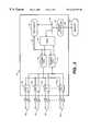
- FIG. 1is a block diagram of a data communication circuit according to one embodiment of the present invention.
- Data communication circuit 10includes physical channel 12 , multiple channel physical layer core 14 , transmit first-in-first-out (FIFO) buffer 16 , receive FIFO buffer 18 , direct memory access (DMA) controller 20 , processor 22 , system bus 24 , memory controller 26 and memory 30 .
- FIFOfirst-in-first-out
- DMAdirect memory access
- processor 22processor 22
- system bus 24system bus 24
- memory controller 26memory controller 26 and memory 30 .
- multiple channel physical layer core 14 , transmit and receive FIFOs 16 and 18 , DMA controller 20 , processor 22 , system bus 24 and memory controller 26are all fabricated on a single semiconductor integrated circuit 32 , such as an application specific integrated circuit (ASIC).
- ASICapplication specific integrated circuit
- Physical channel 12includes a transmit data link or carrier 40 and a receive data link or carrier 42 which are coupled to Physical Layer (PHY) devices 44 and 46 , respectively, for interfacing with transmit and receive data links 40 and 42 .
- PHYPhysical Layer
- physical channel 12includes an ISDN line or frame relay (T1/E1 or fractional T1/E1) line, for example.
- Core 14includes a data interface controller for controlling data communication from DMA controller 20 to physical channel 12 along multiple logical channels.
- the data interface controllerincludes a time division multiplexer (TDM) which multiplexes the data transfers within each logical channel with the data transfers within the other logical channels over physical channel 12 .
- TDMtime division multiplexer
- core 14supports up to 32 time division multiplexed channels.
- Core 14is coupled to DMA controller 20 through transmit FIFO 16 and receive FIFO 18 .
- Transmit FIFO 16 and receive FIFO 18each include a single random access memory (RAM) device for buffering data between core 14 and DMA controller 20 .
- RAMrandom access memory
- the memory locations within each RAM deviceare divided into blocks, or “queues”, with one queue being associated with a corresponding one of the logical channels.
- Transmit FIFO 16 and receive FIFO 18further include queue parameter inputs 34 and 36 , respectively, for receiving programmable queue parameters from processor 22 .
- the programmable queue parametersallow processor 22 to configure transmit FIFO 16 and receive FIFO 18 to have selected number of logical channels and a selected number of memory locations in each channel.
- Processor 22can change the queue parameters and thus the number of channels supported by FIFOs 16 and 18 to suit a particular application.
- FIFOs 16 and 18can be programmed to include 32, 16, 8 or 4 logical channels, with each channel having 64, 128, 256 or 512 memory locations, respectively.
- DMA controller 20is coupled to processor 22 and memory controller 26 over system bus 24 .
- DMA controller 20arbitrates for access to system bus 24 with processor 22 .
- Memory controller 26is coupled between system bus 24 and external memory 30 for controlling data transfers to and from memory 30 by DMA controller 20 and processor 22 .
- Memory controller 26can be located on integrated circuit 32 or can be a separate module from integrated circuit 32 .
- DMA controller 20operates as a data routing circuit, under the control of processor 22 , which routes transmit data in multiple-bit data frames or packets from external memory 30 to one of the logical channels in transmit FIFO 16 .
- DMA controller 20also routes receive data from one of the logical channels in receive FIFO 18 to external memory 30 , to another device coupled to system bus 24 , or to one of the logical channels within transmit FIFO 18 .
- DMA controller 20transfers each data frame a byte or word at a time until the entire data frame has been transferred.
- DMA controller 20notifies processor 22 only when the data transfer of the entire data frame is complete.
- Data routing circuits other than a DMA controller, such as a processorcan also be used in alternative embodiments of the present invention.
- processor 22notifies DMA controller 20 that there is a data frame in memory 30 to be transferred through a selected logical channel.
- DMA controller 20passes successive words or bytes of the data frame from memory 30 , through memory controller 26 to successive entries within the queue that corresponds to the selected logical channel within transmit FIFO 16 .
- DMA controller 20continues to pass each successive word or byte of the data frame until the entire data frame has been transmitted, the queue in transmit FIFO 16 is full or another logical channel in transmit FIFO 16 having a higher priority requests service by DMA controller 20 .
- the data interface controller in core 14begins retrieving the stored words or bytes at a constant rate, beginning with the first word or byte that was passed by DMA controller 20 until the entire data frame has been extracted from transmit FIFO 16 .
- the data interface controller within core 14adds any necessary header information such as address and control information to the data, frames the header and data according to the selected protocol and then transmits the framed header and data through physical channel 12 .
- Transmit FIFO 16is needed because the rate that DMA controller 20 feeds each logical channel in transmit FIFO 16 is different on average then the fixed rate at which the data interface controller within core 14 retrieves data from each logical channel in transmit FIFO 16 . Also, DMA controller 20 is subject to “gaps” in its ability to feed individual logical channels in transmit FIFO 16 because of access latencies of memory 30 , contention on system bus 24 with other bus masters such as processor 22 , service of other logical channels in transmit FIFO 16 and control logic overhead.
- a multiple-bit data frameis received by core 14 within a selected logical channel over physical channel 12 .
- the data interface controller within core 14receives the data frame and passes successive words or bytes of the data frame to successive entries in the queue that corresponds to the selected logical channel within receive FIFO 18 until the entire data frame has been stored.
- DMA controller 20begins retrieving the words or bytes from receive FIFO 18 and stores the words or bytes in memory 30 until the entire data frame has been extracted from receive FIFO 18 .
- DMA controller 20then notifies processor 22 that the data transfer is complete.
- DMA controller 20may route the received data frame to another device coupled to system bus 24 or to one of the logical channels in transmit FIFO 16 .
- Processor 22can include an on-chip Reduced Instruction Set (RISCTM) processor, such a MIPS CW 4011 MiniRISCTM Superscalar Processor Core available from LSI Logic Corporation.
- processor 22can also include an off-chip processor, such as an i486 or i960 microprocessor manufactured by Intel Corporation.
- Memory 30can include a variety of memory types, such as a dynamic random access memory (DRAM), a static RAM or a flash memory, for example.
- DRAMdynamic random access memory
- static RAMstatic RAM
- flash memoryfor example.
- the data communication circuit shown in FIG. 1uses a single memory device for all logical channels in transmit FIFO 16 and a single memory device for all logical channels in receive FIFO 18 . This minimizes the area required for implementing the data buffer function on integrated circuit 32 . Additionally, by implementing queue parameter inputs 34 and 26 , the user of integrated circuit 32 can partition transmit FIFO 16 and receive FIFO 18 differently when applications require a different number of logical channels. For example, one application may require a large number of channels that transfer data at a slow rate. In this application, each logical channel would require only a small number of locations to store the data. Another application may require a small number of logical channels that transfer data at a much faster rate. In this application, each logical channel would require a much larger number of locations to store the data in order to maintain the faster data rate.
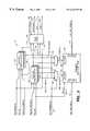
- FIG. 2is a block diagram of a data communication circuit 70 according to an alternative embodiment of the present invention.
- Data communication interface circuit 70is configured to coupled to a plurality of physical channels, labeled 12 0 - 12 N ⁇ 1 , where N is an integer greater than one.
- Data communication interface circuit 70includes a plurality physical of data interface controllers 72 0 - 72 N ⁇ 1 which are coupled between physical channels 12 0 - 12 N ⁇ 1 , respectively, and FIFOs 16 and 18 .
- Each data interface controller 72 0 - 72 N ⁇ 1reads data from a selected one of the logical channels within transmit FIFO 16 and writes data to the selected logical channel within receive FIFO 18 .
- several logical channelscan be time division multiplexed through one or more of data interface 72 N - 72 N ⁇ 1 controllers.
- Data interface controllers 72 0 - 72 N ⁇ 1are labeled “PHY 0”-“PHY N ⁇ 1” and can each include a Physical Layer device, for example, which interfaces with its respective physical channel 12 0 - 12 N ⁇ 1 .
- data interface controllers 72 0 - 72 N ⁇ 1can include serial wide area network (SWAN) controllers or local area network (LAN) controllers. These controllers can be configured to implement a desired protocol such as Ethernet, Frame Relay (T1/E1 or fractional T1/E1), ISDN basic rate interface (BRI), asynchronous transfer mode (ATM), ADSL and high level data link control (HDLC). Other types of data interface controllers or circuits can also be used.
- SWANserial wide area network
- LANlocal area network
- T1/E1 or fractional T1/E1ISDN basic rate interface
- ATMasynchronous transfer mode
- ADSLhigh level data link control
- Other types of data interface controllers or circuitscan also be used.
- FIG. 3is a block diagram showing transmit FIFO 16 in greater detail.
- Transmit FIFO 16includes transmit RAM 100 , write pointer array 102 , read pointer array 104 , flag logic 106 and address multiplexers 108 and 110 .
- RAM 100includes a single synchronous 9-bit by 2048 entry dual port RAM having a write data input 112 , a write address input 114 , a write enable input 116 , a read data output 118 and a read address input 120 .
- RAM 100is capable of simultaneous read and write operations. However, the same entry cannot be written to and read from at the same time.
- Data input 112is coupled to transmit data input TxQ_DATA_IN[ 8 : 0 ] for receiving successive 8-bit data words and a one-bit end of frame (EOF) flag from DMA controller 20 (shown in FIG. 1 ).
- TxQindicates the signal is a transmit queue signal.
- Bit 7is the most significant bit of the data word, and bit 0 is the least significant bit of the data word.
- Bit 8is the EOF flag.
- DMA controller 20asserts bit 8 to a logic high level when the data on bits 7 - 0 contain the last byte of a transmit data frame. In some applications of the present invention, the EOF bit is not required.
- Write enable input 116is coupled to transmit queue write enable input TxQ_WR which is also provided by DMA controller 20 .
- DMA controller 20asserts this input to a logic high level when the DMA controller writes a data word to RAM 100 .
- DMA controller 20deasserts this input to a logic low level when the DMA controller is not writing.
- An absolute write addressis applied to write address input 114 by multiplexer 108 .
- RAM 100captures the data provided on TxQ_DATA_IN[ 8 : 0 ] and stores the data in the address location identified by the absolute write address applied to write address input 114 .
- Read data output 118is coupled to TxQ_DATA_OUT[ 8 : 0 ] for providing successive 8-bit data words and the corresponding EOF flag to multiple channel physical layer core 14 shown in FIG. 1 (or one of the data interface controllers shown in FIG. 2) for transmission within the selected logical channel.
- Bit 7is the most significant bit of the data word
- bit 0is the least significant bit of the data word.
- Bit 8is the EOF flag.
- RAM 100asserts bit 8 to a logic high level when the data on bits 7 - 0 contain the last byte of a transmit data frame.
- An absolute read addressis applied to read address input 120 by multiplexer 110 .
- RAM 100applies the data stored in the address location identified by the absolute read address to read data output 118 .
- Write pointer array 102 , read pointer array 104 and multiplexers 108 and 110generate the write and read addresses for RAM 100 based on signals received from DMA controller 20 and from core 14 shown in FIG. 1 (or the data interface controllers shown in FIG. 2 ).
- Write pointer array 102maintains a write address pointer for each logical channel within RAM 100 . These write pointers can be referred to as WR_PNTR_ 0 [ 8 : 0 ] for channel 0 , WR_PNTR_ 1 [ 8 : 0 ] for channel 1 , and so on.
- read pointer array 104maintains a read pointer for each logical channel in RAM 100 . These read pointers can be referred to as RD_PNTR_ 0 [ 8 : 0 ] for channel 0 , RD_PNTR_ 1 [ 8 : 0 ] for channel 1 , and so on.
- Transmit queue write pointer array 102is coupled to reset input TxQ_RST[ 31 : 0 ], transmit queue write channel input TXQ_WR_CHAN[ 4 : 0 ] and transmit queue write enable input TxQ_WR.
- Each write pointer maintained by write pointer array 102points to the address of the next entry to be written into the respective queue within RAM 100 for that logical channel.
- Write pointer array 102has a write pointer output 130 which is coupled to address multiplexer 108 and to flag logic 106 . In one embodiment, each write pointer has nine bits.
- DMA controller 20To write an entry into RAM 100 , DMA controller 20 provides a channel number on transmit queue write channel input TxQ_WR_CHAN[ 4 : 0 ] and provides a pulse on TXQ_WR.
- Write pointer array 102selects one of the write pointers based on the channel number received on TxQ_WR_CHAN[ 4 : 0 ] and applies that write pointer to write pointer output 130 as WR PNTR[ 8 : 0 ].
- Multiplexer 108combines selected bits of the write pointer applied to write pointer output 130 with selected bits of the channel number provided on TxQ_WR_CHAN[ 4 : 0 ] to form the absolute write address WR_ADDR[ 10 : 0 ] for RAM 100 .
- the absolute write addressis applied to write address input 114 .
- DMA controller 20activates TxQ_WR
- RAM 100captures the data provided on TxQ_DATA_IN[ 8 : 0 ] and stores the captured data in the address location identified by the absolute write address applied to write address input 114 .
- Write pointer array 102then increments the selected write pointer by one at the end of the write cycle as DMA controller 20 deactivates Tx_Q_WR.
- read pointer array 104maintains a read pointer for each logical channel. Each read pointer points to the address of the next entry to be read from the respective queue within RAM 100 for that logical channel.
- multiple channel physical layer core 14 shown in FIG. 1(or one of the data interface controllers shown in FIG. 2) provides the number of the logical channel to be read on transmit read channel input TxQ_RD_CHAN[ 4 : 0 ] and asserts TxQ_RD to a logic high state.
- Read pointer array 104selects one of the read pointers based on the channel number provided on TxQ_RD_CHAN[ 4 : 0 ] and applies that read pointer to read pointer output 132 as RD PNTR[ 8 : 0 ].
- Multiplexer 110combines selected bits of RD_PNTR[ 8 : 0 ] with selected bits of TXQ_RD_CHAN[ 4 : 0 ] to form the absolute read address RD_ADDR[ 10 : 0 ] for RAM 100 .
- the absolute read addressis applied to read address input 120 .
- RAM 100applies the data stored in the address location identified by RD_ADDR[ 10 : 0 ] to read data output 118 .
- TxQ_RDis deactivated.
- Read pointer array 104increments the selected read pointer at the end of the read cycle.
- Transmit queue parameter input TxQ_PARMS[ 1 : 0 ]is coupled to processor 22 as shown in FIGS. 1 and 2.
- Processor 22can vary the number and size of the logical channels within RAM 100 and addressed by pointer arrays 102 and 104 by varying the logical pattern formed by TxQ_PARMS[ 1 : 0 ].
- the following tableshows the number of channels and the number of entries per channel for each bit combination of TxQ_PARMS[ 1 : 0 ] according to one example of the present invention.
- RAM 100has a maximum of 32 logical channels with 64 bytes per channel and a minimum of four logical channels with 512 bytes per channel based on the binary combination formed by TxQ_PARMS[ 1 : 0 ].
- Write pointer array 102 and read pointer array 104use TxQ_PARMS[ 1 : 0 ] to select how many write and read pointers will be maintained and to select the number of address bits required to index through the selected number of bytes per channel. Each write and read pointer is incremented through these bits only. For example, with 32 channels and 64 bytes per channel, pointer arrays 102 and 104 maintain 32 write pointers and 32 read pointers, and each write and read pointer has six bits. With four channels and 512 bytes per channel, pointer arrays 102 and 104 maintain four write pointers and four read pointers, and each write and read pointer has nine bits.
- TxQ_PARMS[ 1 : 0 ]is also coupled to the select inputs of multiplexers 108 and 110 .
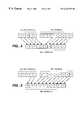
- FIG. 4is diagram illustrating the function performed by multiplexer 108 for an application in which there are 32 logical channels, with 64 bytes per channel. Since six pointer bits are required to address the 64 bytes per channel, multiplexer 108 selects the first six least significant bits WR_PNTR[ 5 : 0 ] of the write pointer as the first six least significant bits WR_ADDR[ 5 : 0 ] of the absolute write address WR_ADDR[ 10 : 0 ].
- multiplexer 108selects all five bits TxQ_WR_CHAN[ 4 : 0 ] of the write channel number as the five most significant bits WR_ADDR[ 10 : 6 ] of the absolute write address WR_ADDR[ 10 : 0 ].
- the five most significant bits of WR_ADDR[ 10 : 0 ]are used to select one of 32 different address blocks or “queues” within RAM 100 which corresponds to the 32 different logical channels.
- the six least significant bits of WR_ADDR[ 10 : 0 ]are used to index through the 64 entries within the address block that is selected by the channel number.
- FIG. 5is a diagram illustrating the function of multiplexer 108 when TxQ_PARMS[ 1 : 0 ] equals “ 00 ” such that there are four logical channels with 512 bytes per channel.
- Multiplexer 108selects all nine bits of WR_PNTR[ 8 : 0 ] to form the least significant nine bits WR_ADDR[ 8 : 0 ] of the absolute write address WR_ADDR[ 10 : 0 ].
- Multiplexer 108selects the two least significant bits TxQ_WR_CHAN[ 1 : 0 ] of the write channel number to form the two most significant bits WR_ADDR[ 10 : 9 ] of the absolute write address WR_ADDR[ 10 : 0 ].
- read address multiplexer 110operates substantially similar to write address multiplexer 108 .
- Multiplexers 108 and 110thus allow the number of channels and the number of storage locations per channel to be programmable through queue parameter input TxQ_PARMS[ 1 : 0 ].
- Flag logic 106is shared among all logical channels maintained by transmit FIFO 16 .
- Flag logic 106includes a write channel input 140 which is coupled to TxQ_WR_CHAN[ 4 : 0 ], a read channel input 141 which is coupled to TxQ_RD_CHAN[ 4 : 0 ], a parameter input 142 which is coupled to TxQ_PARMS[ 1 : 0 ], a write pointer input 143 which is coupled to write pointer array 102 and a read pointer input 144 which is coupled to read pointer array 104 .
- Flag logic 106generates a plurality of status flags on outputs 150 - 153 which are based on a comparison of the write and read pointers selected by the write and read channel numbers. Only one set of status flags are maintained by flag logic 106 . When the write or read channel numbers change, the appropriate status flags are changed accordingly to reflect the new pointer comparison. Hence, the status flags are valid only for the currently selected channel number.
- Flag logic 106generates an “ALMOST EMPTY” flag on output 150 which is provided to DMA controller 20 .
- Flag logic 106asserts the “ALMOST EMPTY” flag to a logic high level to inform DMA controller 20 that the queue in RAM 100 for the channel selected by TxQ_WR CHAN[ 4 : 0 ] is almost empty.
- flag logic 106deasserts the “ALMOST EMPTY” flag to a logic low level. This flag indicates to DMA controller 20 that the queue for the currently selected write channel is getting near empty so the DMA controller should increase the priority of getting data to this write channel so that the queue does not go completely empty.
- Flag logic 106generates a “BURST AVAIL” flag on output 151 .
- the “BURST AVAIL” flagis an indication that the transmit queue within RAM 100 for the currently selected channel has room to accommodate at least one data burst from DMA controller 20 . The size of each burst can be 16 or 32 bytes in length, for example.
- Flag logic 106generates a “START” flag on output 152 .
- This flagis provided to multiple channel physical layer core 14 which is shown in FIG. 1 (or to the corresponding data interface controller 72 which is shown in FIG. 2) to indicate that a sufficient amount of data is stored within the queue for the read channel identified by TxQ_RD_CHAN[ 4 : 0 ] for the device to begin extracting the data from the queue at a constant rate.
- flag logic 106asserts the START flag to a logic high level when the end of at least one data frame, as indicated by the EOF bit, is stored in the queue.
- the threshold at which flag logic 106 asserts the START flagis set to eight bytes (i.e.
- WR_PNTR_ 0 [ 8 : 0 ] ⁇ RD_PNTR_ 0 [ 8 : 0 ]>8 for read channel 0 ).
- the optimum threshold at which data is extracted from RAM 100depends on system design aspects such as memory bandwidth and latency.
- This flagis applied to multiple channel physical layer core 14 shown in FIG. 1 or to the corresponding data interface controller 72 shown in FIG. 2 .
- flag logic 106uses the write pointer and read pointer for the channel indicated by the write channel number when generating these flags. Since other queue status flags are used only by multiple channel physical layer core 14 (or the data interface controllers 72 ) during queue reads, flag logic 106 uses the write pointer and read pointer for the channel indicated by the read channel number when generating these flags.
- Transmit queue reset input TxQ_RST[ 31 : 0 ]is coupled to write pointer array 102 and read pointer array 104 .
- Bit 0corresponds to channel 0
- bit 1corresponds to channel 1
- DMA controller 20asserts each bit in TxQ_RST[ 31 : 0 ] to a logic high level for each logical channel that is enabled by processor 22 .
- DMA controller 20deasserts each bit in TxQ_RST[ 31 : 0 ] that corresponds to a logical channel that is disabled by processor 22 . If a particular bit is asserted, the corresponding write pointer and read pointer in arrays 102 and 104 are reset.
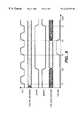
- FIG. 6is a waveform diagram illustrating various signals in transmit FIFO 16 over time.
- Clock signal CLKrepresents a system clock which is used by transmit FIFO 16 to synchronize the write and read operations.
- core logic 14or one of the data interface controllers 72 ) changes the read channel number TxQ_RD_CHAN[ 4 : 0 ].
- RAM 100applies to corresponding data byte to TxQ_DATA_OUT[ 8 : 0 ] and the transmit queue status flags (such as the START and EMPTY flags) become valid.
- core logic 14(or one of the data interface controllers 72 ) asserts TxQ_RD and captures the data on TxQ_DATA_OUT[ 8 : 0 ].
- core logic 14(or one of the data interface controllers 72 ) deasserts TxQ_RD, and the read pointer for the channel identified by TxQ_RD_CHAN[ 4 : 0 ] is incremented by one causing the data on TxQ_DATA_OUT[ 8 : 0 ] to change.
- the transmit queue status flags for the selected channelare updated to reflect the read pointer change.
- FIG. 7is a block diagram which illustrates receive FIFO 18 in greater detail.
- Receive FIFO 18is substantially similar to transmit FIFO 16 .
- Receive FIFO 18includes dual port RAM 200 , write pointer array 202 , read pointer array 204 , flag logic 206 and address multiplexers 208 and 210 .
- RAM 200includes a write data input 212 , a write address input 214 , a write enable input 216 , a read data output 218 and a read address input 220 .
- Data input 212is coupled to receive data input RxQ_DATA_IN[ 8 : 0 ] for receiving successive 8-bit data words and a one-bit end of frame (EOF) flag from the receiving device, such as core logic 14 shown in FIG.
- EEFend of frame
- RxQindicates the signal is a receive queue signal.
- Bit 8is the EOF flag. The receiving device asserts bit 8 to a logic high level when the data on bits 7 - 0 contain the last byte of a receive data frame.
- Write enable input 216is coupled to receive queue write enable input RxQ_WR which is also provided by the receiving device.
- the receiving deviceasserts this input to a logic high level when the receiving device writes a data word to RAM 200 .
- An absolute write addressis applied to write address input 214 by multiplexer 208 .
- RAM 200captures the data provided on RxQ_DATA_IN[ 8 : 0 ] and stores the data in the address location identified by the write address applied to write address input 214 .
- Read data output 218is coupled to RxQ_DATA_OUT[ 8 : 0 ] for providing successive 8-bit data words and the corresponding EOF flag to DMA controller 20 (shown in FIG. 1 ).
- An absolute read addressis applied to read address input 220 by multiplexer 210 .
- RAM 200applies the data stored in the address location identified by the read address to read data output 218 .
- Write pointer array 202 and multiplexer 208generate the write addresses for RAM 200 based on a receive queue write enable signal RXQ_WR and a receive queue write channel input RxQ_WR_CHAN[ 4 : 0 ] provided by logic core 14 (or one of the data interface controllers 72 ) and a receive queue parameter signal RxQ_PARMS[ 1 : 0 ] provided by processor 22 on input 36 .
- Read pointer array 204 and multiplexer 210generate the read addresses for RAM 200 based on a receive queue read enable signal RXQ_RD and a receive queue read channel input RxQ_RD_CHAN[ 4 : 0 ] provided by DMA controller 20 and the receive queue parameter signal RxQ_PARMS[ 1 : 0 ] provided by processor 22 on input 36 .
- Write pointer array 202maintains a write address pointer for each logical channel within RAM 200 .
- read pointer array 204maintains a read pointer for each logical channel in RAM 200 .
- Write pointer array 202is coupled to reset input RxQ_RST[ 31 : 0 ], receive queue write channel input RxQ_WR_CHAN[ 4 : 0 ] and receive queue write enable input RXQ_WR.
- Each write pointer maintained by write pointer array 202points to the address of the next entry to be written into the respective queue within RAM 200 for that logical channel.
- Write pointer array 202has a write pointer output 230 which is coupled to address multiplexer 208 and to flag logic 206 .
- the receiving deviceTo write an entry into RAM 200 , the receiving device provides a channel number on RxQ_WR_CHAN[ 4 : 0 ] and provides a pulse on RxQ_WR.
- Write pointer array 202selects one of the write pointers based on the channel number received on RxQ_WR_CHAN[ 4 : 0 ] and applies that write pointer to write pointer output 230 as WR_PNTR[ 8 : 0 ].
- multiplexer 208combines selected bits of the write pointer applied to write pointer output 230 with selected bits of the channel number provided on RxQ_WR_CHAN[ 4 : 0 ] to form the absolute write address WR_ADDR[ 10 : 0 ] for RAM 200 .
- RAM 200captures the data provided on RxQ_DATA_IN[ 8 : 0 ] and stores the captured data in the address location identified by the absolute write address applied to write address input 214 .
- Write pointer array 202then increments the selected write pointer by one at the end of the write cycle.
- read pointer array 204maintains a read pointer for each logical channel. Each read pointer points to the address of the next entry to be read from the respective queue within RAM 200 for that logical channel.
- DMA controllerprovides the selected channel number to be read on RxQ_RD_CHAN[ 4 : 0 ] and asserts RxQ_RD to a logic high state.
- Read pointer array 204selects one of the read pointers based on the channel number provided on RxQ_RD_CHAN[ 4 : 0 ] and applies that read pointer to read pointer output 232 as RD_PNTR[ 8 : 0 ].
- Multiplexer 210combines selected bits of RD_PNTR[ 8 : 0 ] with selected bits of the channel number RxQ_RD_CHAN[ 4 : 0 ] to form the absolute read address RD_ADDR[ 10 : 0 ] for RAM 200 .
- RAM 200applies the data stored in the address location identified by RD_ADDR[ 10 : 0 ] to read data output 218 .
- DMA controller 20deactivates RxQ_RD.
- Read pointer array 204increments the selected read pointer at the end of the read cycle.
- the receive queue parameter signal RxQ_PARMS[ 1 : 0 ]is provided by processor 22 .
- Processor 22can vary the number and size of the logical channels within RAM 200 and addressed by pointer arrays 102 and 104 by varying the logical pattern formed by RXQ_PARMS[ 1 : 0 ].
- Write pointer array 202 and read pointer array 204use RxQ_PARMS[ 1 : 0 ] to select how many write and read pointers will be maintained and to select the number of address bits required to index through the selected number of bytes per channel.
- RxQ_PARMS[ 1 : 0 ]is also coupled to the select inputs of multiplexers 208 and 210 .
- Multiplexers 208 and 210operate substantially the same as multiplexers 108 and 110 shown in FIG. 3 and described with reference to FIGS. 4 and 5 to combine selected bits of the write and read pointers with selected bits of the write and read channel numbers to form the absolute write and read addresses for RAM 200 .
- Multiplexers 208 and 210thus allow the number of channels and the number of storage locations per channel to be programmable through queue parameter input RxQ_PARMS[ 1 : 0 ].
- Flag logic 206is similar to flag logic 106 and is shared among all logical channels maintained by receive FIFO 18 .
- Flag logic 206includes a write channel input 240 which is coupled to RxQ_WR_CHAN[ 4 : 0 ], a read channel input 241 which is coupled to RxQ_RD_CHAN[ 4 : 0 ], a parameter input 242 which is coupled to RXQ_PARMS[ 1 : 0 ], a write pointer input 243 which is coupled to write pointer array 202 and a read pointer input 244 which is coupled to read pointer array 204 .
- Flag logic 206generates an “EOF AVAIL” flag on output 250 which is provided to DMA controller 20 .
- Flag logic 106asserts the EOF AVAIL flag to a logic high level to inform DMA controller 20 that the queue in RAM 200 contains the end of a data frame.
- Flag logic 206generates a “BURST AVAIL” flag on output 251 . Flag logic 206 asserts this flag to a logic high level to inform DMA controller 20 that the receive queue for the currently selected channel has 33 or more bytes, for example, such that DMA controller can read a burst of bytes from the receive queue.
- Flag logic 206generates a “FULL” flag on output 252 .
- Flag logic 206asserts the FULL flag to inform core logic 14 (or one of the data communication controllers 72 ) that the queue in RAM 200 for the selected channel is full and cannot accept data.
- Receive queue reset input RxQ_RST[ 31 : 0 ]is coupled to write pointer array 202 and read pointer array 204 .
- Bit 0corresponds to channel 0
- bit 1corresponds to channel 1
- Core logic 14or the data interface controllers 72 ) set a corresponding bit in RxQ_RST[ 31 : 0 ] to a logic high level when it is resetting a channel or when the channel has not been enabled or activated by processor 22 .
- the reset bitcan also be used to flush one or more of the receive queues when a DMA controller error occurs.
- the data communication circuit of the present inventionuses a single, shared FIFO device for all transmit channels and a single, shared FIFO device for all receive channels. As a result, the transmit and receive FIFOs consume less area on the integrated circuit. All channels share the same address decode logic that is required for writing into and reading from each FIFO queue. The shared logic requires fewer gates and less routing than circuits requiring separate address decode logic for each channel. Each logical channel also shares the same queue status flag logic for writing into and reading from the FIFO. Again, this results in fewer gates and less routing. Further, since all logical channels share the same FIFO device on the integrated circuit, less routing is required to interconnect the transmit FIFO and the receive FIFO to their respective sources and destinations.
- the data communication circuit of the present inventionalso provides a queuing parameter input to the transmit and receive FIFOs which allows the FIFOs to be partitioned differently for implementing different numbers of channels. This allows the user to re-size the queues to suit a particular application.
- the multiple channel data communication buffer of the present inventionis particularly beneficial for use in telecommunication and network device applications.
- RAMs 100 and 200can include synchronous or asynchronous RAMs, and can be dual or single ported.
- the queue status flags discussed aboveare defined for a specific application. Other queue status flags can be added, deleted or redefined for any particular application.
- the example discussed aboveuses a maximum number of 32 channels. Again, for any particular application, the number of selectable channels in the transmit and receive FIFOs can vary. Also, the depth of each queue can be changed for any particular application.
- activeactive
- deasserteddeasserted
- coupledcan include a direct connection or a connection through one or more additional elements. Other changes can also be made.
Landscapes
- Engineering & Computer Science (AREA)
- Theoretical Computer Science (AREA)
- Computer Networks & Wireless Communication (AREA)
- Signal Processing (AREA)
- Physics & Mathematics (AREA)
- General Engineering & Computer Science (AREA)
- General Physics & Mathematics (AREA)
- Computer Hardware Design (AREA)
- Power Engineering (AREA)
- Multi Processors (AREA)
Abstract
Description
| TABLE 1 | ||
| Number of | Entries per | |
| TxQ_PARMS [1:0] | Channels | Channel (Bytes) |
| 4 | 512 | |
| 8 | 256 | |
| Ob10 | 16 | 128 |
| 32 | 64 | |
Claims (10)
Priority Applications (1)
| Application Number | Priority Date | Filing Date | Title |
|---|---|---|---|
| US09/099,563US6226338B1 (en) | 1998-06-18 | 1998-06-18 | Multiple channel data communication buffer with single transmit and receive memories |
Applications Claiming Priority (1)
| Application Number | Priority Date | Filing Date | Title |
|---|---|---|---|
| US09/099,563US6226338B1 (en) | 1998-06-18 | 1998-06-18 | Multiple channel data communication buffer with single transmit and receive memories |
Publications (1)
| Publication Number | Publication Date |
|---|---|
| US6226338B1true US6226338B1 (en) | 2001-05-01 |
Family
ID=22275614
Family Applications (1)
| Application Number | Title | Priority Date | Filing Date |
|---|---|---|---|
| US09/099,563Expired - LifetimeUS6226338B1 (en) | 1998-06-18 | 1998-06-18 | Multiple channel data communication buffer with single transmit and receive memories |
Country Status (1)
| Country | Link |
|---|---|
| US (1) | US6226338B1 (en) |
Cited By (39)
| Publication number | Priority date | Publication date | Assignee | Title |
|---|---|---|---|---|
| US6311234B1 (en)* | 1997-07-09 | 2001-10-30 | Texas Instruments Incorporated | Direct memory access controller with split channel transfer capability and FIFO buffering |
| US6466623B1 (en)* | 1998-03-27 | 2002-10-15 | Industrial Technology Research Institute | Method and apparatus for motion estimation for high performance transcoding |
| US20030018837A1 (en)* | 2001-06-21 | 2003-01-23 | Hussain Agha B. | Transaction aligner microarchitecture |
| US6516371B1 (en)* | 1999-05-27 | 2003-02-04 | Advanced Micro Devices, Inc. | Network interface device for accessing data stored in buffer memory locations defined by programmable read pointer information |
| US20030037190A1 (en)* | 2001-05-10 | 2003-02-20 | Thomas Alexander | Flexible FIFO system for interfacing between datapaths of variable length |
| US20030061431A1 (en)* | 2001-09-21 | 2003-03-27 | Intel Corporation | Multiple channel interface for communications between devices |
| US20030081676A1 (en)* | 2001-10-30 | 2003-05-01 | Industrial Technology Research Institute | Methods and systems for video transcoding in DCT domain with low complexity |
| US20030095559A1 (en)* | 2001-11-20 | 2003-05-22 | Broadcom Corp. | Systems including packet interfaces, switches, and packet DMA circuits for splitting and merging packet streams |
| US20030097498A1 (en)* | 2001-11-20 | 2003-05-22 | Broadcom Corp. | System having two or more packet interfaces, a switch, and a shared packet DMA circuit |
| US6584109B1 (en)* | 1996-02-09 | 2003-06-24 | Level One Communications, Inc. | Automatic speed switching repeater |
| US6590826B1 (en)* | 2002-01-22 | 2003-07-08 | Xilinx, Inc. | Self-addressing FIFO |
| US20030217199A1 (en)* | 1996-03-07 | 2003-11-20 | Smyers Scott D. | Isochronous data pipe for managing and manipulating a high-speed stream of isochronous data flowing between an application and a bus structure |
| US6687255B1 (en)* | 2000-03-21 | 2004-02-03 | Lsi Logic Corporation | Data communication circuit having FIFO buffer with frame-in-FIFO generator |
| US6708253B2 (en)* | 2000-08-17 | 2004-03-16 | Koninklijke Philips Electronics N.V | Processor memory system |
| US20040078728A1 (en)* | 2002-05-14 | 2004-04-22 | Marc Tremblay | Method and apparatus for providing fault-tolerance for temporary results within a CPU |
| US20040083309A1 (en)* | 2001-05-15 | 2004-04-29 | Ricoh Company, Ltd. | FIFO device |
| US6757760B1 (en) | 1998-10-14 | 2004-06-29 | Sony Corporation | Method of and apparatus for dispatching a processing element to a program location based on channel number of received data |
| US20040141516A1 (en)* | 2003-01-18 | 2004-07-22 | Samsung Electronics Co., Ltd. | System and method for allocating a plurality of sources to a plurality of channels |
| US6816923B1 (en)* | 2000-07-31 | 2004-11-09 | Webtv Networks, Inc. | Arbitrating and servicing polychronous data requests in direct memory access |
| US20040225779A1 (en)* | 2001-03-30 | 2004-11-11 | Nokia Mobile Phones Limited | Programmable CPU/interface buffer structure using dual port RAM |
| US20040252713A1 (en)* | 2003-06-13 | 2004-12-16 | Roger Taylor | Channel status management system for multi-channel LIU |
| WO2004053680A3 (en)* | 2002-12-12 | 2005-01-27 | Koninkl Philips Electronics Nv | Configurable memory partitioning in hardware |
| US6904475B1 (en)* | 2000-11-06 | 2005-06-07 | Sony Corporation | Programmable first-in first-out (FIFO) memory buffer for concurrent data stream handling |
| US20050188125A1 (en)* | 2004-02-20 | 2005-08-25 | Lim Ricardo T. | Method and apparatus for burst mode data transfers between a CPU and a FIFO |
| US6996820B1 (en)* | 1999-04-05 | 2006-02-07 | Cisco Technology, Inc. | Efficient multiple priority list memory system |
| US7009978B2 (en) | 2001-12-18 | 2006-03-07 | Nortel Networks Limited | Communications interface for providing a plurality of communication channels to a single port on a processor |
| US20060184708A1 (en)* | 2005-02-14 | 2006-08-17 | Sleeman Peter T | Host controller device and method |
| US7206857B1 (en)* | 2002-05-10 | 2007-04-17 | Altera Corporation | Method and apparatus for a network processor having an architecture that supports burst writes and/or reads |
| US20070089030A1 (en)* | 2005-09-30 | 2007-04-19 | Beracoechea Alejandro L L | Configurable bandwidth allocation for data channels accessing a memory interface |
| US7320037B1 (en) | 2002-05-10 | 2008-01-15 | Altera Corporation | Method and apparatus for packet segmentation, enqueuing and queue servicing for multiple network processor architecture |
| US7336669B1 (en) | 2002-05-20 | 2008-02-26 | Altera Corporation | Mechanism for distributing statistics across multiple elements |
| US7339943B1 (en) | 2002-05-10 | 2008-03-04 | Altera Corporation | Apparatus and method for queuing flow management between input, intermediate and output queues |
| US7593334B1 (en) | 2002-05-20 | 2009-09-22 | Altera Corporation | Method of policing network traffic |
| US7606248B1 (en) | 2002-05-10 | 2009-10-20 | Altera Corporation | Method and apparatus for using multiple network processors to achieve higher performance networking applications |
| US20100011140A1 (en)* | 2008-07-08 | 2010-01-14 | Micrel, Inc. | Ethernet Controller Using Same Host Bus Timing for All Data Object Access |
| US10045356B2 (en) | 2002-07-15 | 2018-08-07 | Wi-Lan Inc. | Apparatus, system and method for the transmission of data with different QOS attributes |
| WO2020028790A1 (en)* | 2018-08-02 | 2020-02-06 | Burlywood, Inc. | Dynamic data paths in flash drives |
| US10805131B2 (en) | 2006-09-01 | 2020-10-13 | Wi-Lan Inc. | Pre-allocated random access identifiers |
| CN117312200A (en)* | 2023-11-27 | 2023-12-29 | 沐曦集成电路(南京)有限公司 | Multi-channel data DMA system based on ring buffer |
Citations (4)
| Publication number | Priority date | Publication date | Assignee | Title |
|---|---|---|---|---|
| US5363485A (en)* | 1992-10-01 | 1994-11-08 | Xerox Corporation | Bus interface having single and multiple channel FIFO devices using pending channel information stored in a circular queue for transfer of information therein |
| US5450547A (en)* | 1992-10-01 | 1995-09-12 | Xerox Corporation | Bus interface using pending channel information stored in single circular queue for controlling channels of data transfer within multiple FIFO devices |
| US5831393A (en)* | 1992-03-12 | 1998-11-03 | Emc Corporation | Flexible parity generation circuit |
| US5850258A (en)* | 1995-03-21 | 1998-12-15 | Samsung Electronics Co., Ltd. | High level video decoding apparatus capable of decoding video data of a plurality of channels coded at a lower level |
- 1998
- 1998-06-18USUS09/099,563patent/US6226338B1/ennot_activeExpired - Lifetime
Patent Citations (4)
| Publication number | Priority date | Publication date | Assignee | Title |
|---|---|---|---|---|
| US5831393A (en)* | 1992-03-12 | 1998-11-03 | Emc Corporation | Flexible parity generation circuit |
| US5363485A (en)* | 1992-10-01 | 1994-11-08 | Xerox Corporation | Bus interface having single and multiple channel FIFO devices using pending channel information stored in a circular queue for transfer of information therein |
| US5450547A (en)* | 1992-10-01 | 1995-09-12 | Xerox Corporation | Bus interface using pending channel information stored in single circular queue for controlling channels of data transfer within multiple FIFO devices |
| US5850258A (en)* | 1995-03-21 | 1998-12-15 | Samsung Electronics Co., Ltd. | High level video decoding apparatus capable of decoding video data of a plurality of channels coded at a lower level |
Cited By (59)
| Publication number | Priority date | Publication date | Assignee | Title |
|---|---|---|---|---|
| US6584109B1 (en)* | 1996-02-09 | 2003-06-24 | Level One Communications, Inc. | Automatic speed switching repeater |
| US20030217199A1 (en)* | 1996-03-07 | 2003-11-20 | Smyers Scott D. | Isochronous data pipe for managing and manipulating a high-speed stream of isochronous data flowing between an application and a bus structure |
| US7287113B2 (en) | 1996-03-07 | 2007-10-23 | Sony Corporation | Method of and apparatus for controlling bidirectional streams of isochronous data flowing between an application and a bus structure |
| US7103700B2 (en) | 1996-03-07 | 2006-09-05 | Sony Corporation | Method of and apparatus for controlling bidirectional streams of isochronous data flowing between an application and a bus structure |
| US20050198426A1 (en)* | 1996-03-07 | 2005-09-08 | Smyers Scott D. | Isochronous data pipe for managing and manipulating a high-speed stream of isochronous data flowing between an application and a bus structure |
| US6311234B1 (en)* | 1997-07-09 | 2001-10-30 | Texas Instruments Incorporated | Direct memory access controller with split channel transfer capability and FIFO buffering |
| US6466623B1 (en)* | 1998-03-27 | 2002-10-15 | Industrial Technology Research Institute | Method and apparatus for motion estimation for high performance transcoding |
| US6757760B1 (en) | 1998-10-14 | 2004-06-29 | Sony Corporation | Method of and apparatus for dispatching a processing element to a program location based on channel number of received data |
| US6996820B1 (en)* | 1999-04-05 | 2006-02-07 | Cisco Technology, Inc. | Efficient multiple priority list memory system |
| US6516371B1 (en)* | 1999-05-27 | 2003-02-04 | Advanced Micro Devices, Inc. | Network interface device for accessing data stored in buffer memory locations defined by programmable read pointer information |
| US6687255B1 (en)* | 2000-03-21 | 2004-02-03 | Lsi Logic Corporation | Data communication circuit having FIFO buffer with frame-in-FIFO generator |
| US6816923B1 (en)* | 2000-07-31 | 2004-11-09 | Webtv Networks, Inc. | Arbitrating and servicing polychronous data requests in direct memory access |
| US6708253B2 (en)* | 2000-08-17 | 2004-03-16 | Koninklijke Philips Electronics N.V | Processor memory system |
| US6904475B1 (en)* | 2000-11-06 | 2005-06-07 | Sony Corporation | Programmable first-in first-out (FIFO) memory buffer for concurrent data stream handling |
| US20040225779A1 (en)* | 2001-03-30 | 2004-11-11 | Nokia Mobile Phones Limited | Programmable CPU/interface buffer structure using dual port RAM |
| US7054986B2 (en)* | 2001-03-30 | 2006-05-30 | Nokia Corporation | Programmable CPU/interface buffer structure using dual port RAM |
| US6754741B2 (en)* | 2001-05-10 | 2004-06-22 | Pmc-Sierra, Inc. | Flexible FIFO system for interfacing between datapaths of variable length |
| US20030037190A1 (en)* | 2001-05-10 | 2003-02-20 | Thomas Alexander | Flexible FIFO system for interfacing between datapaths of variable length |
| US20040083309A1 (en)* | 2001-05-15 | 2004-04-29 | Ricoh Company, Ltd. | FIFO device |
| US7606941B2 (en)* | 2001-05-15 | 2009-10-20 | Ricoh Company, Ltd. | FIFO device |
| US7016987B2 (en)* | 2001-06-21 | 2006-03-21 | Integrated Device Technology, Inc. | Transaction aligner microarchitecture |
| US20030018837A1 (en)* | 2001-06-21 | 2003-01-23 | Hussain Agha B. | Transaction aligner microarchitecture |
| US20030061431A1 (en)* | 2001-09-21 | 2003-03-27 | Intel Corporation | Multiple channel interface for communications between devices |
| US7236529B2 (en) | 2001-10-30 | 2007-06-26 | Industrial Technology Research Institute | Methods and systems for video transcoding in DCT domain with low complexity |
| US20030081676A1 (en)* | 2001-10-30 | 2003-05-01 | Industrial Technology Research Institute | Methods and systems for video transcoding in DCT domain with low complexity |
| US7680140B2 (en)* | 2001-11-20 | 2010-03-16 | Broadcom Corporation | Systems including packet interfaces, switches, and packet DMA circuits for splitting and merging packet streams |
| US20030097498A1 (en)* | 2001-11-20 | 2003-05-22 | Broadcom Corp. | System having two or more packet interfaces, a switch, and a shared packet DMA circuit |
| US20030095559A1 (en)* | 2001-11-20 | 2003-05-22 | Broadcom Corp. | Systems including packet interfaces, switches, and packet DMA circuits for splitting and merging packet streams |
| US20050147105A1 (en)* | 2001-11-20 | 2005-07-07 | Sano Barton J. | System having two or more packet interfaces, a switch, and a shared packet DMA circuit |
| US20070291781A1 (en)* | 2001-11-20 | 2007-12-20 | Broadcom Corporation, A California Corporation | Systems including packet interfaces, switches, and packet DMA circuits for splitting and merging packet streams |
| US6912602B2 (en)* | 2001-11-20 | 2005-06-28 | Broadcom Corporation | System having two or more packet interfaces, a switch, and a shared packet DMA circuit |
| US7227870B2 (en)* | 2001-11-20 | 2007-06-05 | Broadcom Corporation | Systems including packet interfaces, switches, and packet DMA circuits for splitting and merging packet streams |
| US7009978B2 (en) | 2001-12-18 | 2006-03-07 | Nortel Networks Limited | Communications interface for providing a plurality of communication channels to a single port on a processor |
| US6590826B1 (en)* | 2002-01-22 | 2003-07-08 | Xilinx, Inc. | Self-addressing FIFO |
| US7320037B1 (en) | 2002-05-10 | 2008-01-15 | Altera Corporation | Method and apparatus for packet segmentation, enqueuing and queue servicing for multiple network processor architecture |
| US7206857B1 (en)* | 2002-05-10 | 2007-04-17 | Altera Corporation | Method and apparatus for a network processor having an architecture that supports burst writes and/or reads |
| US7606248B1 (en) | 2002-05-10 | 2009-10-20 | Altera Corporation | Method and apparatus for using multiple network processors to achieve higher performance networking applications |
| US7339943B1 (en) | 2002-05-10 | 2008-03-04 | Altera Corporation | Apparatus and method for queuing flow management between input, intermediate and output queues |
| US7124331B2 (en)* | 2002-05-14 | 2006-10-17 | Sun Microsystems, Inc. | Method and apparatus for providing fault-tolerance for temporary results within a CPU |
| US20040078728A1 (en)* | 2002-05-14 | 2004-04-22 | Marc Tremblay | Method and apparatus for providing fault-tolerance for temporary results within a CPU |
| US7336669B1 (en) | 2002-05-20 | 2008-02-26 | Altera Corporation | Mechanism for distributing statistics across multiple elements |
| US7593334B1 (en) | 2002-05-20 | 2009-09-22 | Altera Corporation | Method of policing network traffic |
| US10779288B2 (en) | 2002-07-15 | 2020-09-15 | Wi-Lan Inc. | Apparatus, system and method for the transmission of data with different QoS attributes |
| US10045356B2 (en) | 2002-07-15 | 2018-08-07 | Wi-Lan Inc. | Apparatus, system and method for the transmission of data with different QOS attributes |
| US11229032B2 (en) | 2002-07-15 | 2022-01-18 | Wi-Lan Inc. | Apparatus, system and method for the transmission of data with different QoS attributes |
| US20060075203A1 (en)* | 2002-12-12 | 2006-04-06 | Koninklijke Philips Electronics N.V. | Configurable memory partitioning in hardware |
| WO2004053680A3 (en)* | 2002-12-12 | 2005-01-27 | Koninkl Philips Electronics Nv | Configurable memory partitioning in hardware |
| US20040141516A1 (en)* | 2003-01-18 | 2004-07-22 | Samsung Electronics Co., Ltd. | System and method for allocating a plurality of sources to a plurality of channels |
| US7760768B2 (en)* | 2003-01-18 | 2010-07-20 | Samsung Electronics Co., Ltd. | System and method for allocating a plurality of sources to a plurality of channels |
| US20040252713A1 (en)* | 2003-06-13 | 2004-12-16 | Roger Taylor | Channel status management system for multi-channel LIU |
| US20050188125A1 (en)* | 2004-02-20 | 2005-08-25 | Lim Ricardo T. | Method and apparatus for burst mode data transfers between a CPU and a FIFO |
| US20060184708A1 (en)* | 2005-02-14 | 2006-08-17 | Sleeman Peter T | Host controller device and method |
| US20070089030A1 (en)* | 2005-09-30 | 2007-04-19 | Beracoechea Alejandro L L | Configurable bandwidth allocation for data channels accessing a memory interface |
| US10805131B2 (en) | 2006-09-01 | 2020-10-13 | Wi-Lan Inc. | Pre-allocated random access identifiers |
| US10985956B2 (en) | 2006-09-01 | 2021-04-20 | Wi-Lan, Inc. | Pre-allocated random access identifiers |
| US20100011140A1 (en)* | 2008-07-08 | 2010-01-14 | Micrel, Inc. | Ethernet Controller Using Same Host Bus Timing for All Data Object Access |
| WO2020028790A1 (en)* | 2018-08-02 | 2020-02-06 | Burlywood, Inc. | Dynamic data paths in flash drives |
| CN117312200A (en)* | 2023-11-27 | 2023-12-29 | 沐曦集成电路(南京)有限公司 | Multi-channel data DMA system based on ring buffer |
| CN117312200B (en)* | 2023-11-27 | 2024-02-02 | 沐曦集成电路(南京)有限公司 | Multi-channel data DMA system based on ring buffer |
Similar Documents
| Publication | Publication Date | Title |
|---|---|---|
| US6226338B1 (en) | Multiple channel data communication buffer with single transmit and receive memories | |
| US6373848B1 (en) | Architecture for a multi-port adapter with a single media access control (MAC) | |
| US7031330B1 (en) | Very wide memory TDM switching system | |
| EP1192753B1 (en) | Method and apparatus for shared buffer packet switching | |
| EP0459752B1 (en) | Network adapter using buffers and multiple descriptor rings | |
| US7675925B2 (en) | Method and apparatus for providing a packet buffer random access memory | |
| EP0363053B1 (en) | Asynchronous time division switching arrangement and a method of operating same | |
| AU637250B2 (en) | Traffic shaping method and circuit | |
| US4603416A (en) | (Time division multiplex) switching system for routing trains of constant length data packets | |
| US6345310B1 (en) | Architecture for a multiple port adapter having a single media access control (MAC) with a single I/O port | |
| US6687255B1 (en) | Data communication circuit having FIFO buffer with frame-in-FIFO generator | |
| US7277447B2 (en) | Onboard RAM based FIFO with pointers to buffer overhead bytes of synchronous payload envelopes in synchronous optical networks | |
| US20050265357A1 (en) | Memory caching | |
| US20030043851A1 (en) | Transmit virtual concatenation processor | |
| US6167041A (en) | Switch with flexible link list manager for handling ATM and STM traffic | |
| JPH0581121A (en) | First-in first-out type memory-buffer | |
| US5832216A (en) | Network adapter having single ported memory which is accessible by network and peripheral bus on a time division multiplexed (TDM) basis | |
| WO1998038760A2 (en) | Data communication system utilizing a scalable, non-blocking, high bandwidth central memory controller and method | |
| US6622183B1 (en) | Data transmission buffer having frame counter feedback for re-transmitting aborted data frames | |
| US7436815B2 (en) | Switching system and method having low, deterministic latency | |
| US6891863B1 (en) | Device and methods for processing channels in a data stream | |
| US5757799A (en) | High speed packet switch | |
| JPH0217743A (en) | Exchange module | |
| US7143185B1 (en) | Method and apparatus for accessing external memories | |
| US7483425B2 (en) | Method for reducing the amount of needed memory in a TDM switch system |
Legal Events
| Date | Code | Title | Description |
|---|---|---|---|
| AS | Assignment | Owner name:LSI LOGIC CORPORATION, CALIFORNIA Free format text:ASSIGNMENT OF ASSIGNORS INTEREST;ASSIGNOR:EARNEST, TIMOTHY J.;REEL/FRAME:009241/0119 Effective date:19980618 | |
| STCF | Information on status: patent grant | Free format text:PATENTED CASE | |
| FPAY | Fee payment | Year of fee payment:4 | |
| FEPP | Fee payment procedure | Free format text:PAYER NUMBER DE-ASSIGNED (ORIGINAL EVENT CODE: RMPN); ENTITY STATUS OF PATENT OWNER: LARGE ENTITY Free format text:PAYOR NUMBER ASSIGNED (ORIGINAL EVENT CODE: ASPN); ENTITY STATUS OF PATENT OWNER: LARGE ENTITY | |
| FPAY | Fee payment | Year of fee payment:8 | |
| FPAY | Fee payment | Year of fee payment:12 | |
| AS | Assignment | Owner name:DEUTSCHE BANK AG NEW YORK BRANCH, AS COLLATERAL AG Free format text:PATENT SECURITY AGREEMENT;ASSIGNORS:LSI CORPORATION;AGERE SYSTEMS LLC;REEL/FRAME:032856/0031 Effective date:20140506 | |
| AS | Assignment | Owner name:LSI CORPORATION, CALIFORNIA Free format text:CHANGE OF NAME;ASSIGNOR:LSI LOGIC CORPORATION;REEL/FRAME:033102/0270 Effective date:20070406 | |
| AS | Assignment | Owner name:AVAGO TECHNOLOGIES GENERAL IP (SINGAPORE) PTE. LTD Free format text:ASSIGNMENT OF ASSIGNORS INTEREST;ASSIGNOR:LSI CORPORATION;REEL/FRAME:035390/0388 Effective date:20140814 | |
| AS | Assignment | Owner name:LSI CORPORATION, CALIFORNIA Free format text:TERMINATION AND RELEASE OF SECURITY INTEREST IN PATENT RIGHTS (RELEASES RF 032856-0031);ASSIGNOR:DEUTSCHE BANK AG NEW YORK BRANCH, AS COLLATERAL AGENT;REEL/FRAME:037684/0039 Effective date:20160201 Owner name:AGERE SYSTEMS LLC, PENNSYLVANIA Free format text:TERMINATION AND RELEASE OF SECURITY INTEREST IN PATENT RIGHTS (RELEASES RF 032856-0031);ASSIGNOR:DEUTSCHE BANK AG NEW YORK BRANCH, AS COLLATERAL AGENT;REEL/FRAME:037684/0039 Effective date:20160201 | |
| AS | Assignment | Owner name:BANK OF AMERICA, N.A., AS COLLATERAL AGENT, NORTH CAROLINA Free format text:PATENT SECURITY AGREEMENT;ASSIGNOR:AVAGO TECHNOLOGIES GENERAL IP (SINGAPORE) PTE. LTD.;REEL/FRAME:037808/0001 Effective date:20160201 Owner name:BANK OF AMERICA, N.A., AS COLLATERAL AGENT, NORTH Free format text:PATENT SECURITY AGREEMENT;ASSIGNOR:AVAGO TECHNOLOGIES GENERAL IP (SINGAPORE) PTE. LTD.;REEL/FRAME:037808/0001 Effective date:20160201 | |
| AS | Assignment | Owner name:AVAGO TECHNOLOGIES GENERAL IP (SINGAPORE) PTE. LTD., SINGAPORE Free format text:TERMINATION AND RELEASE OF SECURITY INTEREST IN PATENTS;ASSIGNOR:BANK OF AMERICA, N.A., AS COLLATERAL AGENT;REEL/FRAME:041710/0001 Effective date:20170119 Owner name:AVAGO TECHNOLOGIES GENERAL IP (SINGAPORE) PTE. LTD Free format text:TERMINATION AND RELEASE OF SECURITY INTEREST IN PATENTS;ASSIGNOR:BANK OF AMERICA, N.A., AS COLLATERAL AGENT;REEL/FRAME:041710/0001 Effective date:20170119 | |
| AS | Assignment | Owner name:AVAGO TECHNOLOGIES INTERNATIONAL SALES PTE. LIMITE Free format text:ASSIGNMENT OF ASSIGNORS INTEREST;ASSIGNOR:AVAGO TECHNOLOGIES GENERAL IP (SINGAPORE) PTE. LTD.;REEL/FRAME:047022/0620 Effective date:20180509 | |
| AS | Assignment | Owner name:AVAGO TECHNOLOGIES INTERNATIONAL SALES PTE. LIMITE Free format text:CORRECTIVE ASSIGNMENT TO CORRECT THE NATURE OF CONVEYANCE AND EFFECTIVE DATE PREVIOUSLY RECORDED ON REEL 047022 FRAME 0620. ASSIGNOR(S) HEREBY CONFIRMS THE MERGER;ASSIGNOR:AVAGO TECHNOLOGIES GENERAL IP (SINGAPORE) PTE. LTD.;REEL/FRAME:047185/0643 Effective date:20180509 | |
| AS | Assignment | Owner name:AVAGO TECHNOLOGIES INTERNATIONAL SALES PTE. LIMITE Free format text:CORRECTIVE ASSIGNMENT TO CORRECT THE EFFECTIVE DATE PREVIOUSLY RECORDED ON REEL 047185 FRAME 0643. ASSIGNOR(S) HEREBY CONFIRMS THE MERGER;ASSIGNOR:AVAGO TECHNOLOGIES GENERAL IP (SINGAPORE) PTE. LTD.;REEL/FRAME:047476/0845 Effective date:20180905 | |
| AS | Assignment | Owner name:AVAGO TECHNOLOGIES INTERNATIONAL SALES PTE. LIMITE Free format text:CORRECTIVE ASSIGNMENT TO CORRECT THE EFFECTIVE DATE OF MERGER PREVIOUSLY RECORDED AT REEL: 047185 FRAME: 0643. ASSIGNOR(S) HEREBY CONFIRMS THE CORRECTIVE MERGER;ASSIGNOR:AVAGO TECHNOLOGIES GENERAL IP (SINGAPORE) PTE. LTD.;REEL/FRAME:047959/0296 Effective date:20180905 |