US6226179B1 - Mounting structure of a semiconductor device module for a computer system - Google Patents
Mounting structure of a semiconductor device module for a computer systemDownload PDFInfo
- Publication number
- US6226179B1 US6226179B1US09/419,298US41929899AUS6226179B1US 6226179 B1US6226179 B1US 6226179B1US 41929899 AUS41929899 AUS 41929899AUS 6226179 B1US6226179 B1US 6226179B1
- Authority
- US
- United States
- Prior art keywords
- circuit board
- printed circuit
- plate
- semiconductor unit
- housing
- Prior art date
- Legal status (The legal status is an assumption and is not a legal conclusion. Google has not performed a legal analysis and makes no representation as to the accuracy of the status listed.)
- Expired - Lifetime
Links
Images


Classifications
- G—PHYSICS
- G06—COMPUTING OR CALCULATING; COUNTING
- G06F—ELECTRIC DIGITAL DATA PROCESSING
- G06F1/00—Details not covered by groups G06F3/00 - G06F13/00 and G06F21/00
- G06F1/16—Constructional details or arrangements
- H—ELECTRICITY
- H05—ELECTRIC TECHNIQUES NOT OTHERWISE PROVIDED FOR
- H05K—PRINTED CIRCUITS; CASINGS OR CONSTRUCTIONAL DETAILS OF ELECTRIC APPARATUS; MANUFACTURE OF ASSEMBLAGES OF ELECTRICAL COMPONENTS
- H05K7/00—Constructional details common to different types of electric apparatus
- H05K7/14—Mounting supporting structure in casing or on frame or rack
- H05K7/1417—Mounting supporting structure in casing or on frame or rack having securing means for mounting boards, plates or wiring boards
- H05K7/142—Spacers not being card guides
- H—ELECTRICITY
- H05—ELECTRIC TECHNIQUES NOT OTHERWISE PROVIDED FOR
- H05K—PRINTED CIRCUITS; CASINGS OR CONSTRUCTIONAL DETAILS OF ELECTRIC APPARATUS; MANUFACTURE OF ASSEMBLAGES OF ELECTRICAL COMPONENTS
- H05K7/00—Constructional details common to different types of electric apparatus
- H05K7/14—Mounting supporting structure in casing or on frame or rack
- H05K7/1422—Printed circuit boards receptacles, e.g. stacked structures, electronic circuit modules or box like frames
- H05K7/1427—Housings
- H05K7/1429—Housings for circuits carrying a CPU and adapted to receive expansion cards
- H05K7/1431—Retention mechanisms for CPU modules
Definitions
- the present inventionconcerns a structure for mounting a semiconductor device module in a printed circuit board of a computer system, and more particularly concerns a structure for mounting a semiconductor device module in a motherboard of a computer system.
- Computer systemsare information handling systems that are utilized by many individuals and businesses today.
- a computer systemcan be defined as a microcomputer that includes a central processing unit (CPU), a volatile memory, a non-volatile memory such as read only memory (ROM), a display monitor, a keyboard, a mouse or other input device such as a trackball, a floppy diskette drive, a compact disc-read only memory (CD-ROM) drive, a modem, a hard disk storage device, and a printer.
- a computer system's main boardwhich is a printed circuit board known as a motherboard, is used to electrically connect these components together.
- a computer systemcan be a desktop computer, a personal computer, a portable computer such as a notebook computer or palm-sized computer, or other type of computer.
- a semiconductor device modulerefers to a packaged functional assembly consisting of a cache memory, central processing unit (CPU) and other electronic components mounted on a small printed circuit board (PCB).
- CPUcentral processing unit
- PCBprinted circuit board
- a mounting structure for mounting a semiconductor device module in a computer systemcomprises a housing for mounting a motherboard having peripheral ports for connecting with various peripheral devices, an opening formed in the housing for allowing the semiconductor device module to be mounted on or detached from the motherboard, a plurality of fasteners positioned between the motherboard and semiconductor device module for fixing the semiconductor device module on the motherboard, each of the fasteners having two end parts being respectively connected with the motherboard and semiconductor device module, and a rear bracket attached to one side of the housing for supporting the peripheral ports and additionally serving as an electromagnetic interference preventer, wherein the rear bracket further includes an extension plate placed beneath the mother board to face the part ofthe motherboard mounted with the semiconductor device module, and a plurality of bosses formed on the extension plate so as to respectively hold the end parts of the fasteners connected with the motherboard.
- an additional chip setis mounted on the lower surface of the motherboard so as to face the extension plate.
- a heat sink padis attached to the extension plate so as to contact the chip set.
- Each of the fastenersincludes a first fixing part connected through one of board fixing holes formed in the motherboard with the corresponding boss of the rear bracket, a second fixing part connected with one of module fixing holes formed in the semiconductor device module so as to correspond with the board fixing holes from the lower surface of the semiconductor device module, the second fixing part having a female threaded hole to receive a screw for fixing the semiconductor device module against the motherboard, and a middle support formed between the first and second fixing parts for supporting the semiconductor device module.
- the present inventionprovides an apparatus, comprising: a housing having a plurality of peripheral ports removably coupling with a plurality of peripheral devices; a printed circuit board being mounted to said housing, said housing forming an aperture allowing a semiconductor unit to be mounted to and detached from a first surface of said printed circuit board; a plurality of fasteners being positioned between said printed circuit board and the semiconductor unit fixing the semiconductor unit onto the first surface of said printed circuit board, each one of said fasteners having a first end part coupled with the semiconductor unit and a second end part coupled with said printed circuit board; a rear bracket being attached to a side of said housing supporting said peripheral ports and blocking electromagnetic interference; and said rear bracket including a plate extending adjacent to a second surface of said printed circuit board, said plate forming a plurality of bosses to respectively receive said second end parts of said fasteners coupling with said printed circuit board.
- the present inventionprovides an apparatus mounting a semiconductor unit in a computer system, comprising: a housing; a printed circuit board being mounted to said housing, said housing forming an aperture allowing the semiconductor unit to be mounted to and detached from said printed circuit board; a plurality of fasteners being positioned between said printed circuit board and the semiconductor unit fixing the semiconductor unit onto said printed circuit board, each one of said fasteners having an upper end part penetrating a respective hole formed by the semiconductor unit and a lower end part penetrating a respective hole formed by said printed circuit board; and a rear bracket being attached to a side of said housing and including a plate extending adjacent to said printed circuit board, said plate forming a plurality of bosses to respectively receive said lower end parts of said fasteners penetrating said printed circuit board.
- the present inventionprovides an apparatus, comprising: a housing mounting a printed circuit board, said housing forming an aperture allowing a semiconductor unit to be mounted to and detached from said printed circuit board; a plurality of fasteners being positioned between said printed circuit board and the semiconductor unit to secure the semiconductor unit to said printed circuit board, each one of said fasteners having an upper end part coupling with the semiconductor unit and a lower end part coupling with said printed circuit board; and a plate being mounted to said housing and extending adjacent to said printed circuit board, said plate forming a plurality of bosses to respectively receive said lower end parts of said fasteners.
- FIG. 1is an exploded view of a mounting structure for mounting a semiconductor device module in the motherboard of a portable computer system
- FIG. 2is an exploded view of a portable computer system, in accordance with the principles of the present invention.
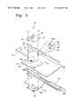
- FIG. 3is an enlarged perspective view for illustrating parts of FIG. 2 related to the mounting structure of a semiconductor device module, in accordance with the principles of the present invention
- FIGS. 4A to 4 Care the cross sectional views of the system body for illustrating the procedure of mounting a semiconductor device module, in accordance with the principles of the present invention.
- FIG. 5is a cross sectional view of the system body for illustrating a semiconductor device module completely mounted on the motherboard, in accordance with the principles of the present invention.
- a semiconductor device module 130is mounted in a motherboard 110 by means of four fasteners 120 , which are respectively held by nuts 140 on the lower surface of the board 110 .
- an additional toolis required for fixing the nuts 140 to the fasteners 120 , risking the lower surface ofthe motherboard to injury.
- such mounting proceduremakes the assembling of the parts difficult.
- an additional heat drain structure(not shown) is required to dissipate the heat generated from the chip set 150 , for example, 440 BX CHIP, mounted near the semiconductor device module 130 .
- the same reference numeralsare used throughout the attached drawings to represent same functional parts.
- the computer system 10includes a display panel (not shown) hinged to a system body 12 .
- the system body 12includes a bottom housing part 12 b and top housing part 12 a enclosing the motherboard 14 , electronic card assemblies (not shown), the semiconductor device module 20 and the rear bracket 40 .
- a keyboard 50is mounted on a keyboard seat 13 formed on the upper surface of the system body 12 .
- the keyboard seat 13is provided with an opening 13 a through which the semiconductor device module 20 is mounted on the motherboard 14 . To this end, it is desirable that the part of the motherboard 14 on which the semiconductor device module 20 is positioned so as to face the opening 13 a.
- every comer of the semiconductor device module 20is provided with a first hole 22 , and the lower surface of the module 20 with a first connector 24 .
- the motherboard 14is provided with a second connector 16 connected with the first connector 24 , and second holes 14 a corresponding with the first holes 22 .
- the chip set 18is mounted on the lower surface of the motherboard 14 so as to be opposed to the module 20 .
- the fasteners 30are used to fix the semiconductor device module 20 to the motherboard 14 .
- Each of the fasteners 30is cylindrically shaped to have a first fixing part 32 , second fixing part 34 and middle support 36 , as shown in FIG. 3 .
- the first fixing part 32 of the fastener 30is passed through the second hole 14 a of the motherboard 14 , fixed into a boss 44 formed in the rear bracket 40 below the motherboard 20 , as shown in FIGS. 2 and 3.
- the second fixing part 34 positioned opposite to the first fixing part 32is inserted upwardly into the first hole 22 of the semiconductor device module 20 .
- the upper end of the second fixing part 34is provided with a female threaded hole 34 a with which the screw 70 is engaged through the first hole 22 of the semiconductor device module 20 .
- the end of the second fixing part 34is provided with a central slot to receive the tip of a screwdriver, by which the fastener 30 may be fixed or released to or from the boss 44 of the rear bracket 40 .
- the middle support 36is laterally protruded between the first fixing part 32 and second fixing part 34 so as to support the semiconductor device module 20 with a space from the motherboard 14 .
- the rear bracket 40is attached on one side of the bottom housing part 12 b to support a plurality of peripheral ports 14 b installed on the motherboard 14 connected with various peripheral devices. Preferably, one side of the rear bracket 40 is exposed to the outside of the bottom housing part so as to prevent electromagnetic interferences and dissipate the heat generated from the chip set 18 .
- the rear bracket 40has an extension plate 42 placed beneath the motherboard to face the chip set 18 .
- the bosses 44are formed on the extension plate 42 so as to respectively hold the end parts of the first fixing parts 32 of the fasteners 30 .
- the extension plate 42has a heat sink pad 46 facing the chip set 18 in order to effectively drain the heat of the chip set 18 through the rear bracket 40 .
- the rearbracket 40is firstly mounted on the bottom and side of the bottom housing part 12 b .
- the motherboard 14is attached to the extension part 42 with screw 70 , so that the chip set 18 mounted on the lower surface of the motherboard is contacted with the heat sink pad 46 , as shown in FIG. 4 b .
- the heat of the chip set 18is dissipated through the heat sink pad 46 to the rear bracket 40 to the outside of the housing.
- the first fixing parts 32 of the fasteners 30are inserted through the second holes 14 a of the motherboard 14 , fixed into the respective bosses 44 of the extension part 42 .
- the first connector 24 of the semiconductor device module 20is electrically connected with the second connector 16 of the motherboard 14 .
- the second fixing parts 34 of the fasteners 30are inserted into the respective first holes 22 of the semiconductor device module 20 .
- the middle supports 36 of the fasteners 30support the lower surface of the module 20 .
- the heat sink member 60includes a heat sink 62 contacting the upper surface of the semiconductor device module 20 and a heat dissipation plate 64 contacting the detachable keyboard 50 .
Landscapes
- Engineering & Computer Science (AREA)
- Microelectronics & Electronic Packaging (AREA)
- Theoretical Computer Science (AREA)
- Human Computer Interaction (AREA)
- Physics & Mathematics (AREA)
- General Engineering & Computer Science (AREA)
- General Physics & Mathematics (AREA)
- Cooling Or The Like Of Electrical Apparatus (AREA)
Abstract
Description
Claims (20)
Applications Claiming Priority (2)
| Application Number | Priority Date | Filing Date | Title |
|---|---|---|---|
| KR10-1998-0043526AKR100521339B1 (en) | 1998-10-17 | 1998-10-17 | Mounting structure of semiconductor device module for a computer system |
| KR98-43526 | 1998-10-17 |
Publications (1)
| Publication Number | Publication Date |
|---|---|
| US6226179B1true US6226179B1 (en) | 2001-05-01 |
Family
ID=19554413
Family Applications (1)
| Application Number | Title | Priority Date | Filing Date |
|---|---|---|---|
| US09/419,298Expired - LifetimeUS6226179B1 (en) | 1998-10-17 | 1999-10-15 | Mounting structure of a semiconductor device module for a computer system |
Country Status (2)
| Country | Link |
|---|---|
| US (1) | US6226179B1 (en) |
| KR (1) | KR100521339B1 (en) |
Cited By (22)
| Publication number | Priority date | Publication date | Assignee | Title |
|---|---|---|---|---|
| US6377454B1 (en)* | 1999-04-28 | 2002-04-23 | Fujitsu Limited | Heat conducting apparatus and electronic apparatus having the same |
| US20020172022A1 (en)* | 1999-07-15 | 2002-11-21 | Incep Technologies, Inc. | Method and apparatus for providing power to a microprocessor with integrated thermal and EMI management |
| USD466094S1 (en) | 2002-01-30 | 2002-11-26 | Miranda Technologies Inc. | Circuit board |
| US6487995B2 (en)* | 2000-11-30 | 2002-12-03 | Detroit Diesel Corporation | Engine controller and enclosure assembly |
| US20030057548A1 (en)* | 1999-07-15 | 2003-03-27 | Incep Technologies, Inc. | Integrated power delivery and cooling system for high power microprocessors |
| US6542366B2 (en)* | 2000-12-28 | 2003-04-01 | Gateway, Inc. | Circuit board support |
| US6574101B2 (en)* | 2000-05-12 | 2003-06-03 | Fujitsu Limited | Portable electronic device capable of efficiently cooling heat-generation electronic component |
| US20030214800A1 (en)* | 1999-07-15 | 2003-11-20 | Dibene Joseph Ted | System and method for processor power delivery and thermal management |
| US6724620B1 (en) | 2002-10-31 | 2004-04-20 | Hewlett-Packard Development Company, L.P. | Low profile tool-less mounting adapter |
| US20040179345A1 (en)* | 2003-02-28 | 2004-09-16 | Kabushiki Kaisha Toshiba | Electronic apparatus having removable circuit board to connect expansion card |
| US6847529B2 (en) | 1999-07-15 | 2005-01-25 | Incep Technologies, Inc. | Ultra-low impedance power interconnection system for electronic packages |
| US20050078460A1 (en)* | 2003-10-14 | 2005-04-14 | Richard Owen T. | Printed circuit board assembly mounting system |
| US20050185380A1 (en)* | 2004-02-24 | 2005-08-25 | Wen-Shu Lee | Dissipation structure and method for backlight inverter |
| US20060044764A1 (en)* | 2004-08-26 | 2006-03-02 | Asustek Computer Inc. | Auxiliary supporting structure of circuit board and assembling method for the same |
| US7167379B2 (en) | 2001-02-16 | 2007-01-23 | Dibene Ii Joseph T | Micro-spring interconnect systems for low impedance high power applications |
| US7336496B1 (en)* | 2006-09-14 | 2008-02-26 | Inventec Corporation | Fixing structure for computer mainboard |
| US20080187407A1 (en)* | 2007-02-02 | 2008-08-07 | Compal Electronics, Inc. | Fastening structure for reducing surface temperature of housing |
| USD637566S1 (en)* | 2010-08-10 | 2011-05-10 | Taymac Corporation | Electrical receptacle circuit board |
| EP2802196A3 (en)* | 2013-05-07 | 2015-04-01 | Honeywell International Inc. | Radiation shield standoff |
| CN111315177A (en)* | 2020-03-07 | 2020-06-19 | 北京金晟达生物电子科技有限公司 | Protective shell for mounting printed circuit board |
| US11195779B2 (en) | 2019-08-09 | 2021-12-07 | Raytheon Company | Electronic module for motherboard |
| US20220087072A1 (en)* | 2020-09-16 | 2022-03-17 | Kioxia Corporation | Semiconductor storage device |
Citations (23)
| Publication number | Priority date | Publication date | Assignee | Title |
|---|---|---|---|---|
| US4084242A (en) | 1976-11-10 | 1978-04-11 | Pitney-Bowes, Inc. | Electronic postage weighing scale |
| US4658332A (en)* | 1983-04-04 | 1987-04-14 | Raytheon Company | Compliant layer printed circuit board |
| US4748495A (en) | 1985-08-08 | 1988-05-31 | Dypax Systems Corporation | High density multi-chip interconnection and cooling package |
| EP0279996A1 (en)* | 1985-06-24 | 1988-08-31 | Digital Equipment Corporation | Multiple chip interconnection system and package |
| US5074799A (en)* | 1991-03-27 | 1991-12-24 | Amp Incorporated | Gel connector of laminar construction |
| US5287617A (en) | 1992-08-11 | 1994-02-22 | Advanced Interconnections Corporation | Apparatus for extracting an integrated circuit package installed in a socket on a circuit board |
| US5369879A (en) | 1992-06-05 | 1994-12-06 | Eaton Corporation | Method of mounting a semiconductor device to a heat sink |
| US5424913A (en)* | 1994-01-11 | 1995-06-13 | Dell Usa, L.P. | Heat sink/component access door for portable computers |
| US5430609A (en)* | 1993-09-02 | 1995-07-04 | Kikinis; Dan | Microprocessor cooling in a portable computer |
| US5444298A (en)* | 1993-02-04 | 1995-08-22 | Intel Corporation | Voltage converting integrated circuit package |
| US5473510A (en)* | 1994-03-25 | 1995-12-05 | Convex Computer Corporation | Land grid array package/circuit board assemblies and methods for constructing the same |
| US5526229A (en)* | 1992-02-26 | 1996-06-11 | Seiko Epson Corporation | Temperature control for add-on electronic devices |
| US5619399A (en)* | 1995-02-16 | 1997-04-08 | Micromodule Systems, Inc. | Multiple chip module mounting assembly and computer using same |
| US5703753A (en)* | 1995-02-16 | 1997-12-30 | Micromodule Systems Inc. | Mounting assembly for multiple chip module with more than one substrate and computer using same |
| US5705932A (en) | 1995-10-10 | 1998-01-06 | Xilinx, Inc. | System for expanding space provided by test computer to test multiple integrated circuits simultaneously |
| US5880930A (en)* | 1997-06-18 | 1999-03-09 | Silicon Graphics, Inc. | Electromagnetic interference shielding enclosure and heat sink with compression coupling mechanism |
| US5919359A (en) | 1997-11-11 | 1999-07-06 | Bisseker; Robin | Portable pool skimmer |
| US5926370A (en) | 1998-10-29 | 1999-07-20 | Hewlett-Packard Company | Method and apparatus for a modular integrated apparatus for multi-function components |
| JPH11273816A (en)* | 1998-03-20 | 1999-10-08 | Fujitsu Ltd | Semiconductor parts and semiconductor mounting equipment |
| US6058012A (en)* | 1996-08-26 | 2000-05-02 | Compaq Computer Corporation | Apparatus, method and system for thermal management of an electronic system having semiconductor devices |
| US6075700A (en)* | 1999-02-02 | 2000-06-13 | Compaq Computer Corporation | Method and system for controlling radio frequency radiation in microelectronic packages using heat dissipation structures |
| US6084178A (en)* | 1998-02-27 | 2000-07-04 | Hewlett-Packard Company | Perimeter clamp for mounting and aligning a semiconductor component as part of a field replaceable unit (FRU) |
| US6144559A (en)* | 1999-04-08 | 2000-11-07 | Agilent Technologies | Process for assembling an interposer to probe dense pad arrays |
Family Cites Families (5)
| Publication number | Priority date | Publication date | Assignee | Title |
|---|---|---|---|---|
| JP2825353B2 (en)* | 1991-01-17 | 1998-11-18 | 三菱電機株式会社 | Control device with shielding function |
| SE509594C2 (en)* | 1996-01-26 | 1999-02-15 | Sandvik Ab | Indexing of inserts |
| US5766022A (en)* | 1996-05-21 | 1998-06-16 | International Business Machines Corporation | Electrical assembly |
| KR19990010812U (en)* | 1997-08-30 | 1999-03-25 | 송기선 | Chip type L.D.M heat sink assembly structure |
| KR100530869B1 (en)* | 1998-04-24 | 2006-02-28 | 삼성전자주식회사 | Computer system with the apparatus for mounting semiconductor device module on board |
- 1998
- 1998-10-17KRKR10-1998-0043526Apatent/KR100521339B1/ennot_activeExpired - Fee Related
- 1999
- 1999-10-15USUS09/419,298patent/US6226179B1/ennot_activeExpired - Lifetime
Patent Citations (23)
| Publication number | Priority date | Publication date | Assignee | Title |
|---|---|---|---|---|
| US4084242A (en) | 1976-11-10 | 1978-04-11 | Pitney-Bowes, Inc. | Electronic postage weighing scale |
| US4658332A (en)* | 1983-04-04 | 1987-04-14 | Raytheon Company | Compliant layer printed circuit board |
| EP0279996A1 (en)* | 1985-06-24 | 1988-08-31 | Digital Equipment Corporation | Multiple chip interconnection system and package |
| US4748495A (en) | 1985-08-08 | 1988-05-31 | Dypax Systems Corporation | High density multi-chip interconnection and cooling package |
| US5074799A (en)* | 1991-03-27 | 1991-12-24 | Amp Incorporated | Gel connector of laminar construction |
| US5526229A (en)* | 1992-02-26 | 1996-06-11 | Seiko Epson Corporation | Temperature control for add-on electronic devices |
| US5369879A (en) | 1992-06-05 | 1994-12-06 | Eaton Corporation | Method of mounting a semiconductor device to a heat sink |
| US5287617A (en) | 1992-08-11 | 1994-02-22 | Advanced Interconnections Corporation | Apparatus for extracting an integrated circuit package installed in a socket on a circuit board |
| US5444298A (en)* | 1993-02-04 | 1995-08-22 | Intel Corporation | Voltage converting integrated circuit package |
| US5430609A (en)* | 1993-09-02 | 1995-07-04 | Kikinis; Dan | Microprocessor cooling in a portable computer |
| US5424913A (en)* | 1994-01-11 | 1995-06-13 | Dell Usa, L.P. | Heat sink/component access door for portable computers |
| US5473510A (en)* | 1994-03-25 | 1995-12-05 | Convex Computer Corporation | Land grid array package/circuit board assemblies and methods for constructing the same |
| US5619399A (en)* | 1995-02-16 | 1997-04-08 | Micromodule Systems, Inc. | Multiple chip module mounting assembly and computer using same |
| US5703753A (en)* | 1995-02-16 | 1997-12-30 | Micromodule Systems Inc. | Mounting assembly for multiple chip module with more than one substrate and computer using same |
| US5705932A (en) | 1995-10-10 | 1998-01-06 | Xilinx, Inc. | System for expanding space provided by test computer to test multiple integrated circuits simultaneously |
| US6058012A (en)* | 1996-08-26 | 2000-05-02 | Compaq Computer Corporation | Apparatus, method and system for thermal management of an electronic system having semiconductor devices |
| US5880930A (en)* | 1997-06-18 | 1999-03-09 | Silicon Graphics, Inc. | Electromagnetic interference shielding enclosure and heat sink with compression coupling mechanism |
| US5919359A (en) | 1997-11-11 | 1999-07-06 | Bisseker; Robin | Portable pool skimmer |
| US6084178A (en)* | 1998-02-27 | 2000-07-04 | Hewlett-Packard Company | Perimeter clamp for mounting and aligning a semiconductor component as part of a field replaceable unit (FRU) |
| JPH11273816A (en)* | 1998-03-20 | 1999-10-08 | Fujitsu Ltd | Semiconductor parts and semiconductor mounting equipment |
| US5926370A (en) | 1998-10-29 | 1999-07-20 | Hewlett-Packard Company | Method and apparatus for a modular integrated apparatus for multi-function components |
| US6075700A (en)* | 1999-02-02 | 2000-06-13 | Compaq Computer Corporation | Method and system for controlling radio frequency radiation in microelectronic packages using heat dissipation structures |
| US6144559A (en)* | 1999-04-08 | 2000-11-07 | Agilent Technologies | Process for assembling an interposer to probe dense pad arrays |
Cited By (33)
| Publication number | Priority date | Publication date | Assignee | Title |
|---|---|---|---|---|
| US6377454B1 (en)* | 1999-04-28 | 2002-04-23 | Fujitsu Limited | Heat conducting apparatus and electronic apparatus having the same |
| US20050277310A1 (en)* | 1999-07-15 | 2005-12-15 | Molex Incorporated | System and method for processor power delivery and thermal management |
| US6847529B2 (en) | 1999-07-15 | 2005-01-25 | Incep Technologies, Inc. | Ultra-low impedance power interconnection system for electronic packages |
| US20070268677A1 (en)* | 1999-07-15 | 2007-11-22 | Molex Incorporated | System and method for processor power delivery and thermal management |
| US20030057548A1 (en)* | 1999-07-15 | 2003-03-27 | Incep Technologies, Inc. | Integrated power delivery and cooling system for high power microprocessors |
| US20070004240A1 (en)* | 1999-07-15 | 2007-01-04 | Molex Incorporated | System and method for processor power delivery and thermal management |
| US20020172022A1 (en)* | 1999-07-15 | 2002-11-21 | Incep Technologies, Inc. | Method and apparatus for providing power to a microprocessor with integrated thermal and EMI management |
| US20030214800A1 (en)* | 1999-07-15 | 2003-11-20 | Dibene Joseph Ted | System and method for processor power delivery and thermal management |
| US7881072B2 (en) | 1999-07-15 | 2011-02-01 | Molex Incorporated | System and method for processor power delivery and thermal management |
| US6801431B2 (en)* | 1999-07-15 | 2004-10-05 | Incep Technologies, Inc. | Integrated power delivery and cooling system for high power microprocessors |
| US6947293B2 (en)* | 1999-07-15 | 2005-09-20 | Incep Technologies | Method and apparatus for providing power to a microprocessor with integrated thermal and EMI management |
| US6574101B2 (en)* | 2000-05-12 | 2003-06-03 | Fujitsu Limited | Portable electronic device capable of efficiently cooling heat-generation electronic component |
| US6487995B2 (en)* | 2000-11-30 | 2002-12-03 | Detroit Diesel Corporation | Engine controller and enclosure assembly |
| US6542366B2 (en)* | 2000-12-28 | 2003-04-01 | Gateway, Inc. | Circuit board support |
| US7167379B2 (en) | 2001-02-16 | 2007-01-23 | Dibene Ii Joseph T | Micro-spring interconnect systems for low impedance high power applications |
| USD466094S1 (en) | 2002-01-30 | 2002-11-26 | Miranda Technologies Inc. | Circuit board |
| US6724620B1 (en) | 2002-10-31 | 2004-04-20 | Hewlett-Packard Development Company, L.P. | Low profile tool-less mounting adapter |
| US20040179345A1 (en)* | 2003-02-28 | 2004-09-16 | Kabushiki Kaisha Toshiba | Electronic apparatus having removable circuit board to connect expansion card |
| US7012804B2 (en)* | 2003-02-28 | 2006-03-14 | Kabushiki Kaisha Toshiba | Electronic apparatus having removable circuit board to connect expansion card |
| US20050078460A1 (en)* | 2003-10-14 | 2005-04-14 | Richard Owen T. | Printed circuit board assembly mounting system |
| US20050185380A1 (en)* | 2004-02-24 | 2005-08-25 | Wen-Shu Lee | Dissipation structure and method for backlight inverter |
| US20060044764A1 (en)* | 2004-08-26 | 2006-03-02 | Asustek Computer Inc. | Auxiliary supporting structure of circuit board and assembling method for the same |
| US7352586B2 (en)* | 2004-08-26 | 2008-04-01 | Asustek Computer Inc. | Auxiliary supporting structure of circuit board and assembling method for the same |
| US20080068808A1 (en)* | 2006-09-14 | 2008-03-20 | Inventec Corporation | Fixing structure for computer mainboard |
| US7336496B1 (en)* | 2006-09-14 | 2008-02-26 | Inventec Corporation | Fixing structure for computer mainboard |
| US20080187407A1 (en)* | 2007-02-02 | 2008-08-07 | Compal Electronics, Inc. | Fastening structure for reducing surface temperature of housing |
| USD637566S1 (en)* | 2010-08-10 | 2011-05-10 | Taymac Corporation | Electrical receptacle circuit board |
| EP2802196A3 (en)* | 2013-05-07 | 2015-04-01 | Honeywell International Inc. | Radiation shield standoff |
| US9521789B2 (en) | 2013-05-07 | 2016-12-13 | Honeywell International, Inc. | Radiation shield standoff |
| US11195779B2 (en) | 2019-08-09 | 2021-12-07 | Raytheon Company | Electronic module for motherboard |
| CN111315177A (en)* | 2020-03-07 | 2020-06-19 | 北京金晟达生物电子科技有限公司 | Protective shell for mounting printed circuit board |
| US20220087072A1 (en)* | 2020-09-16 | 2022-03-17 | Kioxia Corporation | Semiconductor storage device |
| US11744046B2 (en)* | 2020-09-16 | 2023-08-29 | Kioxia Corporation | Semiconductor storage device |
Also Published As
| Publication number | Publication date |
|---|---|
| KR100521339B1 (en) | 2005-12-21 |
| KR20000026140A (en) | 2000-05-15 |
Similar Documents
| Publication | Publication Date | Title |
|---|---|---|
| US6226179B1 (en) | Mounting structure of a semiconductor device module for a computer system | |
| US5619399A (en) | Multiple chip module mounting assembly and computer using same | |
| US5880929A (en) | Heat exchanger system for cooling a hinged computing device | |
| US6223815B1 (en) | Cooling unit for cooling a heat-generating component and electronic apparatus having the cooling unit | |
| US7272001B2 (en) | External conductive heat dissipating device for microcomputers | |
| US5969940A (en) | Mechanical structure of information processing device | |
| US5966289A (en) | Electronic device securement system | |
| US5703753A (en) | Mounting assembly for multiple chip module with more than one substrate and computer using same | |
| US5671120A (en) | Passively cooled PC heat stack having a heat-conductive structure between a CPU on a motherboard and a heat sink | |
| US5430609A (en) | Microprocessor cooling in a portable computer | |
| US5973920A (en) | Heat frame for portable computer | |
| US8520393B2 (en) | Apparatuses and methods for dissipating heat from a computer component | |
| US20050083660A1 (en) | Power supply without cooling fan | |
| US20020105785A1 (en) | Circuit board support | |
| US20050108877A1 (en) | Apparatus and method for coupling a thermal dissipation device to an electronic substrate | |
| US7212408B2 (en) | Multi-slot socket for mounting integrated circuits on circuit board | |
| US6111746A (en) | Computer processor module ground/EMI-shield spring clip and method | |
| JPH07101780B2 (en) | Planar board support device | |
| EP0852350A2 (en) | A computer system having plug-in type modules | |
| US7190590B2 (en) | Holding fixture, component mounting method, electronic circuit unit and electronic apparatus | |
| KR20000021171U (en) | A radiation device for using portable computer | |
| US6934157B2 (en) | Universal heat sink retention module frame | |
| KR100313310B1 (en) | Portable computer with the dissipating apparatus of electronic system | |
| JP2003208238A (en) | Information processing equipment | |
| US5978873A (en) | Computer system including right angle processor and add-on card connectors |
Legal Events
| Date | Code | Title | Description |
|---|---|---|---|
| AS | Assignment | Owner name:SAMSUNG ELECTRONICS CO., LTD., A CORP. OF KOREA, K Free format text:ASSIGNMENT OF ASSIGNORS INTEREST;ASSIGNOR:LEE, SUNG-BAE;REEL/FRAME:010325/0613 Effective date:19991015 | |
| STCF | Information on status: patent grant | Free format text:PATENTED CASE | |
| FEPP | Fee payment procedure | Free format text:PAYOR NUMBER ASSIGNED (ORIGINAL EVENT CODE: ASPN); ENTITY STATUS OF PATENT OWNER: LARGE ENTITY | |
| FPAY | Fee payment | Year of fee payment:4 | |
| FPAY | Fee payment | Year of fee payment:8 | |
| FEPP | Fee payment procedure | Free format text:PAYOR NUMBER ASSIGNED (ORIGINAL EVENT CODE: ASPN); ENTITY STATUS OF PATENT OWNER: LARGE ENTITY Free format text:PAYER NUMBER DE-ASSIGNED (ORIGINAL EVENT CODE: RMPN); ENTITY STATUS OF PATENT OWNER: LARGE ENTITY | |
| AS | Assignment | Owner name:TRANSPACIFIC AVARTAR, LLC, DELAWARE Free format text:ASSIGNMENT OF ASSIGNORS INTEREST;ASSIGNOR:SAMSUNG ELECTRONICS CO., LTD.;REEL/FRAME:022034/0236 Effective date:20081030 | |
| FEPP | Fee payment procedure | Free format text:PAYOR NUMBER ASSIGNED (ORIGINAL EVENT CODE: ASPN); ENTITY STATUS OF PATENT OWNER: LARGE ENTITY Free format text:PAYER NUMBER DE-ASSIGNED (ORIGINAL EVENT CODE: RMPN); ENTITY STATUS OF PATENT OWNER: LARGE ENTITY | |
| FPAY | Fee payment | Year of fee payment:12 |