US6226165B1 - System and method for securing a computer system - Google Patents
System and method for securing a computer systemDownload PDFInfo
- Publication number
- US6226165B1 US6226165B1US09/291,540US29154099AUS6226165B1US 6226165 B1US6226165 B1US 6226165B1US 29154099 AUS29154099 AUS 29154099AUS 6226165 B1US6226165 B1US 6226165B1
- Authority
- US
- United States
- Prior art keywords
- computer system
- signal line
- electrically conductive
- conductive signal
- detecting
- Prior art date
- Legal status (The legal status is an assumption and is not a legal conclusion. Google has not performed a legal analysis and makes no representation as to the accuracy of the status listed.)
- Expired - Lifetime
Links
Images


Classifications
- E—FIXED CONSTRUCTIONS
- E05—LOCKS; KEYS; WINDOW OR DOOR FITTINGS; SAFES
- E05B—LOCKS; ACCESSORIES THEREFOR; HANDCUFFS
- E05B73/00—Devices for locking portable objects against unauthorised removal; Miscellaneous locking devices
- E05B73/0082—Devices for locking portable objects against unauthorised removal; Miscellaneous locking devices for office machines, e.g. PC's, portable computers, typewriters, calculators
- G—PHYSICS
- G06—COMPUTING OR CALCULATING; COUNTING
- G06F—ELECTRIC DIGITAL DATA PROCESSING
- G06F1/00—Details not covered by groups G06F3/00 - G06F13/00 and G06F21/00
- G06F1/16—Constructional details or arrangements
- G06F1/1613—Constructional details or arrangements for portable computers
- G06F1/1632—External expansion units, e.g. docking stations
- G—PHYSICS
- G06—COMPUTING OR CALCULATING; COUNTING
- G06F—ELECTRIC DIGITAL DATA PROCESSING
- G06F21/00—Security arrangements for protecting computers, components thereof, programs or data against unauthorised activity
- G06F21/70—Protecting specific internal or peripheral components, in which the protection of a component leads to protection of the entire computer
- G06F21/86—Secure or tamper-resistant housings
- E—FIXED CONSTRUCTIONS
- E05—LOCKS; KEYS; WINDOW OR DOOR FITTINGS; SAFES
- E05B—LOCKS; ACCESSORIES THEREFOR; HANDCUFFS
- E05B73/00—Devices for locking portable objects against unauthorised removal; Miscellaneous locking devices
- E05B73/0005—Devices for locking portable objects against unauthorised removal; Miscellaneous locking devices using chains, cables or the like
Definitions
- the disclosures hereinrelate in general to computer systems and in particular to an information processing system and method for securing operation of a computer system.
- a portable computerIn comparison to a desktop computer, a portable computer is more subject to theft under some circumstances. Accordingly, various security features have been developed to deter such theft. At least some of those features are mechanical.
- a mechanical security devicee.g. a hook latch protrusion
- mechanically secures (e.g. holds) the portable computer to a docking statione.g. holds) the portable computer to a docking station.
- the mechanical security deviceis subject to defeat by mechanically prying the portable computer loose from the docking station.
- the portable computer's securityis dependent on increased strength of a material, such as plastic or metal, that houses components of the portable computer or docking station. Nevertheless, practical limits (on the extent to which the material's strength may be increased) are imposed by factors such as cost and weight.
- a needhas arisen for a system and method for securing a computer system, in which various shortcomings of previous techniques are overcome. More particularly, a need has arisen for a system and method for securing a computer system, in which the computer system's security is less dependent on increased strength of material that houses components of the computer system.
- One embodimentaccordingly, provides for a housing for components of a computer system.
- a portion of the housingincludes a material which includes circuitry for detecting a physical break in the material. In response to the physical break, the circuitry disables an operation of the computer system.
- a principal advantage of this embodimentis that (a) various shortcomings of previous techniques are overcome, and (b) the computer system's security is less dependent on increased strength of material that houses components of the computer system.
- FIG. 1is a block diagram of a computer system according to the illustrative embodiment.
- FIG. 2is a block diagram of a computer of the computer system of FIG. 1 .
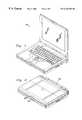
- FIG. 3is a first perspective view of a portable embodiment of the computer system of FIG. 1 .
- FIG. 4is a second perspective view of the portable embodiment of FIG. 3 .
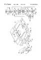
- FIG. 5is a perspective view of a docking station as it secures the portable embodiment of FIG. 3 .
- FIG. 6is a first cross-sectional view of the docking station of FIG. 5 as it secures the portable embodiment of FIG. 3 .
- FIG. 7is a second cross-sectional view of the docking station of FIG. 5 as it secures the portable embodiment of FIG. 3 .
- FIG. 8is a magnified view of a portion of FIG. 7 .
- FIG. 9is a third cross-sectional view of the docking station of FIG. 5 and the portable embodiment of FIG. 3 .
- FIG. 10is a flowchart of operation of the computer of FIG. 2 in securing the computer system of FIG. 1 .
- FIG. 1is a block diagram of a computer system, indicated generally at 100 , according to the illustrative embodiment.
- System 100includes input devices 104 , a display device 106 , and a computer 102 for executing processes and performing operations (e.g. communicating information) in response thereto as discussed further hereinbelow.
- system 100is an IBM-compatible portable personal computer (“PC”) that executes Microsoft Windows 95 operating system (“OS”) software. All Microsoft products identified herein are available from Microsoft Corporation, One Microsoft Way, Redmond, Wash. 98052-6399, telephone (425) 882-8080.
- PCportable personal computer
- OSMicrosoft Windows 95 operating system
- Computer 102is connected to input devices 104 , display device 106 and a print device 108 .
- Print device 108is, for example, a conventional electronic printer or plotter.
- computer 102includes internal speakers for outputting audio signals. In an alternative embodiment, the speakers are external to computer 102 .
- system 100includes (a) a first computer-readable medium (or apparatus) 110 which is a floppy diskette and (b) a second computer-readable medium (or apparatus) 111 which is a computer hard disk.
- a human user 112 and computer 102operate in association with one another. For example, in response to signals from computer 102 , display device 106 displays visual images, and user 112 views such visual images. Also, in response to signals from computer 102 , print device 108 prints visual images on paper, and user 112 views such visual images. Further, user 112 operates input devices 104 in order to output information to computer 102 , and computer 102 receives such information from input devices 104 .
- Input devices 104include, for example, a conventional electronic keyboard and a pointing device such as a conventional electronic “mouse”, rollerball or light pen.
- User 112operates the keyboard to output alphanumeric text information to computer 102 , and computer 102 receives such alphanumeric text information from the keyboard.
- User 112operates the pointing device to output cursor-control information to computer 102 , and computer 102 receives such cursor-control information from the pointing device.
- a network 114includes a network local area network (“LAN”) control manager server computer (“LCM”).
- LCMcontrol manager server computer
- computer 102For communicating with (i.e. outputting information to, and receiving information from) network 114 (including the LCM), computer 102 includes a network interface card (“NIC”) which is yet another type of computer-readable medium (or apparatus) connected to computer 102 .
- LANlocal area network
- NICnetwork interface card
- FIG. 2is a block diagram of computer 102 , which is formed by various electronic circuitry components.
- such electronic circuitry componentsreside on a system printed wire assembly (“PWA”).
- the electronic circuitry components of computer 102include: a central processing unit (“CPU”) 202 for executing and otherwise processing instructions, input/output (“I/O”) controller circuitry 204 , a basic input/output system (“BIOS”) electrically erasable programmable read only memory device (“EEPROM”) 206 for storing firmware, a memory 208 such as random access memory device (“RAM”) and read only memory device (“ROM”) for storing information (e.g.
- CPUcentral processing unit
- I/Oinput/output
- BIOSbasic input/output system
- EEPROMelectrically erasable programmable read only memory device
- RAMrandom access memory device
- ROMread only memory device
- computer 102may include various other electronic circuitry components that, for clarity, are not shown in FIG. 2 .
- I/O controller circuitry 210is coupled to I/O devices 216 .
- I/O devices 216include, for example, input devices 104 , display device 106 , print device 108 , floppy diskette 110 , hard disk 111 , and the network interface card (“NIC”) discussed hereinabove in connection with FIG. 1 .
- I/O controller circuitry 210includes controller circuitry for operating I/O devices 216 , reading information from I/O devices 216 , and writing information to I/O devices 216 .
- Computer 102operates its various components (e.g. I/O controller circuitry 210 ) in response to information stored by BIOS 206 .
- I/O controller circuitry 210outputs various interrupt requests (“IRQs”), and computer 102 reacts to such IRQs in response to information stored by BIOS 206 .
- IRQsinterrupt requests
- BIOS 206one or more components of computer 102 may be effectively disabled, so that computer 102 operates without reference to such components. In such a situation where a component is disabled, computer 102 would not react to an IRQ from such a disabled component, and computer 102 would not allocate resources to such a disabled component.
- computer 102includes power circuitry 216 coupled through a power bus 218 to each of CPU 202 , I/O controller circuitry 204 , BIOS 206 , memory 208 and logic 210 .
- Power circuitry 216receives power from a power source, converts such power into a suitable form, and distributes such converted power through power bus 218 . Accordingly, power circuitry 216 includes circuitry such as pull-up resistors.
- power circuitry 216is further connected to I/O controller circuitry 204 through an electrically conductive signal line 220 , such as a semiconductor device, a small printed circuit board (“PCB”), a metal wire, or other electrically conductive device or material.
- line 220is substantially difficult for a human thief to repair after line 220 physically breaks. As shown in FIG. 2, a portion of line 220 extends away from the PWA. Such portion is identified by dashed enclosure 222 .
- the programming of BIOS 206 and the design of I/O controller circuitry 204are suitable to: (a) enable booting and normal operation of computer 102 , so long as line 220 remains intact to form a closed circuit between power circuitry 216 and I/O controller circuitry 204 ; and (b) disable booting and normal operation of computer 102 if line 220 (e.g. portion 222 ) is broken to form an open circuit between power circuitry 216 and I/O controller circuitry 204 .
- electronic circuitry componentse.g. BIOS 206 and I/O controller circuitry 204
- BIOS 206 and I/O controller circuitry 204of computer 102 detect a physical break in line 220 and, in response to the physical break, disable an operation of system 100 .
- FIG. 3is a first perspective view of a portable embodiment of system 100 .
- the portable embodiment of system 100is a laptop computer or notebook computer.
- the portable embodiment of system 100is a palmtop computer device or other handheld computer system.
- FIG. 4is a second perspective view of the portable embodiment of system 100 . As shown in FIG. 4, a rear portion of the portable embodiment includes receptacles 402 and 404 .
- FIG. 5is a perspective view of a docking station 502 device as it secures the portable embodiment of system 100 .
- Docking station 502includes a surface 504 for supporting the portable embodiment of system 100 , as shown in FIG. 5.
- a handle 506 of docking station 502is operable by user 112 and is movable along the direction of line 508 between an eject position, an unlock position, and a lock position.
- Docking station 502includes a bus connector 509 for mechanically engaging with receptacle 402 (FIG. 4) at the rear portion of system 100 , in order to electrically connect docking station 502 to system 100 and thereby enable communication of information between them. Also, docking station 502 includes a first security device 510 having a hook latch protrusion that is selectively movable into and out of mechanical engagement with receptacle 404 (FIG. 4) at the rear portion of system 100 , in order to mechanically secure system 100 to docking station 502 .
- docking station 502includes a second security device 512 having a hook latch protrusion that is selectively movable into and out of mechanical engagement with a bottom receptacle of system 100 , in order to mechanically secure system 100 to docking station 502 .
- engaging (or engagement of) A with Bare likewise intended to mean engaging (or engagement of) B with A, so that such engaging (or engagement) is of A and B with one another (i.e. engaging (or engagement) between A and B).
- the hook latch protrusions of security devices 510 and 512are selectively movable in response to a movement of handle 506 between the eject position, the unlock position, and the lock position.
- system 100is seated on docking station 502 with handle 506 in the unlock position.
- user 112operates handle 506 by moving it to the lock position.
- the hook latch protrusions of security devices 510 and 512move into mechanical engagement with system 100 .
- physical disconnection of system 100 from docking station 502e.g. physical removal of system 100 away from docking station 502
- user 112may (a) insert a locking device 514 into a receptacle 516 of docking station 502 , (b) insert a key 518 into a receptacle 520 of locking device 514 , (c) rotate key 518 in a clockwise direction, and (d) then remove key 518 from locking device 514 .
- user 112operates locking device 514 to lock docking station 502 into a substantially fixed position, so that handle 506 is substantially fixed in the lock position and ceases being movable to the eject or unlock positions (i.e. ceases being operable (by user 112 ) to mechanically release system 100 from docking station 502 ).
- locking device 514is for disabling mechanical release of system 100 from docking station 502 , so that physical disconnection of system 100 from docking station 502 (e.g. physical removal of system 100 away from docking station 502 ) involves physically breaking system 100 by application of a predetermined physical force on system 100 . Moreover, in that manner, locking device 514 secures docking station 502 through a connector device (e.g. cable 522 in FIG. 5) which connects docking station 502 to a relatively fixed (e.g. substantially stationary or immobile) object (e.g. table 524 in FIG. 5 ).
- a connector devicee.g. cable 522 in FIG. 5
- a relatively fixed objecte.g. substantially stationary or immobile
- hook latch protrusions of security devices 510 and 512continue mechanically engaging with system 100 and accordingly continue mechanically securing system 100 to docking station 502 , at least until user 112 unlocks docking station 502 .
- User 112may unlock docking station 502 by (a) reinserting key 518 into locking device 514 , (b) rotating key 518 in a counterclockwise direction, and (c) then removing locking device 514 from docking station 502 .
- handle 506ceases being locked in the substantially fixed position and resumes being movable to the eject and unlock positions (i.e.
- FIG. 6is a first cross-sectional view of docking station 502 as it secures system 100 .
- the view in FIG. 6is from the perspective indicated by arrow A in FIG. 5 .
- the hook latch protrusions of security devices 510 and 512are mechanically disengaged from system 100 , in the same manner as discussed further hereinabove in connection with FIG. 5 .
- FIG. 6shows the hook latch protrusion of security device 512 , but not the hook latch protrusion of security device 510 .
- FIG. 7is a second cross-sectional view of docking station 502 as it secures system 100 .
- the view in FIG. 7is from the perspective indicated by arrow A in FIG. 5 .
- the hook latch protrusions of security devices 510 and 512mechanically engage with system 100 , in the same manner as discussed further hereinabove in connection with FIG. 5 .
- FIG. 7shows the hook latch protrusion of security device 512 , but not the hook latch protrusion of security device 510 .
- FIG. 8is a magnified view of a portion, indicated by dashed enclosure 702 , of FIG. 7 .
- the hook latch protrusion of security device 512mechanically engages with system 100 through a bottom receptacle 800 of system 100 .
- portion 222 of line 220extends away from the PWA and is integral with a material 802 that houses components of system 100 , either by being attached to material 802 or by being integrated within material 802 , as shown in FIG. 8 .
- material 802is formed primarily by plastic, and material that houses components of docking station 502 is formed primarily by metal.
- the plastic of material 802is suitably formed in order to physically break in response to application of such predetermined physical force on material 802 .
- portion 222 of line 220is suitably formed in order to physically break in response to application of such predetermined physical force on material 802 .
- Such a forcemay, for example, be applied on material 802 during an attempted theft of system 100 away from docking station 502 .
- portion 222is physically disconnected (e.g. breaks away) from at least one other portion of line 220 , thereby physically breaking line 220 to form an open circuit between power circuitry 216 and I/O controller circuitry 204 of FIG. 2 .
- receptacles 404 (FIG. 4) and 800 of system 100are devices of system 100 for mechanically securing system 100 to a relatively fixed object (e.g. docking station 502 and/or table 524 of FIG. 5 ), so that physical disconnection of system 100 from the relatively fixed object involves physically breaking material 802 and portion 222 by application of the predetermined physical force on material 802 .
- a relatively fixed objecte.g. docking station 502 and/or table 524 of FIG. 5
- FIG. 9is a third cross-sectional view of docking station 502 and system 100 after such force has been applied on material 802 .
- the programming of BIOS 206 and the design of I/O controller circuitry 204are suitable to disable booting and normal operation of computer 102 in such a situation when line 220 is broken to form an open circuit between power circuitry 216 and I/O controller circuitry 204 .
- electronic circuitry componentse.g. BIOS 206 and I/O controller circuitry 204
- BIOS 206 and I/O controller circuitry 204of computer 102 detect a physical break in material 802 and, in response to the physical break, disable an operation of system 100 .
- BIOS 206 and I/O controller circuitry 204disable booting and normal operation of computer 102 in response to such theft. Accordingly, security of system 100 is less dependent on increased strength of material 802 that houses components of system 100 .
- the plastic of material 802is suitably formed in order to physically break in response to application of a predetermined physical force on material 802 .
- portion 222 of line 220is suitably formed in order to physically break in response to application of such predetermined physical force on material 802 .
- Such a technique of the illustrative embodimentis advantageous, because it supports formation of material 802 at a strength that is below practical limits (which are imposed by factors such as cost and weight).
- FIG. 10is a flowchart of operation of computer 102 (FIG. 2) in securing system 100 .
- the operationbegins at a step 1000 , where computer 102 determines whether to initiate execution of OS software (e.g. Microsoft Windows) in response to a boot event.
- OS softwaree.g. Microsoft Windows
- a boot eventmay be, for example, user 112 “turning on” computer 102 (e.g. user 112 causing application of electrical power to computer 102 by switching an on/off button of computer 102 ).
- a boot eventmay be receipt by computer 102 of a command to initially execute the OS software.
- computer 102may receive such a command from user 112 (e.g. through input devices 104 ), or from a computer application executed by computer 102 , or from another computer (e.g. through network 114 ).
- step 1002computer 102 determines whether system 100 is intact.
- system 100determines whether line 220 is intact to form a closed circuit between power circuitry 216 and I/O controller circuitry 204 . For example, if portion 222 is physically disconnected from another portion of line 220 (so that line 220 is physically broken to form an open circuit between power circuitry 216 and I/O controller circuitry 204 of FIG. 2 ), then line 220 is not intact.
- step 1002if line 220 is not intact, then computer 102 disables booting and normal operation of computer 102 at a step 1004 , and the operation ends. Conversely, if line 220 is intact, the operation continues to a step 1006 . At step 1006 , in response to the boot event (step 1000 ), computer 102 “boots” system 100 and enables normal operation of system 100 .
- Initiating operation of system 100may be called “booting” (or “rebooting”) system 100 .
- “booting” system 100at step 1006 , computer 102 copies portions of the OS software from a computer-readable medium (e.g. hard disk 111 or network 114 ) into memory 208 , and computer 102 executes such portions.
- computer 102copies portions of application software from a computer-readable medium into memory 208 , and computer 102 executes such portions at a step 1008 .
- step 1008computer 102 determines (at a step 1010 ) whether system 100 is still intact (in the same manner as step 1002 ). Also, concurrently with steps 1008 and 1010 , computer 102 determines (at a step 1012 ) whether to reboot system 100 (in the same manner as step 1000 ). Accordingly, in response to a boot event at step 1012 , the operation returns to step 1002 .
- computer 102determines at step 1010 that system 100 has ceased being intact, then computer 102 disables booting and normal operation of computer 102 at step 1004 , and the operation ends. Conversely, if computer 102 determines at step 1010 that system 100 is still intact, and if computer 102 determines the absence of a boot event at step 1012 , then computer 102 continues execution of application software at step 1008 .
Landscapes
- Engineering & Computer Science (AREA)
- Computer Hardware Design (AREA)
- Theoretical Computer Science (AREA)
- Physics & Mathematics (AREA)
- General Engineering & Computer Science (AREA)
- General Physics & Mathematics (AREA)
- Human Computer Interaction (AREA)
- Computer Security & Cryptography (AREA)
- Software Systems (AREA)
- Storage Device Security (AREA)
Abstract
Description
Claims (28)
Priority Applications (1)
| Application Number | Priority Date | Filing Date | Title |
|---|---|---|---|
| US09/291,540US6226165B1 (en) | 1999-04-14 | 1999-04-14 | System and method for securing a computer system |
Applications Claiming Priority (1)
| Application Number | Priority Date | Filing Date | Title |
|---|---|---|---|
| US09/291,540US6226165B1 (en) | 1999-04-14 | 1999-04-14 | System and method for securing a computer system |
Publications (1)
| Publication Number | Publication Date |
|---|---|
| US6226165B1true US6226165B1 (en) | 2001-05-01 |
Family
ID=23120720
Family Applications (1)
| Application Number | Title | Priority Date | Filing Date |
|---|---|---|---|
| US09/291,540Expired - LifetimeUS6226165B1 (en) | 1999-04-14 | 1999-04-14 | System and method for securing a computer system |
Country Status (1)
| Country | Link |
|---|---|
| US (1) | US6226165B1 (en) |
Cited By (15)
| Publication number | Priority date | Publication date | Assignee | Title |
|---|---|---|---|---|
| WO2003036447A3 (en)* | 2001-10-22 | 2003-11-13 | Benjamin Abelow | Tether arrangement for portable electronic device, such as a laptop computer |
| US20080001705A1 (en)* | 2006-06-14 | 2008-01-03 | Barry Alan Kritt | Method and system for disabling an electronic device upon theft |
| US20100327856A1 (en)* | 2009-04-09 | 2010-12-30 | Direct Payment Solutions Limited | Security Device |
| US20130086293A1 (en)* | 2010-10-01 | 2013-04-04 | Imerj LLC | Systems and methods for docking portable electronic devices |
| US8732373B2 (en) | 2010-10-01 | 2014-05-20 | Z124 | Systems and methods relating to user interfaces for docking portable electronic |
| US9003426B2 (en) | 2011-12-09 | 2015-04-07 | Z124 | Physical key secure peripheral interconnection |
| US9086840B2 (en) | 2011-12-09 | 2015-07-21 | Z124 | RSID proximity peripheral interconnection |
| US9223535B2 (en) | 2011-09-27 | 2015-12-29 | Z124 | Smartpad smartdock |
| US9244491B2 (en) | 2011-08-31 | 2016-01-26 | Z124 | Smart dock for auxiliary devices |
| US9246353B2 (en) | 2011-08-31 | 2016-01-26 | Z124 | Smart dock charging |
| US9383770B2 (en) | 2011-08-31 | 2016-07-05 | Z124 | Mobile device that docks with multiple types of docks |
| US9507930B2 (en) | 2003-04-25 | 2016-11-29 | Z124 | Physical key secure peripheral interconnection |
| US20180049350A1 (en)* | 2016-08-10 | 2018-02-15 | Nick Lee | Display system |
| US9900418B2 (en) | 2011-09-27 | 2018-02-20 | Z124 | Smart dock call handling rules |
| US10827657B2 (en)* | 2016-08-10 | 2020-11-03 | Keyser Industries Inc. | Display system with canopy |
Citations (10)
| Publication number | Priority date | Publication date | Assignee | Title |
|---|---|---|---|---|
| US3595228A (en) | 1968-11-27 | 1971-07-27 | Robert C Simon | Flow line break alarm device |
| US3706090A (en) | 1970-10-12 | 1972-12-12 | James I Callaghan | Burglar alarm triggered by breaking of a magnetic circuit |
| US3952295A (en) | 1972-09-05 | 1976-04-20 | Gentex Corporation | Alarm system for cargo box |
| US4023073A (en) | 1975-12-08 | 1977-05-10 | Graco Inc. | Open circuit detector |
| US4158197A (en) | 1977-10-21 | 1979-06-12 | Mitsuhiro Takagaki | Pendant with an alarm built in |
| US4228425A (en) | 1978-02-06 | 1980-10-14 | Afg Industries, Inc. | Tamper-proof transparent security plate |
| US4459582A (en) | 1982-08-18 | 1984-07-10 | American District Telegraph Company | Local control apparatus for central station alarm system |
| US4859865A (en)* | 1987-07-20 | 1989-08-22 | Vandenburgh Herman H | Tamper resistant radon detector system |
| US5638944A (en) | 1995-09-11 | 1997-06-17 | Ford Motor Company | Ignition cylinder anti-theft sensor contact mechanism |
| US5838225A (en)* | 1995-08-10 | 1998-11-17 | Micro Switch Corporation | Anti-theft alarm for electrically operated devices |
- 1999
- 1999-04-14USUS09/291,540patent/US6226165B1/ennot_activeExpired - Lifetime
Patent Citations (10)
| Publication number | Priority date | Publication date | Assignee | Title |
|---|---|---|---|---|
| US3595228A (en) | 1968-11-27 | 1971-07-27 | Robert C Simon | Flow line break alarm device |
| US3706090A (en) | 1970-10-12 | 1972-12-12 | James I Callaghan | Burglar alarm triggered by breaking of a magnetic circuit |
| US3952295A (en) | 1972-09-05 | 1976-04-20 | Gentex Corporation | Alarm system for cargo box |
| US4023073A (en) | 1975-12-08 | 1977-05-10 | Graco Inc. | Open circuit detector |
| US4158197A (en) | 1977-10-21 | 1979-06-12 | Mitsuhiro Takagaki | Pendant with an alarm built in |
| US4228425A (en) | 1978-02-06 | 1980-10-14 | Afg Industries, Inc. | Tamper-proof transparent security plate |
| US4459582A (en) | 1982-08-18 | 1984-07-10 | American District Telegraph Company | Local control apparatus for central station alarm system |
| US4859865A (en)* | 1987-07-20 | 1989-08-22 | Vandenburgh Herman H | Tamper resistant radon detector system |
| US5838225A (en)* | 1995-08-10 | 1998-11-17 | Micro Switch Corporation | Anti-theft alarm for electrically operated devices |
| US5638944A (en) | 1995-09-11 | 1997-06-17 | Ford Motor Company | Ignition cylinder anti-theft sensor contact mechanism |
Cited By (21)
| Publication number | Priority date | Publication date | Assignee | Title |
|---|---|---|---|---|
| WO2003036447A3 (en)* | 2001-10-22 | 2003-11-13 | Benjamin Abelow | Tether arrangement for portable electronic device, such as a laptop computer |
| US9507930B2 (en) | 2003-04-25 | 2016-11-29 | Z124 | Physical key secure peripheral interconnection |
| US20080001705A1 (en)* | 2006-06-14 | 2008-01-03 | Barry Alan Kritt | Method and system for disabling an electronic device upon theft |
| US7696857B2 (en) | 2006-06-14 | 2010-04-13 | International Business Machines Corporation | Method and system for disabling an electronic device upon theft |
| US20100327856A1 (en)* | 2009-04-09 | 2010-12-30 | Direct Payment Solutions Limited | Security Device |
| US8836509B2 (en) | 2009-04-09 | 2014-09-16 | Direct Payment Solutions Limited | Security device |
| US20130086293A1 (en)* | 2010-10-01 | 2013-04-04 | Imerj LLC | Systems and methods for docking portable electronic devices |
| US8732373B2 (en) | 2010-10-01 | 2014-05-20 | Z124 | Systems and methods relating to user interfaces for docking portable electronic |
| US8930605B2 (en)* | 2010-10-01 | 2015-01-06 | Z124 | Systems and methods for docking portable electronic devices |
| US9246353B2 (en) | 2011-08-31 | 2016-01-26 | Z124 | Smart dock charging |
| US9383770B2 (en) | 2011-08-31 | 2016-07-05 | Z124 | Mobile device that docks with multiple types of docks |
| US9244491B2 (en) | 2011-08-31 | 2016-01-26 | Z124 | Smart dock for auxiliary devices |
| US9223535B2 (en) | 2011-09-27 | 2015-12-29 | Z124 | Smartpad smartdock |
| US9900418B2 (en) | 2011-09-27 | 2018-02-20 | Z124 | Smart dock call handling rules |
| US10652383B2 (en) | 2011-09-27 | 2020-05-12 | Z124 | Smart dock call handling rules |
| US9086840B2 (en) | 2011-12-09 | 2015-07-21 | Z124 | RSID proximity peripheral interconnection |
| US9003426B2 (en) | 2011-12-09 | 2015-04-07 | Z124 | Physical key secure peripheral interconnection |
| US20180049350A1 (en)* | 2016-08-10 | 2018-02-15 | Nick Lee | Display system |
| US10244669B2 (en)* | 2016-08-10 | 2019-03-26 | Keyser Industries, Inc. | Display system |
| US10772243B2 (en)* | 2016-08-10 | 2020-09-08 | Keyser Industries, Inc. | Display system |
| US10827657B2 (en)* | 2016-08-10 | 2020-11-03 | Keyser Industries Inc. | Display system with canopy |
Similar Documents
| Publication | Publication Date | Title |
|---|---|---|
| US6226165B1 (en) | System and method for securing a computer system | |
| US5948074A (en) | Expansion unit having a security mechanism for inhibiting attachment and disconnection of the expansion unit to and from a portable computer | |
| US9152826B2 (en) | Damage detection for an anti-theft interface | |
| JP3386640B2 (en) | Computer system and expansion unit used in this system | |
| US5648762A (en) | Built-in electronic apparatus and device-detaching method therefor | |
| US5467469A (en) | Computer unit with a resume function | |
| US6243819B1 (en) | Lid switch in portable computers and the power management system using the same | |
| JP4071325B2 (en) | Portable computer equipment | |
| US5287519A (en) | LAN station personal computer system with controlled data access for normal and unauthorized users and method | |
| US6742070B2 (en) | Function-expansion device detachably connecting electronic equipment | |
| US20010011947A1 (en) | System and method for securing a computer system | |
| US5911777A (en) | Method and apparatus for reporting unauthorized attempt to release a portable computer from a docking station | |
| US5974473A (en) | System for controlling insertion, locking, and removal of modules by removing plurality of device drivers for module to be removed from BIOS and informing BIOS of module removal | |
| US20070144225A1 (en) | Electronic device system and lock device | |
| JPH03119416A (en) | computer system | |
| US5832282A (en) | Method and apparatus for implementing protected battery hot swapping in portable computers | |
| US6609207B1 (en) | Data processing system and method for securing a docking station and its portable PC | |
| JP2009026234A (en) | Function expansion device and electronic device system | |
| JPH03171310A (en) | Personal computer | |
| US7262706B2 (en) | Detection of connection and disconnection of computer peripheral | |
| JP2005346172A (en) | Computer, method for preventing removal of removable device, and program | |
| JPH09114566A (en) | Computer system | |
| EP3928235B1 (en) | Cable-lock unit presence in computing systems | |
| KR100561383B1 (en) | Suspend Mode Auto Switch Computer | |
| JP5241342B2 (en) | Peripheral devices and information processing systems |
Legal Events
| Date | Code | Title | Description |
|---|---|---|---|
| AS | Assignment | Owner name:DELL USA, L.P., TEXAS Free format text:ASSIGNMENT OF ASSIGNORS INTEREST;ASSIGNORS:COLLINS, MICHAEL THAD;BRODER, DAMON WILLIAM;REEL/FRAME:009902/0241 Effective date:19990412 | |
| STCF | Information on status: patent grant | Free format text:PATENTED CASE | |
| FEPP | Fee payment procedure | Free format text:PAYOR NUMBER ASSIGNED (ORIGINAL EVENT CODE: ASPN); ENTITY STATUS OF PATENT OWNER: LARGE ENTITY | |
| FEPP | Fee payment procedure | Free format text:PAYOR NUMBER ASSIGNED (ORIGINAL EVENT CODE: ASPN); ENTITY STATUS OF PATENT OWNER: LARGE ENTITY Free format text:PAYER NUMBER DE-ASSIGNED (ORIGINAL EVENT CODE: RMPN); ENTITY STATUS OF PATENT OWNER: LARGE ENTITY | |
| FPAY | Fee payment | Year of fee payment:4 | |
| FPAY | Fee payment | Year of fee payment:8 | |
| FPAY | Fee payment | Year of fee payment:12 | |
| AS | Assignment | Owner name:BANK OF AMERICA, N.A., AS ADMINISTRATIVE AGENT, TE Free format text:PATENT SECURITY AGREEMENT (ABL);ASSIGNORS:DELL INC.;APPASSURE SOFTWARE, INC.;ASAP SOFTWARE EXPRESS, INC.;AND OTHERS;REEL/FRAME:031898/0001 Effective date:20131029 Owner name:BANK OF NEW YORK MELLON TRUST COMPANY, N.A., AS FIRST LIEN COLLATERAL AGENT, TEXAS Free format text:PATENT SECURITY AGREEMENT (NOTES);ASSIGNORS:APPASSURE SOFTWARE, INC.;ASAP SOFTWARE EXPRESS, INC.;BOOMI, INC.;AND OTHERS;REEL/FRAME:031897/0348 Effective date:20131029 Owner name:BANK OF AMERICA, N.A., AS ADMINISTRATIVE AGENT, TEXAS Free format text:PATENT SECURITY AGREEMENT (ABL);ASSIGNORS:DELL INC.;APPASSURE SOFTWARE, INC.;ASAP SOFTWARE EXPRESS, INC.;AND OTHERS;REEL/FRAME:031898/0001 Effective date:20131029 Owner name:BANK OF AMERICA, N.A., AS COLLATERAL AGENT, NORTH CAROLINA Free format text:PATENT SECURITY AGREEMENT (TERM LOAN);ASSIGNORS:DELL INC.;APPASSURE SOFTWARE, INC.;ASAP SOFTWARE EXPRESS, INC.;AND OTHERS;REEL/FRAME:031899/0261 Effective date:20131029 Owner name:BANK OF NEW YORK MELLON TRUST COMPANY, N.A., AS FI Free format text:PATENT SECURITY AGREEMENT (NOTES);ASSIGNORS:APPASSURE SOFTWARE, INC.;ASAP SOFTWARE EXPRESS, INC.;BOOMI, INC.;AND OTHERS;REEL/FRAME:031897/0348 Effective date:20131029 Owner name:BANK OF AMERICA, N.A., AS COLLATERAL AGENT, NORTH Free format text:PATENT SECURITY AGREEMENT (TERM LOAN);ASSIGNORS:DELL INC.;APPASSURE SOFTWARE, INC.;ASAP SOFTWARE EXPRESS, INC.;AND OTHERS;REEL/FRAME:031899/0261 Effective date:20131029 | |
| AS | Assignment | Owner name:DELL PRODUCTS L.P., TEXAS Free format text:RELEASE BY SECURED PARTY;ASSIGNOR:BANK OF AMERICA, N.A., AS ADMINISTRATIVE AGENT;REEL/FRAME:040065/0216 Effective date:20160907 Owner name:PEROT SYSTEMS CORPORATION, TEXAS Free format text:RELEASE BY SECURED PARTY;ASSIGNOR:BANK OF AMERICA, N.A., AS ADMINISTRATIVE AGENT;REEL/FRAME:040065/0216 Effective date:20160907 Owner name:DELL USA L.P., TEXAS Free format text:RELEASE BY SECURED PARTY;ASSIGNOR:BANK OF AMERICA, N.A., AS ADMINISTRATIVE AGENT;REEL/FRAME:040065/0216 Effective date:20160907 Owner name:SECUREWORKS, INC., GEORGIA Free format text:RELEASE BY SECURED PARTY;ASSIGNOR:BANK OF AMERICA, N.A., AS ADMINISTRATIVE AGENT;REEL/FRAME:040065/0216 Effective date:20160907 Owner name:WYSE TECHNOLOGY L.L.C., CALIFORNIA Free format text:RELEASE BY SECURED PARTY;ASSIGNOR:BANK OF AMERICA, N.A., AS ADMINISTRATIVE AGENT;REEL/FRAME:040065/0216 Effective date:20160907 Owner name:DELL SOFTWARE INC., CALIFORNIA Free format text:RELEASE BY SECURED PARTY;ASSIGNOR:BANK OF AMERICA, N.A., AS ADMINISTRATIVE AGENT;REEL/FRAME:040065/0216 Effective date:20160907 Owner name:DELL INC., TEXAS Free format text:RELEASE BY SECURED PARTY;ASSIGNOR:BANK OF AMERICA, N.A., AS ADMINISTRATIVE AGENT;REEL/FRAME:040065/0216 Effective date:20160907 Owner name:FORCE10 NETWORKS, INC., CALIFORNIA Free format text:RELEASE BY SECURED PARTY;ASSIGNOR:BANK OF AMERICA, N.A., AS ADMINISTRATIVE AGENT;REEL/FRAME:040065/0216 Effective date:20160907 Owner name:COMPELLANT TECHNOLOGIES, INC., MINNESOTA Free format text:RELEASE BY SECURED PARTY;ASSIGNOR:BANK OF AMERICA, N.A., AS ADMINISTRATIVE AGENT;REEL/FRAME:040065/0216 Effective date:20160907 Owner name:APPASSURE SOFTWARE, INC., VIRGINIA Free format text:RELEASE BY SECURED PARTY;ASSIGNOR:BANK OF AMERICA, N.A., AS ADMINISTRATIVE AGENT;REEL/FRAME:040065/0216 Effective date:20160907 Owner name:CREDANT TECHNOLOGIES, INC., TEXAS Free format text:RELEASE BY SECURED PARTY;ASSIGNOR:BANK OF AMERICA, N.A., AS ADMINISTRATIVE AGENT;REEL/FRAME:040065/0216 Effective date:20160907 Owner name:ASAP SOFTWARE EXPRESS, INC., ILLINOIS Free format text:RELEASE BY SECURED PARTY;ASSIGNOR:BANK OF AMERICA, N.A., AS ADMINISTRATIVE AGENT;REEL/FRAME:040065/0216 Effective date:20160907 Owner name:DELL MARKETING L.P., TEXAS Free format text:RELEASE BY SECURED PARTY;ASSIGNOR:BANK OF AMERICA, N.A., AS ADMINISTRATIVE AGENT;REEL/FRAME:040065/0216 Effective date:20160907 | |
| AS | Assignment | Owner name:PEROT SYSTEMS CORPORATION, TEXAS Free format text:RELEASE BY SECURED PARTY;ASSIGNOR:BANK OF AMERICA, N.A., AS COLLATERAL AGENT;REEL/FRAME:040040/0001 Effective date:20160907 Owner name:DELL PRODUCTS L.P., TEXAS Free format text:RELEASE BY SECURED PARTY;ASSIGNOR:BANK OF AMERICA, N.A., AS COLLATERAL AGENT;REEL/FRAME:040040/0001 Effective date:20160907 Owner name:COMPELLENT TECHNOLOGIES, INC., MINNESOTA Free format text:RELEASE BY SECURED PARTY;ASSIGNOR:BANK OF AMERICA, N.A., AS COLLATERAL AGENT;REEL/FRAME:040040/0001 Effective date:20160907 Owner name:SECUREWORKS, INC., GEORGIA Free format text:RELEASE BY SECURED PARTY;ASSIGNOR:BANK OF AMERICA, N.A., AS COLLATERAL AGENT;REEL/FRAME:040040/0001 Effective date:20160907 Owner name:WYSE TECHNOLOGY L.L.C., CALIFORNIA Free format text:RELEASE BY SECURED PARTY;ASSIGNOR:BANK OF AMERICA, N.A., AS COLLATERAL AGENT;REEL/FRAME:040040/0001 Effective date:20160907 Owner name:DELL SOFTWARE INC., CALIFORNIA Free format text:RELEASE BY SECURED PARTY;ASSIGNOR:BANK OF AMERICA, N.A., AS COLLATERAL AGENT;REEL/FRAME:040040/0001 Effective date:20160907 Owner name:APPASSURE SOFTWARE, INC., VIRGINIA Free format text:RELEASE BY SECURED PARTY;ASSIGNOR:BANK OF AMERICA, N.A., AS COLLATERAL AGENT;REEL/FRAME:040040/0001 Effective date:20160907 Owner name:DELL MARKETING L.P., TEXAS Free format text:RELEASE BY SECURED PARTY;ASSIGNOR:BANK OF AMERICA, N.A., AS COLLATERAL AGENT;REEL/FRAME:040040/0001 Effective date:20160907 Owner name:DELL INC., TEXAS Free format text:RELEASE BY SECURED PARTY;ASSIGNOR:BANK OF AMERICA, N.A., AS COLLATERAL AGENT;REEL/FRAME:040040/0001 Effective date:20160907 Owner name:ASAP SOFTWARE EXPRESS, INC., ILLINOIS Free format text:RELEASE BY SECURED PARTY;ASSIGNOR:BANK OF AMERICA, N.A., AS COLLATERAL AGENT;REEL/FRAME:040040/0001 Effective date:20160907 Owner name:FORCE10 NETWORKS, INC., CALIFORNIA Free format text:RELEASE BY SECURED PARTY;ASSIGNOR:BANK OF AMERICA, N.A., AS COLLATERAL AGENT;REEL/FRAME:040040/0001 Effective date:20160907 Owner name:DELL USA L.P., TEXAS Free format text:RELEASE BY SECURED PARTY;ASSIGNOR:BANK OF AMERICA, N.A., AS COLLATERAL AGENT;REEL/FRAME:040040/0001 Effective date:20160907 Owner name:CREDANT TECHNOLOGIES, INC., TEXAS Free format text:RELEASE BY SECURED PARTY;ASSIGNOR:BANK OF AMERICA, N.A., AS COLLATERAL AGENT;REEL/FRAME:040040/0001 Effective date:20160907 Owner name:COMPELLENT TECHNOLOGIES, INC., MINNESOTA Free format text:RELEASE BY SECURED PARTY;ASSIGNOR:BANK OF NEW YORK MELLON TRUST COMPANY, N.A., AS COLLATERAL AGENT;REEL/FRAME:040065/0618 Effective date:20160907 Owner name:DELL USA L.P., TEXAS Free format text:RELEASE BY SECURED PARTY;ASSIGNOR:BANK OF NEW YORK MELLON TRUST COMPANY, N.A., AS COLLATERAL AGENT;REEL/FRAME:040065/0618 Effective date:20160907 Owner name:DELL MARKETING L.P., TEXAS Free format text:RELEASE BY SECURED PARTY;ASSIGNOR:BANK OF NEW YORK MELLON TRUST COMPANY, N.A., AS COLLATERAL AGENT;REEL/FRAME:040065/0618 Effective date:20160907 Owner name:WYSE TECHNOLOGY L.L.C., CALIFORNIA Free format text:RELEASE BY SECURED PARTY;ASSIGNOR:BANK OF NEW YORK MELLON TRUST COMPANY, N.A., AS COLLATERAL AGENT;REEL/FRAME:040065/0618 Effective date:20160907 Owner name:DELL SOFTWARE INC., CALIFORNIA Free format text:RELEASE BY SECURED PARTY;ASSIGNOR:BANK OF NEW YORK MELLON TRUST COMPANY, N.A., AS COLLATERAL AGENT;REEL/FRAME:040065/0618 Effective date:20160907 Owner name:DELL PRODUCTS L.P., TEXAS Free format text:RELEASE BY SECURED PARTY;ASSIGNOR:BANK OF NEW YORK MELLON TRUST COMPANY, N.A., AS COLLATERAL AGENT;REEL/FRAME:040065/0618 Effective date:20160907 Owner name:APPASSURE SOFTWARE, INC., VIRGINIA Free format text:RELEASE BY SECURED PARTY;ASSIGNOR:BANK OF NEW YORK MELLON TRUST COMPANY, N.A., AS COLLATERAL AGENT;REEL/FRAME:040065/0618 Effective date:20160907 Owner name:CREDANT TECHNOLOGIES, INC., TEXAS Free format text:RELEASE BY SECURED PARTY;ASSIGNOR:BANK OF NEW YORK MELLON TRUST COMPANY, N.A., AS COLLATERAL AGENT;REEL/FRAME:040065/0618 Effective date:20160907 Owner name:ASAP SOFTWARE EXPRESS, INC., ILLINOIS Free format text:RELEASE BY SECURED PARTY;ASSIGNOR:BANK OF NEW YORK MELLON TRUST COMPANY, N.A., AS COLLATERAL AGENT;REEL/FRAME:040065/0618 Effective date:20160907 Owner name:SECUREWORKS, INC., GEORGIA Free format text:RELEASE BY SECURED PARTY;ASSIGNOR:BANK OF NEW YORK MELLON TRUST COMPANY, N.A., AS COLLATERAL AGENT;REEL/FRAME:040065/0618 Effective date:20160907 Owner name:PEROT SYSTEMS CORPORATION, TEXAS Free format text:RELEASE BY SECURED PARTY;ASSIGNOR:BANK OF NEW YORK MELLON TRUST COMPANY, N.A., AS COLLATERAL AGENT;REEL/FRAME:040065/0618 Effective date:20160907 Owner name:DELL INC., TEXAS Free format text:RELEASE BY SECURED PARTY;ASSIGNOR:BANK OF NEW YORK MELLON TRUST COMPANY, N.A., AS COLLATERAL AGENT;REEL/FRAME:040065/0618 Effective date:20160907 Owner name:FORCE10 NETWORKS, INC., CALIFORNIA Free format text:RELEASE BY SECURED PARTY;ASSIGNOR:BANK OF NEW YORK MELLON TRUST COMPANY, N.A., AS COLLATERAL AGENT;REEL/FRAME:040065/0618 Effective date:20160907 | |
| AS | Assignment | Owner name:THE BANK OF NEW YORK MELLON TRUST COMPANY, N.A., AS NOTES COLLATERAL AGENT, TEXAS Free format text:SECURITY AGREEMENT;ASSIGNORS:ASAP SOFTWARE EXPRESS, INC.;AVENTAIL LLC;CREDANT TECHNOLOGIES, INC.;AND OTHERS;REEL/FRAME:040136/0001 Effective date:20160907 Owner name:CREDIT SUISSE AG, CAYMAN ISLANDS BRANCH, AS COLLATERAL AGENT, NORTH CAROLINA Free format text:SECURITY AGREEMENT;ASSIGNORS:ASAP SOFTWARE EXPRESS, INC.;AVENTAIL LLC;CREDANT TECHNOLOGIES, INC.;AND OTHERS;REEL/FRAME:040134/0001 Effective date:20160907 Owner name:CREDIT SUISSE AG, CAYMAN ISLANDS BRANCH, AS COLLAT Free format text:SECURITY AGREEMENT;ASSIGNORS:ASAP SOFTWARE EXPRESS, INC.;AVENTAIL LLC;CREDANT TECHNOLOGIES, INC.;AND OTHERS;REEL/FRAME:040134/0001 Effective date:20160907 Owner name:THE BANK OF NEW YORK MELLON TRUST COMPANY, N.A., A Free format text:SECURITY AGREEMENT;ASSIGNORS:ASAP SOFTWARE EXPRESS, INC.;AVENTAIL LLC;CREDANT TECHNOLOGIES, INC.;AND OTHERS;REEL/FRAME:040136/0001 Effective date:20160907 | |
| AS | Assignment | Owner name:THE BANK OF NEW YORK MELLON TRUST COMPANY, N.A., T Free format text:SECURITY AGREEMENT;ASSIGNORS:CREDANT TECHNOLOGIES, INC.;DELL INTERNATIONAL L.L.C.;DELL MARKETING L.P.;AND OTHERS;REEL/FRAME:049452/0223 Effective date:20190320 Owner name:THE BANK OF NEW YORK MELLON TRUST COMPANY, N.A., TEXAS Free format text:SECURITY AGREEMENT;ASSIGNORS:CREDANT TECHNOLOGIES, INC.;DELL INTERNATIONAL L.L.C.;DELL MARKETING L.P.;AND OTHERS;REEL/FRAME:049452/0223 Effective date:20190320 | |
| AS | Assignment | Owner name:WYSE TECHNOLOGY L.L.C., CALIFORNIA Free format text:RELEASE BY SECURED PARTY;ASSIGNOR:CREDIT SUISSE AG, CAYMAN ISLANDS BRANCH;REEL/FRAME:058216/0001 Effective date:20211101 Owner name:SCALEIO LLC, MASSACHUSETTS Free format text:RELEASE BY SECURED PARTY;ASSIGNOR:CREDIT SUISSE AG, CAYMAN ISLANDS BRANCH;REEL/FRAME:058216/0001 Effective date:20211101 Owner name:MOZY, INC., WASHINGTON Free format text:RELEASE BY SECURED PARTY;ASSIGNOR:CREDIT SUISSE AG, CAYMAN ISLANDS BRANCH;REEL/FRAME:058216/0001 Effective date:20211101 Owner name:MAGINATICS LLC, CALIFORNIA Free format text:RELEASE BY SECURED PARTY;ASSIGNOR:CREDIT SUISSE AG, CAYMAN ISLANDS BRANCH;REEL/FRAME:058216/0001 Effective date:20211101 Owner name:FORCE10 NETWORKS, INC., CALIFORNIA Free format text:RELEASE BY SECURED PARTY;ASSIGNOR:CREDIT SUISSE AG, CAYMAN ISLANDS BRANCH;REEL/FRAME:058216/0001 Effective date:20211101 Owner name:EMC IP HOLDING COMPANY LLC, TEXAS Free format text:RELEASE BY SECURED PARTY;ASSIGNOR:CREDIT SUISSE AG, CAYMAN ISLANDS BRANCH;REEL/FRAME:058216/0001 Effective date:20211101 Owner name:EMC CORPORATION, MASSACHUSETTS Free format text:RELEASE BY SECURED PARTY;ASSIGNOR:CREDIT SUISSE AG, CAYMAN ISLANDS BRANCH;REEL/FRAME:058216/0001 Effective date:20211101 Owner name:DELL SYSTEMS CORPORATION, TEXAS Free format text:RELEASE BY SECURED PARTY;ASSIGNOR:CREDIT SUISSE AG, CAYMAN ISLANDS BRANCH;REEL/FRAME:058216/0001 Effective date:20211101 Owner name:DELL SOFTWARE INC., CALIFORNIA Free format text:RELEASE BY SECURED PARTY;ASSIGNOR:CREDIT SUISSE AG, CAYMAN ISLANDS BRANCH;REEL/FRAME:058216/0001 Effective date:20211101 Owner name:DELL PRODUCTS L.P., TEXAS Free format text:RELEASE BY SECURED PARTY;ASSIGNOR:CREDIT SUISSE AG, CAYMAN ISLANDS BRANCH;REEL/FRAME:058216/0001 Effective date:20211101 Owner name:DELL MARKETING L.P., TEXAS Free format text:RELEASE BY SECURED PARTY;ASSIGNOR:CREDIT SUISSE AG, CAYMAN ISLANDS BRANCH;REEL/FRAME:058216/0001 Effective date:20211101 Owner name:DELL INTERNATIONAL, L.L.C., TEXAS Free format text:RELEASE BY SECURED PARTY;ASSIGNOR:CREDIT SUISSE AG, CAYMAN ISLANDS BRANCH;REEL/FRAME:058216/0001 Effective date:20211101 Owner name:DELL USA L.P., TEXAS Free format text:RELEASE BY SECURED PARTY;ASSIGNOR:CREDIT SUISSE AG, CAYMAN ISLANDS BRANCH;REEL/FRAME:058216/0001 Effective date:20211101 Owner name:CREDANT TECHNOLOGIES, INC., TEXAS Free format text:RELEASE BY SECURED PARTY;ASSIGNOR:CREDIT SUISSE AG, CAYMAN ISLANDS BRANCH;REEL/FRAME:058216/0001 Effective date:20211101 Owner name:AVENTAIL LLC, CALIFORNIA Free format text:RELEASE BY SECURED PARTY;ASSIGNOR:CREDIT SUISSE AG, CAYMAN ISLANDS BRANCH;REEL/FRAME:058216/0001 Effective date:20211101 Owner name:ASAP SOFTWARE EXPRESS, INC., ILLINOIS Free format text:RELEASE BY SECURED PARTY;ASSIGNOR:CREDIT SUISSE AG, CAYMAN ISLANDS BRANCH;REEL/FRAME:058216/0001 Effective date:20211101 | |
| AS | Assignment | Owner name:SCALEIO LLC, MASSACHUSETTS Free format text:RELEASE OF SECURITY INTEREST IN PATENTS PREVIOUSLY RECORDED AT REEL/FRAME (040136/0001);ASSIGNOR:THE BANK OF NEW YORK MELLON TRUST COMPANY, N.A., AS NOTES COLLATERAL AGENT;REEL/FRAME:061324/0001 Effective date:20220329 Owner name:EMC IP HOLDING COMPANY LLC (ON BEHALF OF ITSELF AND AS SUCCESSOR-IN-INTEREST TO MOZY, INC.), TEXAS Free format text:RELEASE OF SECURITY INTEREST IN PATENTS PREVIOUSLY RECORDED AT REEL/FRAME (040136/0001);ASSIGNOR:THE BANK OF NEW YORK MELLON TRUST COMPANY, N.A., AS NOTES COLLATERAL AGENT;REEL/FRAME:061324/0001 Effective date:20220329 Owner name:EMC CORPORATION (ON BEHALF OF ITSELF AND AS SUCCESSOR-IN-INTEREST TO MAGINATICS LLC), MASSACHUSETTS Free format text:RELEASE OF SECURITY INTEREST IN PATENTS PREVIOUSLY RECORDED AT REEL/FRAME (040136/0001);ASSIGNOR:THE BANK OF NEW YORK MELLON TRUST COMPANY, N.A., AS NOTES COLLATERAL AGENT;REEL/FRAME:061324/0001 Effective date:20220329 Owner name:DELL MARKETING CORPORATION (SUCCESSOR-IN-INTEREST TO FORCE10 NETWORKS, INC. AND WYSE TECHNOLOGY L.L.C.), TEXAS Free format text:RELEASE OF SECURITY INTEREST IN PATENTS PREVIOUSLY RECORDED AT REEL/FRAME (040136/0001);ASSIGNOR:THE BANK OF NEW YORK MELLON TRUST COMPANY, N.A., AS NOTES COLLATERAL AGENT;REEL/FRAME:061324/0001 Effective date:20220329 Owner name:DELL PRODUCTS L.P., TEXAS Free format text:RELEASE OF SECURITY INTEREST IN PATENTS PREVIOUSLY RECORDED AT REEL/FRAME (040136/0001);ASSIGNOR:THE BANK OF NEW YORK MELLON TRUST COMPANY, N.A., AS NOTES COLLATERAL AGENT;REEL/FRAME:061324/0001 Effective date:20220329 Owner name:DELL INTERNATIONAL L.L.C., TEXAS Free format text:RELEASE OF SECURITY INTEREST IN PATENTS PREVIOUSLY RECORDED AT REEL/FRAME (040136/0001);ASSIGNOR:THE BANK OF NEW YORK MELLON TRUST COMPANY, N.A., AS NOTES COLLATERAL AGENT;REEL/FRAME:061324/0001 Effective date:20220329 Owner name:DELL USA L.P., TEXAS Free format text:RELEASE OF SECURITY INTEREST IN PATENTS PREVIOUSLY RECORDED AT REEL/FRAME (040136/0001);ASSIGNOR:THE BANK OF NEW YORK MELLON TRUST COMPANY, N.A., AS NOTES COLLATERAL AGENT;REEL/FRAME:061324/0001 Effective date:20220329 Owner name:DELL MARKETING L.P. (ON BEHALF OF ITSELF AND AS SUCCESSOR-IN-INTEREST TO CREDANT TECHNOLOGIES, INC.), TEXAS Free format text:RELEASE OF SECURITY INTEREST IN PATENTS PREVIOUSLY RECORDED AT REEL/FRAME (040136/0001);ASSIGNOR:THE BANK OF NEW YORK MELLON TRUST COMPANY, N.A., AS NOTES COLLATERAL AGENT;REEL/FRAME:061324/0001 Effective date:20220329 Owner name:DELL MARKETING CORPORATION (SUCCESSOR-IN-INTEREST TO ASAP SOFTWARE EXPRESS, INC.), TEXAS Free format text:RELEASE OF SECURITY INTEREST IN PATENTS PREVIOUSLY RECORDED AT REEL/FRAME (040136/0001);ASSIGNOR:THE BANK OF NEW YORK MELLON TRUST COMPANY, N.A., AS NOTES COLLATERAL AGENT;REEL/FRAME:061324/0001 Effective date:20220329 | |
| AS | Assignment | Owner name:SCALEIO LLC, MASSACHUSETTS Free format text:RELEASE OF SECURITY INTEREST IN PATENTS PREVIOUSLY RECORDED AT REEL/FRAME (045455/0001);ASSIGNOR:THE BANK OF NEW YORK MELLON TRUST COMPANY, N.A., AS NOTES COLLATERAL AGENT;REEL/FRAME:061753/0001 Effective date:20220329 Owner name:EMC IP HOLDING COMPANY LLC (ON BEHALF OF ITSELF AND AS SUCCESSOR-IN-INTEREST TO MOZY, INC.), TEXAS Free format text:RELEASE OF SECURITY INTEREST IN PATENTS PREVIOUSLY RECORDED AT REEL/FRAME (045455/0001);ASSIGNOR:THE BANK OF NEW YORK MELLON TRUST COMPANY, N.A., AS NOTES COLLATERAL AGENT;REEL/FRAME:061753/0001 Effective date:20220329 Owner name:EMC CORPORATION (ON BEHALF OF ITSELF AND AS SUCCESSOR-IN-INTEREST TO MAGINATICS LLC), MASSACHUSETTS Free format text:RELEASE OF SECURITY INTEREST IN PATENTS PREVIOUSLY RECORDED AT REEL/FRAME (045455/0001);ASSIGNOR:THE BANK OF NEW YORK MELLON TRUST COMPANY, N.A., AS NOTES COLLATERAL AGENT;REEL/FRAME:061753/0001 Effective date:20220329 Owner name:DELL MARKETING CORPORATION (SUCCESSOR-IN-INTEREST TO FORCE10 NETWORKS, INC. AND WYSE TECHNOLOGY L.L.C.), TEXAS Free format text:RELEASE OF SECURITY INTEREST IN PATENTS PREVIOUSLY RECORDED AT REEL/FRAME (045455/0001);ASSIGNOR:THE BANK OF NEW YORK MELLON TRUST COMPANY, N.A., AS NOTES COLLATERAL AGENT;REEL/FRAME:061753/0001 Effective date:20220329 Owner name:DELL PRODUCTS L.P., TEXAS Free format text:RELEASE OF SECURITY INTEREST IN PATENTS PREVIOUSLY RECORDED AT REEL/FRAME (045455/0001);ASSIGNOR:THE BANK OF NEW YORK MELLON TRUST COMPANY, N.A., AS NOTES COLLATERAL AGENT;REEL/FRAME:061753/0001 Effective date:20220329 Owner name:DELL INTERNATIONAL L.L.C., TEXAS Free format text:RELEASE OF SECURITY INTEREST IN PATENTS PREVIOUSLY RECORDED AT REEL/FRAME (045455/0001);ASSIGNOR:THE BANK OF NEW YORK MELLON TRUST COMPANY, N.A., AS NOTES COLLATERAL AGENT;REEL/FRAME:061753/0001 Effective date:20220329 Owner name:DELL USA L.P., TEXAS Free format text:RELEASE OF SECURITY INTEREST IN PATENTS PREVIOUSLY RECORDED AT REEL/FRAME (045455/0001);ASSIGNOR:THE BANK OF NEW YORK MELLON TRUST COMPANY, N.A., AS NOTES COLLATERAL AGENT;REEL/FRAME:061753/0001 Effective date:20220329 Owner name:DELL MARKETING L.P. (ON BEHALF OF ITSELF AND AS SUCCESSOR-IN-INTEREST TO CREDANT TECHNOLOGIES, INC.), TEXAS Free format text:RELEASE OF SECURITY INTEREST IN PATENTS PREVIOUSLY RECORDED AT REEL/FRAME (045455/0001);ASSIGNOR:THE BANK OF NEW YORK MELLON TRUST COMPANY, N.A., AS NOTES COLLATERAL AGENT;REEL/FRAME:061753/0001 Effective date:20220329 Owner name:DELL MARKETING CORPORATION (SUCCESSOR-IN-INTEREST TO ASAP SOFTWARE EXPRESS, INC.), TEXAS Free format text:RELEASE OF SECURITY INTEREST IN PATENTS PREVIOUSLY RECORDED AT REEL/FRAME (045455/0001);ASSIGNOR:THE BANK OF NEW YORK MELLON TRUST COMPANY, N.A., AS NOTES COLLATERAL AGENT;REEL/FRAME:061753/0001 Effective date:20220329 |