US6226144B1 - Energy absorbing disc travel limiter - Google Patents
Energy absorbing disc travel limiterDownload PDFInfo
- Publication number
- US6226144B1 US6226144B1US09/133,274US13327498AUS6226144B1US 6226144 B1US6226144 B1US 6226144B1US 13327498 AUS13327498 AUS 13327498AUS 6226144 B1US6226144 B1US 6226144B1
- Authority
- US
- United States
- Prior art keywords
- disc
- limiter
- travel limiter
- cantilevered
- cantilevered member
- Prior art date
- Legal status (The legal status is an assumption and is not a legal conclusion. Google has not performed a legal analysis and makes no representation as to the accuracy of the status listed.)
- Expired - Lifetime
Links
Images


Classifications
- G—PHYSICS
- G11—INFORMATION STORAGE
- G11B—INFORMATION STORAGE BASED ON RELATIVE MOVEMENT BETWEEN RECORD CARRIER AND TRANSDUCER
- G11B17/00—Guiding record carriers not specifically of filamentary or web form, or of supports therefor
- G11B17/02—Details
- G11B17/038—Centering or locking of a plurality of discs in a single cartridge
- G—PHYSICS
- G11—INFORMATION STORAGE
- G11B—INFORMATION STORAGE BASED ON RELATIVE MOVEMENT BETWEEN RECORD CARRIER AND TRANSDUCER
- G11B33/00—Constructional parts, details or accessories not provided for in the other groups of this subclass
- G11B33/02—Cabinets; Cases; Stands; Disposition of apparatus therein or thereon
- G11B33/08—Insulation or absorption of undesired vibrations or sounds
Definitions
- This inventionrelates generally to the field of disc drive data storage devices, or disc drives, and more particularly, but not by way of limitation, to an energy absorbing disc travel limiter which prevents damage as a result of applied mechanical shocks.
- Disc drives of the type known as “Winchester” disc drives or hard disc drivesare well known in the industry. Such disc drives record digital data on a plurality of circular, concentric data tracks on the surfaces of one or more rigid discs.
- the discsare typically mounted for rotation on the hub of a brushless DC spindle motor. In disc drives of the current generation, the spindle motor rotates the discs at speeds of up to 10,000 RPM.
- Dataare recorded to and retrieved from the discs by an array of vertically aligned read/write head assemblies, or heads, which are controllably moved from track to track by an actuator assembly.
- the read/write head assembliestypically consist of an electromagnetic transducer carried on an air bearing slider. This slider acts in a cooperative hydrodynamic relationship with a thin layer of air dragged along by the spinning discs to fly the head assembly in a closely spaced relationship to the disc surface. In order to maintain the proper flying relationship between the head assemblies and the discs, the head assemblies are attached to and supported by head suspensions or flexures.
- a typical rotary voice coil actuatorconsists of a pivot shaft fixedly attached to the disc drive housing base member closely adjacent the outer diameter of the discs.
- the pivot shaftis mounted such that its central axis is normal to the plane of rotation of the discs.
- An actuator housingis mounted to the pivot shaft by an arrangement of precision ball bearing assemblies, and supports a flat coil which is suspended in the magnetic field of an array of permanent magnets, which are fixedly mounted to the disc drive housing base member.
- the actuator housingOn the side of the actuator housing opposite to the coil, the actuator housing also typically includes a plurality of vertically aligned, radially extending actuator head mounting arms, to which the head suspensions mentioned above are mounted.
- a magnetic fieldis formed surrounding the coil which interacts with the magnetic field of the permanent magnets to rotate the actuator housing, with the attached head suspensions and head assemblies, in accordance with the well-known Lorentz relationship.
- the headsare moved radially across the data tracks along an arcuate path.
- Disc drives of the current generationare included in desk-top computer systems for office and home environments, as well as in laptop computers which, because of their portability, can be used wherever they can be transported. Because of this wide range of operating environments, the computer systems, as well as the disc drives incorporated in them, must be capable of reliable operation over a wide range of ambient temperatures.
- disc drivesbe specified to operate over ambient temperature ranges of from, for instance, ⁇ 5° C. to 60° C., and further be specified to be capable of withstanding operating mechanical shocks of 100 G or greater without becoming inoperable.
- the amount of non-operating mechanical shock which the disc drive is specified to withstandis constantly being increased, with future disc drive products being considered which must be capable of operating after experiencing non-operating mechanical shocks in the range of 1000 G.
- the present inventionis directed to prevention of this type of mechanical-shock-induced damage.
- the present inventionis an energy absorbing disc travel limiter which not only mechanically defines a limit to the extent to which a disc in a disc drive can be axially displaced in response to applied mechanical shocks, but which also acts to damp the shock-induced motion of the discs, thus preventing contact between the discs and the actuator head mounting arms.
- the amount of damping provided by the disc travel limiteris determined by selection of the material of the disc travel limiter and selection of certain dimensions of the disc travel limiter.
- FIG. 1is a top view, in partial cutaway, of a disc drive in which the present invention is particularly useful.
- FIG. 2is a simplified detail elevation view of a disc and cooperating actuator head mounting arms in a prior art disc drive, illustrating the phenomenon which the present invention is intended to prevent.
- FIG. 3is a simplified detail elevation view, similar to FIG. 2, illustrating the operation of the present invention.
- FIG. 4is a perspective view of a first embodiment of a disc travel limiter made in accordance with the present invention.
- FIG. 5is a perspective view of a second embodiment of a portion of a disc travel limiter made in accordance with the present invention.
- FIG. 6is a perspective view of another embodiment of a portion of a disc travel limiter made in accordance with the present invention.
- FIG. 1shown is a plan view of a prior art disc drive 2 in which the present invention is particularly useful.
- the disc drive 2includes a base member 4 to which all other components are directly or indirectly mounted and a top cover 6 (shown in partial cutaway) which, together with the base member 4 , forms a disc drive housing which encloses delicate internal components and isolates these components from external contaminants.
- the disc driveincludes a plurality of discs 8 which are mounted for rotation on a spindle motor shown generally at 10 .
- the discs 8include on their surfaces a plurality of circular, concentric data tracks, the innermost and outermost of which are shown by dashed lines at 12 , on which data are recorded via an array of vertically aligned head assemblies (one of which is shown at 14 ).
- the head assemblies 14are supported by head suspensions, or flexures 16 , which are attached to actuator head mounting arms 18 .
- the actuator head mounting arms 18are integral to an actuator bearing housing 20 which is mounted via an array of ball bearing assemblies (not designated) for rotation about a pivot shaft 22 .
- VCMvoice coil motor
- the VCM 24consists of a coil (not separately designated) which is supported by the actuator bearing housing 20 within the magnetic field of an array of permanent magnets (also not separately designated) which are fixedly mounted to the base member 4 , all in a manner well known in the industry.
- Electronic circuitry(partially shown at 26 , generally, and partially carried on a printed circuit board (not shown)) to control all aspects of the operation of the disc drive 2 is provided, with control signals to drive the VCM 24 , as well as data signals to and from the heads 14 , carried between the electronic circuitry and the moving actuator assembly via a flexible printed circuit cable (PCC) 28 .
- PCCflexible printed circuit cable
- the actuator head mounting arms 18extend radially outward from the pivot shaft 22 to positions over the discs 8 .
- the phenomenon which the present invention is intended to preventis illustrated in FIG. 2 .
- FIG. 2is a simplified detail elevation view of a prior art disc drive and shows generally the relationship between a disc 8 mounted between two adjacent actuator head mounting arms 18 , which extend radially from the actuator bearing housing 20 .
- the actuator bearing housingis typically mounted via an array of ball bearings to rotate about a pivot shaft ( 22 in FIG. 1 ), represented in FIG. 2 by a pivot axis 30 .
- the disc 8Since the disc 8 is supported by the hub of the spindle motor ( 10 in FIG. 1) only at its inner diameter, when mechanical shock is applied to the disc drive along an axis normal to the plane of rotation of the disc 8 , as represented by double headed arrow 32 , the outer diameter of the disc 8 is axially displaced from its normal operation position, as shown generally by curved double headed arrow 34 .
- This displacement of the outer diameter of the disc 8is the phenomenon known as “disc coning”, since the disc 8 is momentarily deformed from its normal flat condition into a conical shape, as represented in the figure by dashed lines at 36 .
- this disc coningcan result in contact between the outer diameter of the disc 8 and the actuator head mounting arm 18 , as shown at points designated by numerical references 38 , and such contact can result in damage to either the disc 8 , the actuator head mounting arm 18 or both. Furthermore, it will be apparent to one of skill in the art that such contact can also result in the generation of particles which, during subsequent operation of the disc drive, can cause fatal damage to the disc 8 , the read/write heads ( 14 in FIG. 1) or both.
- the present inventionacts to prevent such potentially fatal contact between the disc 8 and the actuator head mounting arms 18 by limiting the extent of travel of the outer diameter of the disc along path 34 .
- FIG. 3is a simplified detail elevation view, similar to that of FIG. 2, illustrating the function of the disc travel limiter of the present invention.
- FIG. 3shows a disc 8 in cooperative operational relationship between a pair of actuator head mounting arms 18 , as in FIG. 2 .
- FIG. 3also shows the disc travel limiter (designated generally at 40 ) of the present invention.
- the disc travel limiter 40includes a plurality of limiter arms 42 which extend radially over the outermost diameter of the discs 8 .
- Each limiter arm 42includes a cantilevered member 43 and a contact feature, shown generally at 44 .
- These contact features 44further include contact surfaces 46 which are axially located beyond the surfaces of the actuator head mounting arms 18 , i.e., closer to the disc surfaces than the surfaces of the actuator head mounting arms 18 .
- the travel of the outer diameter of the disc 8is stopped by contact with the contact surface 46 of the disc travel limiter 40 before the disc 8 can make contact with the actuator head mounting arm 18 .
- the present inventionenvisions that the disc travel limiter 40 will be fixedly mounted to the disc drive base member ( 4 in FIG. 1) at a location that brings the contact features 46 into contact with the discs 8 in a non-data area of the discs 8 closely adjacent the outer diameter of the disc 8 .
- the present inventionalso contemplates that contact between the disc 8 and the disc travel limiter 40 at the contact surface 46 will result in minor axial displacement of the limiter arms 42 , as shown by dashed lines 48 .
- the material of the disc travel limiter, as well as its mechanical dimensions,must be selected to ensure that such axial displacement of the limiter arms 42 stops short of the point where contact between the disc 8 and the actuator head mounting arm 18 can occur.
- the disc travel limiter 40 of the present inventionserves not only to limit the extent of axial travel of the outer diameter of the disc 8 in response to applied mechanical shock, but also acts as a dampener to absorb and dissipate the energy induced within the disc 8 as a result of coning.
- Examples of appropriate low-modulus plastics which can be used to implement the disc travel limiter 40 of the present inventionare thermoplastic compounds with conductivity additives such as are commercially available under the trademark STAT-KONG® from LNP Engineering Plastics of Exton, Pa., and polyetherimide compounds such as are commercially available under the trademark ULTEM® from GE Plastics of Pittsfield, Mass. It has also been found that, in certain specific applications, 5052 H34-36 aluminum is an appropriate material. In general, a wide range of materials can be used to implement the present invention, so long as the limiter arms have a natural resonant frequency which is equal to or lower than the natural resonant frequency of the discs as mounted to the spindle motor hub. Dependent on the specific disc drive within which the present invention is implemented, and the amount of applied mechanical shock which the disc drive is specified to withstand, other materials may also be selected without exceeding the envisioned scope of the present invention.
- the disc travel limiter of the present inventionfunctions optimally when the disc travel limiter is located as closely as practicable to the portion of the discs overlain by the actuator head mounting arms in their travel from the innermost data track to the outermost data track.
- the disc travel limiter of the present inventionis primarily intended to function in response to the application of non-operating mechanical shocks, the disc travel limiter can be mounted to the actuator body ( 20 in FIG. 1 ).
- the disc travel limiteris mounted to engage the outer diameter of the discs only when the actuator is at its park location, with the read/write heads closely adjacent the inner diameter of the discs.
- the disc travel limiterhas no effect on disc drive operation.
- FIG. 4is an elevation view, in partial cutaway, of an actuator body 20 to which the disc travel limiter 40 has been directly mounted. Extending from the actuator body 20 are a plurality of actuator head mounting arms 18 , and a cooperative arrangement of discs 8 are shown with dashed lines.
- the disc travel limiter 40includes a backing member 50 of fixed to the actuator body 20 , and a plurality of limiter arms 42 which project from the backing member 50 .
- Each limiter arm 42includes first and second cantilevered members 43 , 45 which extend as shown.
- the first cantilevered members 43include contact surfaces which lie over the outermost portion of the discs 8 .
- discs 8 and the actuator body 20 and disc travel limiter 40are shown as they would be when the actuator is at a parked position, i.e., with the heads ( 14 in FIG. 1) closely adjacent the inner diameter of the discs 8 , as is shown in FIG. 1 .
- the position of the disc travel limiter 40will also be moved radially outward relative to the discs 8 , thus taking the disc travel limiter 40 out of axial alignment with the discs 8 .
- the disc travel limiter 40is only operable when the heads are in the parked position, as would be the case when the disc drive is in a non-operating condition.
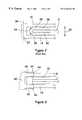
- FIG. 5is a perspective view of another embodiment of a disc travel limiter 40 made in accordance with the present invention.
- the example disc travel limiter 40 shown in the figureis suitable for use in a disc drive utilizing three discs.
- a person of skill in the artwill appreciate, however, that the disc travel limiter 40 can be readily modified for use with either a greater or lesser number of discs, and the scope of the invention should not, therefore, be considered as limited by the number of discs in the disc drive.
- the disc travel limiter 40can be seen to include four limiter arms 42 separated by three inter-arm spaces within which the discs (not shown) of the disc drive will be located.
- the limiter arms 42are connected by a backing member 50 which is also used to mount the entire disc travel limiter 40 to the disc drive housing.
- the specific method used to mount the disc travel limiter 40 within the disc drive housingis not considered as being limiting to the scope of the invention.
- the bottom surface of the backing member 50could include one or more tapped holes with the disc travel limiter 40 attached by a screw or screws, inserted through the bottom surface of the disc drive base member ( 4 in FIG. 1 ), or the disc travel limiter 40 could be adhesively attached to the base member. Other methods of attachment may suggest themselves to one of skill in the art without exceeding the envisioned scope of the invention.
- FIG. 5shows the limiter arms include cantilevered members 43 and contact features 44 which are generally semi-cylindrical in form. These semi-cylindrical contact surfaces 44 provide line-contact with the surfaces of the discs when an applied mechanical shock induces coning of sufficient magnitude, as previously described in relationship to FIG. 3 above.
- the present inventionenvisions that the disc travel limiter 40 will not only act as a limiter to contact the disc before it makes contact with the actuator head mounting arms ( 18 in FIGS. 1, 2 and 3 ), but also serve as a dampener to dissipate the energy caused by the application of mechanical shocks.
- the first design decision in implementing the present inventionis the selection of an appropriate low-modulus material, as noted above. Further control of the amount of dampening provided by the disc travel limiter 40 can be achieved by selection of the dimensions of certain elements of the disc travel limiter.
- Dimensions which can be selected to determine the dampening characteristicsinclude the length of the limiter arms 42 (i.e., the distance which the limiter arms 42 extend from the backing member 50 ), the width of the limiter arms 42 (i.e., the length of the linear contact surface), and, to the extent permitted by the interdisc spacing, the thickness of the limiter arms 42 .
- the selection of these dimensionswill, of course, be dependent upon such variables as the amount of applied mechanical shock which the disc drive is specified to withstand, the moving mass of the discs within the disc drive, the material characteristics of the disc travel limiter, all in accordance with well known behavioral characteristics of cantilevered beam elements.
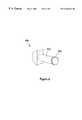
- FIG. 6shows an alternative configuration of the limiter arm 42 a of the disc travel limiter 40 a .
- a single limiter arm 42 acomprises a cantilevered member 43 a extending from a backing member 50 a , and can be seen to be generally cylindrical in form, as opposed to the substantially rectilinear form of the disc travel limiter 40 of FIG. 5 .
- the contact feature 44 a of this second embodiment of the inventionis generally circular, with a semi-cylindrical outer surface. This configuration provides a single-point contact with the disc, in contrast with the line-contact provided by the embodiment of FIG. 5 .
- control of the dampening characteristics of the disc travel limiter 40 acan be controlled by selection of the material and dimensions of the limiter arm 42 a.
Landscapes
- Moving Of Heads (AREA)
Abstract
Description
Claims (14)
Priority Applications (2)
| Application Number | Priority Date | Filing Date | Title |
|---|---|---|---|
| US09/133,274US6226144B1 (en) | 1997-08-15 | 1998-08-12 | Energy absorbing disc travel limiter |
| US09/753,827US6424487B2 (en) | 1997-08-15 | 2001-01-03 | Energy absorbing disc travel limiter with multiple adjacent cantilevered arms to limit disc deflection |
Applications Claiming Priority (2)
| Application Number | Priority Date | Filing Date | Title |
|---|---|---|---|
| US5590997P | 1997-08-15 | 1997-08-15 | |
| US09/133,274US6226144B1 (en) | 1997-08-15 | 1998-08-12 | Energy absorbing disc travel limiter |
Related Child Applications (1)
| Application Number | Title | Priority Date | Filing Date |
|---|---|---|---|
| US09/753,827ContinuationUS6424487B2 (en) | 1997-08-15 | 2001-01-03 | Energy absorbing disc travel limiter with multiple adjacent cantilevered arms to limit disc deflection |
Publications (1)
| Publication Number | Publication Date |
|---|---|
| US6226144B1true US6226144B1 (en) | 2001-05-01 |
Family
ID=26734750
Family Applications (2)
| Application Number | Title | Priority Date | Filing Date |
|---|---|---|---|
| US09/133,274Expired - LifetimeUS6226144B1 (en) | 1997-08-15 | 1998-08-12 | Energy absorbing disc travel limiter |
| US09/753,827Expired - Fee RelatedUS6424487B2 (en) | 1997-08-15 | 2001-01-03 | Energy absorbing disc travel limiter with multiple adjacent cantilevered arms to limit disc deflection |
Family Applications After (1)
| Application Number | Title | Priority Date | Filing Date |
|---|---|---|---|
| US09/753,827Expired - Fee RelatedUS6424487B2 (en) | 1997-08-15 | 2001-01-03 | Energy absorbing disc travel limiter with multiple adjacent cantilevered arms to limit disc deflection |
Country Status (1)
| Country | Link |
|---|---|
| US (2) | US6226144B1 (en) |
Cited By (13)
| Publication number | Priority date | Publication date | Assignee | Title |
|---|---|---|---|---|
| US6301073B1 (en)* | 1999-11-18 | 2001-10-09 | International Business Machines Corporation | Device for preventing mechanical shock-induced damage between actuator and disk in computer hard disk drive |
| US6504683B1 (en)* | 1999-11-01 | 2003-01-07 | Hitachi, Ltd. | Magnetic disk apparatus in which contact between a disk and a carriage arm by an external impact is prevented |
| US20050270691A1 (en)* | 2004-06-07 | 2005-12-08 | Pottebaum Kenneth L | Windage plate with snubber member to limit mechanical deflection |
| US20060002007A1 (en)* | 2004-07-03 | 2006-01-05 | Samsung Electronics Co., Ltd. | Hard disk drive having disk damper and disk protector |
| US20060176608A1 (en)* | 2005-02-04 | 2006-08-10 | Seagate Technology Llc | Disc storage system component with integrally formed snubbers |
| KR100833193B1 (en) | 2005-12-07 | 2008-05-28 | 삼성전자주식회사 | Apparatus for protecting disk and hard disk drive having the same |
| US20090055847A1 (en)* | 2005-01-19 | 2009-02-26 | Matsushita Electric Industrial Co., Ltd. | Disc device |
| US8289646B1 (en) | 2010-06-24 | 2012-10-16 | Western Digital Technologies, Inc. | Disk drive having a disk limiter that is disposed within an angular range relative to a base depression brim |
| US8446688B1 (en) | 2010-06-29 | 2013-05-21 | Western Digital Technologies, Inc. | Drive with circumferential disk limiter |
| US8553356B1 (en) | 2011-11-21 | 2013-10-08 | Western Digital Technologies, Inc. | Disk limiter for disk drive |
| US8743509B1 (en) | 2010-05-10 | 2014-06-03 | Western Digital Technologies, Inc. | Disk drive having a head loading ramp and a disk limiter tab that projects from a side of an actuator arm |
| US8797677B2 (en) | 2011-12-15 | 2014-08-05 | Western Digital Technologies, Inc. | Disk deflection damper for disk drive |
| US9520153B2 (en)* | 2015-04-03 | 2016-12-13 | Seagate Technology Llc | Apparatus with disc separator plates |
Families Citing this family (3)
| Publication number | Priority date | Publication date | Assignee | Title |
|---|---|---|---|---|
| US6624966B1 (en)* | 2001-05-31 | 2003-09-23 | Western Digital Technologies, Inc. | Disk drive having airflow suppressor comb for reduced disk rotation induced airflow |
| US6972926B1 (en) | 2002-01-31 | 2005-12-06 | Western Digital Technologies, Inc. | Disk drive having disk drive housing including airflow suppressor portion |
| US7006324B1 (en) | 2002-12-23 | 2006-02-28 | Western Digital Technologies, Inc. | Disk drive including an airflow blocker with a planar portion extending from a blocker arm portion |
Citations (7)
| Publication number | Priority date | Publication date | Assignee | Title |
|---|---|---|---|---|
| US4843503A (en)* | 1987-12-17 | 1989-06-27 | Priam Corporation | Head arm damping device for disc drive actuators |
| US5121278A (en) | 1985-12-18 | 1992-06-09 | Tdk Corporation | Disc cartridge having disc supporting arrangement |
| US5140478A (en) | 1989-11-22 | 1992-08-18 | Teac Corporation | Magnetic disk drive comprising magnetic disk cartridge and driving device which drives the disk cartridge and prevents external vibration from being transmitted to the disk cartridge |
| US5341260A (en) | 1992-12-04 | 1994-08-23 | Seagate Technology, Inc. | Reduced torque unloading ramp system for a hard disk drive |
| US5422770A (en)* | 1993-12-15 | 1995-06-06 | Integral Peripherals, Inc. | Shock bumper for a head/disk suspension |
| US5757587A (en) | 1994-10-17 | 1998-05-26 | International Business Machines Corporation | Direct access storage device having a disk motion limiter for preventing disk data zone and spindle bearing damage |
| US5801899A (en)* | 1995-10-06 | 1998-09-01 | Seagate Technology, Inc. | Mechanical shock protection for a disc drive |
Family Cites Families (1)
| Publication number | Priority date | Publication date | Assignee | Title |
|---|---|---|---|---|
| US6084744A (en)* | 1996-06-06 | 2000-07-04 | Seagate Technology, Inc. | Actuator assembly mounted disc snubber |
- 1998
- 1998-08-12USUS09/133,274patent/US6226144B1/ennot_activeExpired - Lifetime
- 2001
- 2001-01-03USUS09/753,827patent/US6424487B2/ennot_activeExpired - Fee Related
Patent Citations (7)
| Publication number | Priority date | Publication date | Assignee | Title |
|---|---|---|---|---|
| US5121278A (en) | 1985-12-18 | 1992-06-09 | Tdk Corporation | Disc cartridge having disc supporting arrangement |
| US4843503A (en)* | 1987-12-17 | 1989-06-27 | Priam Corporation | Head arm damping device for disc drive actuators |
| US5140478A (en) | 1989-11-22 | 1992-08-18 | Teac Corporation | Magnetic disk drive comprising magnetic disk cartridge and driving device which drives the disk cartridge and prevents external vibration from being transmitted to the disk cartridge |
| US5341260A (en) | 1992-12-04 | 1994-08-23 | Seagate Technology, Inc. | Reduced torque unloading ramp system for a hard disk drive |
| US5422770A (en)* | 1993-12-15 | 1995-06-06 | Integral Peripherals, Inc. | Shock bumper for a head/disk suspension |
| US5757587A (en) | 1994-10-17 | 1998-05-26 | International Business Machines Corporation | Direct access storage device having a disk motion limiter for preventing disk data zone and spindle bearing damage |
| US5801899A (en)* | 1995-10-06 | 1998-09-01 | Seagate Technology, Inc. | Mechanical shock protection for a disc drive |
Cited By (19)
| Publication number | Priority date | Publication date | Assignee | Title |
|---|---|---|---|---|
| US6504683B1 (en)* | 1999-11-01 | 2003-01-07 | Hitachi, Ltd. | Magnetic disk apparatus in which contact between a disk and a carriage arm by an external impact is prevented |
| US6301073B1 (en)* | 1999-11-18 | 2001-10-09 | International Business Machines Corporation | Device for preventing mechanical shock-induced damage between actuator and disk in computer hard disk drive |
| US20050270691A1 (en)* | 2004-06-07 | 2005-12-08 | Pottebaum Kenneth L | Windage plate with snubber member to limit mechanical deflection |
| US7310199B2 (en)* | 2004-06-07 | 2007-12-18 | Seagate Technology, Llc | Windage plate with snubber member to limit mechanical deflection |
| EP1615224A3 (en)* | 2004-07-03 | 2008-01-09 | Samsung Electronics Co., Ltd. | Hard disk drive having disk damper and disk protector |
| US20060002007A1 (en)* | 2004-07-03 | 2006-01-05 | Samsung Electronics Co., Ltd. | Hard disk drive having disk damper and disk protector |
| US7327530B2 (en) | 2004-07-03 | 2008-02-05 | Samsung Electronics Co., Ltd. | Hard disk drive having disk damper and disk protector |
| US7900219B2 (en) | 2005-01-19 | 2011-03-01 | Panasonic Corporation | Disc device having improved suppression of disc movement |
| US20090055847A1 (en)* | 2005-01-19 | 2009-02-26 | Matsushita Electric Industrial Co., Ltd. | Disc device |
| EP1855278A4 (en)* | 2005-01-19 | 2009-03-25 | Panasonic Corp | DISK DEVICE |
| US7307811B2 (en)* | 2005-02-04 | 2007-12-11 | Seagate Technology Llc | Disc storage system deck with integrally formed snubbers |
| US20060176608A1 (en)* | 2005-02-04 | 2006-08-10 | Seagate Technology Llc | Disc storage system component with integrally formed snubbers |
| KR100833193B1 (en) | 2005-12-07 | 2008-05-28 | 삼성전자주식회사 | Apparatus for protecting disk and hard disk drive having the same |
| US8743509B1 (en) | 2010-05-10 | 2014-06-03 | Western Digital Technologies, Inc. | Disk drive having a head loading ramp and a disk limiter tab that projects from a side of an actuator arm |
| US8289646B1 (en) | 2010-06-24 | 2012-10-16 | Western Digital Technologies, Inc. | Disk drive having a disk limiter that is disposed within an angular range relative to a base depression brim |
| US8446688B1 (en) | 2010-06-29 | 2013-05-21 | Western Digital Technologies, Inc. | Drive with circumferential disk limiter |
| US8553356B1 (en) | 2011-11-21 | 2013-10-08 | Western Digital Technologies, Inc. | Disk limiter for disk drive |
| US8797677B2 (en) | 2011-12-15 | 2014-08-05 | Western Digital Technologies, Inc. | Disk deflection damper for disk drive |
| US9520153B2 (en)* | 2015-04-03 | 2016-12-13 | Seagate Technology Llc | Apparatus with disc separator plates |
Also Published As
| Publication number | Publication date |
|---|---|
| US6424487B2 (en) | 2002-07-23 |
| US20010001254A1 (en) | 2001-05-17 |
Similar Documents
| Publication | Publication Date | Title |
|---|---|---|
| US6226144B1 (en) | Energy absorbing disc travel limiter | |
| US6961212B1 (en) | Shock isolation bearings and travel limit gaps in a spindle motor and disk drive using the same | |
| US5801899A (en) | Mechanical shock protection for a disc drive | |
| US6583963B2 (en) | Apparatus to improve shock capability of disc drives | |
| US6473270B1 (en) | Actuator shock snubber | |
| US6084744A (en) | Actuator assembly mounted disc snubber | |
| US6163441A (en) | Resonance dampening actuator bearing assembly | |
| US6487039B1 (en) | Disc-drive mounting method and apparatus to reduce noise | |
| US6236531B1 (en) | Flex support snubber | |
| US6542335B1 (en) | Inertial spring latch assembly and compressive limit stop in a disc drive | |
| CN1478270A (en) | Cartridge bearings with friction sleeves | |
| US6157520A (en) | Disc drive head suspension with gimbal contact feature for ramp load/unload | |
| US6125017A (en) | Actuator crash stops providing a two-stage braking impulse | |
| US6212029B1 (en) | Snubber for a disc drive | |
| US6714386B1 (en) | Disc drive having a suspension limiter for improved shock performance | |
| US5875073A (en) | Single, central limit stop for a disc drive actuator | |
| US6201666B1 (en) | Disc drive head suspension with single-point contact feature for ramp load/unload | |
| US6646826B1 (en) | Integrated cover and gasket assembly | |
| US6477000B1 (en) | Actuator arm disc snubber with unitary construction | |
| KR100445567B1 (en) | Inertia ring for improved rotational vibration performance | |
| US5835307A (en) | Magnetic disk unit having bent spring arm | |
| US6603634B1 (en) | Compressive spring sleeve for reducing disc slippage | |
| US6744606B2 (en) | Dual plane actuator | |
| US6417991B1 (en) | Recording disk drive | |
| US6744605B2 (en) | Low-profile pivot assembly |
Legal Events
| Date | Code | Title | Description |
|---|---|---|---|
| AS | Assignment | Owner name:SEAGATE TECHNOLOGY, INC., CALIFORNIA Free format text:ASSIGNMENT OF ASSIGNORS INTEREST;ASSIGNORS:NAGL, ALAN THOMAS;SOHM, HOWARD IRVING;REEL/FRAME:009602/0314 Effective date:19980902 | |
| AS | Assignment | Owner name:SEAGATE TECHNOLOGY LLC, CALIFORNIA Free format text:ASSIGNMENT OF ASSIGNORS INTEREST;ASSIGNOR:SEAGATE TECHNOLOGY, INC.;REEL/FRAME:010990/0383 Effective date:20000628 | |
| STCF | Information on status: patent grant | Free format text:PATENTED CASE | |
| AS | Assignment | Owner name:JPMORGAN CHASE BANK, AS COLLATERAL AGENT, NEW YORK Free format text:SECURITY AGREEMENT;ASSIGNOR:SEAGATE TECHNOLOGY LLC;REEL/FRAME:013177/0001 Effective date:20020513 Owner name:JPMORGAN CHASE BANK, AS COLLATERAL AGENT,NEW YORK Free format text:SECURITY AGREEMENT;ASSIGNOR:SEAGATE TECHNOLOGY LLC;REEL/FRAME:013177/0001 Effective date:20020513 | |
| FPAY | Fee payment | Year of fee payment:4 | |
| AS | Assignment | Owner name:SEAGATE TECHNOLOGY LLC, CALIFORNIA Free format text:RELEASE OF SECURITY INTERESTS IN PATENT RIGHTS;ASSIGNOR:JPMORGAN CHASE BANK, N.A. (FORMERLY KNOWN AS THE CHASE MANHATTAN BANK AND JPMORGAN CHASE BANK), AS ADMINISTRATIVE AGENT;REEL/FRAME:016945/0775 Effective date:20051130 | |
| FPAY | Fee payment | Year of fee payment:8 | |
| AS | Assignment | Owner name:WELLS FARGO BANK, NATIONAL ASSOCIATION, AS COLLATERAL AGENT AND SECOND PRIORITY REPRESENTATIVE, CALIFORNIA Free format text:SECURITY AGREEMENT;ASSIGNORS:MAXTOR CORPORATION;SEAGATE TECHNOLOGY LLC;SEAGATE TECHNOLOGY INTERNATIONAL;REEL/FRAME:022757/0017 Effective date:20090507 Owner name:JPMORGAN CHASE BANK, N.A., AS ADMINISTRATIVE AGENT AND FIRST PRIORITY REPRESENTATIVE, NEW YORK Free format text:SECURITY AGREEMENT;ASSIGNORS:MAXTOR CORPORATION;SEAGATE TECHNOLOGY LLC;SEAGATE TECHNOLOGY INTERNATIONAL;REEL/FRAME:022757/0017 Effective date:20090507 Owner name:JPMORGAN CHASE BANK, N.A., AS ADMINISTRATIVE AGENT Free format text:SECURITY AGREEMENT;ASSIGNORS:MAXTOR CORPORATION;SEAGATE TECHNOLOGY LLC;SEAGATE TECHNOLOGY INTERNATIONAL;REEL/FRAME:022757/0017 Effective date:20090507 Owner name:WELLS FARGO BANK, NATIONAL ASSOCIATION, AS COLLATE Free format text:SECURITY AGREEMENT;ASSIGNORS:MAXTOR CORPORATION;SEAGATE TECHNOLOGY LLC;SEAGATE TECHNOLOGY INTERNATIONAL;REEL/FRAME:022757/0017 Effective date:20090507 | |
| AS | Assignment | Owner name:SEAGATE TECHNOLOGY INTERNATIONAL, CALIFORNIA Free format text:RELEASE;ASSIGNOR:JPMORGAN CHASE BANK, N.A., AS ADMINISTRATIVE AGENT;REEL/FRAME:025662/0001 Effective date:20110114 Owner name:MAXTOR CORPORATION, CALIFORNIA Free format text:RELEASE;ASSIGNOR:JPMORGAN CHASE BANK, N.A., AS ADMINISTRATIVE AGENT;REEL/FRAME:025662/0001 Effective date:20110114 Owner name:SEAGATE TECHNOLOGY LLC, CALIFORNIA Free format text:RELEASE;ASSIGNOR:JPMORGAN CHASE BANK, N.A., AS ADMINISTRATIVE AGENT;REEL/FRAME:025662/0001 Effective date:20110114 Owner name:SEAGATE TECHNOLOGY HDD HOLDINGS, CALIFORNIA Free format text:RELEASE;ASSIGNOR:JPMORGAN CHASE BANK, N.A., AS ADMINISTRATIVE AGENT;REEL/FRAME:025662/0001 Effective date:20110114 | |
| AS | Assignment | Owner name:THE BANK OF NOVA SCOTIA, AS ADMINISTRATIVE AGENT, CANADA Free format text:SECURITY AGREEMENT;ASSIGNOR:SEAGATE TECHNOLOGY LLC;REEL/FRAME:026010/0350 Effective date:20110118 Owner name:THE BANK OF NOVA SCOTIA, AS ADMINISTRATIVE AGENT, Free format text:SECURITY AGREEMENT;ASSIGNOR:SEAGATE TECHNOLOGY LLC;REEL/FRAME:026010/0350 Effective date:20110118 | |
| FPAY | Fee payment | Year of fee payment:12 | |
| AS | Assignment | Owner name:SEAGATE TECHNOLOGY US HOLDINGS, INC., CALIFORNIA Free format text:TERMINATION AND RELEASE OF SECURITY INTEREST IN PATENT RIGHTS;ASSIGNOR:WELLS FARGO BANK, NATIONAL ASSOCIATION, AS COLLATERAL AGENT AND SECOND PRIORITY REPRESENTATIVE;REEL/FRAME:030833/0001 Effective date:20130312 Owner name:EVAULT INC. (F/K/A I365 INC.), CALIFORNIA Free format text:TERMINATION AND RELEASE OF SECURITY INTEREST IN PATENT RIGHTS;ASSIGNOR:WELLS FARGO BANK, NATIONAL ASSOCIATION, AS COLLATERAL AGENT AND SECOND PRIORITY REPRESENTATIVE;REEL/FRAME:030833/0001 Effective date:20130312 Owner name:SEAGATE TECHNOLOGY LLC, CALIFORNIA Free format text:TERMINATION AND RELEASE OF SECURITY INTEREST IN PATENT RIGHTS;ASSIGNOR:WELLS FARGO BANK, NATIONAL ASSOCIATION, AS COLLATERAL AGENT AND SECOND PRIORITY REPRESENTATIVE;REEL/FRAME:030833/0001 Effective date:20130312 Owner name:SEAGATE TECHNOLOGY INTERNATIONAL, CAYMAN ISLANDS Free format text:TERMINATION AND RELEASE OF SECURITY INTEREST IN PATENT RIGHTS;ASSIGNOR:WELLS FARGO BANK, NATIONAL ASSOCIATION, AS COLLATERAL AGENT AND SECOND PRIORITY REPRESENTATIVE;REEL/FRAME:030833/0001 Effective date:20130312 | |
| AS | Assignment | Owner name:SEAGATE TECHNOLOGY PUBLIC LIMITED COMPANY, CALIFORNIA Free format text:RELEASE BY SECURED PARTY;ASSIGNOR:THE BANK OF NOVA SCOTIA;REEL/FRAME:072193/0001 Effective date:20250303 Owner name:SEAGATE TECHNOLOGY, CALIFORNIA Free format text:RELEASE BY SECURED PARTY;ASSIGNOR:THE BANK OF NOVA SCOTIA;REEL/FRAME:072193/0001 Effective date:20250303 Owner name:SEAGATE TECHNOLOGY HDD HOLDINGS, CALIFORNIA Free format text:RELEASE BY SECURED PARTY;ASSIGNOR:THE BANK OF NOVA SCOTIA;REEL/FRAME:072193/0001 Effective date:20250303 Owner name:I365 INC., CALIFORNIA Free format text:RELEASE BY SECURED PARTY;ASSIGNOR:THE BANK OF NOVA SCOTIA;REEL/FRAME:072193/0001 Effective date:20250303 Owner name:SEAGATE TECHNOLOGY LLC, CALIFORNIA Free format text:RELEASE BY SECURED PARTY;ASSIGNOR:THE BANK OF NOVA SCOTIA;REEL/FRAME:072193/0001 Effective date:20250303 Owner name:SEAGATE TECHNOLOGY INTERNATIONAL, CAYMAN ISLANDS Free format text:RELEASE BY SECURED PARTY;ASSIGNOR:THE BANK OF NOVA SCOTIA;REEL/FRAME:072193/0001 Effective date:20250303 Owner name:SEAGATE HDD CAYMAN, CAYMAN ISLANDS Free format text:RELEASE BY SECURED PARTY;ASSIGNOR:THE BANK OF NOVA SCOTIA;REEL/FRAME:072193/0001 Effective date:20250303 Owner name:SEAGATE TECHNOLOGY (US) HOLDINGS, INC., CALIFORNIA Free format text:RELEASE BY SECURED PARTY;ASSIGNOR:THE BANK OF NOVA SCOTIA;REEL/FRAME:072193/0001 Effective date:20250303 |