US6226035B1 - Adjustable imaging system with wide angle capability - Google Patents
Adjustable imaging system with wide angle capabilityDownload PDFInfo
- Publication number
- US6226035B1 US6226035B1US09/034,208US3420898AUS6226035B1US 6226035 B1US6226035 B1US 6226035B1US 3420898 AUS3420898 AUS 3420898AUS 6226035 B1US6226035 B1US 6226035B1
- Authority
- US
- United States
- Prior art keywords
- optical system
- wide
- view
- image
- interest
- Prior art date
- Legal status (The legal status is an assumption and is not a legal conclusion. Google has not performed a legal analysis and makes no representation as to the accuracy of the status listed.)
- Expired - Lifetime
Links
Images


Classifications
- G—PHYSICS
- G02—OPTICS
- G02B—OPTICAL ELEMENTS, SYSTEMS OR APPARATUS
- G02B13/00—Optical objectives specially designed for the purposes specified below
- G02B13/06—Panoramic objectives; So-called "sky lenses" including panoramic objectives having reflecting surfaces
- G—PHYSICS
- G02—OPTICS
- G02B—OPTICAL ELEMENTS, SYSTEMS OR APPARATUS
- G02B17/00—Systems with reflecting surfaces, with or without refracting elements
- G02B17/02—Catoptric systems, e.g. image erecting and reversing system
- G02B17/06—Catoptric systems, e.g. image erecting and reversing system using mirrors only, i.e. having only one curved mirror
- G—PHYSICS
- G03—PHOTOGRAPHY; CINEMATOGRAPHY; ANALOGOUS TECHNIQUES USING WAVES OTHER THAN OPTICAL WAVES; ELECTROGRAPHY; HOLOGRAPHY
- G03B—APPARATUS OR ARRANGEMENTS FOR TAKING PHOTOGRAPHS OR FOR PROJECTING OR VIEWING THEM; APPARATUS OR ARRANGEMENTS EMPLOYING ANALOGOUS TECHNIQUES USING WAVES OTHER THAN OPTICAL WAVES; ACCESSORIES THEREFOR
- G03B15/00—Special procedures for taking photographs; Apparatus therefor
- G03B15/08—Trick photography
- G03B15/12—Trick photography using mirrors
- G—PHYSICS
- G03—PHOTOGRAPHY; CINEMATOGRAPHY; ANALOGOUS TECHNIQUES USING WAVES OTHER THAN OPTICAL WAVES; ELECTROGRAPHY; HOLOGRAPHY
- G03B—APPARATUS OR ARRANGEMENTS FOR TAKING PHOTOGRAPHS OR FOR PROJECTING OR VIEWING THEM; APPARATUS OR ARRANGEMENTS EMPLOYING ANALOGOUS TECHNIQUES USING WAVES OTHER THAN OPTICAL WAVES; ACCESSORIES THEREFOR
- G03B17/00—Details of cameras or camera bodies; Accessories therefor
- G03B17/02—Bodies
- G03B17/17—Bodies with reflectors arranged in beam forming the photographic image, e.g. for reducing dimensions of camera
- G—PHYSICS
- G03—PHOTOGRAPHY; CINEMATOGRAPHY; ANALOGOUS TECHNIQUES USING WAVES OTHER THAN OPTICAL WAVES; ELECTROGRAPHY; HOLOGRAPHY
- G03B—APPARATUS OR ARRANGEMENTS FOR TAKING PHOTOGRAPHS OR FOR PROJECTING OR VIEWING THEM; APPARATUS OR ARRANGEMENTS EMPLOYING ANALOGOUS TECHNIQUES USING WAVES OTHER THAN OPTICAL WAVES; ACCESSORIES THEREFOR
- G03B37/00—Panoramic or wide-screen photography; Photographing extended surfaces, e.g. for surveying; Photographing internal surfaces, e.g. of pipe
- G—PHYSICS
- G08—SIGNALLING
- G08B—SIGNALLING OR CALLING SYSTEMS; ORDER TELEGRAPHS; ALARM SYSTEMS
- G08B13/00—Burglar, theft or intruder alarms
- G08B13/18—Actuation by interference with heat, light, or radiation of shorter wavelength; Actuation by intruding sources of heat, light, or radiation of shorter wavelength
- G08B13/189—Actuation by interference with heat, light, or radiation of shorter wavelength; Actuation by intruding sources of heat, light, or radiation of shorter wavelength using passive radiation detection systems
- G08B13/194—Actuation by interference with heat, light, or radiation of shorter wavelength; Actuation by intruding sources of heat, light, or radiation of shorter wavelength using passive radiation detection systems using image scanning and comparing systems
- G08B13/196—Actuation by interference with heat, light, or radiation of shorter wavelength; Actuation by intruding sources of heat, light, or radiation of shorter wavelength using passive radiation detection systems using image scanning and comparing systems using television cameras
- G08B13/19617—Surveillance camera constructional details
- G08B13/19626—Surveillance camera constructional details optical details, e.g. lenses, mirrors or multiple lenses
- H—ELECTRICITY
- H04—ELECTRIC COMMUNICATION TECHNIQUE
- H04N—PICTORIAL COMMUNICATION, e.g. TELEVISION
- H04N23/00—Cameras or camera modules comprising electronic image sensors; Control thereof
- H04N23/60—Control of cameras or camera modules
- H04N23/698—Control of cameras or camera modules for achieving an enlarged field of view, e.g. panoramic image capture
Definitions
- This inventiongenerally relates to optics and cameras.
- the inventionrelates more specifically to optical systems for obtaining both wide and narrow fields of view of an area of interest.
- PTZpan-tilt-zoom
- a PTZ camerais mounted in a transparent dome above or on the ceiling of the area of interest.
- the camerausually is a closed-circuit television camera.
- the camerais controlled remotely or automatically in order to view regions of interest within the room.
- While such camerascan view any region, area of interest, or target, they have a relatively narrow field of view, and cannot see all regions at once.
- the camerais commanded to pan, tilt, and/or zoom as necessary to bring the new region of interest into view.
- the process of panning, tilting, and/or zooming to the new region of interest or targettakes time, and when the camera is viewing the new region or target, it can no longer see the original region. This limits the effectiveness of such cameras, since activities can only be monitored, recorded or tracked in one area at a time. Unmonitored areas are subject to unmonitored intrusions.
- Omnidirectional imaging systemshave been developed which permit simultaneous viewing and image capture of an entire room. These systems employ an image sensor that is mounted to receive light rays reflected from a wide-angle reflector, such as a parabolic mirror, in order to capture an omnidirectional, often hemispherical image. Embodiments of omnidirectional imaging systems are described in U.S. patent application Ser. No. 08/644,903, entitled “Omnidirectional Imaging Apparatus,” filed May 10, 1996.
- omnidirectional imaging systemsprovide only a wide-angle view of the area of interest. Because of the large viewing angle used to provide the wide-angle view, the resulting image has limited resolution. For example, when a video camera is used to capture a video image of a large room using a wide-angle view, a relatively small number of pixels of the video display are used to display each region of the room. Consequently, it is hard to make out details of the area of interest or to locate small objects. Further, the camera is fixed with respect to the wide angle optical system. As a result, a video image generated from the image sensor's signal shows the room or area of interest only from the viewpoint of the wide-angle reflector, and the views of the room have relatively low resolution.
- Omnidirectional camerasalso have been developed using fisheye lenses to capture wide, panoramic images.
- the resolution of the images produced by all the above-described systemsis limited by the fact that the field of view is projected onto a sensor which is typically used to generate an image for a much narrower field of view.
- a conventional sensormight produce an image on a computer display screen having 640 ⁇ 480 pixels. Similar levels of resolution are supported by broadcast standards such as NTSC and S-video. Sensors with higher resolution are unusual and are very expensive; one reason is that it is difficult to capture and transmit the large amount of image data involved in real time.
- the number of pixels of the sensor that is available for any particular region in the imageis relatively small, especially for omnidirectional systems with very wide fields of view.
- an optical systemthat can provide both a wide-angle view of an area of interest and a narrower view of a particular region within the area of interest, using a single image sensor, while maintaining registration between the wide field of view and close-up view when the image sensor is moved from the wide-angle view to a narrower view.
- an optical systemthat fulfills the foregoing needs and can be remotely controlled to carry out movement from the wide-angle view to the narrower view.
- an optical systemthat provides a wide field of view and a direct field of view of an area of interest, comprising a wide-angle optical system that reflects electromagnetic radiation from the wide field of view in the area of interest; an image sensor that can sense the radiation and generate a signal representing a visible image from the radiation; and means for moving the image sensor to a first position in which the image sensor receives the radiation reflected from the wide-angle optical system and forms a wide field of view image of the area of interest, and for moving the image sensor to a second position away from the wide-angle optical system in which the image sensor receives radiation from the area of interest and forms a direct field of view image.
- the image sensorreceives radiation from the area of interest without the radiation being first reflected from the wide-angle optical system and forms a direct field of view image. Another feature is means for redirecting radiation reflected from the wide-angle optical system to the image sensor. Still another feature is that the wide-angle optical system provides a substantially hemispherical field of view of the area of interest.
- the wide-angle optical systemcomprises a curved mirror.
- the curved mirroris formed with a partial quadric surface.
- the curved mirroris a spherical mirror.
- the curved mirroris a parabolic mirror.
- the curved mirroris a hyperbolic mirror.
- the curved mirroris an elliptical mirror.
- the wide-angle optical systemcomprises a plurality of planar mirrors.
- the wide-angle optical systemcomprises a faceted surface, and in which each facet of the faceted surface is a mirror. Still another feature is that the wide-angle optical system comprises a faceted surface, and in which each facet of the faceted surface is a curved mirror.
- the wide-angle optical systemcomprises a curved mirror and a second mirror aligned to receive radiation reflected from the curved mirror and to direct the reflected radiation to the image sensor.
- the wide-angle optical systemcomprises a curved mirror, and in which the means for redirecting radiation comprises a planar mirror aligned to receive radiation reflected from the curved mirror and to direct the reflected radiation to the image sensor. Still another feature is that the means for redirecting radiation comprises one or more reflecting surfaces. A related feature is that the means for redirecting radiation comprises one or more refracting surfaces. Another related feature is that the means for redirecting radiation comprises one or more optical fibers.
- the image sensor and the means for moving the image sensorcomprises a pan-tilt-zoom (PTZ) camera.
- the means for redirecting radiation received from the wide-angle optical system to the image sensorcomprises a relay lens axially aligned with a zoom lens.
- the image sensor and the means for moving the image sensorcomprises a pan-tilt-zoom (PTZ) camera.
- the image sensoris aligned, when in the first position, to receive the radiation along an imaging axis that is substantially coincident with an optical axis of the wide-angle optical system.
- the optical systemfurther comprises one or more processors; and a memory coupled to the one or more processors, the memory having stored therein sequences of instructions which, when executed by the one or more processors, cause the one or more processors to move the image sensor from the first position to the second position by causing the processor to perform the steps of determining first coordinates of a first viewpoint associated with the wide field of view image, second coordinates of a second viewpoint associated with the direct field of view image, and direction of a target in a first coordinate system associated with the first viewpoint; converting the direction into a ray extending from the first viewpoint to the target; computing an intersection of the ray with values describing a reference plane on which the target lies to obtain third coordinates; translating the third coordinates into a second coordinate system that is associated with the second viewpoint to obtain fourth coordinates; and converting the fourth coordinates into a pan angle value, a tilt angle value, and a focal distance value representing the second position.
- sequences of instructionsfurther cause the one or more processors to carry out the step of commanding the image sensor to move from the first position to the second position according to the pan angle value, tilt angle value, and focal distance value.
- the optical systemfurther comprises one or more processors; and a memory coupled to the one or more processors, the memory having stored therein a plurality of presets, each of the presets comprising information describing a pre-defined position of the image sensor that provides a direct view of the area of interest; and sequences of instructions which, when executed by the one or more processors, cause the one or more processors to move the image sensor from the first position to the second position by causing the processor to perform the steps of determining first coordinates of a first viewpoint associated with the wide field of view image, second coordinates of a second viewpoint associated with the direct field of view image, and direction of a target in a first coordinate system associated with the first viewpoint; converting the direction into a ray extending from the first viewpoint to the target; computing an intersection of the ray with values describing a reference plane on which the target lies to obtain third coordinates; translating the third coordinates into fourth coordinates in a second coordinate system that is associated with the second viewpoint; and selecting one of the plurality of preset
- sequences of instructionsfurther comprise instructions that cause the processor to carry out the step of commanding the image sensor to move to the selected preset.
- the plurality of presetscollectively defines direct views of the entire area of interest.
- each of the presetscomprises values representing a pan position, tilt position, and zoom position of the image sensor.
- the optical systemfurther comprises a computer-readable medium carrying sequences of instructions which, when executed by one or more processors, cause the one or more processors to move the image sensor from the first position to the second position by causing the processor to perform the steps of determining first coordinates of a first viewpoint associated with the wide field of view image, second coordinates of a second viewpoint associated with the direct field of view image, and direction of a target in a first coordinate system associated with the first viewpoint; converting the third coordinates into a ray extending from the first viewpoint to the target; computing an intersection of the ray with values describing a reference plane on which the target lies to obtain third coordinates; translating the third coordinates into a second coordinate system that is associated with the second viewpoint to obtain fourth coordinates; and converting the fourth coordinates into a pan angle value, a tilt angle value, and a focal distance value representing angular and focal differences of the first position from the second position.
- sequences of instructionsfurther cause the one or more processors to carry out the step of commanding the image sensor to move from the first position to the second position according to the pan angle value, tilt angle value, and focal distance value.
- the optical systemfurther comprises a computer-readable medium having stored therein a plurality of presets, each of the presets comprising information describing a pre-defined position of the image sensor that provides a direct view of the area of interest; and sequences of instructions which, when executed by one or more processors, cause the one or more processors to move the image sensor from the first position to the second position by causing the processor to perform the steps of determining first coordinates of a first viewpoint associated with the wide field of view image, second coordinates of a second viewpoint associated with the direct field of view image, and direction of a target in a first coordinate system associated with the first viewpoint to obtain third coordinates; converting the third coordinates into a ray extending from the first viewpoint to the target; computing an intersection of the ray with values describing a reference plane on which the target lies; translating the third coordinates into fourth coordinates in a second coordinate system that is associated with the second viewpoint; and selecting one of the plurality of presets that provides a direct view of a region of the
- sequences of instructionsfurther comprise instructions that cause the processor to carry out the step of commanding the image sensor to move to the selected preset.
- the plurality of presetscollectively defines direct views of the entire area of interest.
- each of the presetscomprises values representing a pan position, tilt position, and zoom position of the image sensor.
- the image sensoris mounted to point toward the wide-angle optical system, and to receive light rays reflected from it. In this orientation, the image sensor produces, with an appropriate zoom setting, a wide-angle image.
- the image sensorproduces a conventional narrow field image with greater resolution when the image sensor is oriented at a region of interest and away from the wide-angle optical system. Registration is achieved and maintained between the wide field of view and narrow field of view images.
- FIG. 1is a simplified side elevation view of a first embodiment of an optical system.
- FIG. 2Ais a simplified side elevation view of a second embodiment of an optical system.
- FIG. 2Bis a simplified side elevation view of a third embodiment of an optical system.
- FIG. 3Ais a simplified side elevation view of a fourth embodiment of an optical system.
- FIG. 3Bis a simplified profile diagram of the geometry of a parabolic mirror that is truncated off-axis.
- FIG. 4Ais a diagram of geometric relationships among elements of the optical systems of FIG. 1 .
- FIG. 4Bis a flow diagram of a first embodiment of a method of moving an image sensor from a first position to a second position.
- FIG. 5Ais perspective view of geometric relationships among elements of the optical systems of FIG. 1, FIG. 2, and FIG. 3 A.
- FIG. 5Bis a flow diagram of a second embodiment of a method of moving an image sensor from a first position to a second position.
- FIG. 6is a diagram of a computer system that can be used to carry out certain computations related to the embodiments of FIG. 4 B and FIG. 5 B.
- FIG. 1is a side elevation view of a first embodiment of an optical system 2 within a room or area of interest 4 for which surveillance or viewing is desired.
- An image sensor 20is mounted on the ceiling 18 of the area of interest 4 , using an appropriate mounting bracket having a ceiling fixture 22 and a downwardly vertically extending arm 24 .
- the image sensor 20is a video camera that can pan or tilt toward the area of interest 4 , so as to view any region of interest within the area of interest, and optically zoom-in to capture a detailed view of a narrower region.
- the image sensor 20has a zoom lens 26 that can move under electronic control.
- the image sensor 20also has motors and controls that enable the image sensor to move laterally (pan) and move up and down (tilt), under electronic control The pan and tilt motors may be used to point the image sensor 20 in an arbitrary direction.
- the specific configuration, size, and type of the fixture 22 and arm 24are not critical, as long as the image sensor 20 is separated from the ceiling 18 by a vertical distance sufficient to allow the image sensor to be aligned with the optical elements of the system 2 , which will be described below.
- Pan-tilt-zoom camerasthat can be used as the image sensor 20 are commercially available from Philips N.V., Sensormatic, Pelco, Kalatel, and other manufacturers.
- An example of a mounting structure that can be used for the image sensor 20is described in U.S. Pat. No. 5,627,616 (Sergeant et al.), incorporated herein by reference.
- the image sensor 20is a device that can receive electromagnetic radiation reflected as described below and that can form an image or other tangible representation of the radiation.
- the image sensor 20is a video camera having a zoom lens 26 .
- the image sensor 20is a still camera that uses conventional photographic film, motion picture photographic camera, digital still frame camera, camcorder, or digital video camera.
- a wide-angle optical system 10is mounted to the ceiling 18 of the area of interest 4 .
- the wide-angle optical system 10is mounted in alignment with the image sensor 20 along axis 32 , and in reasonable proximity to the image sensor.
- the particular distance separating the image sensor 20 from the wide-angle optical system 10is not critical. The distance is dependent on several factors, such as the amount of ambient light in the area of interest 4 , the aperture, type and focal length of the lens of the image sensor 20 , and other factors.
- the wide-angle optical system 10comprises a mirror 12 mounted to the ceiling 18 .
- the mirror 12is a convex mirror formed such that the curved outer surface of the mirror 12 is directed downward into the area of interest 4 .
- the mirror 12is formed as a paraboloid.
- the mirror 12is formed of a polymer or plastic coated with a reflective material, glass, polished steel, or any other suitable reflecting material.
- the mirror 12is defined in cylindrical coordinates, r, ⁇ and z, as generally conforming to the equation
- zis the axis of rotation
- ris the radial coordinate
- his a constant substantially representing twice the focal length of the mirror 12 .
- the z axisis coincident with the optical axis of the wide-angle imaging system.
- a focus point 52 of the paraboloid defined by the above equationis coincident with the origin of the coordinate system.
- the mirror 12is truncated along a plane 13 that is parallel to the ceiling 18 and which includes the focus point 52 . In other embodiments, the paraboloid is extended past the plane containing its focus.
- a planar mirror 14is mounted at a 45-degree angle with respect to the horizontal plane of the ceiling 18 .
- the image sensor 20When the image sensor 20 is pointing at the planar mirror, light rays reflected vertically downward from the parabolic mirror 12 are directed horizontally along axis 32 to the lens of the image sensor 20 .
- a relay lens 16is mounted in a location horizontally disposed between the zoom lens 26 of the image sensor 20 and the planar mirror 14 .
- the relay lenscan be formed in any manner that is suitable to cause principal rays of electromagnetic radiation reflected from the mirror 12 to become aligned substantially parallel to the central axis 32 of the zoom lens.
- the relay lensmay be located between the parabolic mirror and the planar mirror.
- all incoming light rays 90 that are reflected from the area of interest 4are reflected by the mirror 12 in a substantially vertical direction to the planar mirror 14 .
- the planar mirror 14redirects the optical path of the light rays 90 along a generally horizontal axis 32 , through the relay lens 16 and the zoom lens 26 and into the image sensor 20 .
- All incoming light rays 90 that would otherwise pass through the focus point 52are orthographically reflected towards the planar mirror 14 by the paraboloid mirror 12 .
- the focus point 52is coincident with the single viewpoint from which the image formed at the image sensor 20 is viewed.
- planar mirror 14positioned at a 45-degree angle with respect to the optical axis 15 of the paraboloid mirror 12 , such that the center of the planar mirror is generally aligned with the optical axis 15 . Accordingly, an image of a substantially hemispherical scene is formed orthographically at the image sensor 20 . In alternative embodiments, extending or shortening the mirror provide more or less than a hemispherical view, respectively.
- the image sensor 20generates an electronic signal such as an NTSC video signal that is representative of the reflected image, which is coupled by a signal transmission means 102 , such as a cable, to a framegrabber 104 .
- the framegrabber 104is a conventional video signal frame grabber, such as a Matrox Meteor card.
- the framegrabber 104converts the video signal into a framebuffer which is updated at 30 Hz and provides it to a general-purpose computer 106 having an output display 108 .
- the computer 106is programmed to enable a user to view any desired portion of the image received by the image sensor 20 , and to control the image sensor to zoom in on a selected portion of the scene, or to tilt or pan the scene in any desired manner.
- a usercan command the image sensor 20 to directly view any region of interest within the area of interest 4 , without receiving an image reflected from the mirror 12 .
- the cameraIn embodiments in which the image sensor 20 is a conventional PTZ camera, as is known in this art, the camera generally has three stepper motors and a movable platform or mount.
- One of the stepper motorsis coupled to the zoom lens 26 of the camera, so that rotation of the motor causes the zoom lens to move to a different focal length.
- a gear on a shaft of the motorcooperates with a toothed ring affixed to the outside surface of the zoom lens, so that when the motor shaft turns, the gear urges the ring to rotate the zoom lens.
- Second and third motorscontrol movable surfaces that pan and tilt the camera. Additional motors may be used for auxiliary functions such as iris control.
- a PTZ Controller 110is coupled to the computer 106 , for example, through an RS-232 serial data link. Alternatively, an RS-485 serial data link is used.
- the PTZ Controller 110receives commands from the computer over the RS-232 link, transforms the commands into one or more controlled voltage signals, and communicates the signals to the motors.
- Position or velocity sensorssuch as potentiometers are coupled to the motors to enable the PTZ Controller 110 to receive feedback about the movement and position of the motors.
- An example of a computer-controlled pan-tilt unit suitable for use with an image sensor in the embodiments described hereinis Model PTU-46-17.5, available from Directed Perception, Inc.
- An exemplary PTZ camerais described in U.S. Pat. No. 5,627,616 (Sergeant et al.).
- the optical system 2also includes a mechanism, in the program that controls the computer 106 , for persistently storing values that identify the pan, tilt, and zoom position of the image sensor 20 when the camera is directed at the wide angle optical system 10 rather than at the area of interest 4 .
- a mechanismin the program that controls the computer 106 , for persistently storing values that identify the pan, tilt, and zoom position of the image sensor 20 when the camera is directed at the wide angle optical system 10 rather than at the area of interest 4 .
- these valuesenables the operator of the image sensor 20 to rapidly move the camera from a view of the area of interest 4 to view images reflected front the wide-angle optical system 10 .
- the valuesmay be stored in the PTZ controller 110 .
- the planar mirror 14serves as a light redirection means. Any other light redirection means may be substituted, including one or more reflecting surfaces, one or more refracting surfaces and/or one or more optical fibers or optical fiber bundles. Alternatively, the planar mirror 14 may be made non-planar, for purposes of enhancing the image.
- the convex parabolic mirror 12is merely an example of a means for achieving the wide-angle optical system 10 .
- the wide-angle optical system 10uses a concave parabolic mirror, a hyperbolic mirror, elliptical mirror, or spherical mirror, and modified lenses that achieve an orthographic projection of the target or region of interest.
- planar mirrorsFor example, four planar triangular mirrors are arranged to form a convex pyramidal reflecting surface to achieve a wide field of view.
- An assembly of the four planar triangular mirrorsis mounted in the embodiment of FIG. 1 in place of the mirror 12 , such that the apex of the pyramidal reflecting surface is directed vertically downward and the base of the pyramidal reflecting surface is mounted to the ceiling 18 .
- An assembly of this type used for omnidirectional imagingis described in U.S. Pat. No. 5,539,483 (Nalwa), incorporated herein by reference. Nalwa uses this optical configuration with four separate image sensors to obtain a single viewpoint.
- four rigidly coupled camerasare used, or a single camera is used.
- An omnidirectional imaging systemcan be constructed using a camera, a parabolic mirror and a telecentric lens.
- the telecentric lensmay be effectively approximated using a conventional zoom lens and a relay lens.
- a telecentric lensis sometimes not required when the wide-angle optical system uses a mirror formed in a shape other than paraboloid.
- a wide-angle optical systemcan comprise a hyperbolic mirror and a conventional perspective lens.
- the zoom lens of a PTZ cameraserves as the perspective lens; alternatively, a relay lens is used.
- the use of a telecentric lens, relay lens, or other means for rendering reflected radiation telecentricis not necessarily required.
- FIG. 2Ais a diagram of an alternate embodiment of an optical system 2 that comprises a wide-angle optical system 10 and an image sensor 20 .
- a mirror 12is preferably mounted on the inside top surface or ceiling 18 of the area of interest 4 .
- the image sensor 20is mounted using a bracket or mount 28 so that the image sensor is positioned vertically below and orthogonal to the ceiling 18 and the relay lens 16 .
- the zoom lens 26 of the image sensor 20is mounted to face substantially vertically upwardly and is aligned with an optical axis 15 of the wide-angle optical system 10 .
- the mirror 12preferably is a convex parabolic or paraboloid mirror.
- incoming light rays 90 from the area of interest 4are reflected from the mirror 12 vertically downward through the relay lens 16 .
- the light rays 90are directed through the relay lens 16 toward the zoom lens 26 .
- the relay lens 16 and the zoom lens 26cause the rays 90 reflected along the axis 15 of the mirror 12 to be telecentric.
- the embodiment of FIG. 2Aavoids certain optical losses and additional maintenance that might be entailed with the embodiment of FIG. 1 .
- An advantage of the embodiment of FIG. 2Ais that the wide-angle optical system and the image sensor can be incorporated into one unit such that the wide-angle optical system and the image sensor have a rigid, fixed geometric relationship. Consequently, it is unnecessary to calibrate the relative positions of the wide-angle optical system and the image sensor when the unit is installed.
- the mount 28is constructed of a transparent material or using thin materials so as to minimize the obstruction of rays 90 by the mount 28 .
- FIG. 2Bis a diagram of another embodiment in which first and second cameras 20 a , 20 b are mounted in vertically opposite positions to view first and second parabolic mirrors 12 a , 12 b respectively.
- the horizontal or bottom surfaces 18 a , 18 b of the parabolic mirrors 12 a , 12 bare mounted in close proximity. Alternatively, they are secured together.
- Each image sensor 20 a , 20 bviews light reflected from one of the parabolic mirrors 12 a , 12 b through first and second lenses 16 a , 16 b .
- the lenses 16 a , 16 b and the mirrors 12 a , 12 bform a wide-angle optical system.
- the back-to-back configuration of the mirrors 12 a , 12 benables the cameras 20 a , 20 b to collectively view the entire area of interest 4 with a spherical field of view.
- each of the mirrors 12 a , 12 bis mounted in a protective transparent hemispherical dome that is made, for example, of high-impact clear plastic.
- the lens 16 ais mounted in a tube, one end of which is secured to the dome that is opposite mirror 12 a .
- the zoom lens of the image sensor 20 ais secured to the other end of the tube. In this configuration, the mirrors, lenses, and cameras are rigidly mounted together, facilitating use of the unit in a secured area.
- FIG. 3Ashows another embodiment of an optical system 2 , comprising a wide-angle optical system 10 and an image sensor 20 .
- the image sensor 20is affixed to the top surface 18 or ceiling of the area of interest 4 by a mount 28 .
- the lower end 29 of the mount 28is affixed to the image sensor 20 at an angle such that the image sensor is directed angularly upward at the wide-angle optical system 10 .
- a mirror 12preferably a truncated convex parabolic mirror, is mounted to the top surface 18 using an appropriate mount 34 .
- the flat upper non-reflecting base 13 of the mirror 12is secured to the mount 34 at an acute angle with respect to the horizontal plane of the floor or ceiling of the area of interest 4 .
- the mirror 12is secured to the mount 34 using a plate or fixture that can be tilted and rotated with respect to the end of the mount 34 , enabling the mirror to be aligned with axis 15 .
- the optical sensor 20is attached to its mount 28 using a fixture that can be tilted and rotated with respect to the mount 28 , facilitating alignment of the image sensor with an optical axis of the mirror.
- the optical axis 15 of the convex parabolic mirror 12is aligned with the center axis of a zoom lens 26 of the image sensor 20 .
- a relay lens 16is mounted normal to the optical axis at a position between the zoom lens 26 and the mirror 12 using a suitable mount. In the preferred embodiment, the relay lens 16 is mounted in a fixed relationship to the mirror 12 .
- incoming light rays 90are uniformly reflected in alignment with the optical axis 15 of the mirror 12 .
- the angular mounting of the mirrorcauses the optical axis 15 to be aligned at an angle with respect to the horizontal.
- the reflected light rays 90are directed through the relay lens 16 to the zoom lens 26 .
- the relay lens 16 and the zoom lens 26operate to cause the reflected light rays 90 to be telecentric when the light rays 90 arrive at the image sensor 20 .
- FIG. 3Bis a diagram of the geometry of a parabolic object 300 that is cut off-axis.
- the optical axis 302 of the parabolic object 300is normal to the base 306 .
- parabolic object 300is formed with an off-axis base 304 arranged at an angle with respect to the optical axis 302 .
- the parabolic mirror 300is mounted on a substantially vertical mount, and the optical axis 302 is directed at an angle to an image sensor.
- the mirror 12is cut off-axis, substantially hemispherical views are achieved at the image sensor 20 even though the image sensor is mounted at an angle with respect to the base 13 of the mirror.
- the mirroris mounted on a movable fixture.
- the movable fixtureenables the mirror to be laterally panned and vertically tilted, so that the axis of the mirror 12 is easily aligned with that of the image sensor 20 .
- FIG. 3Aeliminates the need for the light redirection means shown in FIG. 1 . It also avoids potential mechanical and optical interference in the path of the light rays 90 that could be caused by the mount 28 shown in the embodiment of FIG. 2 A.
- the image sensor 20provides an analog video signal to an interface in the computer system.
- the interfacedigitizes the analog video signal and directs digital data representing the video signal to a frame buffer or other memory system.
- the memory systemis a two-port memory that can simultaneously and in real time receive digital image data and output the digital data to a display, such as a computer monitor.
- the interface and the memory systemoperate under control of conventional driver software. In this configuration, the image processing system continually acquires image information from the image sensor 20 and displays it on the computer display.
- the image processing systemalso includes an application program that allows a human end user to manipulate the image displayed on the computer display, and carry out other image processing functions.
- the application programmay also carry out camera control functions such as remote control of pan, tilt, and zoom functions of the camera. Using these functions, the image sensor can be moved to directly view the room or area of interest without the aid of the wide-angle reflector.
- the image sensor's signalshows the area of interest from the separate viewpoint of the image sensor. Accordingly, it is difficult for an operator of the image sensor to smoothly and accurately move the image sensor to directly view an object of interest that is shown in wide-angle image. Instead, the operator must move the image sensor from a wide-angle view to a direct view, adjust to the location of objects in the area of interest, and then apply appropriate pan, tilt, or zoom commands to guide the image sensor to the correct position.
- an operatoridentifies a target in the area of interest 4 while viewing the area of interest using an image reflected from the wide-angle optical system 10 to the image sensor 20 . It can be difficult to select the appropriate pan angle, tilt angle, and zoom distance for the camera that will cause a direct image from the camera to show the target, because of the difference in image appearance and perspective in the direct view compared to the wide angle view. It is also time-consuming and error-prone to search the area of interest 4 using the direct image, because it has a narrow field of view.
- each of the foregoing embodimentspreferably includes a mechanism for registering the wide field of view images that are produced by the wide-angle optical system 10 with those produced by the image sensor 20 .
- the registration mechanismis important, for example, in order to permit a user to control the pan, tilt and zoom of an image sensor 20 by selecting a point or region of interest within the area of interest 4 as depicted in the wide field of view image.
- a registration mechanismis also needed to enable the pan, tilt and zoom of an image sensor 20 to be controlled smoothly when the camera is being used to track a moving object that is shown in an omnidirectional image reflected from the wide angle optical system 10 .
- FIG. 4Ais a diagram of the embodiment of FIG. 1, additionally showing a target 50 within the area of interest 4 .
- the image sensor 20is positioned to directly view the target 50 without the aid of the wide-angle optical system 10 .
- the target 50can be viewed from two distinct viewpoints.
- a first viewpoint 52is that of the wide-angle optical system 10 , coincident with the focal point of the mirror 12 .
- a second viewpoint 54is that of the image sensor 20 .
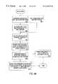
- the registration mechanismis implemented in one or more computer programs or programmatic objects, executed by the computer system 106 , that carry out steps of a process shown in the flow diagram of FIG. 4 B.
- step 402in an initialization or calibration process, the relative positions of the viewpoints 52 , 54 are specified or may be determined. For example, the relative positions of the viewpoints may be directly measured and recorded at the time the equipment is installed.
- step 404the direction of the target 50 with respect to viewpoint 52 is determined or specified.
- steps 402 and 404may involve various user input steps and coordinate transformation steps. For example, assume that the display 108 is showing an image from the image sensor 20 and reflected from the wide-angle optical system 10 . The user identifies the target 50 on the display 108 .
- the usermoves a cursor generated by the computer system over the target 50 , and presses a button on the pointing device.
- an application program running in the computer system 106records values of two-dimensional Cartesian coordinates that represent the position of the cursor at the time the button was pressed. The coordinates represent a point within the target 50 . Accounting for the size of the target 50 will be described below.
- the direction of the target with respect to viewpoint 52may be unambiguously converted to a ray 62 from the viewpoint 52 to the target 50 , as shown in step 406 .
- the distance of the target 50 from the viewpoint 52is still ambiguous.
- the target 50could be anywhere along the ray. Therefore, information about the ray 62 is insufficient to supply values needed to control the image sensor 20 to produce a direct image of the target 50 .
- One method of determining the needed valuesis to assume that the target 50 lies on the plane of the floor 6 of the area of interest 4 .
- the distance of the wide view optical system 10 to the floor 6is established, as shown in step 408 .
- the ray from viewpoint 52 to the target 50is intersected with the plane of the floor 6 to obtain the point at which the target 50 is located, as shown in step 410 .
- Values for the angular or relative pan and tilt positions of the image sensor 20are determined by translating the position of the target 50 into coordinates within a reference frame originating at the camera viewpoint 54 , as shown in step 412 . Converting the Cartesian coordinates into spherical coordinates yields values for the pan and tilt angles and the focal distance of the image sensor 20 , as shown in step 414 .
- the image sensoris commanded to move to the position indicated by the values of the pan angle, tilt angle, and focal distance. In this way, an operator can smoothly select an object from the wide-angle display and cause the image sensor to rapidly locate the object in a direct view.
- the plane of the floor 6is used in this example, but in fact any plane may be used, as long as it does not contain the viewpoint 52 .
- the usercan indicate the size of the target 50 by specifying more than one point for the location of the target 50 . For example, the user clicks on multiple points located around the perimeter of the object. Each such point is used to generate a set of spherical coordinates about the camera viewpoint 54 , using the same process described above.
- the zoom lens 26 of the image sensor 20is set to contain an angle subtended by the coordinates.
- a motion detectoris coupled to the computer system 106 .
- the computer systemreceives input from the motion detector when the motion detector detects motion of a target.
- the computer systemconverts the location of the target in the motion detector's field of detection into a set of target coordinates in one of the coordinate systems.
- other means for sensing a target areaare provided, for example, a proximity sensor, an infrared sensor, a detector based on radar, and a visible light detector.
- FIG. 5Ais a perspective view of the embodiment of FIG. 4A, showing angular relationships and coordinate relationships in additional detail.
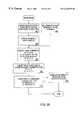
- FIG. 5Bis a flow diagram showing an alternate method of registration. The method of FIG. 5B involves a transformation from a coordinate system CS 2 of the wide-angle optical system 10 , having its origin at the viewpoint 52 , to a coordinate system CS 1 or the image sensor 20 , having its origin at the viewpoint 54 .
- the target 50is assumed to lie in a known horizontal plane, so that its height with respect to the two coordinate systems CS 1 , CS 2 is z 1 , z 2 , respectively.
- the position of the viewpoint 52is known to be vector S.
- the target height values and the values of vector Sare received.
- the valuesare set as constants in a computer program running on the computer system 106 that implements the method of FIG. 5 B.
- the valuesare entered and saved in a persistent data storage device when the system is installed.
- the pan angle ⁇ 2 and the tilt angle ⁇ 2are obtained, as shown in step 504 , when the user selects a target in the image.
- the values ⁇ 2 and ⁇ 2are the pan angle and tilt angle, respectively, for the target 50 with respect to the wide angle optical system.
- the pan angle ⁇ 2 and tilt angle ⁇ 2define the direction of a vector from the focus of the paraboloid mirror 12 to the chosen point on the target.
- the pan angle ⁇ 2 and tilt angle ⁇ 2are obtained by mapping x and y coordinates of the point in the image to spherical coordinates about the viewpoint 52 . For the case of a parabolic mirror, this may be achieved using the following mapping:
- the height of the target in CS 2is known. We let the height of the floor with respect to CS 2 by Z 2 ; it is typically negative in value.
- Z 2the height of the floor with respect to CS 2 ; it is typically negative in value.
- Y 2the following procedure is used. As shown in step 506 , spherical to Cartesian coordinate conversions are carried out:
- the location of the targetthen can be expressed in CS 2 coordinates:
- T 2(x 2 , y 2 , z 2 )
- T 1(x 1 , y 1 , z 1 )
- r 1⁇ square root over (x 1 2 +L +y 1 2 +L +z 1 2 +L ) ⁇
- ⁇ 1tan ⁇ 1 (y 1 /x 1 )
- ⁇ 1cos ⁇ 1 (z 1 /r 1 )
- These valuesare the zoom, pan and tilt values for the adjustable image sensor, respectively.
- An alternative strategy for obtaining the direct viewuses control systems integral to typical commercially available PTZ camera systems.
- Some PTZ camera systems that are commercially availablenow can store one or more preset camera positions, commonly called “presets”. Each preset has a unique identifier, such as a number.
- Each presetis a persistently stored set of values that represent a camera position, such as a pan value, tilt value, and zoom value.
- a presetis stored by commanding the camera to move to a particular position, and then issuing a “preset save” command or the equivalent.
- the camera systemIn response to the preset save command, the camera system records, in persistent data storage, values reflecting the then-current pan position, tilt position, and zoom position. At some later time, the user may command the system to move to a particular preset. In response, the camera system computes the amount of movement needed to move from its current pan, tilt, and zoom positions to new positions that correspond to the preset values. The camera system then executes a move to those positions.
- a set of presetsare created that define camera positions which, taken together, entirely cover the area of interest.
- the camerais then moved, using another preset, to a position directed at the wide-angle optical system, so that a wide-angle view is obtained.
- the camerais commanded to move to one of the preset narrower views by selecting the preset having position values which result in the best view of the target.
- each of the presetsis established using a relatively wide zoom setting of the zoom lens.
- the set of presetsis created in such a way that their union covers the entire wide field of view. After the target is captured in the narrower view using one of the presets, the user may manually zoom in, if desired.
- substantially more elaborate schemes for eliminating ambiguity in the distance of targetsmay be envisioned. These include, for example, tables of distances of fixed objects in the field of view, and hints based on knowledge of objects, occlusion and relative size. For example, if an object is recognized as a person, and persons are known in general to measure about six feet tall, and the object's size in the image is visible, then the distance of the person from a viewpoint of the image can be inferred using appropriate mathematics and geometry.
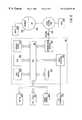
- FIG. 6is a block diagram that illustrates a computer system 106 upon which an embodiment of the invention may be implemented.
- Computer system 106includes a bus 602 or other communication mechanism for communicating information, and a processor 604 coupled with bus 602 for processing information.
- Computer system 106also includes a main memory 606 , such as a random access memory (RAM) or other dynamic storage device, coupled to bus 602 for storing information and instructions to be executed by processor 604 .
- Main memory 606also may be used for storing temporary variables or other intermediate information during execution of instructions to be executed by processor 604 .
- Computer system 106further includes a read only memory (ROM) 608 or other static storage device coupled to bus 602 for storing static information and instructions for processor 604 .
- ROMread only memory
- a storage device 610such as a magnetic disk or optical disk, is provided and coupled to bus 602 for storing information and instructions.
- Computer system 106may be coupled via bus 602 to a display 612 , such as a cathode ray tube (CRT), for displaying information to a computer user.
- a display 612such as a cathode ray tube (CRT)
- An input device 614is coupled to bus 602 for communicating information and command selections to processor 604 .
- cursor control 616is Another type of user input device
- cursor control 616such as a mouse, a trackball, or cursor direction keys for communicating direction information and command selections to processor 604 and for controlling cursor movement on display 612 .
- This input devicetypically has two degrees of freedom in two axes, a first axis (e.g., x) and a second axis (e.g., y), that allows the device to specify positions in a plane.
- the inventionis related to the use of computer system 106 for registering an image from one coordinate system to another.
- registering an image from one coordinate system to anotheris provided by computer system 106 in response to processor 604 executing one or more sequences of one or more instructions contained in main memory 606 .
- Such instructionsmay be read into main memory 606 from another computer-readable medium, such as storage device 610 .
- Execution of the sequences of instructions contained in main memory 606causes processor 604 to perform the process steps described herein.
- hard-wired circuitrymay be used in place of or in combination with software instructions to implement the invention.
- embodiments of the inventionare not limited to any specific combination of hardware circuitry and software.
- Non-volatile mediaincludes, for example, optical or magnetic disks, such as storage device 610 .
- Volatile mediaincludes dynamic memory, such as main memory 606 .
- Transmission mediaincludes coaxial cables, copper wire and fiber optics, including the wires that comprise bus 602 . Transmission media can also take the form of acoustic or light waves, such as those generated during radio-wave and infra-red data communications.
- Computer-readable mediainclude, for example, a floppy disk, a flexible disk, hard disk, magnetic tape, or any other magnetic medium, a CD-ROM, any other optical medium, punch cards, paper tape, any other physical medium with patterns of holes, a RAM, a PROM, and EPROM, a FLASH-EPROM, any other memory chip or cartridge, a carrier wave as described hereinafter, or any other medium from which a computer can read.
- Various forms of computer readable mediamay be involved in carrying one or more sequences of one or more instructions to processor 604 for execution.
- the instructionsmay initially be carried on a magnetic disk of a remote computer.
- the remote computercan load the instructions into its dynamic memory and send the instructions over a telephone line using a modem.
- a modem local to computer system 106can receive the data on the telephone line and use an infrared transmitter to convert the data to an infrared signal.
- An infrared detectorcan receive the data carried in the infrared signal and appropriate circuitry can place the data on bus 602 .
- Bus 602carries the data to main memory 606 , from which processor 604 retrieves and executes the instructions.
- the instructions received by main memory 606may optionally be stored on storage device 610 either before or after execution by processor 604 .
- Computer system 106also includes a communication interface 618 coupled to bus 602 .
- Communication interface 618provides a two-way data communication coupling to a network link 620 that is connected to a local network 622 .
- communication interface 618may be an integrated services digital network (ISDN) card or a modem to provide a data communication connection to a corresponding type of telephone line.
- ISDNintegrated services digital network
- communication interface 618may be a local area network (LAN) card to provide a data communication connection to a compatible LAN.
- LANlocal area network
- Wireless linksmay also be implemented.
- communication interface 618sends and receives electrical, electromagnetic or optical signals that carry digital data streams representing various types of information.
- Network link 620typically provides data communication through one or more networks to other data devices.
- network link 620may provide a connection through local network 622 to a host computer 624 or to data equipment operated by an Internet Service Provider (ISP) 626 .
- ISP 626in turn provides data communication services through the world-wide packet data communication network now commonly referred to as the “Internet” 628 .
- Internet 628uses electrical, electromagnetic or optical signals that carry digital data streams.
- the signals through the various networks and the signals on network link 620 and through communication interface 618which carry the digital data to and from computer system 106 , are exemplary forms of carrier waves transporting the information.
- Computer system 106can send messages and receive data, including program code, through the network(s), network link 620 and communication interface 618 .
- a server 630might transmit a requested code for an application program through Internet 628 , ISP 626 , local network 622 and communication interface 618 .
- one such downloaded applicationprovides for registering an image from one coordinate system to another as described herein.
- the received codemay be executed by processor 604 as it is received, and/or stored in storage device 610 , or other non-volatile storage for later execution. In this manner, computer system 106 may obtain application code in the form of a carrier wave.
- the computer system 106also has an RS232 serial link 632 or interface coupled to the bus 602 .
- the RS232 serial link 632provides an input/output interface for data communicated using the IEEE RS232 protocol to the PTZ Controller 110 .
- the RS232 serial linkcan be read or written by the processor 604 to communicate data from a storage device or main memory to the PTZ Controller 110 .
Landscapes
- Physics & Mathematics (AREA)
- General Physics & Mathematics (AREA)
- Optics & Photonics (AREA)
- Engineering & Computer Science (AREA)
- Multimedia (AREA)
- Signal Processing (AREA)
- Studio Devices (AREA)
Abstract
Description
Claims (52)
Priority Applications (3)
| Application Number | Priority Date | Filing Date | Title |
|---|---|---|---|
| US09/034,208US6226035B1 (en) | 1998-03-04 | 1998-03-04 | Adjustable imaging system with wide angle capability |
| PCT/US1999/004589WO1999045422A1 (en) | 1998-03-04 | 1999-03-03 | Adjustable imaging system with wide angle capability |
| AU30662/99AAU3066299A (en) | 1998-03-04 | 1999-03-03 | Adjustable imaging system with wide angle capability |
Applications Claiming Priority (1)
| Application Number | Priority Date | Filing Date | Title |
|---|---|---|---|
| US09/034,208US6226035B1 (en) | 1998-03-04 | 1998-03-04 | Adjustable imaging system with wide angle capability |
Publications (1)
| Publication Number | Publication Date |
|---|---|
| US6226035B1true US6226035B1 (en) | 2001-05-01 |
Family
ID=21874971
Family Applications (1)
| Application Number | Title | Priority Date | Filing Date |
|---|---|---|---|
| US09/034,208Expired - LifetimeUS6226035B1 (en) | 1998-03-04 | 1998-03-04 | Adjustable imaging system with wide angle capability |
Country Status (3)
| Country | Link |
|---|---|
| US (1) | US6226035B1 (en) |
| AU (1) | AU3066299A (en) |
| WO (1) | WO1999045422A1 (en) |
Cited By (151)
| Publication number | Priority date | Publication date | Assignee | Title |
|---|---|---|---|---|
| US20010015751A1 (en)* | 1998-06-16 | 2001-08-23 | Genex Technologies, Inc. | Method and apparatus for omnidirectional imaging |
| US20020024599A1 (en)* | 2000-08-17 | 2002-02-28 | Yoshio Fukuhara | Moving object tracking apparatus |
| US6392821B1 (en)* | 2000-09-28 | 2002-05-21 | William R. Benner, Jr. | Light display projector with wide angle capability and associated method |
| US6424377B1 (en)* | 1996-06-24 | 2002-07-23 | Be Here Corporation | Panoramic camera |
| US6493032B1 (en)* | 1996-06-24 | 2002-12-10 | Be Here Corporation | Imaging arrangement which allows for capturing an image of a view at different resolutions |
| US20020196330A1 (en)* | 1999-05-12 | 2002-12-26 | Imove Inc. | Security camera system for tracking moving objects in both forward and reverse directions |
| US6545702B1 (en)* | 1998-09-08 | 2003-04-08 | Sri International | Method and apparatus for panoramic imaging |
| US20030071891A1 (en)* | 2001-08-09 | 2003-04-17 | Geng Z. Jason | Method and apparatus for an omni-directional video surveillance system |
| US20030095338A1 (en)* | 2001-10-29 | 2003-05-22 | Sanjiv Singh | System and method for panoramic imaging |
| US20030098909A1 (en)* | 2001-11-29 | 2003-05-29 | Martin Fritzsche | Process for monitoring the internal space of a vehicle, as well as a vehicle with at least one camera within the vehicle cabin |
| US20030105565A1 (en)* | 2001-12-03 | 2003-06-05 | Loda David C. | Integrated internet portal and deployed product microserver management system |
| FR2835925A1 (en)* | 2002-02-11 | 2003-08-15 | Egg Solution Optronics | Correction device for panoramic image acquisition system comprises set of lenses so that rays coming from reflector and/or refractive device diverge towards whole of camera image capture element |
| US6611282B1 (en)* | 1999-01-04 | 2003-08-26 | Remote Reality | Super wide-angle panoramic imaging apparatus |
| US20030180039A1 (en)* | 2002-02-21 | 2003-09-25 | Noritoshi Kakou | Camera device and monitoring system |
| US6654019B2 (en) | 1998-05-13 | 2003-11-25 | Imove, Inc. | Panoramic movie which utilizes a series of captured panoramic images to display movement as observed by a viewer looking in a selected direction |
| US6717610B1 (en)* | 1998-11-25 | 2004-04-06 | Donnelly Corporation | Wide angle image capture system for vehicle |
| US6738073B2 (en)* | 1999-05-12 | 2004-05-18 | Imove, Inc. | Camera system with both a wide angle view and a high resolution view |
| US20040141060A1 (en)* | 2003-01-20 | 2004-07-22 | Masatoshi Tsuji | Surveillance camera system |
| US20040189801A1 (en)* | 2003-03-28 | 2004-09-30 | Chao-Hung Chang | Active video surveillance system and active video surveillance method therefore |
| US20040201698A1 (en)* | 2001-06-08 | 2004-10-14 | Keenan Vaughn E. | Camera-based system for capturing images of a target area |
| US20040254424A1 (en)* | 2003-04-15 | 2004-12-16 | Interscience, Inc. | Integrated panoramic and forward view endoscope |
| US20040263646A1 (en)* | 2003-06-24 | 2004-12-30 | Microsoft Corporation | Whiteboard view camera |
| US20050007478A1 (en)* | 2003-05-02 | 2005-01-13 | Yavuz Ahiska | Multiple-view processing in wide-angle video camera |
| US20050088741A1 (en)* | 2003-10-24 | 2005-04-28 | Brian Purser | Security viewing apparatus and method |
| US20050099509A1 (en)* | 2003-11-10 | 2005-05-12 | Fuji Photo Film Co., Ltd. | Image taking apparatus |
| US20050104958A1 (en)* | 2003-11-13 | 2005-05-19 | Geoffrey Egnal | Active camera video-based surveillance systems and methods |
| US20050111084A1 (en)* | 2003-11-24 | 2005-05-26 | Mandella Michael J. | Solid catadioptric lens with a single viewpoint |
| US6924832B1 (en)* | 1998-08-07 | 2005-08-02 | Be Here Corporation | Method, apparatus & computer program product for tracking objects in a warped video image |
| US20050253951A1 (en)* | 2002-09-09 | 2005-11-17 | Rohm Co., Ltd. | Image sensor module |
| US20050259084A1 (en)* | 2004-05-21 | 2005-11-24 | Popovich David G | Tiled touch system |
| US20060028547A1 (en)* | 2004-08-04 | 2006-02-09 | Chao-Hung Chang | Integrated active surveillance system |
| GB2417570A (en)* | 2004-08-25 | 2006-03-01 | Simon Richard Daniel | Deployable cylindrical panoramic projection apparatus |
| US20060072757A1 (en)* | 2004-09-24 | 2006-04-06 | Martin Renkis | Wireless video surveillance system and method with emergency video access |
| US20060095539A1 (en)* | 2004-10-29 | 2006-05-04 | Martin Renkis | Wireless video surveillance system and method for mesh networking |
| US7050085B1 (en) | 2000-10-26 | 2006-05-23 | Imove, Inc. | System and method for camera calibration |
| US20060132907A1 (en)* | 2003-11-24 | 2006-06-22 | Electronic Scripting Products, Inc. | Solid catadioptric lens with two viewpoints |
| US7071964B1 (en)* | 2004-08-23 | 2006-07-04 | Otto Gregory Glatt | 360-degree panoramic scene-storage device |
| WO2005013001A3 (en)* | 2003-07-03 | 2006-07-13 | Physical Optics Corp | Panoramic video system with real-time distortion-free imaging |
| US7161624B1 (en)* | 1999-04-16 | 2007-01-09 | Fujinon Corporation | Remote control pan head system |
| US20070024738A1 (en)* | 2005-07-29 | 2007-02-01 | Kunihiko Kanai | Image capturing apparatus |
| US7176960B1 (en)* | 1999-09-20 | 2007-02-13 | The Trustees Of Columbia University In The City Of New York | System and methods for generating spherical mosaic images |
| US20070058717A1 (en)* | 2005-09-09 | 2007-03-15 | Objectvideo, Inc. | Enhanced processing for scanning video |
| US7215359B2 (en) | 2004-09-03 | 2007-05-08 | International Business Machines Corporation | Techniques for view control of imaging units |
| US20070165007A1 (en)* | 2006-01-13 | 2007-07-19 | Gerald Morrison | Interactive input system |
| US20070182817A1 (en)* | 2006-02-07 | 2007-08-09 | Donnelly Corporation | Camera mounted at rear of vehicle |
| US20070205994A1 (en)* | 2006-03-02 | 2007-09-06 | Taco Van Ieperen | Touch system and method for interacting with the same |
| US7310440B1 (en)* | 2001-07-13 | 2007-12-18 | Bae Systems Information And Electronic Systems Integration Inc. | Replacement sensor model for optimal image exploitation |
| US20080002962A1 (en)* | 2006-06-30 | 2008-01-03 | Opt Corporation | Photographic device |
| US20080068352A1 (en)* | 2004-02-17 | 2008-03-20 | Smart Technologies Inc. | Apparatus for detecting a pointer within a region of interest |
| DE102006042022A1 (en)* | 2006-09-07 | 2008-03-27 | Christian Sebler | All-round view camera for use in instrument panel of vehicle for monitoring environment, has convex or conical mirror, where mirror and camera are arranged in common housing and form compact component |
| US20080111881A1 (en)* | 2006-11-09 | 2008-05-15 | Innovative Signal Analysis, Inc. | Imaging system |
| US20080117296A1 (en)* | 2003-02-21 | 2008-05-22 | Objectvideo, Inc. | Master-slave automated video-based surveillance system |
| US7379119B1 (en) | 2003-10-15 | 2008-05-27 | Replex Mirror Company | Surveillance camera mount |
| US20080122922A1 (en)* | 2006-11-23 | 2008-05-29 | Geng Z Jason | Wide field-of-view reflector and method of designing and making same |
| US20080129700A1 (en)* | 2006-12-04 | 2008-06-05 | Smart Technologies Inc. | Interactive input system and method |
| US20080143821A1 (en)* | 2006-12-16 | 2008-06-19 | Hung Yi-Ping | Image Processing System For Integrating Multi-Resolution Images |
| US20080231867A1 (en)* | 2007-03-23 | 2008-09-25 | Kye Systems Corp. | Mechanism for positioning device |
| US20080232790A1 (en)* | 2007-03-23 | 2008-09-25 | David Lai | Camera monitor |
| US20080303901A1 (en)* | 2007-06-08 | 2008-12-11 | Variyath Girish S | Tracking an object |
| US20090102937A1 (en)* | 2005-11-21 | 2009-04-23 | Mehmed Yilmaz | Long-distance image capture device |
| US20090160801A1 (en)* | 2003-03-11 | 2009-06-25 | Smart Technologies Ulc | System and method for differentiating between pointers used to contact touch surface |
| US20090207234A1 (en)* | 2008-02-14 | 2009-08-20 | Wen-Hsiung Chen | Telepresence system for 360 degree video conferencing |
| US20090244257A1 (en)* | 2008-03-26 | 2009-10-01 | Macdonald Alan J | Virtual round-table videoconference |
| US7619617B2 (en) | 2002-11-15 | 2009-11-17 | Smart Technologies Ulc | Size/scale and orientation determination of a pointer in a camera-based touch system |
| US7643006B2 (en) | 2003-09-16 | 2010-01-05 | Smart Technologies Ulc | Gesture recognition method and touch system incorporating the same |
| US20100110005A1 (en)* | 2008-11-05 | 2010-05-06 | Smart Technologies Ulc | Interactive input system with multi-angle reflector |
| US20100207911A1 (en)* | 2003-02-14 | 2010-08-19 | Next Holdings Limited | Touch screen Signal Processing With Single-Point Calibration |
| US20100220188A1 (en)* | 2004-09-30 | 2010-09-02 | Renkis Martin A | Wireless Video Surveillance System and Method with Input Capture and Data Transmission Prioritization and Adjustment |
| US20100225588A1 (en)* | 2009-01-21 | 2010-09-09 | Next Holdings Limited | Methods And Systems For Optical Detection Of Gestures |
| US20100321473A1 (en)* | 2007-10-04 | 2010-12-23 | Samsung Techwin Co., Ltd. | Surveillance camera system |
| USD636359S1 (en) | 2010-03-21 | 2011-04-19 | Cisco Technology, Inc. | Video unit with integrated features |
| USD636747S1 (en) | 2010-03-21 | 2011-04-26 | Cisco Technology, Inc. | Video unit with integrated features |
| US20110095977A1 (en)* | 2009-10-23 | 2011-04-28 | Smart Technologies Ulc | Interactive input system incorporating multi-angle reflecting structure |
| USD637570S1 (en) | 2010-03-21 | 2011-05-10 | Cisco Technology, Inc. | Mounted video unit |
| USD637568S1 (en) | 2010-03-21 | 2011-05-10 | Cisco Technology, Inc. | Free-standing video unit |
| USRE42794E1 (en) | 1999-12-27 | 2011-10-04 | Smart Technologies Ulc | Information-inputting device inputting contact point of object on recording surfaces as information |
| US8055022B2 (en) | 2000-07-05 | 2011-11-08 | Smart Technologies Ulc | Passive touch system and method of detecting user input |
| US8089462B2 (en) | 2004-01-02 | 2012-01-03 | Smart Technologies Ulc | Pointer tracking across multiple overlapping coordinate input sub-regions defining a generally contiguous input region |
| US20120002048A1 (en)* | 2008-12-23 | 2012-01-05 | Mobotix Ag | Omnibus camera |
| US8094137B2 (en) | 2007-07-23 | 2012-01-10 | Smart Technologies Ulc | System and method of detecting contact on a display |
| USRE43084E1 (en) | 1999-10-29 | 2012-01-10 | Smart Technologies Ulc | Method and apparatus for inputting information including coordinate data |
| US8115753B2 (en) | 2007-04-11 | 2012-02-14 | Next Holdings Limited | Touch screen system with hover and click input methods |
| US8149221B2 (en) | 2004-05-07 | 2012-04-03 | Next Holdings Limited | Touch panel display system with illumination and detection provided from a single edge |
| US20120206566A1 (en)* | 2010-10-11 | 2012-08-16 | Teachscape, Inc. | Methods and systems for relating to the capture of multimedia content of observed persons performing a task for evaluation |
| US8274496B2 (en) | 2004-04-29 | 2012-09-25 | Smart Technologies Ulc | Dual mode touch systems |
| US20120242782A1 (en)* | 2011-03-24 | 2012-09-27 | Hon Hai Precision Industry Co., Ltd. | Image capture device and image processing method |
| US8289299B2 (en) | 2003-02-14 | 2012-10-16 | Next Holdings Limited | Touch screen signal processing |
| US8384693B2 (en) | 2007-08-30 | 2013-02-26 | Next Holdings Limited | Low profile touch panel systems |
| US8390667B2 (en) | 2008-04-15 | 2013-03-05 | Cisco Technology, Inc. | Pop-up PIP for people not in picture |
| USD678308S1 (en) | 2010-12-16 | 2013-03-19 | Cisco Technology, Inc. | Display screen with graphical user interface |
| USD678320S1 (en) | 2010-12-16 | 2013-03-19 | Cisco Technology, Inc. | Display screen with graphical user interface |
| USD678307S1 (en) | 2010-12-16 | 2013-03-19 | Cisco Technology, Inc. | Display screen with graphical user interface |
| US8405636B2 (en) | 2008-01-07 | 2013-03-26 | Next Holdings Limited | Optical position sensing system and optical position sensor assembly |
| USD678894S1 (en) | 2010-12-16 | 2013-03-26 | Cisco Technology, Inc. | Display screen with graphical user interface |
| US8432377B2 (en) | 2007-08-30 | 2013-04-30 | Next Holdings Limited | Optical touchscreen with improved illumination |
| USD682293S1 (en) | 2010-12-16 | 2013-05-14 | Cisco Technology, Inc. | Display screen with graphical user interface |
| USD682294S1 (en) | 2010-12-16 | 2013-05-14 | Cisco Technology, Inc. | Display screen with graphical user interface |
| USD682864S1 (en) | 2010-12-16 | 2013-05-21 | Cisco Technology, Inc. | Display screen with graphical user interface |
| USD682854S1 (en) | 2010-12-16 | 2013-05-21 | Cisco Technology, Inc. | Display screen for graphical user interface |
| US8456447B2 (en) | 2003-02-14 | 2013-06-04 | Next Holdings Limited | Touch screen signal processing |
| US8456418B2 (en) | 2003-10-09 | 2013-06-04 | Smart Technologies Ulc | Apparatus for determining the location of a pointer within a region of interest |
| US20130155225A1 (en)* | 2011-12-19 | 2013-06-20 | Kabushiki Kaisha Topcon | Surveying Apparatus |
| US20130155224A1 (en)* | 2011-12-19 | 2013-06-20 | Kabushiki Kaisha Topcon | Rotation Angle Detecting Apparatus And Surveying Instrument |
| US8472415B2 (en) | 2006-03-06 | 2013-06-25 | Cisco Technology, Inc. | Performance optimization with integrated mobility and MPLS |
| US8477175B2 (en) | 2009-03-09 | 2013-07-02 | Cisco Technology, Inc. | System and method for providing three dimensional imaging in a network environment |
| WO2013101049A1 (en)* | 2011-12-29 | 2013-07-04 | Intel Corporation | Systems, methods, and apparatus for enhancing a camera field of view in a vehicle |
| US8542264B2 (en) | 2010-11-18 | 2013-09-24 | Cisco Technology, Inc. | System and method for managing optics in a video environment |
| US8599934B2 (en) | 2010-09-08 | 2013-12-03 | Cisco Technology, Inc. | System and method for skip coding during video conferencing in a network environment |
| US8599865B2 (en) | 2010-10-26 | 2013-12-03 | Cisco Technology, Inc. | System and method for provisioning flows in a mobile network environment |
| US20140015920A1 (en)* | 2012-07-13 | 2014-01-16 | Vivotek Inc. | Virtual perspective image synthesizing system and its synthesizing method |
| US8659639B2 (en) | 2009-05-29 | 2014-02-25 | Cisco Technology, Inc. | System and method for extending communications between participants in a conferencing environment |
| US8659637B2 (en) | 2009-03-09 | 2014-02-25 | Cisco Technology, Inc. | System and method for providing three dimensional video conferencing in a network environment |
| US8670019B2 (en) | 2011-04-28 | 2014-03-11 | Cisco Technology, Inc. | System and method for providing enhanced eye gaze in a video conferencing environment |
| US8682087B2 (en) | 2011-12-19 | 2014-03-25 | Cisco Technology, Inc. | System and method for depth-guided image filtering in a video conference environment |
| US8692768B2 (en) | 2009-07-10 | 2014-04-08 | Smart Technologies Ulc | Interactive input system |
| US8692862B2 (en) | 2011-02-28 | 2014-04-08 | Cisco Technology, Inc. | System and method for selection of video data in a video conference environment |
| US8694658B2 (en) | 2008-09-19 | 2014-04-08 | Cisco Technology, Inc. | System and method for enabling communication sessions in a network environment |
| US8699457B2 (en) | 2010-11-03 | 2014-04-15 | Cisco Technology, Inc. | System and method for managing flows in a mobile network environment |
| US8723914B2 (en) | 2010-11-19 | 2014-05-13 | Cisco Technology, Inc. | System and method for providing enhanced video processing in a network environment |
| US8730297B2 (en) | 2010-11-15 | 2014-05-20 | Cisco Technology, Inc. | System and method for providing camera functions in a video environment |
| US8750513B2 (en) | 2004-09-23 | 2014-06-10 | Smartvue Corporation | Video surveillance system and method for self-configuring network |
| US8786631B1 (en) | 2011-04-30 | 2014-07-22 | Cisco Technology, Inc. | System and method for transferring transparency information in a video environment |
| US8797377B2 (en) | 2008-02-14 | 2014-08-05 | Cisco Technology, Inc. | Method and system for videoconference configuration |
| US8842179B2 (en) | 2004-09-24 | 2014-09-23 | Smartvue Corporation | Video surveillance sharing system and method |
| US8896655B2 (en) | 2010-08-31 | 2014-11-25 | Cisco Technology, Inc. | System and method for providing depth adaptive video conferencing |
| US8902193B2 (en) | 2008-05-09 | 2014-12-02 | Smart Technologies Ulc | Interactive input system and bezel therefor |
| US8902244B2 (en) | 2010-11-15 | 2014-12-02 | Cisco Technology, Inc. | System and method for providing enhanced graphics in a video environment |
| US20140368607A1 (en)* | 2007-09-21 | 2014-12-18 | The Trustees Of Columbia University In The City Of New York | Systems And Methods For Panoramic Imaging |
| US8934026B2 (en) | 2011-05-12 | 2015-01-13 | Cisco Technology, Inc. | System and method for video coding in a dynamic environment |
| US8947493B2 (en) | 2011-11-16 | 2015-02-03 | Cisco Technology, Inc. | System and method for alerting a participant in a video conference |
| US8977987B1 (en) | 2010-06-14 | 2015-03-10 | Google Inc. | Motion-based interface control on computing device |
| US20150085083A1 (en)* | 2013-09-25 | 2015-03-26 | National Central University | Image-capturing system with dual lens camera |
| US9082297B2 (en) | 2009-08-11 | 2015-07-14 | Cisco Technology, Inc. | System and method for verifying parameters in an audiovisual environment |
| US9111138B2 (en) | 2010-11-30 | 2015-08-18 | Cisco Technology, Inc. | System and method for gesture interface control |
| US9143725B2 (en) | 2010-11-15 | 2015-09-22 | Cisco Technology, Inc. | System and method for providing enhanced graphics in a video environment |
| US9182579B2 (en) | 2005-11-21 | 2015-11-10 | Syt Technologies | Device for taking long-distance images |
| US9225916B2 (en) | 2010-03-18 | 2015-12-29 | Cisco Technology, Inc. | System and method for enhancing video images in a conferencing environment |
| US9313452B2 (en) | 2010-05-17 | 2016-04-12 | Cisco Technology, Inc. | System and method for providing retracting optics in a video conferencing environment |
| US9338394B2 (en) | 2010-11-15 | 2016-05-10 | Cisco Technology, Inc. | System and method for providing enhanced audio in a video environment |
| US9430923B2 (en) | 2009-11-30 | 2016-08-30 | Innovative Signal Analysis, Inc. | Moving object detection, tracking, and displaying systems |
| US20170064290A1 (en)* | 2015-08-28 | 2017-03-02 | Disney Enterprises, Inc. | Systems, methods, and apparatuses for stereoscopic imaging |
| US9681154B2 (en) | 2012-12-06 | 2017-06-13 | Patent Capital Group | System and method for depth-guided filtering in a video conference environment |
| WO2017132347A1 (en)* | 2016-01-29 | 2017-08-03 | Collings John | Limited access community surveillance system |
| US9843621B2 (en) | 2013-05-17 | 2017-12-12 | Cisco Technology, Inc. | Calendaring activities based on communication processing |
| US10139819B2 (en) | 2014-08-22 | 2018-11-27 | Innovative Signal Analysis, Inc. | Video enabled inspection using unmanned aerial vehicles |
| US10408676B2 (en) | 2015-10-01 | 2019-09-10 | Mission Support and Test Services, LLC | Long-pulse-width variable-wavelength chirped pulse generator and method |
| US11195017B2 (en)* | 2018-07-10 | 2021-12-07 | Boe Technology Group Co., Ltd. | Image acquisition device, goods shelf, monitoring method and device for goods shelf, and image recognition method |
| US11202039B2 (en) | 2012-02-22 | 2021-12-14 | Magna Electronics Inc. | Indicia and camera assembly for a vehicle |
| US11296942B1 (en)* | 2021-03-11 | 2022-04-05 | International Business Machines Corporation | Relative device placement configuration |
| US11514397B2 (en) | 2015-06-15 | 2022-11-29 | Inmar Supply Chain Solutions, LLC | Safety, management and tracking of hospital pharmacy trays |
| US20240073530A1 (en)* | 2022-08-30 | 2024-02-29 | Revlogical, Llc | System and method for controlling a camera based on three-dimensional location data |
Families Citing this family (5)
| Publication number | Priority date | Publication date | Assignee | Title |
|---|---|---|---|---|
| WO2002019009A2 (en)* | 2000-08-31 | 2002-03-07 | Lee Scott Friend | Omnidirectional imaging attachment |
| JP2002196438A (en)* | 2000-10-20 | 2002-07-12 | Matsushita Electric Ind Co Ltd | Wide-angle imaging device |
| US20070116458A1 (en)* | 2005-11-18 | 2007-05-24 | Mccormack Kenneth | Methods and systems for operating a pan tilt zoom camera |
| EP2648406B1 (en)* | 2012-04-04 | 2018-08-22 | Axis AB | Method for switching viewing modes in a camera |
| AT518355B1 (en)* | 2016-03-08 | 2018-04-15 | Ait Austrian Inst Tech Gmbh | Arrangement for creating images |
Citations (22)
| Publication number | Priority date | Publication date | Assignee | Title |
|---|---|---|---|---|
| US3505465A (en) | 1967-04-21 | 1970-04-07 | Us Army | Panoramic television viewing system |
| US3740469A (en)* | 1972-04-19 | 1973-06-19 | Us Navy | Reflective panoramic t.v. projection system |
| US5023725A (en)* | 1989-10-23 | 1991-06-11 | Mccutchen David | Method and apparatus for dodecahedral imaging system |
| US5164827A (en) | 1991-08-22 | 1992-11-17 | Sensormatic Electronics Corporation | Surveillance system with master camera control of slave cameras |
| US5185667A (en) | 1991-05-13 | 1993-02-09 | Telerobotics International, Inc. | Omniview motionless camera orientation system |
| US5187571A (en)* | 1991-02-01 | 1993-02-16 | Bell Communications Research, Inc. | Television system for displaying multiple views of a remote location |
| US5257089A (en)* | 1992-06-15 | 1993-10-26 | United Technologies Corporation | Optical head for shearography |
| US5359363A (en) | 1991-05-13 | 1994-10-25 | Telerobotics International, Inc. | Omniview motionless camera surveillance system |
| US5394209A (en) | 1991-09-17 | 1995-02-28 | Sensormatic Electronics Corporation | Surveillance device with eyeball assembly and pivotably mountable carriage assembly |
| US5444235A (en)* | 1993-12-02 | 1995-08-22 | Hughes Aircraft Company | Scanning light valve sensor system employing fiber optics |
| US5495376A (en) | 1992-03-02 | 1996-02-27 | Hitachi Metals, Ltd. | Power loss actuated magnetic latch system for head-arm assembly |
| US5539483A (en) | 1995-06-30 | 1996-07-23 | At&T Corp. | Panoramic projection apparatus |
| US5557454A (en)* | 1992-12-25 | 1996-09-17 | Olympus Optical Co., Ltd. | Stereoscopic endoscope |
| US5589901A (en) | 1995-05-15 | 1996-12-31 | Means; Kevin P. | Apparatus and method for synchronizing search and surveillance devices |
| US5627616A (en) | 1994-06-22 | 1997-05-06 | Philips Electronics North America Corporation | Surveillance camera system |
| US5760826A (en)* | 1996-05-10 | 1998-06-02 | The Trustees Of Columbia University | Omnidirectional imaging apparatus |
| US5774569A (en)* | 1994-07-25 | 1998-06-30 | Waldenmaier; H. Eugene W. | Surveillance system |
| US5790181A (en)* | 1993-08-25 | 1998-08-04 | Australian National University | Panoramic surveillance system |
| US5864713A (en)* | 1996-02-12 | 1999-01-26 | Hewlett-Packard Company | Method for determining if data should be written at the beginning of a buffer depending on space available after unread data in the buffer |
| US5909244A (en)* | 1996-04-15 | 1999-06-01 | Massachusetts Institute Of Technology | Real time adaptive digital image processing for dynamic range remapping of imagery including low-light-level visible imagery |
| US5990934A (en)* | 1995-04-28 | 1999-11-23 | Lucent Technologies, Inc. | Method and system for panoramic viewing |
| US6118474A (en) | 1996-05-10 | 2000-09-12 | The Trustees Of Columbia University In The City Of New York | Omnidirectional imaging apparatus |
Family Cites Families (1)
| Publication number | Priority date | Publication date | Assignee | Title |
|---|---|---|---|---|
| US5495576A (en)* | 1993-01-11 | 1996-02-27 | Ritchey; Kurtis J. | Panoramic image based virtual reality/telepresence audio-visual system and method |
- 1998
- 1998-03-04USUS09/034,208patent/US6226035B1/ennot_activeExpired - Lifetime
- 1999
- 1999-03-03AUAU30662/99Apatent/AU3066299A/ennot_activeAbandoned
- 1999-03-03WOPCT/US1999/004589patent/WO1999045422A1/enactiveApplication Filing
Patent Citations (22)
| Publication number | Priority date | Publication date | Assignee | Title |
|---|---|---|---|---|
| US3505465A (en) | 1967-04-21 | 1970-04-07 | Us Army | Panoramic television viewing system |
| US3740469A (en)* | 1972-04-19 | 1973-06-19 | Us Navy | Reflective panoramic t.v. projection system |
| US5023725A (en)* | 1989-10-23 | 1991-06-11 | Mccutchen David | Method and apparatus for dodecahedral imaging system |
| US5187571A (en)* | 1991-02-01 | 1993-02-16 | Bell Communications Research, Inc. | Television system for displaying multiple views of a remote location |
| US5185667A (en) | 1991-05-13 | 1993-02-09 | Telerobotics International, Inc. | Omniview motionless camera orientation system |
| US5359363A (en) | 1991-05-13 | 1994-10-25 | Telerobotics International, Inc. | Omniview motionless camera surveillance system |
| US5164827A (en) | 1991-08-22 | 1992-11-17 | Sensormatic Electronics Corporation | Surveillance system with master camera control of slave cameras |
| US5394209A (en) | 1991-09-17 | 1995-02-28 | Sensormatic Electronics Corporation | Surveillance device with eyeball assembly and pivotably mountable carriage assembly |
| US5495376A (en) | 1992-03-02 | 1996-02-27 | Hitachi Metals, Ltd. | Power loss actuated magnetic latch system for head-arm assembly |
| US5257089A (en)* | 1992-06-15 | 1993-10-26 | United Technologies Corporation | Optical head for shearography |
| US5557454A (en)* | 1992-12-25 | 1996-09-17 | Olympus Optical Co., Ltd. | Stereoscopic endoscope |
| US5790181A (en)* | 1993-08-25 | 1998-08-04 | Australian National University | Panoramic surveillance system |
| US5444235A (en)* | 1993-12-02 | 1995-08-22 | Hughes Aircraft Company | Scanning light valve sensor system employing fiber optics |
| US5627616A (en) | 1994-06-22 | 1997-05-06 | Philips Electronics North America Corporation | Surveillance camera system |
| US5774569A (en)* | 1994-07-25 | 1998-06-30 | Waldenmaier; H. Eugene W. | Surveillance system |
| US5990934A (en)* | 1995-04-28 | 1999-11-23 | Lucent Technologies, Inc. | Method and system for panoramic viewing |
| US5589901A (en) | 1995-05-15 | 1996-12-31 | Means; Kevin P. | Apparatus and method for synchronizing search and surveillance devices |
| US5539483A (en) | 1995-06-30 | 1996-07-23 | At&T Corp. | Panoramic projection apparatus |
| US5864713A (en)* | 1996-02-12 | 1999-01-26 | Hewlett-Packard Company | Method for determining if data should be written at the beginning of a buffer depending on space available after unread data in the buffer |
| US5909244A (en)* | 1996-04-15 | 1999-06-01 | Massachusetts Institute Of Technology | Real time adaptive digital image processing for dynamic range remapping of imagery including low-light-level visible imagery |
| US5760826A (en)* | 1996-05-10 | 1998-06-02 | The Trustees Of Columbia University | Omnidirectional imaging apparatus |
| US6118474A (en) | 1996-05-10 | 2000-09-12 | The Trustees Of Columbia University In The City Of New York | Omnidirectional imaging apparatus |
Non-Patent Citations (4)
| Title |
|---|
| "Catadioptric Image Formation", by Shree K. Nayer et al., DARPA Image Understanding Workshop, May 1997, pp. 1-7. |
| "Map-based Navigation for a Mobile Robot with Omnidirectional Image Sensor COPIS", by Yasushi Yagi et al., Transactions on Robotics and Automation, vol. 11, No. 5, Oct. 1995, pp. 20-34. |
| "Obstacle Detection with Omnidirectional Image Sensor HyperOmni Vision", by Yamazawa et al., International Conference on Robotics and Automation, pp. 1062-1067. |
| "Omnidirectional Video Camera", by Shree K. Nayer, DARPA Image Understanding Workshop, May 1997, pp. 1-7. |
Cited By (221)
| Publication number | Priority date | Publication date | Assignee | Title |
|---|---|---|---|---|
| US6424377B1 (en)* | 1996-06-24 | 2002-07-23 | Be Here Corporation | Panoramic camera |
| US6480229B1 (en)* | 1996-06-24 | 2002-11-12 | Be Here Corporation | Panoramic camera |
| US6493032B1 (en)* | 1996-06-24 | 2002-12-10 | Be Here Corporation | Imaging arrangement which allows for capturing an image of a view at different resolutions |
| US6654019B2 (en) | 1998-05-13 | 2003-11-25 | Imove, Inc. | Panoramic movie which utilizes a series of captured panoramic images to display movement as observed by a viewer looking in a selected direction |
| US20010015751A1 (en)* | 1998-06-16 | 2001-08-23 | Genex Technologies, Inc. | Method and apparatus for omnidirectional imaging |
| US6924832B1 (en)* | 1998-08-07 | 2005-08-02 | Be Here Corporation | Method, apparatus & computer program product for tracking objects in a warped video image |
| US6545702B1 (en)* | 1998-09-08 | 2003-04-08 | Sri International | Method and apparatus for panoramic imaging |
| US20040179099A1 (en)* | 1998-11-25 | 2004-09-16 | Donnelly Corporation, A Corporation | Vision system for a vehicle |
| US6717610B1 (en)* | 1998-11-25 | 2004-04-06 | Donnelly Corporation | Wide angle image capture system for vehicle |
| US6611282B1 (en)* | 1999-01-04 | 2003-08-26 | Remote Reality | Super wide-angle panoramic imaging apparatus |
| US7161624B1 (en)* | 1999-04-16 | 2007-01-09 | Fujinon Corporation | Remote control pan head system |
| US6738073B2 (en)* | 1999-05-12 | 2004-05-18 | Imove, Inc. | Camera system with both a wide angle view and a high resolution view |
| US20020196330A1 (en)* | 1999-05-12 | 2002-12-26 | Imove Inc. | Security camera system for tracking moving objects in both forward and reverse directions |
| US6690374B2 (en) | 1999-05-12 | 2004-02-10 | Imove, Inc. | Security camera system for tracking moving objects in both forward and reverse directions |
| US7176960B1 (en)* | 1999-09-20 | 2007-02-13 | The Trustees Of Columbia University In The City Of New York | System and methods for generating spherical mosaic images |
| USRE43084E1 (en) | 1999-10-29 | 2012-01-10 | Smart Technologies Ulc | Method and apparatus for inputting information including coordinate data |
| USRE42794E1 (en) | 1999-12-27 | 2011-10-04 | Smart Technologies Ulc | Information-inputting device inputting contact point of object on recording surfaces as information |
| US8055022B2 (en) | 2000-07-05 | 2011-11-08 | Smart Technologies Ulc | Passive touch system and method of detecting user input |
| US8378986B2 (en) | 2000-07-05 | 2013-02-19 | Smart Technologies Ulc | Passive touch system and method of detecting user input |
| US8203535B2 (en) | 2000-07-05 | 2012-06-19 | Smart Technologies Ulc | Passive touch system and method of detecting user input |
| US20020024599A1 (en)* | 2000-08-17 | 2002-02-28 | Yoshio Fukuhara | Moving object tracking apparatus |
| US6392821B1 (en)* | 2000-09-28 | 2002-05-21 | William R. Benner, Jr. | Light display projector with wide angle capability and associated method |
| US7050085B1 (en) | 2000-10-26 | 2006-05-23 | Imove, Inc. | System and method for camera calibration |
| US20040201698A1 (en)* | 2001-06-08 | 2004-10-14 | Keenan Vaughn E. | Camera-based system for capturing images of a target area |
| US7310440B1 (en)* | 2001-07-13 | 2007-12-18 | Bae Systems Information And Electronic Systems Integration Inc. | Replacement sensor model for optimal image exploitation |
| US20030071891A1 (en)* | 2001-08-09 | 2003-04-17 | Geng Z. Jason | Method and apparatus for an omni-directional video surveillance system |
| US7940299B2 (en)* | 2001-08-09 | 2011-05-10 | Technest Holdings, Inc. | Method and apparatus for an omni-directional video surveillance system |
| US20030095338A1 (en)* | 2001-10-29 | 2003-05-22 | Sanjiv Singh | System and method for panoramic imaging |
| US7058239B2 (en) | 2001-10-29 | 2006-06-06 | Eyesee360, Inc. | System and method for panoramic imaging |
| EP1323591A3 (en)* | 2001-11-29 | 2003-08-27 | DaimlerChrysler AG | Method of monitoring the interior of a vehicle and vehicle with at least one camera in the interior |
| US20030098909A1 (en)* | 2001-11-29 | 2003-05-29 | Martin Fritzsche | Process for monitoring the internal space of a vehicle, as well as a vehicle with at least one camera within the vehicle cabin |
| US20030105565A1 (en)* | 2001-12-03 | 2003-06-05 | Loda David C. | Integrated internet portal and deployed product microserver management system |
| FR2835925A1 (en)* | 2002-02-11 | 2003-08-15 | Egg Solution Optronics | Correction device for panoramic image acquisition system comprises set of lenses so that rays coming from reflector and/or refractive device diverge towards whole of camera image capture element |
| US20030180039A1 (en)* | 2002-02-21 | 2003-09-25 | Noritoshi Kakou | Camera device and monitoring system |
| US7414647B2 (en)* | 2002-02-21 | 2008-08-19 | Sharp Kabushiki Kaisha | Wide view field area camera apparatus and monitoring system |
| US20050253951A1 (en)* | 2002-09-09 | 2005-11-17 | Rohm Co., Ltd. | Image sensor module |
| US7453517B2 (en)* | 2002-09-09 | 2008-11-18 | Rohm Co., Ltd. | Image sensor module |
| US8228304B2 (en) | 2002-11-15 | 2012-07-24 | Smart Technologies Ulc | Size/scale orientation determination of a pointer in a camera-based touch system |
| US7619617B2 (en) | 2002-11-15 | 2009-11-17 | Smart Technologies Ulc | Size/scale and orientation determination of a pointer in a camera-based touch system |
| US20040141060A1 (en)* | 2003-01-20 | 2004-07-22 | Masatoshi Tsuji | Surveillance camera system |
| US8508508B2 (en) | 2003-02-14 | 2013-08-13 | Next Holdings Limited | Touch screen signal processing with single-point calibration |
| US8466885B2 (en) | 2003-02-14 | 2013-06-18 | Next Holdings Limited | Touch screen signal processing |
| US8456447B2 (en) | 2003-02-14 | 2013-06-04 | Next Holdings Limited | Touch screen signal processing |
| US20100207911A1 (en)* | 2003-02-14 | 2010-08-19 | Next Holdings Limited | Touch screen Signal Processing With Single-Point Calibration |
| US8289299B2 (en) | 2003-02-14 | 2012-10-16 | Next Holdings Limited | Touch screen signal processing |
| US20080117296A1 (en)* | 2003-02-21 | 2008-05-22 | Objectvideo, Inc. | Master-slave automated video-based surveillance system |
| US20090160801A1 (en)* | 2003-03-11 | 2009-06-25 | Smart Technologies Ulc | System and method for differentiating between pointers used to contact touch surface |
| US8456451B2 (en) | 2003-03-11 | 2013-06-04 | Smart Technologies Ulc | System and method for differentiating between pointers used to contact touch surface |
| US20040189801A1 (en)* | 2003-03-28 | 2004-09-30 | Chao-Hung Chang | Active video surveillance system and active video surveillance method therefore |
| US20040254424A1 (en)* | 2003-04-15 | 2004-12-16 | Interscience, Inc. | Integrated panoramic and forward view endoscope |
| US7450165B2 (en)* | 2003-05-02 | 2008-11-11 | Grandeye, Ltd. | Multiple-view processing in wide-angle video camera |
| US20050007478A1 (en)* | 2003-05-02 | 2005-01-13 | Yavuz Ahiska | Multiple-view processing in wide-angle video camera |
| US20040263646A1 (en)* | 2003-06-24 | 2004-12-30 | Microsoft Corporation | Whiteboard view camera |
| US7397504B2 (en)* | 2003-06-24 | 2008-07-08 | Microsoft Corp. | Whiteboard view camera |
| WO2005013001A3 (en)* | 2003-07-03 | 2006-07-13 | Physical Optics Corp | Panoramic video system with real-time distortion-free imaging |
| US7643006B2 (en) | 2003-09-16 | 2010-01-05 | Smart Technologies Ulc | Gesture recognition method and touch system incorporating the same |
| US8456418B2 (en) | 2003-10-09 | 2013-06-04 | Smart Technologies Ulc | Apparatus for determining the location of a pointer within a region of interest |
| US7379119B1 (en) | 2003-10-15 | 2008-05-27 | Replex Mirror Company | Surveillance camera mount |
| US20050088741A1 (en)* | 2003-10-24 | 2005-04-28 | Brian Purser | Security viewing apparatus and method |
| US20050099509A1 (en)* | 2003-11-10 | 2005-05-12 | Fuji Photo Film Co., Ltd. | Image taking apparatus |
| US7379620B2 (en)* | 2003-11-10 | 2008-05-27 | Fujifilm Corporation | Image taking apparatus |
| WO2005050972A3 (en)* | 2003-11-13 | 2006-09-28 | Objectvideo Inc | Active camera video-based surveillance systems and methods |
| US20050104958A1 (en)* | 2003-11-13 | 2005-05-19 | Geoffrey Egnal | Active camera video-based surveillance systems and methods |
| US7268956B2 (en) | 2003-11-24 | 2007-09-11 | Electronic Scripting Products, Inc. | Solid catadioptric lens with two viewpoints |
| US20050111084A1 (en)* | 2003-11-24 | 2005-05-26 | Mandella Michael J. | Solid catadioptric lens with a single viewpoint |
| US7038846B2 (en) | 2003-11-24 | 2006-05-02 | Electronic Scripting Products, Inc. | Solid catadioptric lens with a single viewpoint |
| US20060132907A1 (en)* | 2003-11-24 | 2006-06-22 | Electronic Scripting Products, Inc. | Solid catadioptric lens with two viewpoints |
| US8089462B2 (en) | 2004-01-02 | 2012-01-03 | Smart Technologies Ulc | Pointer tracking across multiple overlapping coordinate input sub-regions defining a generally contiguous input region |
| US20080068352A1 (en)* | 2004-02-17 | 2008-03-20 | Smart Technologies Inc. | Apparatus for detecting a pointer within a region of interest |
| US8274496B2 (en) | 2004-04-29 | 2012-09-25 | Smart Technologies Ulc | Dual mode touch systems |
| US8149221B2 (en) | 2004-05-07 | 2012-04-03 | Next Holdings Limited | Touch panel display system with illumination and detection provided from a single edge |
| US8120596B2 (en) | 2004-05-21 | 2012-02-21 | Smart Technologies Ulc | Tiled touch system |
| US20050259084A1 (en)* | 2004-05-21 | 2005-11-24 | Popovich David G | Tiled touch system |
| US20060028547A1 (en)* | 2004-08-04 | 2006-02-09 | Chao-Hung Chang | Integrated active surveillance system |
| US7071964B1 (en)* | 2004-08-23 | 2006-07-04 | Otto Gregory Glatt | 360-degree panoramic scene-storage device |
| GB2417570A (en)* | 2004-08-25 | 2006-03-01 | Simon Richard Daniel | Deployable cylindrical panoramic projection apparatus |
| US7215359B2 (en) | 2004-09-03 | 2007-05-08 | International Business Machines Corporation | Techniques for view control of imaging units |
| US8750513B2 (en) | 2004-09-23 | 2014-06-10 | Smartvue Corporation | Video surveillance system and method for self-configuring network |
| US7719567B2 (en)* | 2004-09-24 | 2010-05-18 | Smartvue Corporation | Wireless video surveillance system and method with emergency video access |
| US8842179B2 (en) | 2004-09-24 | 2014-09-23 | Smartvue Corporation | Video surveillance sharing system and method |
| US20060072757A1 (en)* | 2004-09-24 | 2006-04-06 | Martin Renkis | Wireless video surveillance system and method with emergency video access |
| US20100220188A1 (en)* | 2004-09-30 | 2010-09-02 | Renkis Martin A | Wireless Video Surveillance System and Method with Input Capture and Data Transmission Prioritization and Adjustment |
| US8610772B2 (en) | 2004-09-30 | 2013-12-17 | Smartvue Corporation | Wireless video surveillance system and method with input capture and data transmission prioritization and adjustment |
| US9544547B2 (en) | 2004-09-30 | 2017-01-10 | Kip Smrt P1 Lp | Monitoring smart devices on a wireless mesh communication network |
| US9407877B2 (en) | 2004-09-30 | 2016-08-02 | Kip Smrt P1 Lp | Wireless video surveillance system and method with input capture and data transmission prioritization and adjustment |
| US20060095539A1 (en)* | 2004-10-29 | 2006-05-04 | Martin Renkis | Wireless video surveillance system and method for mesh networking |
| US11138847B2 (en) | 2004-10-29 | 2021-10-05 | Sensormatic Electronics, LLC | Wireless environmental data capture system and method for mesh networking |
| US11450188B2 (en) | 2004-10-29 | 2022-09-20 | Johnson Controls Tyco IP Holdings LLP | Wireless environmental data capture system and method for mesh networking |
| US10115279B2 (en) | 2004-10-29 | 2018-10-30 | Sensomatic Electronics, LLC | Surveillance monitoring systems and methods for remotely viewing data and controlling cameras |
| US10504347B1 (en) | 2004-10-29 | 2019-12-10 | Sensormatic Electronics, LLC | Wireless environmental data capture system and method for mesh networking |
| US12100277B2 (en) | 2004-10-29 | 2024-09-24 | Johnson Controls Tyco IP Holdings LLP | Wireless environmental data capture system and method for mesh networking |
| US10769910B2 (en) | 2004-10-29 | 2020-09-08 | Sensormatic Electronics, LLC | Surveillance systems with camera coordination for detecting events |
| US7583308B2 (en)* | 2005-07-29 | 2009-09-01 | Eastman Kodak Company | Image capturing apparatus |
| US20070024738A1 (en)* | 2005-07-29 | 2007-02-01 | Kunihiko Kanai | Image capturing apparatus |
| US20070058717A1 (en)* | 2005-09-09 | 2007-03-15 | Objectvideo, Inc. | Enhanced processing for scanning video |
| US9182579B2 (en) | 2005-11-21 | 2015-11-10 | Syt Technologies | Device for taking long-distance images |
| US8395674B2 (en)* | 2005-11-21 | 2013-03-12 | Syt Technologies | Long-distance image capture device |
| US20090102937A1 (en)* | 2005-11-21 | 2009-04-23 | Mehmed Yilmaz | Long-distance image capture device |
| US20070165007A1 (en)* | 2006-01-13 | 2007-07-19 | Gerald Morrison | Interactive input system |
| US11833967B2 (en) | 2006-02-07 | 2023-12-05 | Magna Electronics Inc. | Vehicular rear view monitor assembly with rear backup camera |
| US8698894B2 (en) | 2006-02-07 | 2014-04-15 | Magna Electronics Inc. | Camera mounted at rear of vehicle |
| US20070182817A1 (en)* | 2006-02-07 | 2007-08-09 | Donnelly Corporation | Camera mounted at rear of vehicle |
| US9975484B2 (en) | 2006-02-07 | 2018-05-22 | Magna Electronics Inc. | Vehicle vision system with rear mounted camera |
| US10384611B2 (en) | 2006-02-07 | 2019-08-20 | Magna Electronics Inc. | Vehicle vision system with rear mounted camera |
| US11485286B2 (en) | 2006-02-07 | 2022-11-01 | Magna Electronics Inc. | Vehicle vision system with rear mounted camera |
| US20070205994A1 (en)* | 2006-03-02 | 2007-09-06 | Taco Van Ieperen | Touch system and method for interacting with the same |
| US8472415B2 (en) | 2006-03-06 | 2013-06-25 | Cisco Technology, Inc. | Performance optimization with integrated mobility and MPLS |
| US20080002962A1 (en)* | 2006-06-30 | 2008-01-03 | Opt Corporation | Photographic device |
| US7542668B2 (en)* | 2006-06-30 | 2009-06-02 | Opt Corporation | Photographic device |
| DE102006042022A1 (en)* | 2006-09-07 | 2008-03-27 | Christian Sebler | All-round view camera for use in instrument panel of vehicle for monitoring environment, has convex or conical mirror, where mirror and camera are arranged in common housing and form compact component |
| US8803972B2 (en) | 2006-11-09 | 2014-08-12 | Innovative Signal Analysis, Inc. | Moving object detection |
| US20100073475A1 (en)* | 2006-11-09 | 2010-03-25 | Innovative Signal Analysis, Inc. | Moving object detection |
| US20080111881A1 (en)* | 2006-11-09 | 2008-05-15 | Innovative Signal Analysis, Inc. | Imaging system |
| US8792002B2 (en) | 2006-11-09 | 2014-07-29 | Innovative Signal Analysis, Inc. | System for extending a field-of-view of an image acquisition device |
| US8670020B2 (en) | 2006-11-09 | 2014-03-11 | Innovative Systems Analysis, Inc. | Multi-dimensional staring lens system |
| US9413956B2 (en) | 2006-11-09 | 2016-08-09 | Innovative Signal Analysis, Inc. | System for extending a field-of-view of an image acquisition device |
| US8072482B2 (en)* | 2006-11-09 | 2011-12-06 | Innovative Signal Anlysis | Imaging system having a rotatable image-directing device |
| US20140009571A1 (en)* | 2006-11-23 | 2014-01-09 | Zheng Jason Geng | Wide Field of View Reflector and Method of Designing and Making Same |
| US20080122922A1 (en)* | 2006-11-23 | 2008-05-29 | Geng Z Jason | Wide field-of-view reflector and method of designing and making same |
| US8471892B2 (en)* | 2006-11-23 | 2013-06-25 | Z. Jason Geng | Wide field-of-view reflector and method of designing and making same |
| US9442607B2 (en) | 2006-12-04 | 2016-09-13 | Smart Technologies Inc. | Interactive input system and method |
| US20080129700A1 (en)* | 2006-12-04 | 2008-06-05 | Smart Technologies Inc. | Interactive input system and method |
| US7719568B2 (en)* | 2006-12-16 | 2010-05-18 | National Chiao Tung University | Image processing system for integrating multi-resolution images |
| US20080143821A1 (en)* | 2006-12-16 | 2008-06-19 | Hung Yi-Ping | Image Processing System For Integrating Multi-Resolution Images |
| US20080232790A1 (en)* | 2007-03-23 | 2008-09-25 | David Lai | Camera monitor |
| US20080231867A1 (en)* | 2007-03-23 | 2008-09-25 | Kye Systems Corp. | Mechanism for positioning device |
| US8115753B2 (en) | 2007-04-11 | 2012-02-14 | Next Holdings Limited | Touch screen system with hover and click input methods |
| US8570373B2 (en) | 2007-06-08 | 2013-10-29 | Cisco Technology, Inc. | Tracking an object utilizing location information associated with a wireless device |
| US20080303901A1 (en)* | 2007-06-08 | 2008-12-11 | Variyath Girish S | Tracking an object |
| US8094137B2 (en) | 2007-07-23 | 2012-01-10 | Smart Technologies Ulc | System and method of detecting contact on a display |
| US8432377B2 (en) | 2007-08-30 | 2013-04-30 | Next Holdings Limited | Optical touchscreen with improved illumination |
| US8384693B2 (en) | 2007-08-30 | 2013-02-26 | Next Holdings Limited | Low profile touch panel systems |
| US20140368607A1 (en)* | 2007-09-21 | 2014-12-18 | The Trustees Of Columbia University In The City Of New York | Systems And Methods For Panoramic Imaging |
| US8508595B2 (en)* | 2007-10-04 | 2013-08-13 | Samsung Techwin Co., Ltd. | Surveillance camera system for controlling cameras using position and orientation of the cameras and position information of a detected object |
| US20100321473A1 (en)* | 2007-10-04 | 2010-12-23 | Samsung Techwin Co., Ltd. | Surveillance camera system |
| US8405636B2 (en) | 2008-01-07 | 2013-03-26 | Next Holdings Limited | Optical position sensing system and optical position sensor assembly |
| US8405637B2 (en) | 2008-01-07 | 2013-03-26 | Next Holdings Limited | Optical position sensing system and optical position sensor assembly with convex imaging window |
| US20090207234A1 (en)* | 2008-02-14 | 2009-08-20 | Wen-Hsiung Chen | Telepresence system for 360 degree video conferencing |
| US8355041B2 (en) | 2008-02-14 | 2013-01-15 | Cisco Technology, Inc. | Telepresence system for 360 degree video conferencing |
| US8797377B2 (en) | 2008-02-14 | 2014-08-05 | Cisco Technology, Inc. | Method and system for videoconference configuration |
| US8319819B2 (en) | 2008-03-26 | 2012-11-27 | Cisco Technology, Inc. | Virtual round-table videoconference |
| US20090244257A1 (en)* | 2008-03-26 | 2009-10-01 | Macdonald Alan J | Virtual round-table videoconference |
| US8390667B2 (en) | 2008-04-15 | 2013-03-05 | Cisco Technology, Inc. | Pop-up PIP for people not in picture |
| US8902193B2 (en) | 2008-05-09 | 2014-12-02 | Smart Technologies Ulc | Interactive input system and bezel therefor |
| US8694658B2 (en) | 2008-09-19 | 2014-04-08 | Cisco Technology, Inc. | System and method for enabling communication sessions in a network environment |
| US20100110005A1 (en)* | 2008-11-05 | 2010-05-06 | Smart Technologies Ulc | Interactive input system with multi-angle reflector |
| US8339378B2 (en) | 2008-11-05 | 2012-12-25 | Smart Technologies Ulc | Interactive input system with multi-angle reflector |
| US20120002048A1 (en)* | 2008-12-23 | 2012-01-05 | Mobotix Ag | Omnibus camera |
| US9165445B2 (en)* | 2008-12-23 | 2015-10-20 | Mobotix Ag | Omnibus camera |
| US20100225588A1 (en)* | 2009-01-21 | 2010-09-09 | Next Holdings Limited | Methods And Systems For Optical Detection Of Gestures |
| US8477175B2 (en) | 2009-03-09 | 2013-07-02 | Cisco Technology, Inc. | System and method for providing three dimensional imaging in a network environment |
| US8659637B2 (en) | 2009-03-09 | 2014-02-25 | Cisco Technology, Inc. | System and method for providing three dimensional video conferencing in a network environment |
| US8659639B2 (en) | 2009-05-29 | 2014-02-25 | Cisco Technology, Inc. | System and method for extending communications between participants in a conferencing environment |
| US9204096B2 (en) | 2009-05-29 | 2015-12-01 | Cisco Technology, Inc. | System and method for extending communications between participants in a conferencing environment |
| US8692768B2 (en) | 2009-07-10 | 2014-04-08 | Smart Technologies Ulc | Interactive input system |
| US9082297B2 (en) | 2009-08-11 | 2015-07-14 | Cisco Technology, Inc. | System and method for verifying parameters in an audiovisual environment |
| US20110095977A1 (en)* | 2009-10-23 | 2011-04-28 | Smart Technologies Ulc | Interactive input system incorporating multi-angle reflecting structure |
| US10510231B2 (en) | 2009-11-30 | 2019-12-17 | Innovative Signal Analysis, Inc. | Moving object detection, tracking, and displaying systems |
| US9430923B2 (en) | 2009-11-30 | 2016-08-30 | Innovative Signal Analysis, Inc. | Moving object detection, tracking, and displaying systems |
| US9225916B2 (en) | 2010-03-18 | 2015-12-29 | Cisco Technology, Inc. | System and method for enhancing video images in a conferencing environment |
| USD655279S1 (en) | 2010-03-21 | 2012-03-06 | Cisco Technology, Inc. | Video unit with integrated features |
| USD653245S1 (en) | 2010-03-21 | 2012-01-31 | Cisco Technology, Inc. | Video unit with integrated features |
| USD637568S1 (en) | 2010-03-21 | 2011-05-10 | Cisco Technology, Inc. | Free-standing video unit |
| USD636747S1 (en) | 2010-03-21 | 2011-04-26 | Cisco Technology, Inc. | Video unit with integrated features |
| USD637570S1 (en) | 2010-03-21 | 2011-05-10 | Cisco Technology, Inc. | Mounted video unit |
| USD636359S1 (en) | 2010-03-21 | 2011-04-19 | Cisco Technology, Inc. | Video unit with integrated features |
| USD637569S1 (en) | 2010-03-21 | 2011-05-10 | Cisco Technology, Inc. | Mounted video unit |
| US9313452B2 (en) | 2010-05-17 | 2016-04-12 | Cisco Technology, Inc. | System and method for providing retracting optics in a video conferencing environment |
| US8977987B1 (en) | 2010-06-14 | 2015-03-10 | Google Inc. | Motion-based interface control on computing device |
| US9075436B1 (en) | 2010-06-14 | 2015-07-07 | Google Inc. | Motion-based interface control on computing device |
| US8896655B2 (en) | 2010-08-31 | 2014-11-25 | Cisco Technology, Inc. | System and method for providing depth adaptive video conferencing |
| US8599934B2 (en) | 2010-09-08 | 2013-12-03 | Cisco Technology, Inc. | System and method for skip coding during video conferencing in a network environment |
| US20120206566A1 (en)* | 2010-10-11 | 2012-08-16 | Teachscape, Inc. | Methods and systems for relating to the capture of multimedia content of observed persons performing a task for evaluation |
| US9331948B2 (en) | 2010-10-26 | 2016-05-03 | Cisco Technology, Inc. | System and method for provisioning flows in a mobile network environment |
| US8599865B2 (en) | 2010-10-26 | 2013-12-03 | Cisco Technology, Inc. | System and method for provisioning flows in a mobile network environment |
| US8699457B2 (en) | 2010-11-03 | 2014-04-15 | Cisco Technology, Inc. | System and method for managing flows in a mobile network environment |
| US8902244B2 (en) | 2010-11-15 | 2014-12-02 | Cisco Technology, Inc. | System and method for providing enhanced graphics in a video environment |
| US9143725B2 (en) | 2010-11-15 | 2015-09-22 | Cisco Technology, Inc. | System and method for providing enhanced graphics in a video environment |
| US9338394B2 (en) | 2010-11-15 | 2016-05-10 | Cisco Technology, Inc. | System and method for providing enhanced audio in a video environment |
| US8730297B2 (en) | 2010-11-15 | 2014-05-20 | Cisco Technology, Inc. | System and method for providing camera functions in a video environment |
| US8542264B2 (en) | 2010-11-18 | 2013-09-24 | Cisco Technology, Inc. | System and method for managing optics in a video environment |
| US8723914B2 (en) | 2010-11-19 | 2014-05-13 | Cisco Technology, Inc. | System and method for providing enhanced video processing in a network environment |
| US9111138B2 (en) | 2010-11-30 | 2015-08-18 | Cisco Technology, Inc. | System and method for gesture interface control |
| USD682293S1 (en) | 2010-12-16 | 2013-05-14 | Cisco Technology, Inc. | Display screen with graphical user interface |
| USD678308S1 (en) | 2010-12-16 | 2013-03-19 | Cisco Technology, Inc. | Display screen with graphical user interface |
| USD682864S1 (en) | 2010-12-16 | 2013-05-21 | Cisco Technology, Inc. | Display screen with graphical user interface |
| USD678307S1 (en) | 2010-12-16 | 2013-03-19 | Cisco Technology, Inc. | Display screen with graphical user interface |
| USD678894S1 (en) | 2010-12-16 | 2013-03-26 | Cisco Technology, Inc. | Display screen with graphical user interface |
| USD682294S1 (en) | 2010-12-16 | 2013-05-14 | Cisco Technology, Inc. | Display screen with graphical user interface |
| USD678320S1 (en) | 2010-12-16 | 2013-03-19 | Cisco Technology, Inc. | Display screen with graphical user interface |
| USD682854S1 (en) | 2010-12-16 | 2013-05-21 | Cisco Technology, Inc. | Display screen for graphical user interface |
| US8692862B2 (en) | 2011-02-28 | 2014-04-08 | Cisco Technology, Inc. | System and method for selection of video data in a video conference environment |
| US20120242782A1 (en)* | 2011-03-24 | 2012-09-27 | Hon Hai Precision Industry Co., Ltd. | Image capture device and image processing method |
| US8670019B2 (en) | 2011-04-28 | 2014-03-11 | Cisco Technology, Inc. | System and method for providing enhanced eye gaze in a video conferencing environment |
| US8786631B1 (en) | 2011-04-30 | 2014-07-22 | Cisco Technology, Inc. | System and method for transferring transparency information in a video environment |
| US8934026B2 (en) | 2011-05-12 | 2015-01-13 | Cisco Technology, Inc. | System and method for video coding in a dynamic environment |
| US8947493B2 (en) | 2011-11-16 | 2015-02-03 | Cisco Technology, Inc. | System and method for alerting a participant in a video conference |
| US20130155225A1 (en)* | 2011-12-19 | 2013-06-20 | Kabushiki Kaisha Topcon | Surveying Apparatus |
| US8682087B2 (en) | 2011-12-19 | 2014-03-25 | Cisco Technology, Inc. | System and method for depth-guided image filtering in a video conference environment |
| US9571794B2 (en)* | 2011-12-19 | 2017-02-14 | Kabushiki Kaisha Topcon | Surveying apparatus |
| US9541382B2 (en)* | 2011-12-19 | 2017-01-10 | Kabushiki Kaisha Topcon | Rotation angle detecting apparatus and surveying instrument |
| US20130155224A1 (en)* | 2011-12-19 | 2013-06-20 | Kabushiki Kaisha Topcon | Rotation Angle Detecting Apparatus And Surveying Instrument |
| US9902340B2 (en) | 2011-12-29 | 2018-02-27 | Intel Corporation | Systems, methods, and apparatus for enhancing a camera field of view in a vehicle |
| WO2013101049A1 (en)* | 2011-12-29 | 2013-07-04 | Intel Corporation | Systems, methods, and apparatus for enhancing a camera field of view in a vehicle |
| US11202039B2 (en) | 2012-02-22 | 2021-12-14 | Magna Electronics Inc. | Indicia and camera assembly for a vehicle |
| US20140015920A1 (en)* | 2012-07-13 | 2014-01-16 | Vivotek Inc. | Virtual perspective image synthesizing system and its synthesizing method |
| US9681154B2 (en) | 2012-12-06 | 2017-06-13 | Patent Capital Group | System and method for depth-guided filtering in a video conference environment |
| US9843621B2 (en) | 2013-05-17 | 2017-12-12 | Cisco Technology, Inc. | Calendaring activities based on communication processing |
| US20150085083A1 (en)* | 2013-09-25 | 2015-03-26 | National Central University | Image-capturing system with dual lens camera |
| US10139819B2 (en) | 2014-08-22 | 2018-11-27 | Innovative Signal Analysis, Inc. | Video enabled inspection using unmanned aerial vehicles |
| US11514397B2 (en) | 2015-06-15 | 2022-11-29 | Inmar Supply Chain Solutions, LLC | Safety, management and tracking of hospital pharmacy trays |
| US10484670B2 (en)* | 2015-08-28 | 2019-11-19 | Disney Enterprises, Inc. | Systems, methods, and apparatuses for stereoscopic imaging |
| US9992482B2 (en)* | 2015-08-28 | 2018-06-05 | Disney Enterprises, Inc. | Systems, methods, and apparatuses for stereoscopic imaging |
| US20170064290A1 (en)* | 2015-08-28 | 2017-03-02 | Disney Enterprises, Inc. | Systems, methods, and apparatuses for stereoscopic imaging |
| US10408676B2 (en) | 2015-10-01 | 2019-09-10 | Mission Support and Test Services, LLC | Long-pulse-width variable-wavelength chirped pulse generator and method |
| CN109219836A (en)* | 2016-01-29 | 2019-01-15 | 麦墨艾斯有限责任公司 | Access restricted community surveillance system |
| WO2017132347A1 (en)* | 2016-01-29 | 2017-08-03 | Collings John | Limited access community surveillance system |
| US11195017B2 (en)* | 2018-07-10 | 2021-12-07 | Boe Technology Group Co., Ltd. | Image acquisition device, goods shelf, monitoring method and device for goods shelf, and image recognition method |
| US11296942B1 (en)* | 2021-03-11 | 2022-04-05 | International Business Machines Corporation | Relative device placement configuration |
| US20240073530A1 (en)* | 2022-08-30 | 2024-02-29 | Revlogical, Llc | System and method for controlling a camera based on three-dimensional location data |
| WO2024049785A1 (en)* | 2022-08-30 | 2024-03-07 | Segistics, Llc | System and method for controlling a camera based on three-dimensional location data |
Also Published As
| Publication number | Publication date |
|---|---|
| AU3066299A (en) | 1999-09-20 |
| WO1999045422A1 (en) | 1999-09-10 |
Similar Documents
| Publication | Publication Date | Title |
|---|---|---|
| US6226035B1 (en) | Adjustable imaging system with wide angle capability | |
| US6215519B1 (en) | Combined wide angle and narrow angle imaging system and method for surveillance and monitoring | |
| JP3951191B2 (en) | Image forming and processing apparatus and method using camera without moving parts | |
| EP0897636B1 (en) | Omnidirectional imaging apparatus | |
| US6118474A (en) | Omnidirectional imaging apparatus | |
| JP3290993B2 (en) | Method and apparatus for creating a spherical image | |
| US6002430A (en) | Method and apparatus for simultaneous capture of a spherical image | |
| US7382399B1 (en) | Omniview motionless camera orientation system | |
| EP0610863B1 (en) | Omniview motionless camera surveillance system | |
| US7714936B1 (en) | Omniview motionless camera orientation system | |
| US4963962A (en) | Optical surveillance assembly and camera | |
| JP3979522B2 (en) | Camera device and monitoring system | |
| JP2006352851A (en) | Method and device for acquiring image of scene using composite camera | |
| US9936112B2 (en) | Monitoring camera | |
| KR20130071510A (en) | Surveillance camera apparatus, wide area surveillance system, and cooperative tracking method in the same | |
| WO2008079862A1 (en) | A wide-angle, high-resolution imaging system | |
| KR20110136907A (en) | Wide area monitoring system and monitoring data processing method therefor | |
| CN103167234B (en) | The method for installing CCTV camera | |
| JP2005175852A (en) | Image capturing apparatus and image capturing apparatus control method | |
| JPH02151828A (en) | Omnidirectional observation device | |
| CN213522086U (en) | Intelligent monitoring system based on 360-degree panoramic camera | |
| KR100482727B1 (en) | Omnidirectional imaging device and method | |
| JPH10136234A (en) | Vertical monitor camera incorporating visual angle deciding device | |
| CA2251879C (en) | Omnidirectional imaging apparatus | |
| MXPA00005531A (en) | An omnidirectional imaging apparatus |
Legal Events
| Date | Code | Title | Description |
|---|---|---|---|
| STCF | Information on status: patent grant | Free format text:PATENTED CASE | |
| AS | Assignment | Owner name:NCR 2001-1, INC., NEW YORK Free format text:SECURITY INTEREST;ASSIGNOR:REMOTE REALITY CORPORATION;REEL/FRAME:012896/0755 Effective date:20020514 | |
| AS | Assignment | Owner name:METROPOLE WORLDWIDE LLC, NEW YORK Free format text:SECURITY INTEREST;ASSIGNOR:REMOTE REALITY CORPORATION;REEL/FRAME:013852/0144 Effective date:20030730 | |
| FPAY | Fee payment | Year of fee payment:4 | |
| AS | Assignment | Owner name:REMOTEREALITY CORPORATION, MASSACHUSETTS Free format text:CHANGE OF NAME;ASSIGNOR:CYCLOVISION TECHNOLOGIES, INC.;REEL/FRAME:019999/0517 Effective date:20010220 Owner name:CYCLOVISION TECHNOLOGIES, INC., NEW YORK Free format text:CORRECTIVE ASSIGNMENT TO CORRECT THE SERIAL NUMBER PREVIOUSLY RECORDED ON REEL 009063 FRAME 0470;ASSIGNORS:JAMES, KOREIN;SHREE, NAYAR K.;CLAYTON, YASEEN, II;AND OTHERS;REEL/FRAME:019999/0484 Effective date:19980227 | |
| FPAY | Fee payment | Year of fee payment:8 | |
| FEPP | Fee payment procedure | Free format text:PETITION RELATED TO MAINTENANCE FEES FILED (ORIGINAL EVENT CODE: PMFP); ENTITY STATUS OF PATENT OWNER: SMALL ENTITY Free format text:PETITION RELATED TO MAINTENANCE FEES GRANTED (ORIGINAL EVENT CODE: PMFG); ENTITY STATUS OF PATENT OWNER: SMALL ENTITY | |
| REMI | Maintenance fee reminder mailed | ||
| PRDP | Patent reinstated due to the acceptance of a late maintenance fee | Effective date:20130521 | |
| FPAY | Fee payment | Year of fee payment:12 | |
| SULP | Surcharge for late payment | ||
| AS | Assignment | Owner name:CONNECTICUT INNOVATIONS, INCORPORATED, CONNECTICUT Free format text:SECURITY INTEREST;ASSIGNOR:REMOTEREALITY CORPORATION;REEL/FRAME:032046/0814 Effective date:20131205 |