US6225951B1 - Antenna systems having capacitively coupled internal and retractable antennas and wireless communicators incorporating same - Google Patents
Antenna systems having capacitively coupled internal and retractable antennas and wireless communicators incorporating sameDownload PDFInfo
- Publication number
- US6225951B1 US6225951B1US09/585,514US58551400AUS6225951B1US 6225951 B1US6225951 B1US 6225951B1US 58551400 AUS58551400 AUS 58551400AUS 6225951 B1US6225951 B1US 6225951B1
- Authority
- US
- United States
- Prior art keywords
- antenna
- conductive element
- elongated
- frequency band
- inverted
- Prior art date
- Legal status (The legal status is an assumption and is not a legal conclusion. Google has not performed a legal analysis and makes no representation as to the accuracy of the status listed.)
- Expired - Lifetime
Links
Images


Classifications
- H—ELECTRICITY
- H01—ELECTRIC ELEMENTS
- H01Q—ANTENNAS, i.e. RADIO AERIALS
- H01Q21/00—Antenna arrays or systems
- H01Q21/30—Combinations of separate antenna units operating in different wavebands and connected to a common feeder system
- H—ELECTRICITY
- H01—ELECTRIC ELEMENTS
- H01Q—ANTENNAS, i.e. RADIO AERIALS
- H01Q1/00—Details of, or arrangements associated with, antennas
- H01Q1/36—Structural form of radiating elements, e.g. cone, spiral, umbrella; Particular materials used therewith
- H01Q1/38—Structural form of radiating elements, e.g. cone, spiral, umbrella; Particular materials used therewith formed by a conductive layer on an insulating support
- H—ELECTRICITY
- H01—ELECTRIC ELEMENTS
- H01Q—ANTENNAS, i.e. RADIO AERIALS
- H01Q21/00—Antenna arrays or systems
- H01Q21/28—Combinations of substantially independent non-interacting antenna units or systems
- H—ELECTRICITY
- H01—ELECTRIC ELEMENTS
- H01Q—ANTENNAS, i.e. RADIO AERIALS
- H01Q5/00—Arrangements for simultaneous operation of antennas on two or more different wavebands, e.g. dual-band or multi-band arrangements
- H01Q5/30—Arrangements for providing operation on different wavebands
- H01Q5/307—Individual or coupled radiating elements, each element being fed in an unspecified way
- H01Q5/342—Individual or coupled radiating elements, each element being fed in an unspecified way for different propagation modes
- H01Q5/357—Individual or coupled radiating elements, each element being fed in an unspecified way for different propagation modes using a single feed point
- H01Q5/364—Creating multiple current paths
- H01Q5/371—Branching current paths
- H—ELECTRICITY
- H01—ELECTRIC ELEMENTS
- H01Q—ANTENNAS, i.e. RADIO AERIALS
- H01Q5/00—Arrangements for simultaneous operation of antennas on two or more different wavebands, e.g. dual-band or multi-band arrangements
- H01Q5/30—Arrangements for providing operation on different wavebands
- H01Q5/378—Combination of fed elements with parasitic elements
- H—ELECTRICITY
- H01—ELECTRIC ELEMENTS
- H01Q—ANTENNAS, i.e. RADIO AERIALS
- H01Q9/00—Electrically-short antennas having dimensions not more than twice the operating wavelength and consisting of conductive active radiating elements
- H01Q9/04—Resonant antennas
- H01Q9/0407—Substantially flat resonant element parallel to ground plane, e.g. patch antenna
- H01Q9/0442—Substantially flat resonant element parallel to ground plane, e.g. patch antenna with particular tuning means
Definitions
- the present inventionrelates generally to antennas, and more particularly to antennas used with wireless communications devices.
- Radiotelephonesgenerally refer to communications terminals which provide a wireless communications link to one or more other communications terminals. Radiotelephones may be used in a variety of different applications, including cellular telephone, land-mobile (e.g., police and fire departments), and satellite communications systems. Radiotelephones typically include an antenna for transmitting and/or receiving wireless communications signals.
- Radiotelephones and other wireless communications devicesare undergoing miniaturization. Indeed, many contemporary radiotelephones are less than 11 centimeters in length. As a result, there is increasing interest in small antennas that can be utilized as internally-mounted antennas for radiotelephones. Inverted-F antennas may be well suited for use within the confines of radiotelephones, particularly radiotelephones undergoing miniaturization. As is well known to those having skill in the art, conventional inverted-F antennas include a conductive element that is maintained in spaced apart relationship with a ground plane. Examples of conventional inverted-F antennas are described in U.S. Pat. Nos. 5,684,492 and 5,434,579 which are incorporated herein by reference in their entirety.
- radiotelephonesmay be desirable for radiotelephones to operate within multiple frequency bands in order to utilize more than one communications system.
- GSMGlobal System for Mobile communication
- DCSDigital Communications System
- AMPSAdvanced Mobile Phone Service
- PCSPersonal Communication Services
- retractable antennasthat can be extended from communications devices, such as radiotelephones.
- Retractable antennasmay enhance signal transmission and reception, particularly in communications devices utilizing code-division multiple access (CDMA) wireless telephone transmission technologies.
- CDMAcode-division multiple access
- communications devices that utilize both internal antennas and retractable antennasmay require complex switching schemes which, in turn, may increase manufacturing costs and may present reliability concerns.
- An antenna systemfor use within wireless communication devices such as radiotelephones.
- An antenna systemincludes a multi-frequency band antenna disposed within a housing of a communications device, such as a radiotelephone.
- the multi-frequency band antennais electrically connected with a transceiver within the housing (or with a receiver and/or a transmitter within the housing).
- An elongated antenna memberis movably mounted within the housing and is extendible from the housing so as to have an extended position and a retracted position.
- the elongated antenna memberincludes an elongated conductive element that is capacitively coupled with the multi-frequency band antenna when the elongated antenna member is in the extended position.
- the multi-frequency band antennais electrically isolated from the elongated conductive element when the elongated antenna member is in the retracted position.
- the multi-frequency band antennais configured to resonate within a first (i.e., low) frequency band having a first central frequency and within a second (i.e., high) frequency band having a second central frequency, wherein the second central frequency is greater than the first central frequency.
- the elongated conductive elementWhen the elongated antenna member is in an extended position, the elongated conductive element is configured to resonate as a half-wave monopole antenna when the multi-frequency band antenna resonates within the first frequency band. Also, when the elongated antenna member is in an extended position, the elongated conductive element is configured to resonate as a full-wave monopole antenna when the multi-frequency band antenna resonates within the second frequency band.
- Antenna systems according to the present inventionmay be particularly well suited for use within a variety of communications systems utilizing different frequency bands. Furthermore, the combination of an internal multi-frequency band antenna and a retractable antenna member according to the present invention may not require complex switching mechanisms. In addition, antenna systems according to the present invention may not require additional impedance matching networks, which may save internal radiotelephone space and which may lead to manufacturing cost savings.
- FIG. 1is a perspective view of an exemplary radiotelephone within which antennas according to the present invention may be incorporated.
- FIG. 2is a schematic illustration of a conventional arrangement of electronic components for enabling a radiotelephone to transmit and receive telecommunications signals.
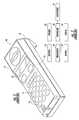
- FIG. 3is a perspective view of a conventional planar inverted-F antenna.
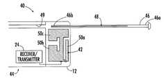
- FIGS. 4A-4Bare cutaway lateral views of a communications device having an antenna system according to an embodiment of the present invention that includes an internal inverted-F antenna and an elongated antenna member.
- the retractable antenna memberis in an extended position in FIG. 4 A and is in a retracted position in FIG. 4 B.
- the internal inverted-F antenna and a conductive element in the elongated antenna memberare capacitively coupled when the elongated antenna member is in the extended position of FIG. 4 A.
- FIG. 5is an electrical diagram illustrating a conductive element of the elongated antenna member of FIGS. 4A-4B capacitively coupled with an inverted-F antenna, according to an embodiment of the present invention.
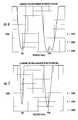
- FIG. 6is a graph of the VSWR performance of the antenna system of FIGS. 4A-4B wherein the elongated antenna member is in an extended position such that the inverted-F antenna and the conductive element of the elongated antenna member are capacitively coupled.
- FIG. 7is a graph of the VSWR performance of the antenna system of FIGS. 4A-4B wherein the retractable antenna is in a retracted position such that the inverted-F antenna and the conductive element of the elongated antenna member are not capacitively coupled.
- the housing 12 of the illustrated radiotelephone 10includes a top portion 13 and a bottom portion 14 connected thereto to form a cavity therein.
- Top and bottom housing portions 13 , 14house a keypad 15 including a plurality of keys 16 , a display 17 , and electronic components (not shown) that enable the radiotelephone 10 to transmit and receive radiotelephone communications signals.
- antenna systems according to the present inventionmay be utilized within various types of wireless communications devices and are not limited to radiotelephones.
- Antenna systems according to the present inventionmay also be used with wireless communications devices which only transmit or receive wireless communications signals.
- Such devices which only receive signalsmay include conventional AM/FM radios or any receiver utilizing an antenna.
- Devices which only transmit signalsmay include remote data input devices.
- FIG. 2A conventional arrangement of electronic components that enable a radiotelephone to transmit and receive radiotelephone communication signals is shown schematically in FIG. 2, and is understood by those skilled in the art of radiotelephone communications.
- An antenna 22 for receiving and transmitting radiotelephone communication signalsis electrically connected to a radio-frequency (RF) transceiver 24 that is further electrically connected to a controller 25 , such as a microprocessor.
- the controller 25is electrically connected to a speaker 26 that transmits a remote signal from the controller 25 to a user of a radiotelephone.
- the controller 25is also electrically connected to a microphone 27 that receives a voice signal from a user and transmits the voice signal through the controller 25 and transceiver 24 to a remote device.
- the controller 25is electrically connected to a keypad 15 and display 17 that facilitate radiotelephone operation.
- an antennais a device for transmitting and/or receiving electrical signals.
- a transmitting antennatypically includes a feed assembly that induces or illuminates an aperture or reflecting surface to radiate an electromagnetic field.
- a receiving antennatypically includes an aperture or surface focusing an incident radiation field to a collecting feed, producing an electronic signal proportional to the incident radiation. The amount of power radiated from or received by an antenna may depend on its aperture area and typically is described in terms of gain.
- Voltage Standing Wave Ratiorelates to the impedance match of an antenna feed point with a feed line or transmission line of a communications device, such as a radiotelephone.
- a communications devicesuch as a radiotelephone.
- the impedance of a radiotelephone antennais conventionally matched to the impedance of a transmission line or feed point.
- Conventional radiotelephonestypically employ an antenna which is electrically connected to a transceiver operably associated with a signal processing circuit positioned on an internally disposed printed circuit board.
- the transceiver and the antennaare preferably interconnected such that their respective impedances are substantially “matched,” i.e., electrically tuned to compensate for undesired antenna impedance components to provide a 50 Ohm ( ⁇ ) (or desired) impedance value at the feed point.
- the illustrated antenna 30includes a linear conductive element 32 maintained in spaced apart relationship with a ground plane 34 .
- Conventional inverted-F antennassuch as that illustrated in FIG. 3, derive their name from a resemblance to the letter “F.”
- the conductive element 32is grounded to the ground plane 34 as indicated by 36 .
- An RF connection 37extends from RF circuitry underlying or overlying the ground plane 34 to the conductive element 32 .
- the antenna system 40for use within wireless communication devices such as radiotelephones is illustrated.
- the antenna system 40includes a multi-frequency band antenna 42 disposed within the housing 12 of a radiotelephone 44 .
- the multi-frequency band antenna 42is electrically connected with a transceiver 24 also disposed within the housing 12 and illustrated schematically.
- An elongated antenna member 46 having a free end 46 a and an opposite end 46 bis movably mounted within the housing 12 and is extendible from the housing 12 so as to have an extended position (FIG. 4A) and a retracted position (FIG. 4 B).
- the elongated antenna member 46includes an elongated conductive element 48 that does not extend all the way to the free end 46 a , as illustrated in FIGS. 4A-4B.
- the conductive element 48is capacitively coupled with the multi-frequency band antenna 42 when the elongated antenna member 46 is in the extended position (FIG. 4 A).
- the multi-frequency band antenna 42is electrically isolated from the elongated conductive element 48 when the elongated antenna member is in the retracted position (FIG. 4 B).
- the elongated antenna member 46is configured to slide within an internal passageway or channel 49 formed within the radiotelephone housing 12 .
- Internal channel 49may have various configurations, and preferably is configured such that the elongated antenna member 46 can be maintained at an extended position and can be maintained at a retracted position.
- the multi-frequency band antenna 42is an inverted-F antenna.
- the illustrated inverted-F antenna 42includes a plurality of planar conductive elements 50 a , 50 b , 50 c .
- Each of the planar conductive elements 50 a , 50 b , 50 chas respective opposite first and second sides 51 a , 51 b and is maintained in adjacent, spaced-apart relationship with a ground plane 51 (e.g., a printed circuit board or shield can overlying a printed circuit board) within the housing 12 as illustrated in FIG. 5 .
- a ground plane 51e.g., a printed circuit board or shield can overlying a printed circuit board
- planar conductive elements 50 a - 50 care typically maintained spaced-apart from the ground plane 51 by a distance H 1 , which may be as large as possible, and typically between about 4 millimeters (mm) and about 12 mm.
- a housingis not illustrated in FIG. 5 for clarity.
- a signal feed 54is electrically connected to one of the planar conductive elements 50 a - 50 c and extends outwardly from the first side 51 a , thereof, and electrically connects the inverted-F antenna 42 to a transceiver 24 .
- a ground contact 56also extends outwardly from the first side 51 a of one of the planar conductive elements 50 - 50 c adjacent the signal feed 54 and grounds the inverted-F antenna 42 via the ground plane 51 .
- an inverted-F antennamay be formed on a dielectric substrate, for example by etching a metal layer or layers in a pattern on the dielectric substrate. Also, as would be understood by those of skill in the art, an inverted-F antenna may have one or more conductive elements disposed within a dielectric substrate.
- a dielectric substrate for an inverted-F antennais FR 4 or polyimide, which is well known to those having skill in the art of communications devices. However, various other dielectric materials also may be utilized.
- a dielectric substratehas a dielectric constant between about 2 and about 4. However, it is to be understood that dielectric substrates having different dielectric constants may be utilized.
- a preferred conductive material out of which the various planar conductive elements 50 a - 50 c of the illustrated inverted-F antenna 42 may be formedis copper.
- the various planar conductive elements 50 a - 50 cmay be formed from copper sheet.
- the various planar conductive elements 50 a - 50 cmay be formed from a copper layer on a dielectric substrate.
- planar conductive elements for inverted-F antennas according to the present inventionmay be formed from various conductive materials and are not limited to copper.
- Inverted-F antennasthat may be utilized in antenna systems 40 according to embodiments of the present invention may have various shapes, configurations, and sizes. Exemplary inverted-F antenna shapes and configurations are described and illustrated in a co-pending and co-assigned U.S. Patent Application entitled: “Inverted-F Antennas With Multiple Planar Radiating Elements And Wireless Communicators Incorporating Same”, Attorney Docket No. 8194-390, filed Apr. 4, 2000, which is incorporated herein by reference in its entirety.
- the inverted-F antenna 42is configured to resonate within a first (i.e., low) frequency band having a first central frequency and within a second (i.e., high) frequency band having a second central frequency, wherein the second central frequency is greater than the first central frequency.
- a first (i.e., low) frequency band having a first central frequencyand within a second (i.e., high) frequency band having a second central frequency, wherein the second central frequency is greater than the first central frequency.
- the elongated conductive element 48is configured to resonate as a half-wave monopole antenna when the inverted-F antenna 42 resonates within the first frequency band.
- the elongated conductive element 48is configured to resonate as a full-wave monopole antenna when the inverted-F antenna 42 resonates within the second frequency band.
- FIG. 6illustrates a graph of the VSWR performance of the antenna system of FIGS. 4A-4B wherein the elongated antenna member 46 is in an extended position such that the inverted-F antenna 42 and conductive element 48 of the elongated antenna member 46 are capacitively coupled.
- FIG. 7illustrates a graph of the VSWR performance of the antenna system of FIGS. 4A-4B wherein the elongated antenna member 46 is in a retracted position such that the inverted-F antenna 42 and conductive element 48 of the elongated antenna member 46 are not capacitively coupled.
- the antenna system represented by the graph of FIG. 6resonates around 894 MHz and around 1850 MHz.
- the antenna system represented by the graph of FIG. 7resonates around 860 MHz and around 1900 MHz.
- the frequency bands within which antenna systems 40 according to the present invention may resonatemay be adjusted by changing the shape, length, width, spacing and/or configuration of the conductive elements of the inverted-F antenna 42 and/or the conductive element 48 of the elongated antenna member 46 .
- antenna systems according to the present inventionhave much broader resonance when the elongated antenna member 46 is in the extended position than when in the retracted position.
Landscapes
- Waveguide Aerials (AREA)
- Support Of Aerials (AREA)
Abstract
Description
Claims (26)
Priority Applications (1)
| Application Number | Priority Date | Filing Date | Title |
|---|---|---|---|
| US09/585,514US6225951B1 (en) | 2000-06-01 | 2000-06-01 | Antenna systems having capacitively coupled internal and retractable antennas and wireless communicators incorporating same |
Applications Claiming Priority (1)
| Application Number | Priority Date | Filing Date | Title |
|---|---|---|---|
| US09/585,514US6225951B1 (en) | 2000-06-01 | 2000-06-01 | Antenna systems having capacitively coupled internal and retractable antennas and wireless communicators incorporating same |
Publications (1)
| Publication Number | Publication Date |
|---|---|
| US6225951B1true US6225951B1 (en) | 2001-05-01 |
Family
ID=24341773
Family Applications (1)
| Application Number | Title | Priority Date | Filing Date |
|---|---|---|---|
| US09/585,514Expired - LifetimeUS6225951B1 (en) | 2000-06-01 | 2000-06-01 | Antenna systems having capacitively coupled internal and retractable antennas and wireless communicators incorporating same |
Country Status (1)
| Country | Link |
|---|---|
| US (1) | US6225951B1 (en) |
Cited By (26)
| Publication number | Priority date | Publication date | Assignee | Title |
|---|---|---|---|---|
| US6314275B1 (en)* | 1997-08-19 | 2001-11-06 | Telit Mobile Terminals, S.P.A. | Hand-held transmitting and/or receiving apparatus |
| US6392605B2 (en)* | 2000-02-02 | 2002-05-21 | Nokia Mobile Phones, Limited | Antenna for a handset |
| US6414641B1 (en)* | 1999-11-19 | 2002-07-02 | Allgon Ab | Antenna device |
| US20020123312A1 (en)* | 2001-03-02 | 2002-09-05 | Hayes Gerard James | Antenna systems including internal planar inverted-F Antenna coupled with external radiating element and wireless communicators incorporating same |
| US6452558B1 (en)* | 2000-08-23 | 2002-09-17 | Matsushita Electric Industrial Co., Ltd. | Antenna apparatus and a portable wireless communication apparatus |
| US6496150B1 (en)* | 2001-06-29 | 2002-12-17 | Nokia Corporation | Decoupling between plural antennas for wireless communication device |
| US20030016175A1 (en)* | 2001-06-29 | 2003-01-23 | Ming Zheng | Antenna |
| US6529168B2 (en)* | 2000-10-27 | 2003-03-04 | Filtronic Lk Oy | Double-action antenna |
| US20030076268A1 (en)* | 2001-10-22 | 2003-04-24 | Filtronic Lk Oy | Internal multiband antenna |
| US6646606B2 (en)* | 2000-10-18 | 2003-11-11 | Filtronic Lk Oy | Double-action antenna |
| US20030209264A1 (en)* | 2002-03-21 | 2003-11-13 | Audeen Richetto | Polymer encapsulated micro-thermocouple |
| WO2003079561A3 (en)* | 2002-03-14 | 2003-12-24 | Tantivy Comm Inc | Mobile communication handset with adaptive antenna array |
| US6677907B2 (en)* | 2000-10-31 | 2004-01-13 | Mitsubishi Denki Kabushiki Kaisha | Antenna device and portable terminal |
| US20040150569A1 (en)* | 2002-03-08 | 2004-08-05 | Tantivy Communications, Inc. | Adaptive receive and omnidirectional transmit antenna array |
| EP1387433A4 (en)* | 2001-04-23 | 2005-04-27 | Yokowo Seisakusho Kk | Broad-band antenna for mobile communication |
| US20050179602A1 (en)* | 2004-02-17 | 2005-08-18 | Samsung Electronics Co., Ltd. | Antenna device for portable wireless terminal |
| US20050237247A1 (en)* | 2002-12-02 | 2005-10-27 | Lk Products Oy | Arrangement for connecting additional antenna to radio device |
| US20050248492A1 (en)* | 2004-02-17 | 2005-11-10 | Samsung Electronics Co., Ltd. | Antenna device for portable wireless terminal |
| US20060109083A1 (en)* | 2004-11-24 | 2006-05-25 | Rathus Spencer A | Method and apparatus for accessing electronic data about at least one person of interest |
| US20060181464A1 (en)* | 2003-05-07 | 2006-08-17 | Nedim Erkocevic | Dual-band antenna for a wireless local area network device |
| US20060240785A1 (en)* | 2002-08-29 | 2006-10-26 | Harald Fischer | Transceiver apparatus for use in a multi-frequency communication system, base station of a multi-frequency communication system, method for use of the transceiver apparatus, method of transceiving a multi-frequency signal in a multi-frequency communication system |
| US7725083B1 (en) | 2000-01-05 | 2010-05-25 | Centurion Wireless Technologies, Inc. | Antenna system for a wireless communication device |
| US20110279300A1 (en)* | 2010-05-17 | 2011-11-17 | Mosebrook Donald R | Wireless battery-powered remote control with label serving as antenna element |
| USD756974S1 (en)* | 2014-08-07 | 2016-05-24 | Cardo Systems, Inc. | Communication device |
| US20160270052A1 (en)* | 2015-03-12 | 2016-09-15 | The Boeing Company | Wireless data concentrators for aircraft data networks |
| US10873349B1 (en) | 2019-06-20 | 2020-12-22 | Motorola Solutions, Inc. | Portable communication device with antenna radiation pattern control |
Citations (7)
| Publication number | Priority date | Publication date | Assignee | Title |
|---|---|---|---|---|
| US5434579A (en)* | 1991-01-28 | 1995-07-18 | Mitsubishi Denki Kabushiki Kaisha | Inverted F antenna with non-contact feeding |
| US5777586A (en)* | 1993-03-17 | 1998-07-07 | Luxon; Norval N. | Radiation shielding and range extending antenna assembly |
| US5812097A (en)* | 1996-04-30 | 1998-09-22 | Qualcomm Incorporated | Dual band antenna |
| US5952975A (en)* | 1994-03-08 | 1999-09-14 | Telital R&D Denmark A/S | Hand-held transmitting and/or receiving apparatus |
| US6075489A (en)* | 1998-09-09 | 2000-06-13 | Centurion Intl., Inc. | Collapsible antenna |
| US6097339A (en)* | 1998-02-23 | 2000-08-01 | Qualcomm Incorporated | Substrate antenna |
| US6137998A (en)* | 1997-12-19 | 2000-10-24 | Ericsson Inc. | Shielding for radiotelephones with retractable antennas |
- 2000
- 2000-06-01USUS09/585,514patent/US6225951B1/ennot_activeExpired - Lifetime
Patent Citations (8)
| Publication number | Priority date | Publication date | Assignee | Title |
|---|---|---|---|---|
| US5434579A (en)* | 1991-01-28 | 1995-07-18 | Mitsubishi Denki Kabushiki Kaisha | Inverted F antenna with non-contact feeding |
| US5684492A (en)* | 1991-01-28 | 1997-11-04 | Mitsubishi Denki Kabushiki Kaisha | Antenna device having a band pass filter |
| US5777586A (en)* | 1993-03-17 | 1998-07-07 | Luxon; Norval N. | Radiation shielding and range extending antenna assembly |
| US5952975A (en)* | 1994-03-08 | 1999-09-14 | Telital R&D Denmark A/S | Hand-held transmitting and/or receiving apparatus |
| US5812097A (en)* | 1996-04-30 | 1998-09-22 | Qualcomm Incorporated | Dual band antenna |
| US6137998A (en)* | 1997-12-19 | 2000-10-24 | Ericsson Inc. | Shielding for radiotelephones with retractable antennas |
| US6097339A (en)* | 1998-02-23 | 2000-08-01 | Qualcomm Incorporated | Substrate antenna |
| US6075489A (en)* | 1998-09-09 | 2000-06-13 | Centurion Intl., Inc. | Collapsible antenna |
Cited By (44)
| Publication number | Priority date | Publication date | Assignee | Title |
|---|---|---|---|---|
| US6314275B1 (en)* | 1997-08-19 | 2001-11-06 | Telit Mobile Terminals, S.P.A. | Hand-held transmitting and/or receiving apparatus |
| US6414641B1 (en)* | 1999-11-19 | 2002-07-02 | Allgon Ab | Antenna device |
| US7725083B1 (en) | 2000-01-05 | 2010-05-25 | Centurion Wireless Technologies, Inc. | Antenna system for a wireless communication device |
| US6392605B2 (en)* | 2000-02-02 | 2002-05-21 | Nokia Mobile Phones, Limited | Antenna for a handset |
| US6452558B1 (en)* | 2000-08-23 | 2002-09-17 | Matsushita Electric Industrial Co., Ltd. | Antenna apparatus and a portable wireless communication apparatus |
| US6646606B2 (en)* | 2000-10-18 | 2003-11-11 | Filtronic Lk Oy | Double-action antenna |
| US6529168B2 (en)* | 2000-10-27 | 2003-03-04 | Filtronic Lk Oy | Double-action antenna |
| US6677907B2 (en)* | 2000-10-31 | 2004-01-13 | Mitsubishi Denki Kabushiki Kaisha | Antenna device and portable terminal |
| US20020123312A1 (en)* | 2001-03-02 | 2002-09-05 | Hayes Gerard James | Antenna systems including internal planar inverted-F Antenna coupled with external radiating element and wireless communicators incorporating same |
| EP1387433A4 (en)* | 2001-04-23 | 2005-04-27 | Yokowo Seisakusho Kk | Broad-band antenna for mobile communication |
| US6496150B1 (en)* | 2001-06-29 | 2002-12-17 | Nokia Corporation | Decoupling between plural antennas for wireless communication device |
| US20030016175A1 (en)* | 2001-06-29 | 2003-01-23 | Ming Zheng | Antenna |
| US7061430B2 (en)* | 2001-06-29 | 2006-06-13 | Nokia Corporation | Antenna |
| US20030076268A1 (en)* | 2001-10-22 | 2003-04-24 | Filtronic Lk Oy | Internal multiband antenna |
| US6759989B2 (en)* | 2001-10-22 | 2004-07-06 | Filtronic Lk Oy | Internal multiband antenna |
| US20040150569A1 (en)* | 2002-03-08 | 2004-08-05 | Tantivy Communications, Inc. | Adaptive receive and omnidirectional transmit antenna array |
| US6873293B2 (en) | 2002-03-08 | 2005-03-29 | Ipr Licensing, Inc. | Adaptive receive and omnidirectional transmit antenna array |
| US20060211374A1 (en)* | 2002-03-08 | 2006-09-21 | Proctor James A Jr | Adaptive receive and omnidirectional transmit antenna array |
| US20050192059A1 (en)* | 2002-03-08 | 2005-09-01 | Ipr Licensing, Inc. | Adaptive receive and omnidirectional transmit antenna array |
| US7034759B2 (en) | 2002-03-08 | 2006-04-25 | Ipr Licensing, Inc. | Adaptive receive and omnidirectional transmit antenna array |
| US20070152892A1 (en)* | 2002-03-14 | 2007-07-05 | Ipr Licensing, Inc. | Mobile communication handset with adaptive antenna array |
| US6876331B2 (en) | 2002-03-14 | 2005-04-05 | Ipr Licensing, Inc. | Mobile communication handset with adaptive antenna array |
| US7530180B2 (en) | 2002-03-14 | 2009-05-12 | Ipr Licensing, Inc. | Mobile communication handset with adaptive antenna array |
| WO2003079561A3 (en)* | 2002-03-14 | 2003-12-24 | Tantivy Comm Inc | Mobile communication handset with adaptive antenna array |
| US20050156797A1 (en)* | 2002-03-14 | 2005-07-21 | Ipr Licensing, Inc. | Mobile communication handset with adaptive antenna array |
| US7190313B2 (en) | 2002-03-14 | 2007-03-13 | Ipr Licensing, Inc. | Mobile communication handset with adaptive antenna array |
| US20030209264A1 (en)* | 2002-03-21 | 2003-11-13 | Audeen Richetto | Polymer encapsulated micro-thermocouple |
| US7583934B2 (en) | 2002-08-29 | 2009-09-01 | Nxp B.V. | Transceiver apparatus for use in a multi-frequency communication system, base station of a multi-frequency communication system, method for use of the transceiver apparatus, method of transceiving a multi-frequency signal in a multi-frequency communication system |
| US20060240785A1 (en)* | 2002-08-29 | 2006-10-26 | Harald Fischer | Transceiver apparatus for use in a multi-frequency communication system, base station of a multi-frequency communication system, method for use of the transceiver apparatus, method of transceiving a multi-frequency signal in a multi-frequency communication system |
| US7081857B2 (en)* | 2002-12-02 | 2006-07-25 | Lk Products Oy | Arrangement for connecting additional antenna to radio device |
| US20050237247A1 (en)* | 2002-12-02 | 2005-10-27 | Lk Products Oy | Arrangement for connecting additional antenna to radio device |
| US7358902B2 (en)* | 2003-05-07 | 2008-04-15 | Agere Systems Inc. | Dual-band antenna for a wireless local area network device |
| US20060181464A1 (en)* | 2003-05-07 | 2006-08-17 | Nedim Erkocevic | Dual-band antenna for a wireless local area network device |
| US7233293B2 (en) | 2004-02-17 | 2007-06-19 | Samsung Electronics Co., Ltd. | Antenna device for portable wireless terminal |
| US20050179602A1 (en)* | 2004-02-17 | 2005-08-18 | Samsung Electronics Co., Ltd. | Antenna device for portable wireless terminal |
| US7106260B2 (en)* | 2004-02-17 | 2006-09-12 | Samsung Electronics Co., Ltd. | Antenna device for portable wireless terminal |
| US20050248492A1 (en)* | 2004-02-17 | 2005-11-10 | Samsung Electronics Co., Ltd. | Antenna device for portable wireless terminal |
| US20060109083A1 (en)* | 2004-11-24 | 2006-05-25 | Rathus Spencer A | Method and apparatus for accessing electronic data about at least one person of interest |
| US20110279300A1 (en)* | 2010-05-17 | 2011-11-17 | Mosebrook Donald R | Wireless battery-powered remote control with label serving as antenna element |
| US8471779B2 (en)* | 2010-05-17 | 2013-06-25 | Lutron Electronics Co., Inc. | Wireless battery-powered remote control with label serving as antenna element |
| USD756974S1 (en)* | 2014-08-07 | 2016-05-24 | Cardo Systems, Inc. | Communication device |
| US20160270052A1 (en)* | 2015-03-12 | 2016-09-15 | The Boeing Company | Wireless data concentrators for aircraft data networks |
| US9521678B2 (en)* | 2015-03-12 | 2016-12-13 | The Boeing Company | Wireless data concentrators for aircraft data networks |
| US10873349B1 (en) | 2019-06-20 | 2020-12-22 | Motorola Solutions, Inc. | Portable communication device with antenna radiation pattern control |
Similar Documents
| Publication | Publication Date | Title |
|---|---|---|
| US6268831B1 (en) | Inverted-f antennas with multiple planar radiating elements and wireless communicators incorporating same | |
| US6380903B1 (en) | Antenna systems including internal planar inverted-F antennas coupled with retractable antennas and wireless communicators incorporating same | |
| US6225951B1 (en) | Antenna systems having capacitively coupled internal and retractable antennas and wireless communicators incorporating same | |
| US6218992B1 (en) | Compact, broadband inverted-F antennas with conductive elements and wireless communicators incorporating same | |
| US6204826B1 (en) | Flat dual frequency band antennas for wireless communicators | |
| US6529749B1 (en) | Convertible dipole/inverted-F antennas and wireless communicators incorporating the same | |
| US6424300B1 (en) | Notch antennas and wireless communicators incorporating same | |
| US6204819B1 (en) | Convertible loop/inverted-f antennas and wireless communicators incorporating the same | |
| US6662028B1 (en) | Multiple frequency inverted-F antennas having multiple switchable feed points and wireless communicators incorporating the same | |
| US6229487B1 (en) | Inverted-F antennas having non-linear conductive elements and wireless communicators incorporating the same | |
| US6124831A (en) | Folded dual frequency band antennas for wireless communicators | |
| US6198442B1 (en) | Multiple frequency band branch antennas for wireless communicators | |
| US6943733B2 (en) | Multi-band planar inverted-F antennas including floating parasitic elements and wireless terminals incorporating the same | |
| US6903686B2 (en) | Multi-branch planar antennas having multiple resonant frequency bands and wireless terminals incorporating the same | |
| JP4132669B2 (en) | Dual-band diversity antenna with parasitic radiating elements | |
| US6980154B2 (en) | Planar inverted F antennas including current nulls between feed and ground couplings and related communications devices | |
| US6184836B1 (en) | Dual band antenna having mirror image meandering segments and wireless communicators incorporating same | |
| EP1368855B1 (en) | Antenna arrangement | |
| US6563466B2 (en) | Multi-frequency band inverted-F antennas with coupled branches and wireless communicators incorporating same | |
| US6700540B2 (en) | Antennas having multiple resonant frequency bands and wireless terminals incorporating the same | |
| US8339321B2 (en) | Antenna device and portable radio apparatus | |
| EP1750323A1 (en) | Multi-band antenna device for radio communication terminal and radio communication terminal comprising the multi-band antenna device | |
| EP2381529B1 (en) | Communications structures including antennas with separate antenna branches coupled to feed and ground conductors | |
| WO1999063616A1 (en) | Non-protruding dual-band antenna for communications device | |
| US20020123312A1 (en) | Antenna systems including internal planar inverted-F Antenna coupled with external radiating element and wireless communicators incorporating same |
Legal Events
| Date | Code | Title | Description |
|---|---|---|---|
| AS | Assignment | Owner name:TELEFONAKTIEBOLAGET L.M. ERICSSON, SWEDEN Free format text:ASSIGNMENT OF ASSIGNORS INTEREST;ASSIGNORS:HOLSHOUSER, HOWARD E.;SANFORD, GARY G.;REEL/FRAME:010843/0806 Effective date:20000526 | |
| STCF | Information on status: patent grant | Free format text:PATENTED CASE | |
| FPAY | Fee payment | Year of fee payment:4 | |
| FPAY | Fee payment | Year of fee payment:8 | |
| FPAY | Fee payment | Year of fee payment:12 | |
| AS | Assignment | Owner name:HIGHBRIDGE PRINCIPAL STRATEGIES, LLC (AS COLLATERA Free format text:LIEN;ASSIGNOR:OPTIS CELLULAR TECHNOLOGY, LLC;REEL/FRAME:031866/0697 Effective date:20131219 | |
| AS | Assignment | Owner name:WILMINGTON TRUST, NATIONAL ASSOCIATION (AS COLLATE Free format text:SECURITY AGREEMENT;ASSIGNOR:OPTIS CELLULAR TECHNOLOGY, LLC;REEL/FRAME:032167/0406 Effective date:20131219 | |
| AS | Assignment | Owner name:OPTIS CELLULAR TECHNOLOGY, LLC, TEXAS Free format text:ASSIGNMENT OF ASSIGNORS INTEREST;ASSIGNOR:CLUSTER LLC;REEL/FRAME:032326/0402 Effective date:20131219 Owner name:CLUSTER LLC, DELAWARE Free format text:ASSIGNMENT OF ASSIGNORS INTEREST;ASSIGNOR:TELEFONAKTIEBOLAGET L M ERICSSON (PUBL);REEL/FRAME:032326/0219 Effective date:20131219 | |
| AS | Assignment | Owner name:HIGHBRIDGE PRINCIPAL STRATEGIES, LLC, AS COLLATERA Free format text:ASSIGNMENT OF ASSIGNORS INTEREST;ASSIGNOR:OPTIS CELLULAR TECHNOLOGY, LLC;REEL/FRAME:032786/0546 Effective date:20140424 | |
| AS | Assignment | Owner name:HIGHBRIDGE PRINCIPAL STRATEGIES, LLC, AS COLLATERA Free format text:CORRECTIVE ASSIGNMENT TO CORRECT THE NATURE OF CONVEYANCE TO READ "SECURITY INTEREST" PREVIOUSLY RECORDED ON REEL 032786 FRAME 0546. ASSIGNOR(S) HEREBY CONFIRMS THE SECURITY INTEREST;ASSIGNOR:OPTIS CELLULAR TECHNOLOGY, LLC;REEL/FRAME:033281/0216 Effective date:20140424 | |
| AS | Assignment | Owner name:OPTIS CELLULAR TECHNOLOGY, LLC, TEXAS Free format text:RELEASE BY SECURED PARTY;ASSIGNOR:HPS INVESTMENT PARTNERS, LLC;REEL/FRAME:039359/0916 Effective date:20160711 |