US6225153B1 - Universal charge port connector for electric vehicles - Google Patents
Universal charge port connector for electric vehiclesDownload PDFInfo
- Publication number
- US6225153B1 US6225153B1US09/275,620US27562099AUS6225153B1US 6225153 B1US6225153 B1US 6225153B1US 27562099 AUS27562099 AUS 27562099AUS 6225153 B1US6225153 B1US 6225153B1
- Authority
- US
- United States
- Prior art keywords
- male
- connector
- housing
- female
- switch
- Prior art date
- Legal status (The legal status is an assumption and is not a legal conclusion. Google has not performed a legal analysis and makes no representation as to the accuracy of the status listed.)
- Expired - Lifetime
Links
Images


Classifications
- H—ELECTRICITY
- H01—ELECTRIC ELEMENTS
- H01R—ELECTRICALLY-CONDUCTIVE CONNECTIONS; STRUCTURAL ASSOCIATIONS OF A PLURALITY OF MUTUALLY-INSULATED ELECTRICAL CONNECTING ELEMENTS; COUPLING DEVICES; CURRENT COLLECTORS
- H01R29/00—Coupling parts for selective co-operation with a counterpart in different ways to establish different circuits, e.g. for voltage selection, for series-parallel selection, programmable connectors
- B—PERFORMING OPERATIONS; TRANSPORTING
- B60—VEHICLES IN GENERAL
- B60L—PROPULSION OF ELECTRICALLY-PROPELLED VEHICLES; SUPPLYING ELECTRIC POWER FOR AUXILIARY EQUIPMENT OF ELECTRICALLY-PROPELLED VEHICLES; ELECTRODYNAMIC BRAKE SYSTEMS FOR VEHICLES IN GENERAL; MAGNETIC SUSPENSION OR LEVITATION FOR VEHICLES; MONITORING OPERATING VARIABLES OF ELECTRICALLY-PROPELLED VEHICLES; ELECTRIC SAFETY DEVICES FOR ELECTRICALLY-PROPELLED VEHICLES
- B60L50/00—Electric propulsion with power supplied within the vehicle
- B60L50/50—Electric propulsion with power supplied within the vehicle using propulsion power supplied by batteries or fuel cells
- B60L50/60—Electric propulsion with power supplied within the vehicle using propulsion power supplied by batteries or fuel cells using power supplied by batteries
- B60L50/66—Arrangements of batteries
- B—PERFORMING OPERATIONS; TRANSPORTING
- B60—VEHICLES IN GENERAL
- B60L—PROPULSION OF ELECTRICALLY-PROPELLED VEHICLES; SUPPLYING ELECTRIC POWER FOR AUXILIARY EQUIPMENT OF ELECTRICALLY-PROPELLED VEHICLES; ELECTRODYNAMIC BRAKE SYSTEMS FOR VEHICLES IN GENERAL; MAGNETIC SUSPENSION OR LEVITATION FOR VEHICLES; MONITORING OPERATING VARIABLES OF ELECTRICALLY-PROPELLED VEHICLES; ELECTRIC SAFETY DEVICES FOR ELECTRICALLY-PROPELLED VEHICLES
- B60L53/00—Methods of charging batteries, specially adapted for electric vehicles; Charging stations or on-board charging equipment therefor; Exchange of energy storage elements in electric vehicles
- B60L53/10—Methods of charging batteries, specially adapted for electric vehicles; Charging stations or on-board charging equipment therefor; Exchange of energy storage elements in electric vehicles characterised by the energy transfer between the charging station and the vehicle
- B60L53/14—Conductive energy transfer
- B60L53/16—Connectors, e.g. plugs or sockets, specially adapted for charging electric vehicles
- H—ELECTRICITY
- H01—ELECTRIC ELEMENTS
- H01R—ELECTRICALLY-CONDUCTIVE CONNECTIONS; STRUCTURAL ASSOCIATIONS OF A PLURALITY OF MUTUALLY-INSULATED ELECTRICAL CONNECTING ELEMENTS; COUPLING DEVICES; CURRENT COLLECTORS
- H01R13/00—Details of coupling devices of the kinds covered by groups H01R12/70 or H01R24/00 - H01R33/00
- H01R13/62—Means for facilitating engagement or disengagement of coupling parts or for holding them in engagement
- H01R13/627—Snap or like fastening
- H01R13/6271—Latching means integral with the housing
- H01R13/6272—Latching means integral with the housing comprising a single latching arm
- H—ELECTRICITY
- H01—ELECTRIC ELEMENTS
- H01R—ELECTRICALLY-CONDUCTIVE CONNECTIONS; STRUCTURAL ASSOCIATIONS OF A PLURALITY OF MUTUALLY-INSULATED ELECTRICAL CONNECTING ELEMENTS; COUPLING DEVICES; CURRENT COLLECTORS
- H01R13/00—Details of coupling devices of the kinds covered by groups H01R12/70 or H01R24/00 - H01R33/00
- H01R13/62—Means for facilitating engagement or disengagement of coupling parts or for holding them in engagement
- H01R13/629—Additional means for facilitating engagement or disengagement of coupling parts, e.g. aligning or guiding means, levers, gas pressure electrical locking indicators, manufacturing tolerances
- H01R13/62933—Comprising exclusively pivoting lever
- H—ELECTRICITY
- H01—ELECTRIC ELEMENTS
- H01R—ELECTRICALLY-CONDUCTIVE CONNECTIONS; STRUCTURAL ASSOCIATIONS OF A PLURALITY OF MUTUALLY-INSULATED ELECTRICAL CONNECTING ELEMENTS; COUPLING DEVICES; CURRENT COLLECTORS
- H01R13/00—Details of coupling devices of the kinds covered by groups H01R12/70 or H01R24/00 - H01R33/00
- H01R13/66—Structural association with built-in electrical component
- H01R13/70—Structural association with built-in electrical component with built-in switch
- H01R13/703—Structural association with built-in electrical component with built-in switch operated by engagement or disengagement of coupling parts, e.g. dual-continuity coupling part
- H01R13/7036—Structural association with built-in electrical component with built-in switch operated by engagement or disengagement of coupling parts, e.g. dual-continuity coupling part the switch being in series with coupling part, e.g. dead coupling, explosion proof coupling
- H01R13/7038—Structural association with built-in electrical component with built-in switch operated by engagement or disengagement of coupling parts, e.g. dual-continuity coupling part the switch being in series with coupling part, e.g. dead coupling, explosion proof coupling making use of a remote controlled switch, e.g. relais, solid state switch activated by the engagement of the coupling parts
- B—PERFORMING OPERATIONS; TRANSPORTING
- B60—VEHICLES IN GENERAL
- B60L—PROPULSION OF ELECTRICALLY-PROPELLED VEHICLES; SUPPLYING ELECTRIC POWER FOR AUXILIARY EQUIPMENT OF ELECTRICALLY-PROPELLED VEHICLES; ELECTRODYNAMIC BRAKE SYSTEMS FOR VEHICLES IN GENERAL; MAGNETIC SUSPENSION OR LEVITATION FOR VEHICLES; MONITORING OPERATING VARIABLES OF ELECTRICALLY-PROPELLED VEHICLES; ELECTRIC SAFETY DEVICES FOR ELECTRICALLY-PROPELLED VEHICLES
- B60L2270/00—Problem solutions or means not otherwise provided for
- B60L2270/30—Preventing theft during charging
- B60L2270/32—Preventing theft during charging of electricity
- B—PERFORMING OPERATIONS; TRANSPORTING
- B60—VEHICLES IN GENERAL
- B60L—PROPULSION OF ELECTRICALLY-PROPELLED VEHICLES; SUPPLYING ELECTRIC POWER FOR AUXILIARY EQUIPMENT OF ELECTRICALLY-PROPELLED VEHICLES; ELECTRODYNAMIC BRAKE SYSTEMS FOR VEHICLES IN GENERAL; MAGNETIC SUSPENSION OR LEVITATION FOR VEHICLES; MONITORING OPERATING VARIABLES OF ELECTRICALLY-PROPELLED VEHICLES; ELECTRIC SAFETY DEVICES FOR ELECTRICALLY-PROPELLED VEHICLES
- B60L2270/00—Problem solutions or means not otherwise provided for
- B60L2270/30—Preventing theft during charging
- B60L2270/34—Preventing theft during charging of parts
- H—ELECTRICITY
- H01—ELECTRIC ELEMENTS
- H01R—ELECTRICALLY-CONDUCTIVE CONNECTIONS; STRUCTURAL ASSOCIATIONS OF A PLURALITY OF MUTUALLY-INSULATED ELECTRICAL CONNECTING ELEMENTS; COUPLING DEVICES; CURRENT COLLECTORS
- H01R13/00—Details of coupling devices of the kinds covered by groups H01R12/70 or H01R24/00 - H01R33/00
- H01R13/44—Means for preventing access to live contacts
- H01R13/447—Shutter or cover plate
- H—ELECTRICITY
- H01—ELECTRIC ELEMENTS
- H01R—ELECTRICALLY-CONDUCTIVE CONNECTIONS; STRUCTURAL ASSOCIATIONS OF A PLURALITY OF MUTUALLY-INSULATED ELECTRICAL CONNECTING ELEMENTS; COUPLING DEVICES; CURRENT COLLECTORS
- H01R13/00—Details of coupling devices of the kinds covered by groups H01R12/70 or H01R24/00 - H01R33/00
- H01R13/46—Bases; Cases
- H01R13/53—Bases or cases for heavy duty; Bases or cases for high voltage with means for preventing corona or arcing
- Y—GENERAL TAGGING OF NEW TECHNOLOGICAL DEVELOPMENTS; GENERAL TAGGING OF CROSS-SECTIONAL TECHNOLOGIES SPANNING OVER SEVERAL SECTIONS OF THE IPC; TECHNICAL SUBJECTS COVERED BY FORMER USPC CROSS-REFERENCE ART COLLECTIONS [XRACs] AND DIGESTS
- Y02—TECHNOLOGIES OR APPLICATIONS FOR MITIGATION OR ADAPTATION AGAINST CLIMATE CHANGE
- Y02T—CLIMATE CHANGE MITIGATION TECHNOLOGIES RELATED TO TRANSPORTATION
- Y02T10/00—Road transport of goods or passengers
- Y02T10/60—Other road transportation technologies with climate change mitigation effect
- Y02T10/70—Energy storage systems for electromobility, e.g. batteries
- Y—GENERAL TAGGING OF NEW TECHNOLOGICAL DEVELOPMENTS; GENERAL TAGGING OF CROSS-SECTIONAL TECHNOLOGIES SPANNING OVER SEVERAL SECTIONS OF THE IPC; TECHNICAL SUBJECTS COVERED BY FORMER USPC CROSS-REFERENCE ART COLLECTIONS [XRACs] AND DIGESTS
- Y02—TECHNOLOGIES OR APPLICATIONS FOR MITIGATION OR ADAPTATION AGAINST CLIMATE CHANGE
- Y02T—CLIMATE CHANGE MITIGATION TECHNOLOGIES RELATED TO TRANSPORTATION
- Y02T10/00—Road transport of goods or passengers
- Y02T10/60—Other road transportation technologies with climate change mitigation effect
- Y02T10/7072—Electromobility specific charging systems or methods for batteries, ultracapacitors, supercapacitors or double-layer capacitors
- Y—GENERAL TAGGING OF NEW TECHNOLOGICAL DEVELOPMENTS; GENERAL TAGGING OF CROSS-SECTIONAL TECHNOLOGIES SPANNING OVER SEVERAL SECTIONS OF THE IPC; TECHNICAL SUBJECTS COVERED BY FORMER USPC CROSS-REFERENCE ART COLLECTIONS [XRACs] AND DIGESTS
- Y02—TECHNOLOGIES OR APPLICATIONS FOR MITIGATION OR ADAPTATION AGAINST CLIMATE CHANGE
- Y02T—CLIMATE CHANGE MITIGATION TECHNOLOGIES RELATED TO TRANSPORTATION
- Y02T90/00—Enabling technologies or technologies with a potential or indirect contribution to GHG emissions mitigation
- Y02T90/10—Technologies relating to charging of electric vehicles
- Y02T90/14—Plug-in electric vehicles
- Y—GENERAL TAGGING OF NEW TECHNOLOGICAL DEVELOPMENTS; GENERAL TAGGING OF CROSS-SECTIONAL TECHNOLOGIES SPANNING OVER SEVERAL SECTIONS OF THE IPC; TECHNICAL SUBJECTS COVERED BY FORMER USPC CROSS-REFERENCE ART COLLECTIONS [XRACs] AND DIGESTS
- Y10—TECHNICAL SUBJECTS COVERED BY FORMER USPC
- Y10S—TECHNICAL SUBJECTS COVERED BY FORMER USPC CROSS-REFERENCE ART COLLECTIONS [XRACs] AND DIGESTS
- Y10S439/00—Electrical connectors
- Y10S439/911—Safety, e.g. electrical disconnection required before opening housing
Definitions
- the present inventionrelates to electrical connectors and, more particularly, to electrical connectors utilized in electric vehicles for supplying current to recharge the vehicle batteries.
- connectorsused in the automotive field and elsewhere, and particularly in electrical vehicles, must be capable of withstanding heavy current loads.
- connectorsare used to connect the battery pack of the electric vehicle to high or low voltage distribution boxes and to connect the high or low voltage distribution boxes to the charging port and to the motor of the vehicle.
- the environment in which these connectors are usedplaces a great deal of both mechanical and thermal stress on the connectors.
- the mating members of these connectorsmust be securely connected so that the connector does not fail during normal usage. Additionally, the connectors must be relatively easy to mate, that is, one member of the connector be readily insertable into its mating member. It is also desirable for the connector to handle both AC as well as DC current so that one connector may be used for both power sources. It is also desirable that the connector house control circuits for prohibiting arcing between the positive and negative contacts within the connector. Further, the connector should prohibit unauthorized connector separation during charging of the vehicle batteries. Furthermore, the connector should prohibit the vehicle from moving during the charging of the batteries.
- the present inventionprovides a connector capable of conducting both high and low voltages from a DC or AC power source. It is also an object to have a connector which is provided with both AC and DC contacts so that, depending upon the power source, the contacts can accommodate the power source. Further, the present invention provides a mechanism which prohibits unauthorized separation of the connectors during charging of the vehicle batteries. Another object is that the present invention provides a connector which terminates power to the connector prior to separation of the male and female members to prohibit arcing. The present invention also, during charging, cuts off the power in the vehicle so that it cannot be driven away during charging. Further, the present invention provides handles on the connectors to enable easy manipulation of the connectors to couple the male and female connectors together.
- an electrical connector assemblycomprises a male connector having a housing with a first pair and second pair of electrical contacts in the housing.
- a female connectorhas a housing with a first pair of electrical contacts to electrically couple with the male connector first pair of electrical contacts.
- the female connectoralso includes a second pair of electrical contacts to electrically couple with the male connector second pair of electrical contacts.
- One of the pair of electrical contactsis for conducting DC current and the other of the pairs of electrical contacts is for conducting AC current.
- the connector assemblyincludes a common ground for both pairs of electrical contacts.
- the male connectorhas an elongated housing with a first and second handle. Also, a latching mechanism is coupled with the male housing to secure the male and female housings together. Further, the male housing is capable of coupling with a plurality of members to receive a plurality of different sized power sources.
- the female housinghas a first member with a cup portion which defines a cavity to receive the male connector.
- the cuphas a base with a plurality of apertures to receive the pairs of electrical contacts.
- a collar portionextends from the cup portion to receive electrical contacts.
- a second membercouples with the collar member of the first member.
- the second memberhas a plurality of electrical contact holding members to receive the electrical contacts and align the electrical contacts to position the contacts into the apertures.
- the female housingincludes a third member which is coupled with the first member.
- the third memberhas a ring member with a plurality of apertures enabling securement with the vehicle body.
- a dooris coupled with the third member to cover the ring opening.
- a capis coupled with the female housing when the male and female housings are disconnected.
- the cupincludes a rotatable member to secure the cap with the female housing. The rotatable member is biased to return to its original position upon removal from the female housing.
- the electrical connector assemblycomprises a male connector having a housing and electrical contacts in the housing for conducting AC or DC current.
- the male connectorhas a housing to couple with the female connector. Electrical contacts are in the female housing to couple with the electrical contacts and the male connector.
- a mechanism to eliminate current arcing during disconnection of the male and female connectorsis coupled with at least one of the male or female connectors.
- the mechanismincludes a switch coupled with a power source for the connector assembly. The switch terminates current flow prior to disconnection of the male and female connectors.
- the mechanismhas a release lever coupled with the switch to activate the switch. Also, the release lever is coupled with a latch which releasably locks the male and female connectors in a coupled position.
- an electrical connectorcomprises a male connector with a housing having electrical contacts in the housing to conduct AC or DC current.
- a female connectorhas a housing to couple with the male connector housing. Electrical contacts are in the female housing to couple with the electrical contacts in the male housing.
- the male and female connectorsare coupled between a power source and a rechargeable power user.
- a mechanism to terminate power to the rechargeable power user prohibiting use of the rechargeable power user during chargingis an electric vehicle including electric batteries.
- the mechanismhas a switch to cut off power in the vehicle so that the vehicle is disabled during charging.
- the mechanismis coupled with the connector on the rechargeable power user.
- the female housinghas a cover to cover the electrical contacts in a disconnected position. The cover activates the mechanism upon opening of the cover to enable connection with the male connector.
- the electrical connector assemblycomprises a male connector with a housing having electrical contacts in the housing to conduct AC or DC current.
- a female conductorhas a housing to couple with the male housing. Electrical contacts are in the female housing to couple with the male electrical contacts.
- a latch mechanismreleasably couples the male and female connectors together.
- a lock mechanismis coupled with the latch mechanism to prohibit unauthorized disconnection of the male and female connectors in a coupled position.
- the latch mechanismhas a trigger pivoted with a catch. The trigger releases the catch which holds the male and female connectors together.
- the trigger and catchare housed in the male connector housing with the catch adapted to couple with the female connector housing.
- the housinghas a trigger guard with an opening. The trigger is in the opening which enables access to the trigger.
- the lock mechanismincludes a member to prohibit pivoting of the trigger.
- the lock mechanismincludes an aperture in the trigger guard with the member in the aperture. The member is ordinarily a padlock.
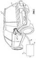
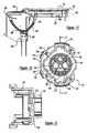
- FIG. 1is a perspective view of a connector assembly in accordance with the present invention on a vehicle
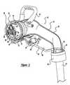
- FIG. 2is an exploded perspective view of the connector of FIG. 1;
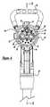
- FIG. 3is a partial cross-section view of the male connector of FIG. 2;
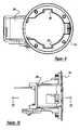
- FIG. 4is an elevation view of the male connector of FIG. 2;
- FIG. 5is a cross-section view of FIG. 4 along line 5 — 5 thereof;
- FIG. 6is an enlarged view of FIG. 5 within circle 6 ;
- FIG. 7is a perspective view of the female connector of FIG. 2;
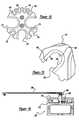
- FIG. 8is an exploded perspective view of FIG. 7;
- FIG. 9is an elevation view of the bezel front
- FIG. 10is an elevation view of the bezel side of FIG. 9;
- FIG. 11is a cross-section view of FIG. 10 through line 11 — 11 thereof;
- FIG. 12is an elevation view of the cup of the female connector of FIG. 8;
- FIG. 13is a cross-section view of FIG. 12 through line 13 — 13 thereof;
- FIG. 14is an elevation view of the contact holder of FIG. 8;
- FIG. 15is an enlarged view of one of the holders of FIG. 14.
- FIG. 16is a cross-section view of the cap cover of FIG. 8 .
- a vehicle 10has a connector assembly 20 to transmit power from a power source 14 to the vehicle 10 .
- the vehicle 10is an electric vehicle including chargeable batteries 16 which are housed within the vehicle.
- the power source 14includes a control box 18 which distributes power via the cord 22 through connector assembly 20 to the vehicle 10 .
- the control box 18may be set up to deliver DC current at about 400 amps at a desired voltage or AC current at about 40 amps at a desired voltage. Ordinarily, if a direct current is flowing, the voltage is high and around 400 volts. If the AC current is flowing, the current is lower, somewhere around 220 volts. Accordingly, the connector assembly 20 is capable of handling both AC and DC currents that are provided from different power sources.
- the connector assembly 20includes a male connector 24 coupled with the wire 22 and a female connector 26 coupled with the vehicle 10 .
- the male connector 24includes a housing 28 having one end 30 connected with the wire 22 and the other end 32 to be coupled with the female housing 26 .
- the housing 28has an elongated U-shape with the ends 30 and 32 defining the legs of the U and a web 34 between the two legs.
- the housingincludes two parts which are coupled together with one another.
- the housinghas two handles 36 and 38 to enable manipulation of the male connector 24 .
- the handle 36acts as a trigger guard for trigger 40 and includes openings 42 and 44 . The openings enable the user to position a hand within the trigger guard handle 36 .
- the handle 38has an overall U-shape and is secured to the housing 28 near the front end 32 .
- the U-shaped handle 38enables the user to use two hands on the connector for easy manipulation to connect with the male 24 and female housing 26 .
- the housing 28houses the trigger 40 which is coupled with a catch 46 .
- the catch 46releasably secures the male and female connectors together.
- the catch 46has a downturned end 48 which secures with the female connector 26 .
- the trigger 40 as well as the catch 46are connected to one another about a pivot 49 in the housing.
- the trigger 40is pivoted in the opening 44 which, in turn, moves the latch 46 in and out of connection with the female connector 26 to release the male connector from the female connector.
- the trigger guard handle 36includes a bore 50 which passes through the trigger guard handle 36 adjacent to the trigger and latch connection.
- the bore 50enables passage of a U member 52 of a padlock 54 so that the trigger 40 can be locked in position during charging of the vehicle batteries.
- the U-member 52 in the boreprohibits the trigger 40 from being moved.
- thisprohibits the latch 46 from moving and releasing the male connector 24 from the female connector 26 .
- the connectors 24 and 26can be effectively locked with one another, prohibiting unauthorized separation of the connector members 24 , 26 during charging.
- the housing 28is hollow to enable wires to pass from the rear end 30 to the front end 32 .
- the rear end 30includes an external thread 56 and an internal circumferential groove 58 .
- the circumferential recess 58receives a flanged end 60 of a strain relief 62 to secure the wire 22 with the housing 28 .
- a nut 64surrounds the strain relief 62 and screws onto the external thread 56 .
- the housingmay receive several different strain reliefs and nuts so that different sized wires may be connected with the housing 28 .
- a contact retaining member 70is positioned in the housing 32 .
- the contact retaining member 70is of an insulated material to prohibit arcing between the positive and negative electrical contacts.
- the contact retaining member 70includes circumferential projection 72 which is received in recess 74 from the housing 28 to retain the contact retaining member 70 in a desired orientation in the housing 28 .
- the contact retaining member 70includes a plurality of apertures to enable passage of electrical contacts.
- Bore 76includes the ground contact 78 .
- Bores 80 and 82receive DC electrical contacts 84 and 86 .
- Bores 88 and 90receive AC electrical contacts (not shown).
- Bores 92 , 94 , 96 and 98receive various types of control lines as will be explained herein.
- the male connector 24may include DC contacts 84 and 86 . However, if the power supply is AC current, then the DC contacts would be removed and AC contacts would be positioned in bores 88 and 90 . Thus, the male connector member 24 is adapted to receive both the AC or DC current contacts. Also, the male connector 24 is adapted to receive both AC or DC current from the power source, depending upon what type of power source is used. However, only one power source, either DC or AC, will be utilized in the male member at one time.
- the female connectorincludes a first cup shaped member 110 , a second contact holding member 112 , and a third ring member 114 which includes a cover 116 .
- the cup shaped member 110has a circumferential wall 120 which terminates at a base 122 and has an opened end with a flange 124 .
- the baseincludes a collar 126 which extends on its opposite side away from the wall 120 .
- the flange 124includes openings 128 with latching fingers 130 positioned in the opening to secure the cup member 110 with the ring 114 .
- the base 122includes a plurality of bores to receive the electrical contacts that are secured on the contact holding member 112 .
- the bore 132receives a common ground 134 which is connected with the ground 78 of the male connector 24 . Bores 136 and 138 receive electrical contacts 140 and 142 .
- Contacts 140 and 142are positive and negative DC contacts and are adapted to couple with the DC electrical contacts 84 and 86 of the male member.
- the bores 144 and 146receive contacts 148 and 150 .
- Electrical contacts 148 and 150are adapted to couple with the AC contacts (not shown) in the male connector 24 .
- Bores 152 , 154 , 156 and 158receive electrical contacts 160 , 162 , 164 and 166 which provide various control circuits through the connector assembly.
- the electrical contact holding member 112includes a plurality of cut-outs to hold the electrical contacts.
- the holding member 112is manufactured from an insulated material and fits into the collar 126 on the cup member 110 . Also, fasteners secure the holding member 112 with the cup shaped member 110 .
- Cut-out 170holds the ground 134 .
- Cut-outs 172 and 174hold the DC electrical contacts 140 and 142 .
- Cut-outs 176 and 178hold the AC electrical contacts 148 and 150 .
- Cut-outs 180 , 182 , 184 and 186hold the contacts 160 , 162 , 164 and 166 .
- All of the cut-outsinclude a bottom arcuate portion 188 which is slightly smaller than the outward parallel wall portions 190 , 192 so that barbs 194 are formed.
- the electrical contactsare pressed and frictionally held by barbs 194 within the holder cut outs as seen in FIG. 14 .
- the mechanism 240includes a switch 241 having lead wires 242 and 244 . Wire 242 goes back to the control box and lead 244 goes to an electrical contact 246 in one of the bores 92 through 98 .
- the switch 241includes an arm 248 which is coupled with the trigger 40 and latch 46 such that upon activation of the trigger 40 , the switch 241 deactivates power from the power source to the vehicle.
- the trigger 40is lifted upward which, in turn, activates switch 241 , which sends a signal to the power source, terminating power to the either AC or DC electrical contacts. This prohibits arcing between the contacts upon removal from the female connector 26 .
- the power sourcewould then be terminated until it is turned on again to recharge the vehicle.
- the mechanism 260includes a switch 262 which is connected to the vehicle control module such that, upon opening of the cover 116 , the switch is activated to de-energize the vehicle.
- the de-energizing of the vehiclecuts off the power such that once the connectors are coupled together, the vehicle cannot be moved. Thus, unauthorized movement of the vehicle cannot be accomplished until charging is complete.
- a cap 270is provided to cover the contacts on the vehicle.
- the cap 270includes a cover portion 272 and a lock portion 274 .
- the cover portion 272is cup shaped and has projecting members 276 and 278 which mate with recesses 277 and 279 in the female cup shaped member 110 .
- the lock portion 274includes a handle 280 and a pair of tabs 282 and 284 .
- a strap 286is connected with the handle for securing the cap 270 with the housing so that when the cap is removed it remains attached to the housing.
- the tabs 282 and 284align with the projecting members 276 and 278 .
- a groove 115is formed between the ring 114 and cup 110 .
- the handle 280is turned wherein the tabs 282 and 284 move within the groove 115 locking the cap 270 in the female connector.
- a spring 288is secured to the cover 274 and cup 272 to bias the cover 274 between positions. See FIGS. 8 and 16. Also, detents are located in the recess for trapping the tabs 282 and 284 in the groove.
- the ring 114includes recesses 292 and 294 which enable passage of the cap projections 276 and 278 .
- a housing 296is secured with the ring 114 .
- the housing 296includes a pivot 298 which couples the cover arm 300 with the housing 296 .
- the cover arm 300is coupled with the cover 116 .
- the cover 116also includes a latch 302 which may be secured with the ring 114 or have a member projecting through the ring to secure the cover in a closed and locked position.
- the housing 296includes mechanism 260 attached thereto. Accordingly, when the cover is in a closed position, an arm tab 304 contacts the switch lever 264 which closes the circuit activating the vehicle enabling it to be moved away. Accordingly, the cover must be shut for the vehicle to run.
- the ring 114is positioned such that the housing 296 is under the vehicle sheet metal and the ring 114 is on the outside of the sheet metal. Fasteners are passed through the holes 306 through the vehicle sheet metal to connect the ring 114 with the vehicle as well as the cup member 110 .
Landscapes
- Engineering & Computer Science (AREA)
- Power Engineering (AREA)
- Transportation (AREA)
- Mechanical Engineering (AREA)
- Life Sciences & Earth Sciences (AREA)
- Sustainable Development (AREA)
- Sustainable Energy (AREA)
- Details Of Connecting Devices For Male And Female Coupling (AREA)
- Electric Propulsion And Braking For Vehicles (AREA)
Abstract
Description
Claims (1)
Priority Applications (1)
| Application Number | Priority Date | Filing Date | Title |
|---|---|---|---|
| US09/275,620US6225153B1 (en) | 1999-03-24 | 1999-03-24 | Universal charge port connector for electric vehicles |
Applications Claiming Priority (1)
| Application Number | Priority Date | Filing Date | Title |
|---|---|---|---|
| US09/275,620US6225153B1 (en) | 1999-03-24 | 1999-03-24 | Universal charge port connector for electric vehicles |
Publications (1)
| Publication Number | Publication Date |
|---|---|
| US6225153B1true US6225153B1 (en) | 2001-05-01 |
Family
ID=23053138
Family Applications (1)
| Application Number | Title | Priority Date | Filing Date |
|---|---|---|---|
| US09/275,620Expired - LifetimeUS6225153B1 (en) | 1999-03-24 | 1999-03-24 | Universal charge port connector for electric vehicles |
Country Status (1)
| Country | Link |
|---|---|
| US (1) | US6225153B1 (en) |
Cited By (46)
| Publication number | Priority date | Publication date | Assignee | Title |
|---|---|---|---|---|
| WO2003032445A1 (en)* | 2001-10-11 | 2003-04-17 | Lear Automotive (Eeds) Spain,S.L. | System and method of preventing electric arcs in connectors that supply power charges and the connector used for same |
| US7404720B1 (en)* | 2007-03-29 | 2008-07-29 | Tesla Motors, Inc. | Electro mechanical connector for use in electrical applications |
| US20090146610A1 (en)* | 2007-12-11 | 2009-06-11 | Antonio Trigiani | Battery management system |
| US20100328057A1 (en)* | 2009-06-24 | 2010-12-30 | Futurewei Technologies, Inc. | Method and Apparatus for Electric Powered Vehicle Recharging Safety |
| FR2947393A1 (en)* | 2009-06-30 | 2010-12-31 | Valeo Securite Habitacle | POWER CONNECTOR FOR RECHARGING AN ELECTRIC VEHICLE |
| US20110034053A1 (en)* | 2008-11-21 | 2011-02-10 | Yazaki Corporation | Charging connector |
| WO2011043804A1 (en)* | 2009-10-08 | 2011-04-14 | Tyco Electronics Corporation | Connector assembly having multi-stage latching sequence |
| CN102097712A (en)* | 2010-12-04 | 2011-06-15 | 张家港友诚科技机电有限公司 | Locking device for anti-pulling mechanism in charging interface |
| WO2011092431A1 (en)* | 2010-01-29 | 2011-08-04 | Renault Sas | Electric base and plug for the mains recharging of the batteries of an electric motor vehicle |
| US20110212645A1 (en)* | 2010-03-01 | 2011-09-01 | Sumitomo Wiring Systems, Ltd. | Charging connector |
| US20120164489A1 (en)* | 2010-12-24 | 2012-06-28 | Wataru Okada | Power source apparatus equipped with a service plug and vehicle carrying that power source apparatus |
| US20120181977A1 (en)* | 2011-01-17 | 2012-07-19 | Kabushiki Kaisha Yaskawa Denki | Charging apparatus and operating tool |
| US20120193929A1 (en)* | 2010-07-23 | 2012-08-02 | Electric Transportation Engineering Corp., dba ECOtality North America | Device to facilitate moving an electrical cable of an electric vehicle charging station and method of providing the same |
| WO2012161295A1 (en)* | 2011-05-20 | 2012-11-29 | Yazaki Corporation | Arc discharge prevention connector |
| US8342893B2 (en) | 2010-07-02 | 2013-01-01 | Lear Corporation | Stamped electrical terminal |
| DE102010041229B4 (en)* | 2009-09-24 | 2013-03-14 | Lear Corporation | Rechargeable handle for hybrid electric vehicle |
| DE102011056590A1 (en)* | 2011-12-19 | 2013-06-20 | Dr.Ing.H.C.F.Porsche Aktiengesellschaft | Charging socket locking system for use in e.g. hybrid car, during maintenance/service procedure, has charging socket cover for latching charging socket by insertion of positioning element into retainer of charging socket cover |
| US20130260595A1 (en)* | 2012-03-27 | 2013-10-03 | Honda Motor Co., Ltd. | Charging device for electrically driven vehicle |
| US8573994B2 (en)* | 2010-11-19 | 2013-11-05 | Delphi Technologies, Inc. | Connector handle for an electric vehicle battery charger |
| US20140322951A1 (en)* | 2012-01-17 | 2014-10-30 | Yazaki Corporation | Electrical connector |
| CN104170183A (en)* | 2012-03-15 | 2014-11-26 | 丰田自动车株式会社 | Extraction device |
| US20150155656A1 (en)* | 2012-08-06 | 2015-06-04 | Yazaki Corporation | Charging connector |
| US20150372421A1 (en)* | 2013-02-14 | 2015-12-24 | Phoenix Contact E-Mobility Gmbh | Locking device for a plug-in connection |
| US20160020555A1 (en)* | 2013-03-28 | 2016-01-21 | Yazaki Corporation | Charging connector |
| JP2016015341A (en)* | 2015-10-16 | 2016-01-28 | 日本航空電子工業株式会社 | Electric connector, electric connector unit, and battery charger for electric automobile |
| JP2017022055A (en)* | 2015-07-14 | 2017-01-26 | 日本航空電子工業株式会社 | Electric connector and jig for recovery |
| US20170062984A1 (en)* | 2015-08-26 | 2017-03-02 | Phoenix Contact E-Mobility Gmbh | Plug-in connector part comprising a locking element |
| DE102017119056A1 (en)* | 2017-08-21 | 2019-02-21 | HARTING Automotive GmbH | Charging connector with actuating means |
| US20190077271A1 (en)* | 2017-09-08 | 2019-03-14 | SparkCharge, Inc. | Electric charging system for electric cars |
| US10944131B2 (en) | 2016-12-16 | 2021-03-09 | Milwaukee Electric Tool Corporation | Battery pack switch |
| US10940984B2 (en)* | 2017-10-31 | 2021-03-09 | Ponticelli Sr Robert Joseph | Battery powered keyless locking cap |
| US11179841B2 (en)* | 2016-12-16 | 2021-11-23 | Milwaukee Electric Tool Corporation | Battery pack interface |
| US11245225B2 (en)* | 2016-04-01 | 2022-02-08 | Harting Electric Gmbh & Co. Kg | Locking device for plug connectors |
| US11251508B2 (en) | 2017-03-24 | 2022-02-15 | Milwaukee Electric Tool Corporation | Terminal configuration for a battery pack |
| US11374528B2 (en) | 2017-06-30 | 2022-06-28 | Milwaukee Electric Tool Corporation | High power battery-powered system |
| US11498444B1 (en) | 2021-12-29 | 2022-11-15 | Beta Air, Llc | System and method for overcurrent protection in an electric vehicle |
| WO2022271920A1 (en)* | 2021-06-24 | 2022-12-29 | Webasto Charging Systems, Inc. | Hotmelt for sealing electric vehicle supply equipment (evse) |
| US11613185B1 (en) | 2021-12-28 | 2023-03-28 | Beta Air, Llc | Charger connector for an electric aircraft |
| US20230198202A1 (en)* | 2021-12-22 | 2023-06-22 | Japan Aviation Electronics Industry, Limited | Charging connector |
| NO20211582A1 (en)* | 2021-12-23 | 2023-06-26 | Defa As | A connector assembly |
| US11932133B2 (en) | 2021-12-29 | 2024-03-19 | Beta Air, Llc | System and method for overcurrent protection in an electric vehicle |
| DE102022130697A1 (en)* | 2022-11-21 | 2024-05-23 | HARTING Automotive GmbH | Compact charging connector for an electric vehicle |
| US12139162B2 (en)* | 2022-01-31 | 2024-11-12 | Denso Ten Limited | Control device and control method |
| US12191683B2 (en) | 2021-12-28 | 2025-01-07 | Beta Air, Llc | Charger connector for an electric aircraft |
| USD1096606S1 (en) | 2018-02-16 | 2025-10-07 | Milwaukee Electric Tool Corporation | Terminal block portion of a battery pack |
| US12444960B2 (en) | 2022-04-29 | 2025-10-14 | Beta Air Llc | Charging port of an electric aircraft |
Citations (32)
| Publication number | Priority date | Publication date | Assignee | Title |
|---|---|---|---|---|
| US3711816A (en) | 1969-03-14 | 1973-01-16 | Amp Inc | Means having operating means for connecting multiconductor cable means |
| US3888559A (en) | 1972-04-13 | 1975-06-10 | Amp Inc | High voltage quick disconnect assembly |
| US3944316A (en) | 1974-08-26 | 1976-03-16 | Newman Albert P | Electrical connectors with keying means |
| US3950059A (en) | 1975-06-27 | 1976-04-13 | International Telephone & Telegraph Corporation | Zero force electrical connector |
| US5131858A (en) | 1991-02-20 | 1992-07-21 | Standex International Corporation | Arc suppressing cluster assembly |
| US5222909A (en) | 1991-09-12 | 1993-06-29 | Yazaki Corporation | Demountable shield connector |
| US5252088A (en) | 1992-10-05 | 1993-10-12 | General Motors Corporation | Sealed pass through electrical connector |
| US5324208A (en) | 1992-06-22 | 1994-06-28 | Yazaki Corporation | Waterproof connector |
| US5350312A (en) | 1992-12-18 | 1994-09-27 | Yazaka Corporation | Feeder connector |
| US5401174A (en) | 1994-03-30 | 1995-03-28 | Chrysler Corporation | Universal charge port connector for electric vehicles |
| US5413493A (en)* | 1993-01-15 | 1995-05-09 | Hubbell Incorporated | Electrical connector assembly, especially for electric vehicle |
| US5417579A (en) | 1993-09-20 | 1995-05-23 | Yazaki Corporation | Feeding connector |
| US5429524A (en) | 1993-04-16 | 1995-07-04 | Sumitomo Wiring Systems, Ltd. | Coupling device of charging connector assembly for electric car |
| US5433623A (en) | 1993-04-19 | 1995-07-18 | Sumitomo Wiring Systems, Ltd. | Coupling device of charging connector assembly for electric car |
| US5435743A (en) | 1994-03-17 | 1995-07-25 | Chrysler Corporation | Casing for assuring an electrical connection |
| US5458496A (en) | 1993-07-12 | 1995-10-17 | Sumitomo Wiring Systems, Ltd. | Charge coupling for electric vehicle |
| US5511987A (en) | 1993-07-14 | 1996-04-30 | Yazaki Corporation | Waterproof electrical connector |
| US5536173A (en) | 1993-07-22 | 1996-07-16 | Sumitomo Wiring Systems, Ltd. | Charge connector for electric vehicles |
| US5542425A (en)* | 1994-12-20 | 1996-08-06 | Acuson Corporation | Apparatus and method for preventing contact damage in electrical equipment |
| US5545049A (en) | 1993-12-28 | 1996-08-13 | Yazaki Corporation | Connector |
| US5558533A (en) | 1992-12-18 | 1996-09-24 | Yazaki Corporation | Electrical connector |
| US5575674A (en) | 1994-07-29 | 1996-11-19 | The Whitaker Corporation | Connector adapted for hermaphroditic construction |
| US5611703A (en) | 1994-09-06 | 1997-03-18 | Yazaki Corporation | Lever-type connector |
| US5614808A (en) | 1993-05-10 | 1997-03-25 | Sumitomo Wiring Systems, Ltd. | Electric vehicle charging connector, connector assembly and electric vehicle charging system |
| US5622512A (en) | 1994-04-15 | 1997-04-22 | Yazaki Corporation | Apparatus for forming waterproof connection |
| US5627448A (en) | 1993-04-22 | 1997-05-06 | Sumitomo Wiring Systems, Ltd. | Electric vehicle charging connector assembly |
| US5730625A (en) | 1994-05-21 | 1998-03-24 | Delphi Automotive Systems Deutschland | Electrical connection for motor vehicles |
| US5820409A (en) | 1996-08-20 | 1998-10-13 | Chrysler Corporation | Rotatable pin connector |
| US5823808A (en) | 1996-08-20 | 1998-10-20 | Chrysler Corporation | Cam lever operated connector |
| US5864106A (en)* | 1997-01-07 | 1999-01-26 | Chrysler Corporation | Battery disconnect switch for electric vehicle |
| DE19649707C2 (en) | 1995-11-30 | 1999-02-04 | Yazaki Corp | Charging connector for an electric vehicle |
| US5941727A (en)* | 1996-09-30 | 1999-08-24 | Yazaki Corporation | Fitting structure and method of a lever connection |
- 1999
- 1999-03-24USUS09/275,620patent/US6225153B1/ennot_activeExpired - Lifetime
Patent Citations (35)
| Publication number | Priority date | Publication date | Assignee | Title |
|---|---|---|---|---|
| US3711816A (en) | 1969-03-14 | 1973-01-16 | Amp Inc | Means having operating means for connecting multiconductor cable means |
| US3888559A (en) | 1972-04-13 | 1975-06-10 | Amp Inc | High voltage quick disconnect assembly |
| US3944316A (en) | 1974-08-26 | 1976-03-16 | Newman Albert P | Electrical connectors with keying means |
| US3950059A (en) | 1975-06-27 | 1976-04-13 | International Telephone & Telegraph Corporation | Zero force electrical connector |
| US5131858A (en) | 1991-02-20 | 1992-07-21 | Standex International Corporation | Arc suppressing cluster assembly |
| US5222909A (en) | 1991-09-12 | 1993-06-29 | Yazaki Corporation | Demountable shield connector |
| US5324208A (en) | 1992-06-22 | 1994-06-28 | Yazaki Corporation | Waterproof connector |
| US5252088A (en) | 1992-10-05 | 1993-10-12 | General Motors Corporation | Sealed pass through electrical connector |
| US5350312A (en) | 1992-12-18 | 1994-09-27 | Yazaka Corporation | Feeder connector |
| US5558533A (en) | 1992-12-18 | 1996-09-24 | Yazaki Corporation | Electrical connector |
| US5573417A (en) | 1992-12-18 | 1996-11-12 | Yazaki Corporation | Feeding connector |
| US5413493A (en)* | 1993-01-15 | 1995-05-09 | Hubbell Incorporated | Electrical connector assembly, especially for electric vehicle |
| US5429524A (en) | 1993-04-16 | 1995-07-04 | Sumitomo Wiring Systems, Ltd. | Coupling device of charging connector assembly for electric car |
| US5433623A (en) | 1993-04-19 | 1995-07-18 | Sumitomo Wiring Systems, Ltd. | Coupling device of charging connector assembly for electric car |
| US5627448A (en) | 1993-04-22 | 1997-05-06 | Sumitomo Wiring Systems, Ltd. | Electric vehicle charging connector assembly |
| US5614808A (en) | 1993-05-10 | 1997-03-25 | Sumitomo Wiring Systems, Ltd. | Electric vehicle charging connector, connector assembly and electric vehicle charging system |
| US5577920A (en) | 1993-07-12 | 1996-11-26 | Sumitomo Wiring Systems, Ltd. | Charge coupling for electric vehicle |
| US5556284A (en) | 1993-07-12 | 1996-09-17 | Sumitomo Wiring Systems, Ltd. | Charge coupling for electric vehicle |
| US5458496A (en) | 1993-07-12 | 1995-10-17 | Sumitomo Wiring Systems, Ltd. | Charge coupling for electric vehicle |
| US5511987A (en) | 1993-07-14 | 1996-04-30 | Yazaki Corporation | Waterproof electrical connector |
| US5536173A (en) | 1993-07-22 | 1996-07-16 | Sumitomo Wiring Systems, Ltd. | Charge connector for electric vehicles |
| US5417579A (en) | 1993-09-20 | 1995-05-23 | Yazaki Corporation | Feeding connector |
| US5545049A (en) | 1993-12-28 | 1996-08-13 | Yazaki Corporation | Connector |
| US5435743A (en) | 1994-03-17 | 1995-07-25 | Chrysler Corporation | Casing for assuring an electrical connection |
| US5401174A (en) | 1994-03-30 | 1995-03-28 | Chrysler Corporation | Universal charge port connector for electric vehicles |
| US5622512A (en) | 1994-04-15 | 1997-04-22 | Yazaki Corporation | Apparatus for forming waterproof connection |
| US5730625A (en) | 1994-05-21 | 1998-03-24 | Delphi Automotive Systems Deutschland | Electrical connection for motor vehicles |
| US5575674A (en) | 1994-07-29 | 1996-11-19 | The Whitaker Corporation | Connector adapted for hermaphroditic construction |
| US5611703A (en) | 1994-09-06 | 1997-03-18 | Yazaki Corporation | Lever-type connector |
| US5542425A (en)* | 1994-12-20 | 1996-08-06 | Acuson Corporation | Apparatus and method for preventing contact damage in electrical equipment |
| DE19649707C2 (en) | 1995-11-30 | 1999-02-04 | Yazaki Corp | Charging connector for an electric vehicle |
| US5820409A (en) | 1996-08-20 | 1998-10-13 | Chrysler Corporation | Rotatable pin connector |
| US5823808A (en) | 1996-08-20 | 1998-10-20 | Chrysler Corporation | Cam lever operated connector |
| US5941727A (en)* | 1996-09-30 | 1999-08-24 | Yazaki Corporation | Fitting structure and method of a lever connection |
| US5864106A (en)* | 1997-01-07 | 1999-01-26 | Chrysler Corporation | Battery disconnect switch for electric vehicle |
Cited By (88)
| Publication number | Priority date | Publication date | Assignee | Title |
|---|---|---|---|---|
| US20040192092A1 (en)* | 2001-10-11 | 2004-09-30 | Lear Corporation | System and method for preventing electric arcs in connectors feeding power loads and connector used |
| US7021950B2 (en) | 2001-10-11 | 2006-04-04 | Lear Corporation | System and method for preventing electric arcs in connectors feeding power loads and connector used |
| WO2003032445A1 (en)* | 2001-10-11 | 2003-04-17 | Lear Automotive (Eeds) Spain,S.L. | System and method of preventing electric arcs in connectors that supply power charges and the connector used for same |
| US7404720B1 (en)* | 2007-03-29 | 2008-07-29 | Tesla Motors, Inc. | Electro mechanical connector for use in electrical applications |
| US9876367B2 (en) | 2007-12-11 | 2018-01-23 | Antonio Trigiani | Battery management system for multicell batteries |
| US20090146610A1 (en)* | 2007-12-11 | 2009-06-11 | Antonio Trigiani | Battery management system |
| US8547065B2 (en) | 2007-12-11 | 2013-10-01 | Antonio Trigiani | Battery management system |
| US20110034053A1 (en)* | 2008-11-21 | 2011-02-10 | Yazaki Corporation | Charging connector |
| US8016604B2 (en)* | 2008-11-21 | 2011-09-13 | Yazaki Corporation | Charging connector |
| CN102017320B (en)* | 2008-11-21 | 2013-06-19 | 矢崎总业株式会社 | Charging connector |
| WO2010151635A3 (en)* | 2009-06-24 | 2011-03-10 | Huawei Technologies Co., Ltd. | Apparatus for electric powered vehicle recharging safety |
| US8717160B2 (en) | 2009-06-24 | 2014-05-06 | Futurewei Technologies, Inc. | Method and apparatus for electric powered vehicle recharging safety |
| US8610554B2 (en) | 2009-06-24 | 2013-12-17 | Futurewei Technologies, Inc. | Method and apparatus for electric powered vehicle recharging safety |
| US20100328057A1 (en)* | 2009-06-24 | 2010-12-30 | Futurewei Technologies, Inc. | Method and Apparatus for Electric Powered Vehicle Recharging Safety |
| US8531284B2 (en) | 2009-06-24 | 2013-09-10 | Futurewei Technologies, Inc. | Method and apparatus for electric powered vehicle recharging safety |
| CN102668264A (en)* | 2009-06-30 | 2012-09-12 | 法雷奥安全座舱公司 | Power connector for recharging an electric vehicle |
| WO2011000776A1 (en)* | 2009-06-30 | 2011-01-06 | Valeo Securite Habitacle | Power connector for recharging an electric vehicle |
| FR2947393A1 (en)* | 2009-06-30 | 2010-12-31 | Valeo Securite Habitacle | POWER CONNECTOR FOR RECHARGING AN ELECTRIC VEHICLE |
| CN102668264B (en)* | 2009-06-30 | 2014-12-17 | 法雷奥安全座舱公司 | Power connector for recharging an electric vehicle |
| DE102010041229B4 (en)* | 2009-09-24 | 2013-03-14 | Lear Corporation | Rechargeable handle for hybrid electric vehicle |
| CN102640365B (en)* | 2009-10-08 | 2015-03-18 | 泰科电子公司 | Connector assembly having multi-stage latching sequence |
| WO2011043804A1 (en)* | 2009-10-08 | 2011-04-14 | Tyco Electronics Corporation | Connector assembly having multi-stage latching sequence |
| CN102640365A (en)* | 2009-10-08 | 2012-08-15 | 泰科电子公司 | Connector assembly having multi-stage latching sequence |
| WO2011092431A1 (en)* | 2010-01-29 | 2011-08-04 | Renault Sas | Electric base and plug for the mains recharging of the batteries of an electric motor vehicle |
| FR2955979A1 (en)* | 2010-01-29 | 2011-08-05 | Renault Sa | BASE AND ELECTRICAL PLUG FOR RECHARGING BATTERIES OF AN ELECTRIC MOTOR VEHICLE FROM THE INDUSTRY |
| US8206171B2 (en)* | 2010-03-01 | 2012-06-26 | Sumitomo Wiring Systems, Ltd. | Charging connector |
| US20110212645A1 (en)* | 2010-03-01 | 2011-09-01 | Sumitomo Wiring Systems, Ltd. | Charging connector |
| US8342893B2 (en) | 2010-07-02 | 2013-01-01 | Lear Corporation | Stamped electrical terminal |
| US8710372B2 (en)* | 2010-07-23 | 2014-04-29 | Blink Acquisition, LLC | Device to facilitate moving an electrical cable of an electric vehicle charging station and method of providing the same |
| US20120193929A1 (en)* | 2010-07-23 | 2012-08-02 | Electric Transportation Engineering Corp., dba ECOtality North America | Device to facilitate moving an electrical cable of an electric vehicle charging station and method of providing the same |
| US8573994B2 (en)* | 2010-11-19 | 2013-11-05 | Delphi Technologies, Inc. | Connector handle for an electric vehicle battery charger |
| CN102097712A (en)* | 2010-12-04 | 2011-06-15 | 张家港友诚科技机电有限公司 | Locking device for anti-pulling mechanism in charging interface |
| US20120164489A1 (en)* | 2010-12-24 | 2012-06-28 | Wataru Okada | Power source apparatus equipped with a service plug and vehicle carrying that power source apparatus |
| US9130220B2 (en)* | 2010-12-24 | 2015-09-08 | Sanyo Electric Co., Ltd. | Power source apparatus equipped with a service plug and vehicle carrying that power source apparatus |
| US20120181977A1 (en)* | 2011-01-17 | 2012-07-19 | Kabushiki Kaisha Yaskawa Denki | Charging apparatus and operating tool |
| US9077110B2 (en) | 2011-05-20 | 2015-07-07 | Yazaki Corporation | Arc discharge prevention connector |
| WO2012161295A1 (en)* | 2011-05-20 | 2012-11-29 | Yazaki Corporation | Arc discharge prevention connector |
| DE102011056590A1 (en)* | 2011-12-19 | 2013-06-20 | Dr.Ing.H.C.F.Porsche Aktiengesellschaft | Charging socket locking system for use in e.g. hybrid car, during maintenance/service procedure, has charging socket cover for latching charging socket by insertion of positioning element into retainer of charging socket cover |
| US20140322951A1 (en)* | 2012-01-17 | 2014-10-30 | Yazaki Corporation | Electrical connector |
| US9106015B2 (en)* | 2012-01-17 | 2015-08-11 | Yazaki Corporation | Electrical connector |
| CN104170183A (en)* | 2012-03-15 | 2014-11-26 | 丰田自动车株式会社 | Extraction device |
| US20150038020A1 (en)* | 2012-03-15 | 2015-02-05 | Toyota Jidosha Kabushiki Kaisha | Extraction device |
| CN104170183B (en)* | 2012-03-15 | 2016-10-26 | 丰田自动车株式会社 | take out device |
| US9905981B2 (en)* | 2012-03-15 | 2018-02-27 | Toyota Jidosha Kabushiki Kaisha | Extraction device |
| US8932072B2 (en)* | 2012-03-27 | 2015-01-13 | Honda Motor Co., Ltd. | Charging device for electrically driven vehicle |
| US20130260595A1 (en)* | 2012-03-27 | 2013-10-03 | Honda Motor Co., Ltd. | Charging device for electrically driven vehicle |
| US20150155656A1 (en)* | 2012-08-06 | 2015-06-04 | Yazaki Corporation | Charging connector |
| US9263830B2 (en)* | 2012-08-06 | 2016-02-16 | Yazaki Corporation | Charging connector |
| US20150372421A1 (en)* | 2013-02-14 | 2015-12-24 | Phoenix Contact E-Mobility Gmbh | Locking device for a plug-in connection |
| US9614328B2 (en)* | 2013-02-14 | 2017-04-04 | Phoenix Contact E-Mobility Gmbh | Locking device for a plug-in connection |
| US9509095B2 (en)* | 2013-03-28 | 2016-11-29 | Yazaki Corporation | Charging connector |
| US20160020555A1 (en)* | 2013-03-28 | 2016-01-21 | Yazaki Corporation | Charging connector |
| JP2017022055A (en)* | 2015-07-14 | 2017-01-26 | 日本航空電子工業株式会社 | Electric connector and jig for recovery |
| US20170062984A1 (en)* | 2015-08-26 | 2017-03-02 | Phoenix Contact E-Mobility Gmbh | Plug-in connector part comprising a locking element |
| US9716342B2 (en)* | 2015-08-26 | 2017-07-25 | Phoenix Contact E-Mobility Gmbh | Plug-in connector part comprising a locking element |
| JP2016015341A (en)* | 2015-10-16 | 2016-01-28 | 日本航空電子工業株式会社 | Electric connector, electric connector unit, and battery charger for electric automobile |
| US11245225B2 (en)* | 2016-04-01 | 2022-02-08 | Harting Electric Gmbh & Co. Kg | Locking device for plug connectors |
| US12176495B2 (en) | 2016-12-16 | 2024-12-24 | Milwaukee Electric Tool Corporation | Battery pack switch |
| US11945094B2 (en) | 2016-12-16 | 2024-04-02 | Milwaukee Electric Tool Corporation | Battery pack interface |
| US11685037B2 (en) | 2016-12-16 | 2023-06-27 | Milwaukee Electric Tool Corporation | Battery pack interface |
| US10944131B2 (en) | 2016-12-16 | 2021-03-09 | Milwaukee Electric Tool Corporation | Battery pack switch |
| US11179841B2 (en)* | 2016-12-16 | 2021-11-23 | Milwaukee Electric Tool Corporation | Battery pack interface |
| US11251508B2 (en) | 2017-03-24 | 2022-02-15 | Milwaukee Electric Tool Corporation | Terminal configuration for a battery pack |
| US12407048B2 (en) | 2017-03-24 | 2025-09-02 | Milwaukee Electric Tool Corporation | Terminal configuration for a battery pack |
| US11652437B2 (en) | 2017-06-30 | 2023-05-16 | Milwaukee Electric Tool Corporation | High power battery-powered system |
| US11374528B2 (en) | 2017-06-30 | 2022-06-28 | Milwaukee Electric Tool Corporation | High power battery-powered system |
| DE102017119056B4 (en) | 2017-08-21 | 2022-05-19 | HARTING Automotive GmbH | Charging connector with actuation means |
| US20190058295A1 (en)* | 2017-08-21 | 2019-02-21 | HARTING Automotive GmbH | Charging plug-in connector having an actuator |
| CN109428194B (en)* | 2017-08-21 | 2020-07-28 | 浩亭汽车部件有限公司 | Charging plug-in connector with operating means |
| DE102017119056A1 (en)* | 2017-08-21 | 2019-02-21 | HARTING Automotive GmbH | Charging connector with actuating means |
| CN109428194A (en)* | 2017-08-21 | 2019-03-05 | 浩亭汽车部件有限公司 | Charging connectors with operated device |
| US10630029B2 (en)* | 2017-08-21 | 2020-04-21 | HARTING Automotive GmbH | Charging plug-in connector having an acutuator |
| US20190077271A1 (en)* | 2017-09-08 | 2019-03-14 | SparkCharge, Inc. | Electric charging system for electric cars |
| US10940984B2 (en)* | 2017-10-31 | 2021-03-09 | Ponticelli Sr Robert Joseph | Battery powered keyless locking cap |
| USD1096606S1 (en) | 2018-02-16 | 2025-10-07 | Milwaukee Electric Tool Corporation | Terminal block portion of a battery pack |
| US11745434B2 (en) | 2021-06-24 | 2023-09-05 | Webasto Charging Systems, Inc. | Hotmelt for sealing electric vehicle supply equipment (EVSE) |
| WO2022271920A1 (en)* | 2021-06-24 | 2022-12-29 | Webasto Charging Systems, Inc. | Hotmelt for sealing electric vehicle supply equipment (evse) |
| US20230198202A1 (en)* | 2021-12-22 | 2023-06-22 | Japan Aviation Electronics Industry, Limited | Charging connector |
| NO20211582A1 (en)* | 2021-12-23 | 2023-06-26 | Defa As | A connector assembly |
| NO347343B1 (en)* | 2021-12-23 | 2023-09-25 | Defa As | A connector assembly |
| US11613185B1 (en) | 2021-12-28 | 2023-03-28 | Beta Air, Llc | Charger connector for an electric aircraft |
| US12191683B2 (en) | 2021-12-28 | 2025-01-07 | Beta Air, Llc | Charger connector for an electric aircraft |
| US12330522B2 (en) | 2021-12-29 | 2025-06-17 | Beta Air Llc | System and method for overcurrent protection in an electric vehicle |
| US11498444B1 (en) | 2021-12-29 | 2022-11-15 | Beta Air, Llc | System and method for overcurrent protection in an electric vehicle |
| US11932133B2 (en) | 2021-12-29 | 2024-03-19 | Beta Air, Llc | System and method for overcurrent protection in an electric vehicle |
| US12139162B2 (en)* | 2022-01-31 | 2024-11-12 | Denso Ten Limited | Control device and control method |
| US12444960B2 (en) | 2022-04-29 | 2025-10-14 | Beta Air Llc | Charging port of an electric aircraft |
| DE102022130697A1 (en)* | 2022-11-21 | 2024-05-23 | HARTING Automotive GmbH | Compact charging connector for an electric vehicle |
Similar Documents
| Publication | Publication Date | Title |
|---|---|---|
| US6225153B1 (en) | Universal charge port connector for electric vehicles | |
| US6203355B1 (en) | Universal charge port connector for electric vehicles | |
| US6371768B1 (en) | Universal charge port connector for electric vehicles | |
| US20130337669A1 (en) | Locking device for electric vehicle charging connector | |
| EP0656743B1 (en) | Recharging system for a battery operated tool | |
| US5431580A (en) | Connector | |
| CN102790317B (en) | Connector keeps equipment and uses the charging device of this equipment | |
| US7608944B2 (en) | Battery connect/disconnect for an uninterruptible power supply | |
| EP2520457B1 (en) | Power feeding control device | |
| US5229703A (en) | Battery recharge interconnection system with safety cut-out | |
| US8125180B2 (en) | Integrated side view mirror assembly and electrical port for an automotive vehicle | |
| US6562509B1 (en) | Multi-use lead-acid power pack for use with a cordless power hand tool and other loads | |
| US8651875B2 (en) | Electromechanical pawl for controlling vehicle charge inlet access | |
| WO2013076552A1 (en) | Power supply control device | |
| US5256953A (en) | Electrical appliance with battery charging capability and connection means | |
| CA2532532A1 (en) | Battery box assembly | |
| US6994560B2 (en) | External power source connecting device for an electric vehicle | |
| US5244411A (en) | Electrical appliance | |
| WO2011073758A1 (en) | Plug and receptacle | |
| US10259330B2 (en) | Charger plug for electric vehicles | |
| CN113097801B (en) | Plug connector for a vehicle battery | |
| US20250249766A1 (en) | Self locking ev charging adapter | |
| JP2010055837A (en) | Plug receiving device | |
| US5549486A (en) | Battery dock for portable communication devices | |
| JP2013046476A (en) | Charging connector holding device for electric vehicle and charger for electric vehicle using the same |
Legal Events
| Date | Code | Title | Description |
|---|---|---|---|
| STCF | Information on status: patent grant | Free format text:PATENTED CASE | |
| FPAY | Fee payment | Year of fee payment:4 | |
| AS | Assignment | Owner name:WILMINGTON TRUST COMPANY, DELAWARE Free format text:GRANT OF SECURITY INTEREST IN PATENT RIGHTS - FIRST PRIORITY;ASSIGNOR:CHRYSLER LLC;REEL/FRAME:019773/0001 Effective date:20070803 Owner name:WILMINGTON TRUST COMPANY,DELAWARE Free format text:GRANT OF SECURITY INTEREST IN PATENT RIGHTS - FIRST PRIORITY;ASSIGNOR:CHRYSLER LLC;REEL/FRAME:019773/0001 Effective date:20070803 | |
| AS | Assignment | Owner name:WILMINGTON TRUST COMPANY, DELAWARE Free format text:GRANT OF SECURITY INTEREST IN PATENT RIGHTS - SECOND PRIORITY;ASSIGNOR:CHRYSLER LLC;REEL/FRAME:019767/0810 Effective date:20070803 Owner name:WILMINGTON TRUST COMPANY,DELAWARE Free format text:GRANT OF SECURITY INTEREST IN PATENT RIGHTS - SECOND PRIORITY;ASSIGNOR:CHRYSLER LLC;REEL/FRAME:019767/0810 Effective date:20070803 | |
| FPAY | Fee payment | Year of fee payment:8 | |
| AS | Assignment | Owner name:CHRYSLER LLC, MICHIGAN Free format text:CHANGE OF NAME;ASSIGNOR:DAIMLERCHRYSLER COMPANY LLC;REEL/FRAME:021832/0900 Effective date:20070727 Owner name:DAIMLERCHRYSLER COMPANY LLC, MICHIGAN Free format text:CHANGE OF NAME;ASSIGNOR:DAIMLERCHRYSLER CORPORATION;REEL/FRAME:021832/0886 Effective date:20070329 | |
| AS | Assignment | Owner name:US DEPARTMENT OF THE TREASURY, DISTRICT OF COLUMBI Free format text:GRANT OF SECURITY INTEREST IN PATENT RIGHTS - THIR;ASSIGNOR:CHRYSLER LLC;REEL/FRAME:022259/0188 Effective date:20090102 Owner name:US DEPARTMENT OF THE TREASURY,DISTRICT OF COLUMBIA Free format text:GRANT OF SECURITY INTEREST IN PATENT RIGHTS - THIR;ASSIGNOR:CHRYSLER LLC;REEL/FRAME:022259/0188 Effective date:20090102 | |
| AS | Assignment | Owner name:CHRYSLER LLC, MICHIGAN Free format text:RELEASE BY SECURED PARTY;ASSIGNOR:US DEPARTMENT OF THE TREASURY;REEL/FRAME:022910/0273 Effective date:20090608 | |
| AS | Assignment | Owner name:CHRYSLER LLC, MICHIGAN Free format text:RELEASE OF SECURITY INTEREST IN PATENT RIGHTS - FIRST PRIORITY;ASSIGNOR:WILMINGTON TRUST COMPANY;REEL/FRAME:022910/0498 Effective date:20090604 Owner name:CHRYSLER LLC, MICHIGAN Free format text:RELEASE OF SECURITY INTEREST IN PATENT RIGHTS - SECOND PRIORITY;ASSIGNOR:WILMINGTON TRUST COMPANY;REEL/FRAME:022910/0740 Effective date:20090604 Owner name:NEW CARCO ACQUISITION LLC, MICHIGAN Free format text:ASSIGNMENT OF ASSIGNORS INTEREST;ASSIGNOR:CHRYSLER LLC;REEL/FRAME:022915/0001 Effective date:20090610 Owner name:THE UNITED STATES DEPARTMENT OF THE TREASURY, DIST Free format text:SECURITY AGREEMENT;ASSIGNOR:NEW CARCO ACQUISITION LLC;REEL/FRAME:022915/0489 Effective date:20090610 Owner name:CHRYSLER LLC,MICHIGAN Free format text:RELEASE OF SECURITY INTEREST IN PATENT RIGHTS - FIRST PRIORITY;ASSIGNOR:WILMINGTON TRUST COMPANY;REEL/FRAME:022910/0498 Effective date:20090604 Owner name:CHRYSLER LLC,MICHIGAN Free format text:RELEASE OF SECURITY INTEREST IN PATENT RIGHTS - SECOND PRIORITY;ASSIGNOR:WILMINGTON TRUST COMPANY;REEL/FRAME:022910/0740 Effective date:20090604 Owner name:NEW CARCO ACQUISITION LLC,MICHIGAN Free format text:ASSIGNMENT OF ASSIGNORS INTEREST;ASSIGNOR:CHRYSLER LLC;REEL/FRAME:022915/0001 Effective date:20090610 Owner name:THE UNITED STATES DEPARTMENT OF THE TREASURY,DISTR Free format text:SECURITY AGREEMENT;ASSIGNOR:NEW CARCO ACQUISITION LLC;REEL/FRAME:022915/0489 Effective date:20090610 | |
| AS | Assignment | Owner name:CHRYSLER GROUP LLC, MICHIGAN Free format text:CHANGE OF NAME;ASSIGNOR:NEW CARCO ACQUISITION LLC;REEL/FRAME:022919/0126 Effective date:20090610 Owner name:CHRYSLER GROUP LLC,MICHIGAN Free format text:CHANGE OF NAME;ASSIGNOR:NEW CARCO ACQUISITION LLC;REEL/FRAME:022919/0126 Effective date:20090610 | |
| AS | Assignment | Owner name:CHRYSLER GROUP LLC, MICHIGAN Free format text:RELEASE BY SECURED PARTY;ASSIGNOR:THE UNITED STATES DEPARTMENT OF THE TREASURY;REEL/FRAME:026343/0298 Effective date:20110524 Owner name:CHRYSLER GROUP GLOBAL ELECTRIC MOTORCARS LLC, NORT Free format text:RELEASE BY SECURED PARTY;ASSIGNOR:THE UNITED STATES DEPARTMENT OF THE TREASURY;REEL/FRAME:026343/0298 Effective date:20110524 | |
| AS | Assignment | Owner name:CITIBANK, N.A., NEW YORK Free format text:SECURITY AGREEMENT;ASSIGNOR:CHRYSLER GROUP LLC;REEL/FRAME:026404/0123 Effective date:20110524 | |
| AS | Assignment | Owner name:CITIBANK, N.A., NEW YORK Free format text:SECURITY AGREEMENT;ASSIGNOR:CHRYSLER GROUP LLC;REEL/FRAME:026435/0652 Effective date:20110524 | |
| FPAY | Fee payment | Year of fee payment:12 | |
| AS | Assignment | Owner name:JPMORGAN CHASE BANK, N.A., ILLINOIS Free format text:SECURITY AGREEMENT;ASSIGNOR:CHRYSLER GROUP LLC;REEL/FRAME:032384/0640 Effective date:20140207 | |
| AS | Assignment | Owner name:FCA US LLC, FORMERLY KNOWN AS CHRYSLER GROUP LLC, Free format text:RELEASE OF SECURITY INTEREST RELEASING SECOND-LIEN SECURITY INTEREST PREVIOUSLY RECORDED AT REEL 026426 AND FRAME 0644, REEL 026435 AND FRAME 0652, AND REEL 032384 AND FRAME 0591;ASSIGNOR:CITIBANK, N.A.;REEL/FRAME:037784/0001 Effective date:20151221 | |
| AS | Assignment | Owner name:FCA US LLC (FORMERLY KNOWN AS CHRYSLER GROUP LLC), Free format text:RELEASE BY SECURED PARTY;ASSIGNOR:CITIBANK, N.A.;REEL/FRAME:042885/0255 Effective date:20170224 | |
| AS | Assignment | Owner name:FCA US LLC (FORMERLY KNOWN AS CHRYSLER GROUP LLC), Free format text:RELEASE BY SECURED PARTY;ASSIGNOR:JPMORGAN CHASE BANK, N.A.;REEL/FRAME:048177/0356 Effective date:20181113 |